
DuraVision DV1508-002 - Screen EIZO - Free user manual and instructions
Find the device manual for free DuraVision DV1508-002 EIZO in PDF.


| Product Type | LCD Monitor |
| Model | DuraVision DV1508-002 |
| Screen Size | 15 inches (38.1 cm) diagonal |
| Resolution | 1024 x 768 (XGA) |
| Brightness | 300 cd/m² (typical) |
| Contrast Ratio | 1000:1 (typical) |
| Viewing Angles | 178° horizontal / 178° vertical |
| Response Time | 5 ms (gray-to-gray) |
| Color Support | 16.7 million colors (8-bit) |
| Inputs | DVI-D, VGA (D-Sub) |
| Power Consumption | Typical: 20 W, Standby: <0.5 W |
| Power Input | AC 100-240 V, 50/60 Hz |
| Dimensions (W x H x D) | Approx. 347 x 293 x 171 mm (without stand) |
| Weight | Approx. 3.5 kg (without stand) |
| VESA Mount | 100 mm x 100 mm |
| Built-in Speakers | None |
| Certifications | CE, FCC, TÜV, RoHS |
| Operating Temperature | 0°C to 40°C |
| Storage Temperature | -20°C to 60°C |
| Cleaning | Wipe with a soft, dry cloth; use mild detergent if needed |
| Safety | Do not open the casing; risk of electric shock |
Frequently Asked Questions - DuraVision DV1508-002 EIZO
User questions about DuraVision DV1508-002 EIZO
0 question about this device. Answer the ones you know or ask your own.
Ask a new question about this device
Download the instructions for your Screen in PDF format for free! Find your manual DuraVision DV1508-002 - EIZO and take your electronic device back in hand. On this page are published all the documents necessary for the use of your device. DuraVision DV1508-002 by EIZO.
USER MANUAL DuraVision DV1508-002 EIZO
15,0" XGA LCD Monitor
DuraVision™ DV1508-002
DuraVision™ DV1508-004
natural_image
Industrial CNC machine in operation, no visible text or symbols on the machinery or background
English version
starting on page 25
© 2010 All rights reserved
Inhalt
1 Übersicht....4
2.5 Installation Touch Screen....14
2.5 Installation Touch Screen
with Controller Card C139

natural_image
Industrial CNC machine in operation, no visible text or symbols on the machinery or backgroundNo part of this document may be reproduced or transmitted without express permission.
Violations will result in prosecution.
© 2010 All rights reserved
Content
1 Overview....28
1.1 Layout of the Handbook 29
1.2 Warning and safety notes 30
1.3 Instructions for handling electrostatic susceptible assemblies 31
2 General installation....32
2.1 Removing the packaging and checking individual Parts 32
2.2 Installing the Monitor 32
2.3 Connection and pin configuration....35
2.3.1 DVI Interface 35
2.3.2 VGA Interface 36
2.3.3 Touch interface 36
2.3.4 Power Supply 37
2.3.4.1 Power Supply 12 V_DC 37
2.3.4.2 Power Supply 24 V _DC 37
2.3.4.3 Installation of the AC/DC power supply (for DV1508-002) 37
2.4 Electrical Installation 38
2.5 Installation Touch Screen....38
3 Operation and alignment....39
3.1 Location of the operation and alignment 39
3.2 OSD-Menu / Quick-OSD-Menu 40
3.2.1 Quick OSD Menu 41
3.2.2 OSD Menu 42
3.2.2.1 Structure of the On Screen Display Menu (analog/VGA) 43
3.2.2.2 Structure of the On Screen Display Menu (digital/DVI) 45
4 Technical data....46
4.1 Display module....46
4.2 Power supply....46
4.3 Operating conditions 46
4.4 Protection....46
4.5 Housing....47
4.6 Input signal....47
4.6.1 Analog VGA 47
4.6.2 Digital DVI 47
4.7 EU Declaration of conformity on EMC....47
Figures
Fig. 1: Dimensions of the DV1508-002 (with AC power supply) 33
Fig. 2: Dimensions of the DV1508-004 (without AC power supply) ....34
Fig. 3: Location of operation and alignment controls (DV1508-002)....39
Fig. 4: Location of operation and alignment controls (DV1508-004)....40
1 Overview
The LCD monitor DV1508 has been developed and constructed especially for industrial applications. This device is designed for industrial systems with particular demands like immune to electromagnetic radiation. The IP65 protection of the front meets an additional requirement for industrial applications. The integrated Touch Screen allows using the panel mount monitor as control system without mouse and keypad and additional protects the TFT against rough industrial environment conditions.
The compact form of the DV1508 makes it useable for a wide range of applications, starting from mounted behind a control cabinet in air-conditioned computer rooms to the immediate vicinity of machine in a special protective enclosure.
With the use of the trend-setting LCD technology distortion of the picture geometry and color patches are no longer an issue. Even at the low refresh rate of 50 Hz the screen remains flicker-free. The DV1508 consequently fulfils the strictest ergonomic requirements.
The DV1508 can display up to 16.2 Mio. colors. This allows showing realistic color images and videos with no problems. The monitor uses a controller board which allows showing analogue VGA or DVI signal (TMDS).
The adjustment of the device will be done via the clearly designed OSD (On Screen Display). The “Automatic Alignment” function does away with the need to carry out tedious adjustments. At the press of a button, the monitor performs these alignments automatically.
The DV1508 is equipped with a 15.0" active TFT display module with a physical resolution of 1024 x 768 pixels. The function "up / down scaling" makes it possible to show pictures with a lower or a higher resolution on the full screen.
The integrated VESA DPMS power management system allows significant reduction in power consumption compared with the “normal” operation, if the computer disables the synchronization signal.
Two versions of the monitor are available:
• with AC power supply DV1508-002
• without AC power supply
DV1508-004
1.1 Layout of the Handbook
This manual was created to assist system integrators and operators during installation and operation of the LCD TFT Monitor DV1508. The layout is intended to allow even inexperienced users to install and set up the monitor. The chapters are clearly arranged according to subject.
In detail, the chapters are arranged as follows:
Chapter 1 Introduction
This chapter provides a brief description of the DV1508, including its properties, application areas and special features.
Chapter 2 Installation
This chapter is mainly concerned with preparing the LCD-monitor for use, its installation and cabling.
Chapter 3 Operation
All operations and adjustment possibilities for the DV1508 are described here.
Chapter 4 Technical Data
This chapter contains technical details such as dimensions, power supply, environmental considerations and EMC data.
Important: The manufacturer has gone to great lengths to match the quality of the documentation to the high standard of this product. We are grateful for the support of our customers.
Attention: This manual describes the standard version of the monitor DV1508. Deviations for customized solutions of hard- and/or software are possible.
1.2 Warning and safety notes
Transport
The LCD-monitor should only be transported in the original packaging to ensure it will be protected against shocks and rough handling.
Setting Up
When installing the monitor, it should be noted whether any moisture (condensation) has entered the unit during transport or storage. Additional important installation information can be found in the “Technical Data” chapter.
EMC
This LCD-monitor is a component designed to build in industrial systems. The operator of the entire plant is responsible for maintaining electromagnetic compatibility according to EMC-law.
Repairs
Before the unit is opened, the power supply must be switched off and disconnected. Only authorized persons may open the unit.
Additions or changes may damage the system or affect its EMC behaviours.
Cleaning
The power supply must be disconnected before cleaning. If the monitor is heavily soiled, it can be cleaned with a damp cloth and mild detergent. Ensure that no moisture enters the unit.
The use of scouring powders and solvents is strictly not allowed. Only a qualified service technician is allowed to clean the unit inside.
1.3 Instructions for handling electrostatic susceptible assemblies
Most of the assemblies within the DV1508 LCD-monitor contain components, which can be destroyed by electrostatic voltages. It is also possible for the assemblies to be damaged in such a way that total failure does not occur.
If you (as an authorized service technician) are handling such assemblies then the following precautions should be observed:
- When electronic devices are handled, electrostatic discharge must be done before by e.g. touch of a grounded object.
- This applies to all used (insulated) tools. They must also be discharged at an grounded object.
- If devices are removed or added to the system, the unit must always be switched off and the power supply cable unplugged.
- Sensitive devices should always be held at their edge to avoid the touch of tracks and contact pins.
2 General installation
Preparation for installing the LCD-monitor includes the following points:
- Remove all packaging
- Checking the components for damage
• Compare the received components with the delivery note - Connection to the computer system and power supply
- Assembly to your system, bearing in mind technical and ergonomic aspects
2.1 Removing the packaging and checking individual Parts
All unpacked delivered components should be checked for completeness and possible transport damage. If any deficiencies are found please contact the service department given on the delivery note, they need the delivery note number, serial number and a description of the deficiency.
The original packaging should be kept for future transportation.
2.2 Installing the Monitor
In order to guarantee safe and interference-free operation the following points should be kept in mind during installation.
Thermal Considerations
In the ambient of the monitor the air should circulate to get a optimum operating temperature for the DV1508. Furthermore the air convection must be guaranteed This is very important for the rear of the unit.
Please bear in mind that increased temperatures can lead to defects and to a significant reduction in the lifetime of the monitor.
EMC Considerations
This LCD monitor is a piece of equipment designed for building into an industrial system. The operator of the entire plant is responsible for maintaining electromagnetic compatibility according to EMC laws.
Safety Considerations
All voltage and signal connections must adhere to legal requirements.
Ergonomics
The screen should be easily viewable from all sides without reflections.
Mechanical Installation
The following drawing is helpful in preparation the mounting of the monitor.
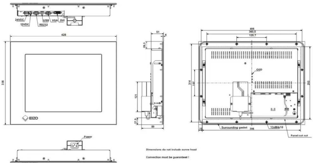
Dimensions do not include screw head
Convection must be guaranteed!
Fig. 1: Dimensions of the DV1508-002 (with AC power supply)
Operator Manual


Dimensions do not include screw head Convection must be guaranteed!
Fig. 2: Dimensions of the DV1508-004 (without AC power supply)
2.3 Connection and pin configuration
Before connecting the DV1508 to the power supply, the signal should be plugged in properly and the screws have been tightened.
The monitor can be connected directly to the power supply (check polarity of voltage connections). If a signal is connected, the image will appear on the screen immediately.
2.3.1 DVI Interface
The DVI interface is a 29-pin DVI-connector.
| Pin Signal | |
| 1 TMDS-Data 2 - | |
| 2 TMDS-Data 2 + | |
| 3 TMDS-Data Shield 2 (GND) | |
| 4 | - |
| 5 | - |
| 6 | DDC-CLK |
| 7 | DDC-DATA |
| 8 | Analogue V-Sync. |
| 9 TMDS-Data 1 - | |
| 10 TMDS-Data 1 + | |
| 11 TMDS-Data Shield 1 (GND) | |
| 12 | - |
| 13 | - |
| 14 +5 | V Power (In) |
| 15 | GND |
| 16 Hot Plug Detect | |
| 17 TMDS-Data 0 - | |
| 18 TMDS-Data 0 + | |
| 19 TMDS-Data Shield 0 (GND) | |
| 20 | - |
| 21 | - |
| 22 TMDS-CLK Shield (GND) | |
| 23 | TMDS-CLK + |
| 24 | TMDS-CLK - |

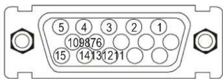
2.3.2 VGA Interface
The VGA interface is a standard 15-pin male HD-D-type connector.
| Pin Signal | |
| 1 Video input RED | |
| 2 Video input GREEN | |
| 3 Video input BLUE | |
| 4 | Not used |
| 5 | Not used |
| 6 | GND (RED) |
| 7 | GND (GREEN) |
| 8 | GND (BLUE) |
| 9 | Not used |
| 10 | GND |
| 11 | Not used |
| 12 | Not used |
| 13 | H-Sync. |
| 14 | V-Sync. |
| 15 | Not used |
2.3.3 Touch interface
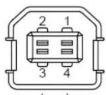
The Touch can be connected via the USB- or RS232 interface.
RS232
| Pin Signal | |
| 1 | DCD |
| 2 | RXD |
| 3 | TXD |
| 4 | DTR |
| 5 | GND |
| 6 | DSR |
| 7 | RTS |
| 8 | CTS |
| 9 | RI |

Operator Manual
USB
| Pin Signal | |
| 1 | +5V |
| 2 | Data - |
| 3 | Data + |
| 4 | GND |
2.3.4 Power Supply
The DV1508 has optional 12 V DC , 24 V DC and AC/DC power supply.
2.3.4.1 Power Supply 12 V DC
The connector is a 3.2 mm DC-female
| Pin | Name | Description |
| O | GND | Power supply GND |
| ● | +12V | Power supply +12 V DC |
2.3.4.2 Power Supply 24 V DC
The interface is equipped with Phoenix connector.
| Pin | Signal |
| 1 | GND |
| 2 | NC |
| 3 | +24 |

2.3.4.3 Installation of the AC/DC power supply (for DV1508-002)
The cable from the AC/DC power supply unit (12 V_DC ) is plugged directly into the 12 V_DC socket. It should be secured by using a pull-relief.
The bracket on the back will be used to fix the AC/DC-power supply.
2.4 Electrical Installation
Before connecting the DV1508 to the power supply, take care that the signal is plugged in properly and that the screws have been tightened.
The monitor can be connected directly to the power supply (check voltage level). If a valid signal is connected, the image will appear on the screen immediately.
There are some possible reasons if the unit does not show a picture when it is switched on:
- no valid input signal applied
- missing synchronization signals
• horizontal- and vertical synchronisation signals are permuted - wrong OSD adjustments
2.5 Installation Touch Screen
Software driver is needed for operation of the Touch Screen. The drivers and user manual can be found on the included CD-Rom.
3 Operation and alignment
This chapter contains a description of the operating and alignment functions.
3.1 Location of the operation and alignment
All operating controls can be accessed from the rear of the unit. The four keys are used for navigating and changing values in the OSD menu.

Fig. 3: Location of operation and alignment controls (DV1508-002)

Fig. 4: Location of operation and alignment controls (DV1508-004)
The functions of the keys are descript in chapter 3.2.1 and 3.2.2.
3.2 OSD-Menu / Quick-OSD-Menu
The “On Screen Display”-Menu (OSD-Menu) is graphic user interface for adjusting all monitor alignment. For control the four keys will be used (see Fig. 3).
In addition to the OSD menu (chap. 3.2.2) important functions can be adjusted directly via Quick-OSD-menu (chap 3.2.1).
Operator Manual
3.2.1 Quick OSD Menu
Function(s) of the control keys:
| Key Function | |
| <+> | Start Quick-OSD-MenuIncrease the parameter valueSelection of the input signalAutomatically alignment of the pictures |
| <-> | Decrease the parameter value |
| MENU | No function in the Quick-OSD |
| SET | Start Quick-OSD-MenuAdjust the contrast / brightnessZoom and picture in picture characteristics |
Invoke via key
| Function | Adjustment / value | Description |
 | Range: 0 to 100 via key <+>/<-> | Brightness adjustment |
 | Range: 0 to 100 via key <+>/<-> | Contrast adjustment |
Invoke via key <+>
| Function Adjustment / value Description | ||
| Source select digital DVI, analog RGB | Press <SET> to choose; Press <+> to select | Selection of input-source |
 | Press key <+> to start adjustment | Performs an automatic image adjustment if an analog VGA signal is connected. Adjustment of frequency, phase and image position |
3.2.2 OSD Menu
Function(s) of the control keys:
| Key Function | |
| <+> | Increase the parameter valueGo to the right |
| <-> | Decrease the parameter valueGo to the left |
| MENÜ | Start OSDSelect the main menu/submenu |
| SET | Scroll down or select menu item in main menu / submenu |
Invoke via key

The OSD menu options depend on the selected signal source VGA or digital DVI.
3.2.2.1 Structure of the On Screen Display Menu (analog/VGA)
| Main menu | Function | Adjust function / value / range | Description |
| pictureH Position setting | Brightness | setting range:0 to 100 through key (+/-) | adjust brightness |
| Contrast | setting range:0 to 100 through key (+/-) | adjust contrast | |
| setting range: | 0 to 100 through key (+/-) | move picture in horizontal direction | |
| V-Position | setting range:0 to 100 through key (+/-) | move picture in vertical direction | |
| Phase | setting range:0 to 31 through key (+/-) | adjust phase o input signal | |
| Frequency | setting range:950 to 1050 (dependent to picture)through key (+/-) | adjust frequency of input signal | |
| scaling | fill all, fill aspect ratio | fixed defined scaling of the picture | |
| AdvancedGamma | Sharpness | 1, 2, 3, 4, 5 | adjust sharpness of the picture by using no. 1 to 5 (Filter). 1=sharp and 5=soft |
| Linear or CRT | correction of gamma curvevalue of colors will be forwarded to the display | ||
| Color temperature | 5000 - 7300 - 9300 - user | color temperature / adjust colorthree defined and one adjustable color temperatures are for selection Pennate "user" for VGA shows up a adjustment beam0 to 100 % (50% correspond to factor 1) | |
| Option 1OSD H-PositionOSD V-Position | OSD | select between nine defined OSD positions | define position OSD |
| setting range: | 0 to 100 through (+/-) | move OSD menu in horizontal position | |
| setting range: | 0 to 100 through key (+/-) | move OSD menu in vertical position | |
| OSD time out | 5 ... 60 Seconds | adjust time after the OSD menu is automatically fade out,the adjustment ensures between 5 to 60 s in Steps of 5 s. | |
| OSD background | Opaque - Transparent | select background color of the OSD menuyou have the choice between transparent and colored background. | |
| Backlight | setting range:0 to 100 through key (+/-) | adjust brightness on backlightherewith you can match the brightness of the picture with the brightness of the room | |
Operator Manual
| Main menu | Function | Adjust function / value / range | Description |
| Option 2Source scan on | DPMS | on - off | Display Power management System (DPMS) on or off.If DMPS activated, the monitor is turn off (backlight) when a sync signal is left. The screen is dark |
| on - off - default Standard: ON | Note: To scan new video source is not relevant because the monitor has one VGA input source only. | ||
| Blank color red | - green - blue - black Choose the background color of the screen when no input signal is present. | ||
| Source icon | on - off Input source icon on or off | The icon is shown when input signal are changed. The icon shows the following information's:- signal source (e.g. VGA analog)- mode number (internal mode number of the timing list)- Image resolution of the input signal- H- and V- frequency Analog RGB1Modus: %d, %d x %d%u,%03u kHz / %u Hz Analog RGB1Modus: %d, %d x %d%u,%03u kHz / %u Hz | |
| Option 3 RGB Noise suppression | ON - OFF | Standard setting OFF. At ON: Activation of function for noise suppression in synchronization signals. Inhibits new auto-alignment during display of a video signal when short-term noise is present on synchronous signals. | |
| Unlock RGB Timing 1 | ON <+ Key> | Standard setting OFF. At ON : The video timing currently shown will be stored, and processed with higher tolerance in H- and V- frequency. I.e. the settings of this timing will always be used, even if variations in H- and V-frequency will occur by noise.Prevents erroneous recognition of timing when recognizing a noisy video signal, e.g. showing up as wrong centring or resolution of picture. | |
| Unlock RGB Timing 2 | OFF <+ Key> | Standard setting OFF.(Video timing 1 released again). | |
| ON <+ Key> | Standard setting OFF. At ON : The video timing currently shown will be stored, and processed with higher tolerance in H- and V- frequency. I.e. the settings of this timing will always be used, even if variations in H- and V-frequency will occur by noise.Prevents erroneous recognition of timing when recognizing a noisy video signal, e.g. showing up as wrong centring or resolution of picture. | ||
| OFF <+ Key> | Standard setting OFF.(Video timing 2 released again). | ||
| Utilities Language Factory reset | <--> press Reset of values | like brightness, contrast,...to default values. | |
| Installation Mode | <-->Press Enter a new timing which is not in the internal timing table. This function should used, when the shown image resolution is not the resolution are expect.When press <--> the sub menu expect 9 timing parameter. | ||
| When H- and V-Frequency | <++, - | Show the H- and V-Frequency of the present input signal | |
| H/V-total, H/V-start | - | Show the use timing parameter of the present input signal | |
| Options | disable, Mode1, Mode2, Mode3 | disable: used the internal timing table onlyMode1: use the timing parameter and perform a complete auto adjustment (usually used)Mode2: use the timing parameter and perform an auto adjustment without an automatic image position adjustment. Mode3: use the timing parameter and perform an auto adjustment without an automatic frequency adjustment | |
| H-visible | 100 to 2000 through key (+/-) | Horizontal image resolution ( important parameter) | |
| V-visible | 100 to 2000 through key (+/-) | Vertical image resolution ( important parameter) | |
| H-total | 100 to 2500 through key (+/-) | Whole pixel per line ( important parameter) | |
| H-start | 0 to 750 through (+/-) | Number of Pixels from H-sync start to image start | |
| V-start | 0 to 500 through (+/-) | Number of lines from V-sync start to image start | |
| Install Test pattern | <--> press Activate the feed timing parameter | ||
| <--> press Show a test image | |||
| Info | Firmware, Resolution, Timing | - | Show the firmware version and timing data of the present input signal |
3.2.2.2 Structure of the On Screen Display Menu (digital/DVI)
| Main menu | Function | Adjust function / value / range | Description |
| Picture | Brightness | setting range:0 to 100 through key (+/-) | adjust brightness |
| Contrast | setting range:0 to 100 through key (+/-) | adjust contrastchange contrast between dark and light colors | |
| scaling | fill all, fill aspect ratio | fixed defined scaling of the picture | |
| Advanced | See chapter “Structure of the OSD-Menu-Function (VGA)” page 43 | ||
| Option 1 | See chapter “Structure of the OSD-Menu-Function (VGA)” page 43 | ||
| Option 2 | See chapter “Structure of the OSD-Menu-Function (VGA)” page 44 | ||
| Option 3 | See chapter “Structure of the OSD-Menu-Function (VGA)” page 44 | ||
| Utilities | See chapter “Structure of the OSD-Menu-Function (VGA)” page 45 | ||
| Info | See chapter “Structure of the OSD-Menu-Function (VGA)” page 45 | ||
4 Technical data
4.1 Display module
| Type | active Color TFT-LCD |
| Diagonal | 38.0 cm (15,0") |
| Display area (B x H) | 304.1 x 228.1 mm ^2 |
| Resolution | 1024 x 768 Pixel |
| Pixel pitch | 0.297 x 0.297 mm ^2 |
| Color | 16.2 Mio. |
| Backlight | 2 x CCFT (Cold Cathode Fluorescent Tube) |
| Brightness (typical) | approx. 250 cd/m ^2 |
| Contrast | 550:1 |
4.2 Power supply
| Input voltageLimited power source max. 8A | 11.4 – 13.2 V_DC 18 – 36 V_DC 100 – 240 V_AC (for DV1508-002) |
| Current consumption(Normal operation) | 1.2 A0.7 Amax.0.25 A (for DV1508-002) |
| Power consumption (Stand By) | approx. 4 W |
4.3 Operating conditions
| Operating temperature | 0 to +40 °C |
| Storage temperature | -25 to +60 °C |
| Humidity | max. 95% (non condensing) |
4.4 Protection
| Protection class | IP65 |
| Front screen | non mirror glass |
4.5 Housing
| Weight DV1508-002DV1508-004 approx. 4.0 kg | approx. 4.4 kg |
| Material housing | Aluminium |
4.6 Input signal
4.6.1 Analog VGA
| Level (Video) | 0.7Vss VGA analog at 75 Ω |
| Bandwidth | 500 MHz (-3 dB) |
| Impedance | 75 Ω |
| Synchronization | Sep. Sync. (TTL)Sync on greenComposite Sync |
| H- Frequency | 30 to 100 KHz |
| V- Frequency | 50 to 75 Hz |
| Pixel Frequency | 25 – 140 MHz |
4.6.2 Digital DVI
| Type | Standard signal DVI 1.0 |
| Pixel Frequency | 25 – 140 MHz |
4.7 EU Declaration of conformity on EMC
Product
LCD-Monitor DV1508
Test foundations
EU guidelines No. 2004/108/EC
No. 2006/95/EC
Harmonized standards
EN 55022 Class A Interference emission
(industrial)
EN 61000-6-2 Interference
resistance (industrial)
EN 60950
Safety
Operator Manual

EIZO®
Notes:

- 15,0" XGA LCD Monitor
- DuraVision™ DV1508-002
- DuraVision™ DV1508-004
- Inhalt
- Installation Touch Screen
- Content
- Figures
- Overview
- Layout of the Handbook
- Warning and safety notes
- Transport
- Setting Up
- EMC
- Repairs
- Cleaning
- Instructions for handling electrostatic susceptible assemblies
- General installation
- Removing the packaging and checking individual Parts
- Installing the Monitor
- Thermal Considerations
- EMC Considerations
- Safety Considerations
- Ergonomics
- Mechanical Installation
- Operator Manual
- Connection and pin configuration
- DVI Interface
- VGA Interface
- Touch interface
- Power Supply
- Power Supply 12 V DC
- Power Supply 24 V DC
- Installation of the AC/DC power supply (for DV1508-002)
- Electrical Installation
- Operation and alignment
- Location of the operation and alignment
- OSD-Menu / Quick-OSD-Menu
- Quick OSD Menu
- OSD Menu
- Structure of the On Screen Display Menu (digital/DVI)
- Technical data
- Display module
- Power supply
- Operating conditions
- Protection
- Housing
- Input signal
- Analog VGA
- Digital DVI
- EU Declaration of conformity on EMC
Brand : EIZO
Model : DuraVision DV1508-002
Category : Screen