
DuraVision FDX1201T - Screen EIZO - Free user manual and instructions
Find the device manual for free DuraVision FDX1201T EIZO in PDF.


| Product Type | Touch Panel Color LCD Monitor |
| Screen Size (Diagonal) | 12.1 inches (310 mm) |
| Panel Type | TFT Color LCD with LED backlight |
| Resolution | 1024 x 768 (XGA) |
| Maximum Brightness | 780 cd/m² |
| Display Colors | Approx. 16.7 million |
| Viewing Angle (Horizontal / Vertical) | 160° / 140° (CR ≥ 10) |
| PC Input Connector | D-Sub mini 15-pin (analog RGB) |
| Video Input Connector | S-Video (DIN 4-pin) and Composite (RCA) |
| Touch Panel Technology | Analog resistive (RS-232C) |
| Supported Operating Systems | Windows 7 (32/64), Vista (32), XP (32) |
| Power Supply | AC 100-240V, 50/60 Hz (adapter); DC 12V, 1.4A |
| Power Consumption (On) | 20 W (AC) / 17 W (DC) |
| Power Consumption (Off) | 1.6 W (AC) / 0.8 W (DC) |
| Dimensions (with stand) | 293 × 271 × 175 mm |
| Dimensions (without stand) | 293 × 244 × 46 mm |
| Weight (with stand) | Approx. 4.4 kg |
| Weight (without stand) | Approx. 2.8 kg |
| Tilt / Swivel Range | Tilt: 30° up, 0° down; Swivel: 35° left/right |
| VESA Mounting | 100 × 100 mm (M4 × 12 mm screws) |
| Operating Temperature / Humidity | 0°C to 50°C / 20% to 90% RH (non-condensing) |
| Special Functions | Crosshair display, Video aspect, Reverse mode, Power Save |
| Cleaning Instructions | Use soft cloth with water or optional ScreenCleaner; avoid alcohol, thinner, benzene |
| Warranty | 2 years from date of purchase |
Frequently Asked Questions - DuraVision FDX1201T EIZO
User questions about DuraVision FDX1201T EIZO
0 question about this device. Answer the ones you know or ask your own.
Ask a new question about this device
Download the instructions for your Screen in PDF format for free! Find your manual DuraVision FDX1201T - EIZO and take your electronic device back in hand. On this page are published all the documents necessary for the use of your device. DuraVision FDX1201T by EIZO.
USER MANUAL DuraVision FDX1201T EIZO
Please read this User's Manual carefully to familiarize yourself with safe and effective usage. Please retain this manual for future reference.
重要事项
FCC Declaration of Conformity
We, the Responsible Party EIZO NANAO TECHNOLOGIES INC.
5710 Warland Drive, Cypress, CA 90630
Phone: (562) 431-5011
declare that the product Trade name: EIZO
Model: DuraVision FDX1001T/FDV1001T/FDX1201T
is in conformity with Part 15 of the FCC Rules. Operation of this product is subject to the following two conditions: (1) this device may not cause harmful interference, and (2) this device must accept any interference received, including interference that may cause undesired operation.
This equipment has been tested and found to comply with the limits for a Class B digital device, pursuant to Part 15 of the FCC Rules. These limits are designed to provide reasonable protection against harmful interference in a residential installation. This equipment generates, uses, and can radiate radio frequency energy and, if not installed and used in accordance with the instructions, may cause harmful interference to radio communications. However, there is no guarantee that interference will not occur in a particular installation. If this equipment does cause harmful interference to radio or television reception, which can be determined by turning the equipment off and on, the user is encouraged to try to correct the interference by one or more of the following measures.
* Reorient or relocate the receiving antenna.
* Increase the separation between the equipment and receiver.
* Connect the equipment into an outlet on a circuit different from that to which the receiver is connected.
* Consult the dealer or an experienced radio/TV technician for help.
Changes or modifications not expressly approved by the party responsible for compliance could void the user's authority to operate the equipment.
Canadian Notice
This Class B digital apparatus complies with Canadian ICES-003.
Touch Panel Color LCD Monitor
SAFETY SYMBOLS
This manual and this product use the safety symbols below. They denote critical information. Please read them carefully.
| WARNINGFailure to abide by the information in a WARNING may result in serious injury and can be life threatening. | ||
| CAUTIONFailure to abide by the information in a CAUTION may result in moderate injury and/or property or product damage. | ||
 | Indicates an attention to be required. For example, the symbol illustrates the hazard type such as “the risk of electric shock”. | |
 | Indicates a prohibited action. For example, the symbol illustrates a particular prohibited action such as “Do not disassemble”. | |
 | Indicates a mandatory action that must be followed. For example, the symbol illustrates the notification of general prohibition such as “Grounding the unit”. | |
Using the special functions, such as screen size change (ex. changing the horizontal and vertical ratio of images input) for commercial purposes or for the purpose of showing in public may violate copyright laws.
This product has been adjusted specifically for use in the region to which it was originally shipped. If operated outside this region, the product may not perform as stated in the specifications.
No part of this manual may be reproduced, stored in a retrieval system, or transmitted, in any form or by any means, electronic, mechanical, or otherwise, without the prior written permission of EIZO NANAO CORPORATION. EIZO NANAO CORPORATION is under no obligation to hold any submitted material or information confidential unless prior arrangements are made pursuant to EIZO NANAO CORPORATION's receipt of said information. Although every effort has been made to ensure that this manual provides up-to-date information, please note that EIZO monitor specifications are subject to change without notice.
Apple, ColorSync, eMac, iBook, iMac, iPad, Mac, MacBook, Macintosh, Mac OS, PowerBook, and QuickTime are registered trademarks of Apple Inc.
Windows, Windows Media, Windows Vista, SQL Server, and Xbox 360 are registered trademarks of Microsoft Corporation in the United States and other countries.
VESA is a registered trademark of Video Electronics Standards Association.
NEC is a registered trademark of NEC Corporation.
PC-9801 and PC-9821 are trademarks of NEC Corporation.
EIZO, the EIZO Logo, ColorEdge, DuraVision, FlexScan, FORIS, RadiCS, RadiForce, RadiNET, Raptor, and ScreenManager are registered trademarks of EIZO NANAO CORPORATION in Japan and other countries.
All other company and product names are trademarks or registered trademarks of their respective owners.

PRECAUTIONS
IMPORTANT
- To ensure personal safety and proper maintenance, please read this section and the caution statements on the unit (refer to the figure below).
【Location of Caution Statement】

If the unit begins to emit smoke, smells like something is burning, or makes strange noises, disconnect all power connections immediately and contact your dealer for advice.
Attempting to use a malfunctioning unit may result in fire, electric shock, or equipment damage.
Do not open the cabinet or modify the unit.
Opening the cabinet or modifying the unit may result in fire, electric shock, or burn.

Refer all servicing to qualified service personnel.
Do not attempt to service this product yourself as opening or removing covers may result in fire, electric shock, or equipment damage.
Keep small objects or liquids away from the unit.
Small objects accidentally falling through the ventilation slots into the cabinet or spillage into the cabinet may result in fire, electric shock, or equipment damage. If an object or liquid falls/spills into the cabinet, unplug the unit immediately. Have the unit checked by a qualified service engineer before using it again.

Place the unit at the strong and stable place.
A unit placed on an inadequate surface may fall and result in injury or equipment damage. If the unit falls, disconnect the power immediately and ask your dealer for advice. Do not continue using a damaged unit. Using a damaged unit may result in fire or electric shock.
Use the unit in an appropriate location.
Not doing so may result in fire, electric shock, or equipment damage.
- Do not place outdoors.
- Do not place in a transportation system (ship, aircraft, train, automobile, etc.) where it may be affected by strong vibration or shock.
- Do not place in a dusty or humid environment.
- Do not place in a location where water is splashed on the screen (bathroom, kitchen, etc.).
- Do not place in a location where the steam comes directly on the screen.
- Do not place near heat generating devices or a humidifier.
- Do not place in a location where the product is subject to direct sunlight.
- Do not place in an inflammable gas environment.

To avoid danger of suffocation, keep the plastic packing bags away from babies and children.
Use the enclose AC adapter.
The enclosed AC adapter is for use with this product only. Do not use the AC adapter with other equipment. Connecting to power sources that do not match the power ratings of the AC adapter may result in fire or electric shock.
Make sure the power cord meets the following requirements.
This product does not include a power cord. Please provide separately a power cord which meets the requirements. (For more information, please contact your dealer.)
- The power cord is compatible with the standards of the country and region in which this product is to be used.
• The power cord has a rated value of at least 2.5A.
Power supply: 100-240Vac 50/60Hz
To disconnect the power cord, grasp the plug firmly and pull.
Tugging on the cord may damage and result in fire or electric shock.

Use the correct voltage.
- The unit is designed for use with a specific voltage only. Connection to another voltage than specified in this User's Manual may cause fire, electric shock, or equipment damage.
Power supply: 100-240Vac 50/60Hz - Do not overload your power circuit, as this may result in fire or electric shock.
Handle the power cord and AC adapter with care.
Do not place heavy objects on, pull or tie the power cord or the AC adapter. Use of a damaged cord or AC adapter may result in fire or electric shock.

Never touch the plug, AC adapter or power cord during a thunderstorm.
Touching them may result in electric shock.

When attaching an arm stand, please refer to the user's manual of the arm stand and install the unit securely.
Not doing so may cause the unit to become unattached, which may result in injury or equipment damage. When the unit is dropped, please ask your dealer for advice. Do not continue using a damaged unit.
Using a damaged unit may result in fire or electric shock. When reattaching the tilt stand, please use the same screws and tighten them securely.
Do not touch a damaged LCD panel directly with bare hands.
The liquid crystal that may leak from the panel is poisonous if it enters the eyes or mouth. If any part of the skin or body comes in direct contact with the panel, please wash thoroughly. If some physical symptoms result, please consult your doctor.


CAUTION
Handle with care when carrying the unit.
Disconnect the power cord and cables when moving the unit. Moving the unit with the cord attached is dangerous. It may result in injury.
When handling the unit, grip the bottom of the unit firmly with both hands ensuring the panel faces outward before lifting.
Dropping the unit may result in injury or equipment damage.

Do not install the unit in a closed space.
If the interior becomes hot, it may result in fire, electric shock or damage.

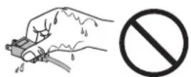
Do not touch the power plug or AC adapter with wet hands.
Doing so may result in electrical shock.
Use an easily accessible power outlet.
This will ensure that you can disconnect the power quickly in case of a problem.
Mind that the AC adapter becomes hot during use.
- Do not cover or place anything on top of the AC adapter. Do not place the AC adapter on top of things that trap heat such as carpets, blankets, etc. Keep the AC adapter away from direct sunlight and heat sources such as heaters.
Not doing so may result in fire.
- Do not touch with bare hands. Doing so may result in burns.
Do not suspend the AC adapter in midair.
Using it while suspended in midair may result in fire or electric shock.

Periodically clean the area around the plug.
Dust, water, or oil on the plug may result in fire.
Unplug the unit before cleaning it.
Cleaning the unit while it is plugged into a power outlet may result in electric shock.
If you plan to leave the unit unused for an extended period, disconnect the power cord from the wall socket after turning off the power for safety and power conservation.
Notice for this monitor
Aside from displaying microscope images, this product is also suited to the dedicated usages such as operation of terminal equipment.
This product has been adjusted specifically for use in the region to which it was originally shipped. If the product is used outside the region, it may not operate as specified in the specifications.
This product may not be covered by warranty for uses other than those described in this manual.
The specifications noted in this manual are only applicable when the following are used:
• Signal cables specified by us
Only use optional products manufactured or specified by us with this product.
As it takes about 30 minutes for the performance of electrical parts to stabilize, adjust the monitor 30 minutes or more after the monitor power has been turned on.
Monitors should be set to a lower brightness to reduce changes in luminosity caused by long-term use and maintain a stable display.
When the screen image is changed after displaying the same image for extended periods of time, an afterimage may appear. Use the screen saver or power save function to avoid displaying the same image for extended periods of time.
Periodic cleaning is recommended to keep the monitor looking new and to prolong its operation lifetime. (Refer to "Cleaning" on the next page.)
The LCD panel is manufactured using high-precision technology. Although, missing pixels or lit pixels may appear on the LCD panel, this is not a malfunction. Percentage of effective dots: 99.99% or higher.
The backlight of the LCD panel has a fixed lifetime. When the screen becomes dark or begins to flicker, please contact your local EIZO representative.
Do not scratch or press on the panel with any sharp objects, as this may result in damage to the panel. Do not attempt to brush with tissues as this may scratch the panel.
When the monitor is cold and brought into a room or the room temperature goes up quickly, dew condensation may occur on the interior and exterior surfaces of the monitor. In that case, do not turn the monitor on. Instead wait until the dew condensation disappears, otherwise it may cause some damage to the monitor.
(Cautions for the Use of the Touch Panel)
- During touch operation
Be careful of the following points. Otherwise, damage may occur to the monitor.
- Do not strongly press, scratch, or poke the panel.
- Do not touch the panel with hard objects such as ballpoint pens or metals.
Cleaning
ATTENTION
- Chemicals such as alcohol and antiseptic solution may cause gloss variation, tarnishing, and fading of the cabinet or panel, and also quality deterioration of the image.
- Never use any thinner, benzene, wax, and abrasive cleaner, which may damage the cabinet or panel.
- Do not allow liquid to enter the clearance between the panel and the panel frame.
NOTE
- The optional ScreenCleaner is recommended for cleaning the cabinet and panel surface.
If necessary, the stains on the cabinet and panel surface can be removed by moistening part of a soft cloth with water.
To use the monitor comfortably
- An excessively dark or bright screen may affect your eyes. Adjust the brightness of the monitor according to the environmental conditions.
- Staring at the monitor for a long time tires your eyes. Take a 10-minute rest every hour.
CONTENTS
Cover 1
PRECAUTIONS 3
Notice for this monitor 6
CONTENTS 8
Chapter 1 Introduction ...... 9
1-1. Features 9
1-2. Package Contents 9
1-3. Controls and Functions .... 10
Chapter 2 Connecting Cables.... 11
2-1. Connection Procedures .....11
- When used as a PC monitor ....11
- When using video equipment 12
2-2. Adjusting the Screen Angle .... 13
2-3. Installing the Touch Panel Driver .... 14
2-4.Calibrating the Monitor 14
Chapter 3 Settings and Adjustments .... 15
3-1. Basic Operation and Functions ..... 15
3-2. Color Adjustment 17
3-3. Configure other settings 18
Chapter 4 Troubleshooting .... 19
Chapter 5 Reference ...... 21
5-1. Attaching an Arm 21
5-2. Specifications 22
5-3. Glossary 28
5-4. Preset Timing 29
LIMITED WARRANTY 30
Chapter 1 Introduction
Thank you very much for choosing an EIZO color LCD monitor.
1-1. Features
- FDX1001T/FDV1001T: 10.4-inch screen, FDX1201T: 12.1-inch screen
- Resolution
- FDX1001T/FDX1201T: XGA (1024 × 768) display compliant
- FDV1001T: VGA (640 × 480) display compliant
• Maximum brightness
FDX1001T: 460 cd/m², FDV1001T: 350 cd/m², FDX1201T: 780 cd/m²
• LED backlight LCD panel
The LED backlight provides better power efficiency and reduced power consumption compared to existing fluorescent backlight LCD panels.
No mercury, a hazardous substance, is used.
- Analog signal support
- FDX1001T/FDX1201T: Horizontal scanning frequency 24 kHz - 50 kHz Vertical scanning frequency 55 Hz - 75 Hz
- FDV1001T: Horizontal scanning frequency 24 kHz - 32 kHz Vertical scanning frequency 56 Hz - 70.5 Hz
Video signal: S-Video/ Video input connector × 1
- Applicable Format NTSC, PAL, SECAM
- Resistive technology touch panel function Enables touch operation of the PC screen.
• Crosshair display function
Displays lines (Fine, Circle or Broken Line) as a reference for the position of the image displayed on the monitor. 3-3. Configure other settings (page 18)
• Video aspect function
Alters the display range of the input image (overscan). 3-3. Configure other settings (page 18)
1-2. Package Contents
Check that all the following items are included in the packaging box. If any items are missing or damaged, contact your local dealer.
NOTE
- Please retain the packing materials for future transport of the monitor.
- LCD Monitor
- AC Adapter
- Cable Tie
- User's Manual (Limited Warranty included)
• EIZO LCD Utility Disk (CD-ROM) ^*1
- RS-232C Cable
*1 The disk includes the touch panel driver.
For how to install the touch panel driver, see the Touch Panel Driver User's Manual (on the CD-ROM).
ATTENTION
- This product does not include a power cord. Please provide separately a power cord which meets the usage requirements.
1-3. Controls and Functions
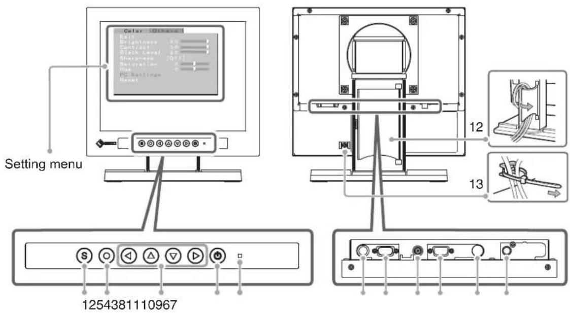
| 1 | button Switches the input signal. | |
| 2 | ◎ button | Displays the Setting menu, fixes the setting or adjustment items on each menu,and saves the setting or adjustment results. |
| 3 | ◀ △ ▼ ▶ button | • Used to select the setting or adjustment items, or to increase or decrease theadjustment values on each menu.• When the settings menu is not displayed, pressing △ or ▽ switchesbetween displaying and not displaying the crosshair. |
| 4 | ◎ button Turns the power | on or off. |
| 5 | Power indicator | Indicates monitor's operation status.Blue : OperatingOrange : Power off |
| 6 | Maintenance port | For monitor control |
| 7 | Serial port for the touchpanel | Connects the PC to the monitor with an RS-232C cable. |
| 8 | Power jack (DC-IN) | Connects to the AC adapter. |
| 9 | Input signal connector | D-Sub mini 15-pin connector × 1 |
| 10 | Input signal connector | S-Video input connector × 1 |
| 11 | Input signal connector | Video input connector × 1 |
| 12 | Cable holder | Covers the monitor cables. |
| 13 | Cable tie | Clinches the cables. |
Chapter 2 Connecting Cables
2-1. Connection Procedures
1 Connects to external equipment compatible with the monitor.
- When used as a PC monitor ...... page 11
- When using video equipment . . . . . . . . . . . . . . . . . . . . . . . . . . . . . . . . . . . . . page 12
- When used as a PC monitor
ATTENTION
- When replacing the current monitor with an FDX1001T / FDV1001T /FDX1201T monitor, be sure to change the PC settings for resolution and vertical frequency to those which are available for the FDX1001T / FDV1001T/ FDX1201T monitor referring to the resolution table (see below) before connecting the PC.
Compatible Resolutions/Frequencies
The monitor supports the following resolutions.
• FDX1001T/FDX1201T
| Resolution Display Mode Frequency Dot Clock | |||
| 640 × 400 NEC PC-9801 56 Hz | ~65 MHz | ||
| 640 × 400 NEC PC-9821 AP2 70 Hz | |||
| 640 × 480 Apple Macintosh 67 Hz | |||
| 640 × 480 | VGA, VESA | ~75 Hz | |
| 720 × 400 | VGA TEXT | 70 Hz | |
| 800 × 600 | VESA | ~75 Hz | |
| 832 × 624 | Apple Macintosh 75 Hz | ||
| 1024 × 768*1 | VESA | 60 Hz | |
^*1 Recommended resolution (Set this resolution.)
- FDV1001T
| Resolution Display Mode Frequency Dot Clock | |||
| 640 × 480 Apple Macintosh 67 Hz | ~31 MHz | ||
| 640 × 480 | VGA | 60 Hz | |
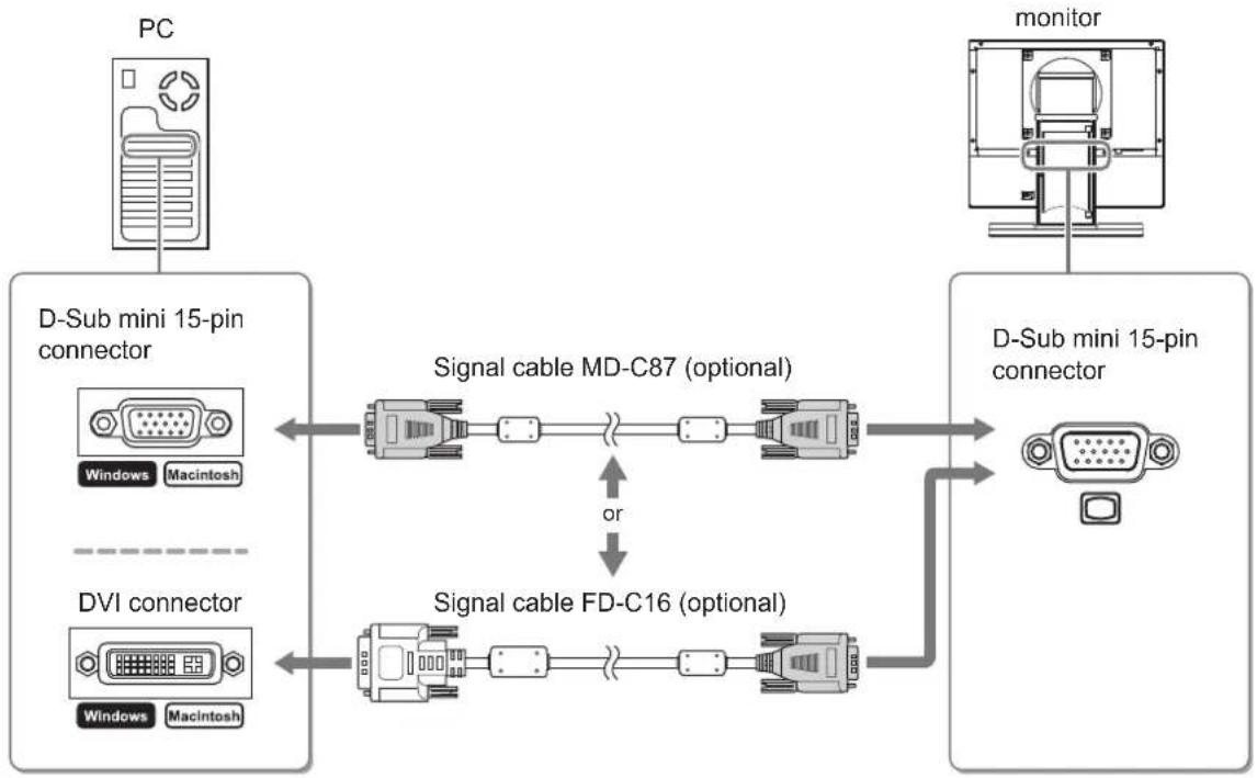
(1) Connect the monitor to the PC with a signal cable that matches the connectors.
After connecting the cable connectors, tighten the screws of the connectors to secure the coupling.
flowchart
graph LR
    PC["PC"] --> D2["D-Sub mini 15-pin connector"]
    D2 -->|Signal cable MD-C87 (optional)| Monitor["monitor"]
    Monitor --> D3["D-Sub mini 15-pin connector"]
    D3 -->|Signal cable FD-C16 (optional)| D4["DVI connector"]
    D4 -->|Signal cable MD-C87 (optional) or FD-C16| D2
    style PC fill:#f9f,stroke:#333
    style Monitor fill:#ccf,stroke:#333
    style D2 fill:#dfd,stroke:#333
    style D3 fill:#dfd,stroke:#333
    style D4 fill:#dfd,stroke:#333
- When using video equipment
(1) Connect the monitor to the video equipment with a signal cable that matches the connectors.

flowchart
graph LR
    A["Video equipment"] --> B["S-Video"]
    B --> C["S-Video cable (Commercially available product)"]
    C --> D["Monitor"]
    D --> E["S-Video"]
    E --> F["Video"]
    B --> G["Video"]
    G --> H["Video cable (Commercially available product)"]
    H --> I["Video"]
    style A fill:#f9f,stroke:#333
    style D fill:#ccf,stroke:#333
2 Plug the power cord of the monitor into a power outlet.
(1) Connect the power cord to the AC adapter.
(2) Connect the AC adapter to the Power jack of the monitor, and after that, connect the power plug to a power outlet.
ATTENTION
- This product does not include a power cord. Please provide separately a power cord which meets the usage requirements.
- For the maximum power saving, it is recommended that the Power button be turned off. Unplugging the power cord completely shuts off power supply to the monitor.
2-2. Adjusting the Screen Angle
Hold left and right edge of the monitor with both hands, and adjust the tilt and swivel to the best condition for working.

natural_image
Illustration of two hands holding a blank computer monitor with directional arrows indicating rotation (no text or symbols)
natural_image
Technical line drawing of a mechanical assembly with no visible text or symbols2-3. Installing the Touch Panel Driver
ATTENTION
- The user account to be used for installing the touch panel driver must have the “Administrators” privilege.
- When reinstalling the touch panel driver to update the driver, etc., restart the PC after uninstalling the driver and then install it.
1 Uninstall the other touch panel driver, if it is installed.
2 Install the touch panel driver according to the instructions included in the CD-ROM.
For how to install the touch panel driver, see the Touch Panel Driver User's Manual (on the CD-ROM).
3 Connect the monitor to the PC with the included RS-232C signal cable.

flowchart
graph LR
    A["Connectors on the PC"] --> B["COM port"]
    B <--> C["RS-232C Cable (supplied)"]
    C <--> D["Connectors on the monitor"]
    D --> E["Serial port for the touch panel"]
4 Restart the PC.
ATTENTION
- After the restart, set up the device using the following procedure. For details, refer to the Touch Panel Driver User's Manual (on the CD-ROM).
- Click "Start" - "All Program" - "DMC" - "DMC Touch Panel Configuration" to display the [Properties] window.
- Click "Add a serial device", and register a new serial device.
- Click "Device", and specify the COM port number used for [COM port].
- Click "Apply".
- Click "Close".
2-4. Calibrating the Monitor
Calibrate the monitor according to the instruction manual for the touch panel driver on the CD-ROM.
Chapter 3 Settings and Adjustments
3-1. Basic Operation and Functions
Basic operation of Setting menu
1 Displaying Setting Menu
Press
2 Setting/Adjusting
![When a tab is selected (highlighted in yellow), press 🔒 or ➕ to switch tabs. Color Others Exit 30 Brightness 30 Contrast 30 Black Level 30 Sharpness [Off] Saturation 0 Hue 0 PC Settings Reset Select a setting or adjustable item with ⚠ or ▼ , and press ⚠. Pressing ⚠ on [Reset] will reset all the currently displayed settings to the default configuration. ① Press ⚠. All your settings will be lost. Execute Cancel ② Select "Execute" in the confirmation dialog box, and press ⚠. Pressing ⚠ on an item with a setting value brings up a selection menu. Sharpness Off Low High Select a setting value with ⚠ or ▼ , and press ⚠. Pressing ⚠ on an item without a setting value brings up a more detailed Setting menu. Color Others PC Settings Return Clock Phase Position Range Adjustment Color Mode [1] Red 128 f Green 128 f Blue 128 f Reset When done configuring the various items, choose [Return], and press ⚠ to return to the previous menu.](/content/2026/06/1179011/images/09102f16fea0675ca7d0791b84b87f1bce314b5859d1394b5cfd7df326352b1d.jpg)
3 Exiting
Choose [Exit] with △, and press.
NOTE
- Keeping pressed for 2 seconds will also exit the Setting menu.
Functions
The settings adjustable in the Setting menu are as shown below. The availability of items depends on the input signal.
√ : Configurable — : Not configurable
| Tab Setting / adjustable item PC Video Reference | ||||
| Color Brightness | √√ | page 17 | ||
| Contrast | √√ | |||
| Black Level | √√ | |||
| Sharpness — | √ | |||
| Saturation — | √ | |||
| Hue — | √ | |||
| PC Settings Clock | √ | |||
| Phase | √ | |||
| Position | √ | |||
| Range Adjustment | √ | |||
| Color Mode | √ | |||
| Red/Green/Blue | √ | |||
| Reset | √ | |||
| Reset | √√ | |||
| Others Video Aspect — | √ | |||
| Power Save | √√ | |||
| Reverse | √√ | |||
| Crosshair | √√ | |||
| Color | √√ | |||
| Width | √√ | |||
| Beep | √√ | |||
| Language | √√ | |||
| Touch Panel | √√ | |||
| Information | √√ | |||
3-2. Color Adjustment
This will perform color adjustments.
Please switch between the input screens you want to adjust and adjust them one by one.
| Adjustable item / adjustable value Adjusting | |||
| Brightness 0 - 30 | Adjusts the brightness of the backlight. | ||
| Contrast 0 - 30 Adjusts the contrast. | |||
| Black Level 0 - 30 Adjusts the image brightness. | |||
| Sharpness Off/Low/High Adjusts the image outlines. | |||
| Saturation -30 - +30 Adjusts the saturation. | |||
| Hue -30 - +30 Adjusts the hue. | |||
| PC Settings*1 | Clock Adjust this when vertical bars appear. | ||
| Phase Adjust this when the screen appears to flicker or blur. | |||
| Position Adjust this when the display positioning is misaligned. | |||
| Range Adjustment Provides automatic adjustment when you want every color gradients displayed. | |||
| Color Mode*2 | 1/2/3 Select Color Mode (1/2/3) to adjust the colors of red, green and blue in several modes. | ||
| Red/Green/Blue | 0 - 128 | ||
| Reset Resets the state adjusted with [PC Settings] to the factory default. | |||
| Reset | Resets the state adjusted with the [Color] tab to the factory default (excluding [PC Settings]). | ||
^1 This setting becomes available when a PC is connected to the monitor. Please adjust with a PC when display and color adjustments are required.
^2 Perform [Range Adjustment] before adjusting Color Mode.
3-3. Configure other settings
This will configure other settings.
| Setting item / setting value Setting | |||
| Video Aspect Normal/100% Configures the display range of the input image (overscan). | |||
“Normal”: Displays the input image with the outmost parts slightly cut off.  * This is how display devices normally display images. * This is how display devices normally display images. | |||
| “100%”: Displays most of the input image.* Because a part of the image which normally gets cut off is displayed as well, noise may be visible around the outmost parts, depending on the input signal. | |||
| Power Save Disable/Enable Automatically turns off the power supply if no video signal has been received for 15 minutes during PC or video viewing. | |||
| Reverse Off/On D splays the image upside down (180 degree rotation). | |||
| Crosshair Off/Fine/Circle/Broken Line | Displays a crosshair as a reference for the position of the image.“Fine” “Circle” “Broken Line”  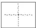 (When the settings menu is not displayed, pressingarswitches between displaying and not displaying the crosshair.) (When the settings menu is not displayed, pressingarswitches between displaying and not displaying the crosshair.) | ||
| Color When “Fine” is selected: Black/White/Red/GreenWhen “Circle” or “Broken Line” is selected: Black/White | Configures the color of the crosshair. | ||
| Width Narrow/Wide Configures the thickness of the crosshair’s lines. | |||
| Beep | Off/On Sets button press sounds and connection error sounds to on or off.· Short beep:- Whenospressed.- When an item is selected withos.- When a maximum or minimum value is set withosorpos· Long beep: When registration is performed withos.· 2 short beeps: When the Setting menu is displayed andosis pressed.· 4 short beeps:- When there is no input signal.- When a frequency out of the specified range is received. | ||
| Language | 日本語/English | Configures the displayed Setting menu and message language | |
| Touch Panel | PC+VIDEO/PC/VIDEO | Select an input that enables touch panel operation. | |
| Information | Reviews the input signals, usage time and model name. | ||
Chapter 4 Troubleshooting
If a problem still remains after applying the suggested remedies, contact your local dealer.
Common
| Problems Possible cause and remedy | |
| No picture• Power indicator does not light. | • Check whether the power cord is connected correctly.• If the problem persists, turn off the power, and then turn it on again a few minutes later. |
| • Power indicator lights orange. | • Press ⏻. |
| • Power indicator lights blue. • Check whether the power of the connected device is turned on.• Switch the input signal.• Set each adjusting value in [Brightness] and [Contrast] to higher level. (see page 17) | |
| The screen is too bright or too dark. • Adjust using [Brightness] or [Contrast]. (The LCD monitor backlight has a fixed life span. When the screen becomes dark or begins to flicker, contact your local dealer.) (see page 17) | |
| Green/red/blue/white dots or defective dots remain on the screen. | • This is due to LCD panel characteristics and is not a failure. |
| Interference patterns or pressure marks remain on the screen. | • Leave the monitor with a white or black screen. The symptom may disappear. |
| Afterimages appear. • Afterimages are particular to LCD monitors. Avoid displaying the same image for a long time.• When displaying the same image for extended periods of time, please set up the screen saver and/or make use of the power saving function. | |
When displaying on a PC screen
| Problems Possible cause and remedy | |
| The message below appears. • This message appears when the signal is not input correctly even when the monitor functions properly. | |
• This message appears when no signal is input.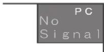 | • The message shown left may appear, because some PCs do not output the signal soon after power-on.• Check whether the PC is turned on.• Check whether the signal cable is connected properly. |
• The message shows that the input signal is out of the specified frequency range. | • Check whether the signal setting of your PC matches the resolution and the vertical frequency settings for the monitor. (see page 22, 23, 24) (Current input signal can be checked in [Information].)• Reboot the PC.• Select an appropriate display mode using the graphics board's utility. Refer to the manual of the graphics board for details. |
| Display position is incorrect. • Adjust image position using [Position]. (see page 17) | |
| Vertical bars appear on the screen or a part of the image is flickering. | • Adjust using [Clock]. (see page 17) |
| Whole screen is flickering or blurring. • Adjust using [Phase]. (see page 17) | |
| Characters are blurred. • This may occur when a non-complying high-resolution signal is input. Check the PC settings and change the resolution which complies with the monitor. | |
Touch panel problems
| Problems Possible cause and remedy | |
| Cursor position is not correct. / Cursor jumps. | Turn off and on the monitor. If the symptom is not improved, perform the calibration on the monitor.Touch with one finger only.Connect the monitor to the PC with the cable indicated in the User's Manual of the monitor. Using a conversion adapter, the touch panel may not operate properly. |
| Touch operation is not effective. Check | whether “Use EEPROM” in the [Device] menuis not checked in the [Properties] settings of the touch panel driver. If the check is already applied, perform the calibration.Other login user may have changed the setting. Set the touch panel driver again.Restart “DMC Touch Panel Configuration”, or reboot the PC. |
| Some deflection may appear on the surface of touch panel portion. | Due to the touch panel structural characteristics, the deflection may occur on the touch panel surface in high temperature/high humidity operating environment. This is not a trouble. |
| No touch-sound. The touch-sound may not be output from the external lineout of the PC depending on the hardware configuration.Under Windows 7, touch-sound is only output through the audio output terminal of the PC. To hear touch-sound, connect speakers. | |
Chapter 5 Reference
5-1. Attaching an Arm
The stand can be removed and replaced with an arm (or another stand) to be attached to the monitor. Use an arm or stand of EIZO option.
ATTENTION
- When attaching an arm or stand, follow the instructions of their user's manual.
- When using another manufacturer's arm or stand, confirm the following in advance and select one conforming to the VESA standard. Use the M4 × 12 mm screws in use by this monitor.
- Clearance between the screw holes : 100 mm × 100 mm
- Thickness of plate : 2.6 mm
- Strong enough to support weight of the monitor unit (except the stand) and attachments such as cables.
- Connect the cables after attaching an arm or a stand.
- Since the monitor and arm are so heavy, dropping them may result in injury or equipment damage.
- Do not turn the monitor lengthwise.
[Attachment Procedure]
1 Lay the LCD monitor on a soft cloth spread over on a stable surface with the panel surface facing down.
2 Remove the stand.
Prepare a screwdriver. Unscrew the four screws securing the unit and the stand with the screwdriver.
3 Attach the monitor to the arm or stand.
Secure the monitor to the arm or stand using the screws specified in the user's manual of the arm or stand.
![EIZO DuraVision FDX1201T - [Attachment Procedure] - 1](/content/2026/06/1179011/images/a756aac822c7b273327ec93968d0c29e7cf17eb44d648be916d92634d3577c0b.jpg)
natural_image
Technical line drawing of a mechanical assembly with alignment lines and components (no text or symbols)5-2. Specifications
FDX1001T
| LCD Panel Size | 10.4-inch (260 mm) TFT color LCD | |
| Surface treatment Anti-glare | ||
| Surface hardness 2H | ||
| Viewing angle Horizontal 160°, Vertical 130° (CR: 10 or more) | ||
| Dot Pitch 0.2055 mm | ||
| Display Area (H × V) 210.4 mm × 157.8 mm | ||
| Resolution 1024 dots × 768 lines | ||
| Max. Display Color Approx. 16.7 million colors | ||
| PC input Horizontal Scan Frequency 24-50 kHz | ||
| Video input | Applicable Format | NTSC, PAL, SECAM |
| Input Signal Connector S-Video DIN mini 4 pin/ Video Pin jack × 1 | ||
| Input Signal Level S-Video DIN mini 4 pin : Y 1.0Vp-p/75Ω, C 0.28Vp-p/75ΩVideo Pin jack : 1.0Vp-p/75Ω | ||
| Power Supply | AC adapter (AC) : 100-240VAC±10%, 50/60Hz, 0.3-0.2 A (Max.)Main unit (DC) : 12VDC±10%, 0.9 A | |
| Power Consumption | Screen Display On | AC adapter (AC) : 14 W or lessMain unit (DC) : 11 W or less |
| Power Off | AC adapter (AC) : 1.3 W or lessMain unit (DC) : 0.5 W or less | |
| Dimensions (Width) × (Height) × (Depth) | Main unit 252 mm | (9.9 inch) × 255 mm (10 inch) × 175 mm (6.9 inch) |
| Main unit (without stand) | 252 mm (9.9 inch) × 216 mm (8.5 inch) × 45 mm (1.77 inch) | |
| Mass | Main unit Approx. 3.9 kg (8.6 lbs.) | |
| Main unit (without stand) | Approx. 2.3 kg (5.1 lbs.) | |
| Movable range | Tilt | 30°Up, 0°Down |
| Swivel | 35°Right, 35°Left | |
| Environmental Conditions | Temperature [Operating temperature]Main unit : 0 °C - 50 °C (32 °F - 122 °F)AC adapter : 0 °C - 40 °C (32 °F - 104 °F)[Storage temperature]-20 °C - 60 °C (-4 °F - 140 °F) | |
| Humidity [Operating humidity]Main unit : 20% - 90% R.H. (wet bulb temperature ≤ 39 °C (102 °F), no condensation)AC adapter : 20% - 85% R.H.(no condensation)[Storage humidity]10% - 90% R.H. (wet bulb temperature ≤ 39 °C (102 °F), no condensation) | ||
| Pressure [Operating] 700 hPa - 1060 hPa[Storage] 200 hPa - 1060 hPa | ||
FDV1001T
| LCD Panel Size | 10.4-inch (260 mm) TFT color LCD | |
| Surface treatment Anti-glare | ||
| Surface hardness 2H | ||
| Viewing angle Horizontal 160°, Vertical 140° (CR: 10 or more) | ||
| Dot Pitch | 0.33 mm | |
| Display Area (H × V) | 211.2 mm × 158.4 mm | |
| Resolution | 640 dots × 480 lines | |
| Max. Display Color Approx. 16.2 million colors | ||
| PC input Horizontal Scan Frequency 24-32 kHz | ||
| Dimensions (Width) × (Height) × (Depth) | Main unit 252 mm | (9.9 inch) × 255 mm (10 inch) × 175 mm (6.9 inch) |
| Main unit (without stand) 252 mm (9.9 inch) × 216 mm (8.5 inch) × 45 mm (1.77 inch) | ||
| Mass Main unit | Approx. 3.7 kg (8.2 lbs.) | |
| Main unit (without stand) Approx. 2.1 kg (4.6 lbs.) | ||
| Movable range | Tilt 30°Up, 0°Down | |
| Swivel 35°Right, 35°Left | ||
| Environmental Conditions | Temperature [Operating temperature]Main unit: 0 °C - 50 °C (32 °F - 122 °F)AC adapter: 0 °C - 40 °C (32 °F - 104 °F)[Storage temperature]-20 °C - 60 °C (-4 °F - 140 °F) | |
| Humidity [Operating humidity]Main unit: 20% - 90% R.H. (wet bulb temperature ≤ 39 °C (102 °F), no condensation)AC adapter: 20% - 85% R.H.(no condensation)[Storage humidity]10% - 90% R.H. (wet bulb temperature ≤ 39 °C (102 °F), no condensation) | ||
| Pressure [Operating] 700 hPa - 1060 hPa[Storage] 200 hPa - 1060 hPa | ||
FDX1201T
| LCD Panel Size | 12.1-inch (310 mm) TFT color LCD | |
| Surface treatment Anti-glare | ||
| Surface hardness 2H | ||
| Viewing angle Horizontal 160°, Vertical 140° (CR: 10 or more) | ||
| Dot Pitch 0.240 mm | ||
| Display Area (H × V) 245.76 mm × 184.32 mm | ||
| Resolution | 1024 dots × 768 lines | |
| Max. Display Color | Approx. 16.7 million colors | |
| PC input | Horizontal Scan Frequency | 24-50 kHz |
| Vertical Scan Frequency | 55-75 Hz (Non-interlace) | |
| Max. Dot Clock | 65 MHz | |
| Input Signal Connector | D-Sub mini 15-pin × 1 | |
| Input Signal (Sync) | Separate, TTL, positive / negative | |
| Input Signal (Video) | Analog, Positive (0.7Vp-p/75Ω) | |
| Max. Video Signal Memory | 15 (preset : 13) | |
| Plug and Play | VESA DDC 2B/EDID structure 1.3 | |
| Touch Panel | OS: Microsoft Windows 7 Service Pack 1 (32 bit/64 bit)Microsoft Windows Vista Service Pack 2 (32 bit)Microsoft Windows XP Service Pack 3 (32 bit)(Not compatible with Mac OS)Communication protocol : RS-232C serialDetective method : Analog resistive technology | |
| Video input Applicable Format NTSC, PAL, | SECAM | |
| Input Signal Connector S-Vi | deo DIN mini 4 pin/ Video Pin jack × 1 | |
| Input Signal Level S-Video | DIN mini 4 pin : Y 1.0Vp-p/75Ω, C 0.28Vp-p/75ΩVideo Pin jack : 1.0Vp-p/75Ω | |
| Power Supply | AC adapter (AC) : 100-240VAC±10%, 50/60Hz, 0.4-0.25A(Max.)Main unit (DC) : 12VDC±10%, 1.4 A | |
| Power Consumption | Screen Display On AC adapter (AC) : 20 W or lessMain unit (DC) : 17 W or less | |
| Power Off AC adapter (AC) : 1.6 W or lessMain unit (DC) : 0.8 W or less | ||
| Dimensions (Width) × (Height) × (Depth) | Main unit 293 mm | (11.5 inch) × 271 mm (10.7 inch) × 175 mm (6.9 inch) |
| Main unit (without stand) 293 mm (11.5 inch) × 244 mm (9.6 inch) × 46 mm (1.81 inch) | ||
| Mass Main unit | Approx. 4.4 kg (9.7 lbs.) | |
| Main unit (without stand) Approx. 2.8 kg (6.2 lbs.) | ||
| Movable range | Tilt 30°Up, 0°Down | |
| Swivel 35°Right, 35°Left | ||
| Environmental Conditions | Temperature [Operating temperature]Main unit : 0 °C - 50 °C (32 °F - 122 °F)AC adapter : 0 °C - 40 °C (32 °F - 104 °F)[Storage temperature]-20 °C - 60 °C (-4 °F - 140 °F) | |
| Humidity [Operating humidity]Main unit : 20% - 90% R.H. (wet bulb temperature ≤ 39 °C (102 °F), no condensation)AC adapter : 20% - 85% R.H.(no condensation)[Storage humidity]10% - 90% R.H. (wet bulb temperature ≤ 39 °C (102 °F), no condensation) | ||
| Pressure [Operating] 700 hPa - 1060 hPa[Storage] 200 hPa - 1060 hPa | ||
Main default settings (factory settings)
| PC | Video | |
| Brightness | 30 | |
| Contrast | FDX1001T/FDX1201T: 30FDV1001T: 24 | 15 |
| Black Level | 30 | 15 |
| Sharpness | Off | |
| Saturation | - | 0 |
| Hue | - | 0 |
| Color Mode | 1 | - |
| Video Aspect | Normal | |
| Power Save | Enable | |
| Reverse | Off | |
| Crosshair | Off | |
| Beep | On | |
| Language | English | |
| Touch Panel | PC+VIDEO | |
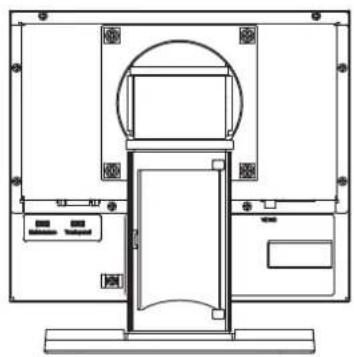
Outside Dimensions
unit : mm (inch)
FDX1001T / FDV1001T


natural_image
Technical line drawing of a mechanical or electrical component with no visible text, numbers, or symbols.FDX1201T


natural_image
Technical line drawing of a mechanical or architectural component with no visible text, numbers, or symbols.Connector Pin Assignment
| Pin No. | Signal | Pin No. | Signal | Pin No. | Signal |
| 1 Red video 6 Red video ground 11 NC* | |||||
| 2 Green video 7 Green video ground 12 Data (SDA) | |||||
| 3 Blue video 8 Blue video ground 13 H. Sync | |||||
| 4 NC* 9 NC* 14 V. Sync | |||||
| 5 Ground 10 Ground 15 Clock (SCL) | |||||
(NC*: No Connection)
- Serial port for the touch panel
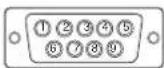
| Pin No. | Signal | Pin No. | Signal |
| 1 DCD 6 DSR | |||
| 2 RXD | 7 RTS | ||
| 3 TXD | 8 CTS | ||
| 4 DTR | 9 RI | ||
| 5 Ground | |||
5-3. Glossary
Afterimage
The Afterimage is particular to LCD monitors. When the monitor screen is left on for a long period without use. The Afterimage can be removed gradually by changing the displayed image.
Clock
The analog input monitor needs to reproduce a clock of the same frequency as the dot clock of the graphics system in use, when the analog input signal is converted to a digital signal for image display. This is called clock adjustment. If the clock pulse is not set correctly, some vertical bars appear on the screen.
Phase
Phase means the sampling timing to convert the analog input signal to a digital signal. Phase adjustment is made to adjust the timing. It is recommended that phase adjustment be made after the clock is adjusted correctly.
Range Adjustment
Range adjustment controls the signal output levels to display every color gradation. It is recommended that range adjustment be made before color adjustment.
Resolution
The LCD panel consists of numerous pixels of specified size, which are illuminated to form images. This monitor consists of 1024 (FDX1001T/FDX1201T) / 640 (FDV1001T) horizontal pixels and 768 (FDX1001T/FDX1201T) / 480 (FDV1001T) vertical pixels. At a resolution of 1024 × 768 (FDX1001T/FDX1201T) / 640 × 480 (FDV1001T), all pixels are illuminated as a full screen (1:1).
5-4. Preset Timing
The following table shows the factory preset video timing of the PC.
ATTENTION
- Display position may be deviated depending on the PC connected, which may require screen adjustment using Setting menu.
- If a signal other than those listed in the table is input, adjust the screen using the Setting menu. However, screen display may still be incorrect even after the adjustment.
- When interlace signals are used, the screen cannot be displayed correctly even after screen adjustment using the Setting menu.
FDX1001T/FDX1201T
| Resolution | Applicable signal | Frequency Polarity | ||||
| Dot clock : MHz | Horizontal : kHz | Vertical : Hz | Horizontal | Vertical | ||
| 720 × 400 VGA | TEXT 28.33 31.4 | 7 70.09 | Negative Positive | |||
| 640 × 480 VGA | 25.18 31.47 59.9 | 4 Negative | Negative | |||
| 640 × 480 VEA | SA 31.50 37.86 72. | 81 | Negative | Negative | ||
| 640 × 480 VEA | SA 31.50 37.50 75. | 00 | Negative | Negative | ||
| 800 × 600 VEA | SA 36.00 35.16 56. | 25 | Positive | Positive | ||
| 800 × 600 VEA | SA 40.00 37.88 60. | 32 | Positive | Positive | ||
| 800 × 600 VEA | SA 50.00 48.08 72. | 19 | Positive | Positive | ||
| 800 × 600 VEA | SA 49.50 46.88 75. | 00 | Positive | Positive | ||
| 1024 × 768 | VESA 65.00 | 48.36 | 60.00 | Negative | Negative | |
| 640 × 480 | MAC 30.24 | 35.00 | 66.67 | Negative | Negative | |
| 832 × 624 | MAC 57.28 | 49.72 | 74.55 | Negative | Negative | |
| 640 × 400 | PC-9801 | 21.05 | 24.83 | 56.42 | Negative | Negative |
| 640 × 400 | PC-9821 AP2 | 25.18 | 31.48 | 70.10 | Negative | Negative |
FDV1001T
| Resolution | Applicable signal | Frequency Polarity | ||||
| Dot clock : MHz | Horizontal : kHz | Vertical : Hz | Horizontal | Vertical | ||
| 720 × 400 VGA | TEXT 28.33 31.47 | 70.09 Negative Positive | ||||
| 640 × 480 VGA | 25.18 31.47 59.94 | Negative Negative | ||||
| 800 × 600 VESA | 36.00 35.16 56.25 | Positive Positive | ||||
| 800 × 600 VESA | 40.00 37.88 60.32 | Positive Positive | ||||
| 1024 × 768 | VESA 65.00 | 48.36 60.00 Negative Negative | ||||
| 640 × 480 | MAC 30.24 | 35.00 66.67 Negative Negative | ||||
| 640 × 400 | PC-9801 | 21.05 24.83 | 56.42 Negative Negative | |||
| 640 × 400 | PC-9821 AP2 | 25.18 31.48 | 70.10 Negative Negative | |||
LIMITED WARRANTY
EIZO NANAO CORPORATION (hereinafter referred to as "EIZO") and distributors authorized by EIZO (hereinafter referred to as the "Distributors") warrant, subject to and in accordance with the terms of this limited warranty (hereinafter referred to as the "Warranty"), to the original purchaser (hereinafter referred to as the "Original Purchaser") who purchased the product specified in this document (hereinafter referred to as the "Product") from EIZO or Distributors, that EIZO and Distributors shall, at their sole discretion, either repair or replace the Product at no charge if the Original Purchaser becomes aware within the Warranty Period (defined below) that the Product malfunctions or is damaged in the course of normal use of the Product in accordance with the description in the instruction manual attached to the Product (hereinafter referred to as the "User's Manual").
The period of this Warranty is two (2) years from the date of purchase of the Product (hereinafter referred to as the "Warranty Period"). EIZO and Distributors shall bear no liability or obligation with regard to the Product in relation to the Original Purchaser or any third parties other than as provided under this Warranty.
EIZO and Distributors will cease to hold or store any parts of the Product upon expiration of seven (7) years after the production of such parts is discontinued. In repairing the monitor, EIZO and Distributors will use renewal parts which comply with our QC standards.
The Warranty is valid only in the countries or territories where the Distributors are located. The Warranty does not restrict any legal rights of the Original Purchaser.
Notwithstanding any other provision of this Warranty, EIZO and Distributors shall have no obligation under this Warranty whatsoever in any of the cases as set forth below:
(a) Any defect of the Product caused by freight damage, modification, alteration, abuse, misuse, accident, incorrect installation, disaster, faulty maintenance and/or improper repair by third party other than EIZO and Distributors;
(b) Any incompatibility of the Product due to possible technical innovations and/or regulations;
(c) Any deterioration of the sensor;
(d) Any deterioration of display performance caused by the deterioration of expendable parts such as the LCD panel and/or backlight, etc. (e.g. changes in brightness, changes in brightness uniformity, changes in color, changes in color uniformity, defects in pixels including burnt pixels, etc.);
(e) Any defect of the Product caused by external equipment;
(f) Any defect of the Product on which the original serial number has been altered or removed;
(g) Any defect of the Product caused by liquid leaking from battery;
(h) Any normal deterioration of the product, particularly that of consumables, accessories, and/or attachments (e.g. batteries, buttons, rotating parts, remote control, cables, User's Manual, etc.); and
(i) Any deformation, discoloration, and/or warp of the exterior of the product including that of the surface of the LCD panel.
To obtain service under the Warranty, the Original Purchaser must deliver the Product, freight prepaid, in its original package or other adequate package affording an equal degree of protection, assuming the risk of damage and/or loss in transit, to the local Distributor. The Original Purchaser must present proof of purchase of the Product and the date of such purchase when requesting services under the Warranty.
The Warranty Period for any replaced and/or repaired product under this Warranty shall expire at the end of the original Warranty Period.
EIZO OR DISTRIBUTORS ARE NOT RESPONSIBLE FOR ANY DAMAGE TO, OR LOSS OF, DATA OR OTHER INFORMATION STORED IN ANY MEDIA OR ANY PART OF ANY PRODUCT RETURNED TO EIZO OR DISTRIBUTORS FOR REPAIR.
EIZO AND DISTRIBUTORS MAKE NO FURTHER WARRANTIES, EXPRESSED OR IMPLIED, WITH RESPECT TO THE PRODUCT AND ITS QUALITY, PERFORMANCE, MERCHANTABILITY OR FITNESS FOR ANY PARTICULAR USE. IN NO EVENT SHALL EIZO OR DISTRIBUTORS BE LIABLE FOR ANY INCIDENTAL, INDIRECT, SPECIAL, CONSEQUENTIAL OR OTHER DAMAGE WHATSOEVER (INCLUDING, WITHOUT LIMITATION, DAMAGES FOR LOSS OF PROFIT, BUSINESS INTERRUPTION, LOSS OF BUSINESS INFORMATION, OR ANY OTHER PECUNIARY LOSS) ARISING OUT OF THE USE OR INABILITY TO USE THE PRODUCT OR IN ANY CONNECTION WITH THE PRODUCT, WHETHER BASED ON CONTRACT, TORT, NEGLIGENCE, STRICT LIABILITY OR OTHERWISE, EVEN IF EIZO OR DISTRIBUTORS HAVE BEEN ADVISED OF THE POSSIBILITY OF SUCH DAMAGES. THIS EXCLUSION ALSO INCLUDES ANY LIABILITY WHICH MAY ARISE OUT OF THIRD PARTY CLAIMS AGAINST THE ORIGINAL PURCHASER. THE ESSENCE OF THIS PROVISION IS TO LIMIT THE POTENTIAL LIABILITY OF EIZO AND DISTRIBUTORS ARISING OUT OF THIS LIMITED WARRANTY AND/OR SALES.
关于电子信息产品污染控制标识


- 重要事项
- FCC Declaration of Conformity
- Canadian Notice
- SAFETY SYMBOLS
- PRECAUTIONS
- IMPORTANT
- 【Location of Caution Statement】
- Use the unit in an appropriate location.
- To avoid danger of suffocation, keep the plastic packing bags away from babies and children.
- Use the enclose AC adapter.
- Make sure the power cord meets the following requirements.
- To disconnect the power cord, grasp the plug firmly and pull.
- Use the correct voltage.
- Handle the power cord and AC adapter with care.
- Never touch the plug, AC adapter or power cord during a thunderstorm.
- When attaching an arm stand, please refer to the user's manual of the arm stand and install the unit securely.
- CAUTION
- Notice for this monitor
- Cleaning
- ATTENTION
- NOTE
- To use the monitor comfortably
- CONTENTS
- PRECAUTIONS 3
- CONTENTS 8
- Chapter 1 Introduction ...... 9
- Chapter 2 Connecting Cables.... 11
- Chapter 3 Settings and Adjustments .... 15
- Chapter 4 Troubleshooting .... 19
- Chapter 5 Reference ...... 21
- LIMITED WARRANTY 30
- Chapter 1 Introduction
- 1-1. Features
- 1-2. Package Contents
- 1-3. Controls and Functions
- Chapter 2 Connecting Cables
- 2-1. Connection Procedures
- Connects to external equipment compatible with the monitor.
- - When used as a PC monitor
- Compatible Resolutions/Frequencies
- - When using video equipment
- Plug the power cord of the monitor into a power outlet.
- 2-2. Adjusting the Screen Angle
- 2-3. Installing the Touch Panel Driver
- 2-4. Calibrating the Monitor
- Chapter 3 Settings and Adjustments
- 3-1. Basic Operation and Functions
- Displaying Setting Menu
- Setting/Adjusting
- Exiting
- Functions
- 3-2. Color Adjustment
- 3-3. Configure other settings
- Chapter 4 Troubleshooting
- Chapter 5 Reference
- 5-1. Attaching an Arm
- [Attachment Procedure]
- 5-2. Specifications
- Outside Dimensions
- Connector Pin Assignment
- 5-3. Glossary
- Afterimage
- Clock
- Phase
- Range Adjustment
- Resolution
- 5-4. Preset Timing
- LIMITED WARRANTY
- 关于电子信息产品污染控制标识
Brand : EIZO
Model : DuraVision FDX1201T
Category : Screen