MP-25 - Blender Rane - Free user manual and instructions
Find the device manual for free MP-25 Rane in PDF.

| Product Type | Blender |
| Brand | Rane |
| Model | MP-25 |
| Capacity | 1.5 liters |
| Power | 500 watts |
| Speed Settings | 2 speeds plus pulse |
| Blade Material | Stainless steel |
| Jar Material | BPA-free plastic |
| Dimensions (H x W x D) | 40 cm x 20 cm x 20 cm |
| Weight | 2.0 kg |
| Cord Length | 1.2 meters |
| Voltage | 220-240 V, 50/60 Hz |
| Functions | Blending, crushing ice, mixing |
| Cleaning | Wipe with damp cloth; jar is dishwasher safe |
| Safety Features | Overload protection, non-slip base |
| Spare Parts | Replacement jar and blade assembly available |
| Warranty | 1 year limited warranty |
Frequently Asked Questions - MP-25 Rane
User questions about MP-25 Rane
0 question about this device. Answer the ones you know or ask your own.
Ask a new question about this device
Download the instructions for your Blender in PDF format for free! Find your manual MP-25 - Rane and take your electronic device back in hand. On this page are published all the documents necessary for the use of your device. MP-25 by Rane.
USER MANUAL MP-25 Rane
text_image
MIC 1 BOOTH LEVEL PHONES LEVEL PAN PAN PHONES LEVEL LOW FLEXFX FLEXFX CUE SPLIT CUE MIC ON TALKOVER TALKOVER MIC 2 LEVEL PAH PAH PAN PAN PAN FLEXFX FLEXFX CUE FLEXFX MIC ON TALKOVER FLEXFX FLEXFX FLEXFX FLEXFX ON CUE FLEXFX CUE FLEXFX CUE FLEXFX FLEXFX FLEXFX ON CUE FLEXFX FLEXFX FLEXFX ON CUE FLEXFX FLEXFX FLEXFX ON CUE FLEXFX FLEXFX FLEXFX ON CUE FLEXFX FLEXFX FLEXFX ON CUE FLEXFX FLEXFX FLEXFX ON CUE FLEXFX FLEXFX FLEXFX ON CUE FLEXFX FLEXFX FLEXFX ON MAYA CONTOUR A B POM 1 D0 A1.62 A9 A4P D0 A1.62 A9 A4P D0 A1.62 A9 A4P D0 A1.62 A9 A4P D0 A1.62 A9 A4P D0 A1.62 A9 A4P D0 A1.62 A9 A4P D0 A1.62 A9 A4P D0 A1.62 B3 A4 P2 A4 P2 A4 P2 A4 P2 A4 P2 A4 P2 A4 P2 A4 P2 A4 P2 A4 P2 A4 P2 A4 P2 A4 P2 A4 P2 A4 P2 A4 P2 A4 P2 A4 P2 A4 P2 A4 P2 A4 P2 A4 P2 A4 P2 A4 P2 A4 P2 A4 P3 D0 A1.62 B3 A4 P2 A4 P2 A4 P2 A4 P2 A4 P2 A4 P2 A4 P2 A4 P2 A4 P2 A4 P2 A4 P2 A4 P2 A4 P2 A4 P2 A4 P2 A4 P2 A4 P2 A4 P2 A4 P2 A4 P2 A4 P2 A4 P2 A5 D0 A1.62 B3 A4 P2 A4 P2 A4 P2 A4 P2 A4 P2 A4 P2 A4 P2 A4 P2 A4 P2 A4 P2 A4 P2 A4 P2 A4 P2 A4 P2 A4 P2 A4 P2 A4 P2 A4 P2 A4 P2 A4 P2 A5 D0 A1.62 B3 A4 P2 A4 P3 A4 P3 A4 P3 A4 P3 A4 P3 A4 P3 A4 P3 A4 P3 A4 P3 A4 P3 A4 P3 A4 P3 A4 P3 A4 P3 A4 P3 A4 P3 A4 P3 A5 D0 A1.62 B3 SOUTURE HIGH SOURCE HIGH SOURCE HIGH SOURCE HIGH SOURCE HIGH SOURCE HIGH SOURCE HIGH SOURCE HIGH SOURCE HIGH SOURCE HIGH SOURCE HIGH SOURCE HIGH SOURCE HIGH SOURCE HIGH SOURCE HIGH SOURCE HIGH SOURCE HIGH SOURCE HIGH SOURCE HIGH SOURCE HIGH SOURCE HIGH SOURCE HIGH SOURCE HIGH SOURCE HIGH SOURCE HIGH SOURCE HIGH SOURCE HIGH SOURCE HIGH SOURCE HIGH SOURCE HIGH SOURCE HIGH SOURCE HIGH SOURCE HIGH SOURCE HIGH SOURCE HIGH SOURCE HIGH SOURCE HIGH SOURCE HIGH SOURCE HIGH SOURCE HIGH SOURCE HIGH SOURCE HIGH SOURCE HIGH SOURCE HIGH SOURCE HIGH SOURCE HIGH SOURCE HIGH SOURCE HIGH SOURCE HIGH SOURCE HIGH SOURCE HIGH | FLEXFX SEND EXT LOOP USB LOOP RETURN CUE LEVEL Return MOND VOLTAGE RIGHT BALANCE FLEXFX MP25 CLUB MIXERContents
Important Safety Instructions 2
Specifications 4
General Description 5
Connecting the Mixer 6
Mixer Controls 8
USB Drivers 11
Software 13
Faders 14
Sound System Interconnection 15
How-to Properly Set Level Controls 23
Declaration of Conformity 25
Warranty 26
Important Safety Instructions
-
Read these instructions.
-
Keep these instructions.
-
Heed all warnings.
-
Follow all instructions.
-
Do not use this apparatus near water.
-
Clean only with a dry cloth.
-
Do not block any ventilation openings. Install in accordance with manufacturer's instructions.
-
Do not install near any heat sources such as radiators, registers, stoves, or other apparatus (including amplifiers) that produce heat.
-
Do not defeat the safety purpose of the polarized or grounding-type plug. A polarized plug has two blades with one wider than the other. A grounding-type plug has two blades and a third grounding prong. The wide blade or third prong is provided for your safety. If the provided plug does not fit into your outlet, consult an electrician for replacement of the obsolete outlet.
-
Protect the power cord and plug from being walked on or pinched particularly at plugs, convenience receptacles, and the point where it exits from the apparatus.
-
Only use attachments and accessories specified by Rane.
-
Use only with the cart, stand, tripod, bracket, or table specified by the manufacturer, or sold with the apparatus. When a cart is used, use caution when moving the cart/apparatus combination to avoid injury from tip-over.
-
Unplug this apparatus during lightning storms or when unused for long periods of time.
-
Refer all servicing to qualified service personnel. Servicing is required when the apparatus has been damaged in any way, such as power supply cord or plug is damaged, liquid has been spilled or objects have fallen into the apparatus, the apparatus has been exposed to rain or moisture, does not operate normally, or has been dropped.
-
The plug on the power cord is the AC mains disconnect device and must remain readily operable. To completely disconnect this apparatus from the AC mains, disconnect the power supply cord plug from the AC receptacle.
-
This apparatus shall be connected to a mains socket outlet with a protective earthing connection.
-
When permanently connected, an all-pole mains switch with a contact separation of at least 3 mm in each pole shall be incorporated in the electrical installation of the building.
-
If rackmounting, provide adequate ventilation. Equipment may be located above or below this apparatus, but some equipment (like large power amplifiers) may cause an unacceptable amount of hum or may generate too much heat and degrade the performance of this apparatus.
-
This apparatus may be installed in an industry standard equipment rack. Use screws through all mounting holes to provide the best support.
WARNING: To reduce the risk of fire or electric shock, do not expose this apparatus to rain or moisture. Apparatus shall not be exposed to dripping or splashing and no objects filled with liquids, such as vases, shall be placed on the apparatus.
WARNING

CAUTION
RISK OF ELECTRIC SHOCK DO NOT OPEN

ATTENTION: RISQUE DE CHOCS ELECTRIQUE - NE PAS OUVRIR
To reduce the risk of electrical shock, do not open the unit. No user serviceable parts inside. Refer servicing to qualified service personnel.
The symbols shown below are internationally accepted symbols that warn of potential hazards with electrical products.

This symbol indicates that a dangerous voltage constituting a risk of electric shock is present within this unit.

This symbol indicates that there are important operating and maintenance instructions in the literature accompanying this unit.
WARNING: This product may contain chemicals known to the State of California to cause cancer, or birth defects or other reproductive harm.
NOTE: This equipment has been tested and found to comply with the limits for a Class B digital device, pursuant to part 15 of the FCC Rules. These limits are designed to provide reasonable protection against harmful interference in a residential installation. This equipment generates, uses and can radiate radio frequency energy and, if not installed and used in accordance with the instructions, may cause harmful interference to radio communications. However, there is no guarantee that interference will not occur in a particular installation. If this equipment does cause harmful interference to radio or television reception, which can be determined by turning the equipment off and on, the user is encouraged to try to correct the interference by one or more of the following measures:
- Reorient or relocate the receiving antenna.
- Increase the separation between the equipment and receiver.
- Connect the equipment into an outlet on a circuit different from that to which the receiver is connected.
- Consult the dealer or an experienced radio/TV technician for help.
CAUTION: Changes or modifications not expressly approved by Rane Corporation could void the user's authority to operate the equipment.
This Class B digital apparatus complies with Canadian ICES-003.

| Parameter Specification | |
| Phono/Line, Aux, FlexFX Inputs 4 stereo unbalanced RCA jacks.....Phono or Line Level Rear panel switch for each Phono/Line input.....Phono Response RIAA curve ±1 dB, Gain = 36 dB @ 1 kHz.....Max Phone Input 63 mV @ 1 kHz.....Max Line Input 4 VrmsMic Inputs Balanced 1⁄4" TRS & XLR combination jacks.....Mic 1 Front and rear panel jacks.....Mic 2 Rear panel jack with Mic/Line-level switch.....Max Input (Mic Level) 185 mVrms (-12.5 dBu).....Max Input (Line Level) 3.7 Vrms (13.6 dBu).....EIN (Equivalent Input Noise)FlexFX.....Send.....ReturnOutputs: Main, Zone, Booth, Record, FlexFX.....Frequency Response.....THD+N.....Max Output (RCA and Unbalanced 1⁄4" TS).....Max Output (XLR and Balanced 1⁄4" TRS).....Zone/Booth.....Main OutputDynamic Range, Line Input to Line OutputAnalog to Digital Converters (ADCs)Digital to Analog Converters (DACs)Digital Signal Processing (DSP)USB Audio.....Stereo Record Channels.....Stereo Playback ChannelsUniversal Internal Power SupplyUSB PowerUnit: Conformity......Construction......Size (Inches)......Size (Metric) 17.8 cm x 48.3 cm x 11.7 cm......WeightShipping: Size (inches)......Size (metric)......WeightNotes: 0 dBu=0.775 Vrms. All specifications are typical unless otherwise stated. | |

text_image
BOOTH LEVEL PHONES LEVEL PAN LOW FLEXFX MIC ON TALKOVER TALKOVER MIC 1 LEVEL PAR HIGH LOW FLEXFX CUE FLEXFX MIC ON TALKOVER MIC 2 LEVEL PAR HIGH LOW FLEXFX CUE FLEXFX MIC ON TALKOVER PAN LEVEL PAR HIGH LOW FLEXFX CUE FLEXFX MIC ON TALKOVER PGM 1 SOURCE HIGH A B POST FILTER A B POST PGM 2 SOURCE HIGH A B POST FILTER A B POST PGM 3 SOURCE HIGH A B POST FILTER A B POST PGM 4 SOURCE HIGH A B POST FILTER A B POST PGM 4 SOURCE HIGH A B POST FILTER A B POST PGM 5 SOURCE HIGH A B POST FILTER A B POST PGM 6 SOURCE HIGH A B POST FILTER A B POST PGM 7 SOURCE HIGH A B POST FILTER A B POST PGM 8 SOURCE HIGH A B POST FILTER A B POST PGM 9 SOURCE HIGH A B POST FILTER A B POST PGM 10 SOURCE HIGH A B POST FILTER A B POST PGM 11 SOURCE HIGH A B POSTGeneral Description
Meet the Rane MP25 mixer, satisfying the audio and ergonomic demands of performing DJs, in a 19" rack format preferred by nightclubs, with a compact 4U design that drops easily into a mobile rig. It's the same size as a classic Rane MM 8z, MP 24 or MP 22 series Mixer.
Sporting two microphone inputs, four studio-grade phono preamps, four analog aux inputs, four low-latency stereo USB inputs, analog and USB effects insert loops, and a variety of analog and digital outputs; the MP25 remains rooted in analog tradition while reaching new heights of digital connectivity.
Reliable, low-latency, multi-client ASIO and Core Audio drivers interface the MP25's twenty-two USB audio channels directly to your favorite multi-track mixing, beat-making, looping, effects, and recording applications. Additionally, the MP25's front panel controls are MIDI enabled, allowing manipulation of software parameters directly from the mixer's control surface.
Features
INPUTS
- Four individually switchable stereo Phono/Line inputs.
- Four stereo Auxiliary inputs.
- Four stereo USB playback inputs.
- Two microphone inputs with optional Talkover ducking:
• One with front and rear panel connectors. - One with a line-level input option.
WEAR PARTS
This product contains no wear parts as described in the Warranty.
OUTPUTS
- Stereo Main Outputs on balanced XLR and unbalanced RCA:
- Rear panel Mono/Stereo switch.
- Rear panel Max Out level attenuator.
- Stereo balanced 14'' TRS Zone and Booth outputs:
• Auto-mono output on both Left and Right jacks.
• Stereo Record outputs on RCA, S/PDIF and USB.
USB
- Four stereo playback channels stream audio directly from your favorite playback, mixing, beat-making, and looping applications to the MP25's digital mixer engine.
- Four stereo record channels stream the four post-fader program channels to your audio application for multi-track recording. A fifth stereo record channel streams Mic 1, Mic 2, or the Main Mix to your recording application.
- The USB Effects Loop enables insertion of stereo computer-based effects processors into the MP25's powerful FlexFX bus.
- Low-latency ASIO / Core Audio drivers eliminate delay between the control input to audio software and the audible result.
- Most of the leading DJ and DAW applications are supported with ASIO / Core Audio drivers. Multiple software applications can simultaneously stream audio to and from the mixer.
- The MP25 MIDI device exposes the MP25 front panel as a MIDI controller, allowing control of audio application parameters using the mixer's control surface.
text_image
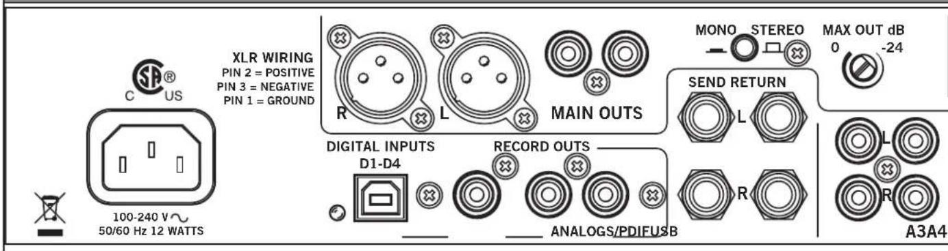
XLR WIRING PIN 2 = POSITIVE PIN 3 = NEGATIVE PIN 1 = GROUND MIN OUTS DIGITAL INPUTS D1-D4 RECORD OUTS ANALOGS/PDIFUSB MONO STEREO SEND RETURN 0 -24 MAX OUT dB A3A4 100-240 V~ 50/60 Hz 12 WATTSThere's no "Quick Start" here, we recommend you read this relatively short manual to get all this mixer is capable of.
Connecting the Mixer
Leave the power unplugged until everything else is connected
Inputs
Phono/Line Inputs (P1-P4)
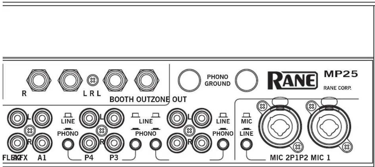
The MP25 has four stereo Phono/Line inputs (P1, P2, P3, P4). Any of these analog inputs may be set for Phono Input or Line Input (for CD players) using the push switches located on the rear panel. Unused inputs are best set to Line. Attach your turntable's ground wires to the Phono Ground connectors. Each of the four program strips has access to one of the Phono/Line Inputs using the program strip's Source selector.
Auxiliary Inputs (A1-A4)
The MP25 has four stereo Auxiliary analog inputs (A1, A2, A3, A4). Each of the four program strips has access to all of the Auxiliary Inputs using the program strip's Source selector.
Mic Inputs (MIC 1 and MIC 2)
The Mic Inputs accept XLR 3-pin plugs, balanced 14 " TRS (tip-ring sleeve) plugs or unbalanced TS (tip-sleeve) plugs. Mic 1 has two input jacks, one on the front panel and one on the rear. Only use one Mic 1 input jack at a time. Mic 2 has a switchable line-level option.
Outputs
Main/Zone/Booth
All analog outputs come from the same "Main Mix" signal. Main, Booth and Zone Outputs each have their own Level control.
The Main output is from unbalanced RCA and balanced XLR jacks with pin 2 "hot" per AES standards (XLR preferred*). If the Main output feeds a mono PA system, engage the Mono switch on the rear of the MP25. If the Main output is able to clip the input to the PA system when the front panel Main Level control is at maximum, reduce the maximum output level using the rear panel Max Out control.
The Booth and Zone outputs are from balanced 14 "TRS (tip-ring-sleeve) jacks. Booth and Zone outputs include auto-mono on both left and right connections. Plug in only one side to receive a mono signal. Plug into both jacks to receive a stereo signal.
*Rane recommends balanced wiring for the strongest signal and rejection of hum and noise. If your cable to the amp rack is less than 10 feet (3 meters), you can usually get away with an unbalanced cable with RCA or 14 TS (tip-sleeve) plugs. If it's longer than that, use balanced XLR and/or TRS cables. See the RaneNote "Sound System Interconnection" included with this manual or at rane.com for details on cable wiring. See "Sound System Interconnection" on page 15.
Record Outputs
Record outputs are a direct feed from the main mix. There are no level controls between the mix and these outputs. The main mix is available in three different formats for recording: unbalanced analog RCA, 24-bit 48 kHz S/PDIF, and USB (on record channel six).
text_image
R L R L BOOTH OUTZONE OUT PHONO GROUND RANE MP25 RANE CORP. L LINE PHONO P4 P3 FLEX A1 PHONO PHONO R R PHONO PHONO R MIC LINE MIC 2P1P2 MIC 1FlexFX Send/Return
The MP25's FlexFX Loop includes an analog insert loop for use with outboard effects processors. The Send and Return signals are on stereo unbalanced 14 " TS jacks. The Left and Right Send jacks provide auto-mono operation. Simply plug in one side for mono, or both sides for stereo. The Return jack provides similar operation. Plugging into either the left or right return jack sends the signal to both the left and right FlexFX Loop return channels. Plugging into both jacks separates the left and right return channels.
USB
Connect your computer to the USB port on the MP25 to send up to twenty-two channels of audio to/from your favorite multi-track mixing, beat-making, looping, sampling, and recording software applications. Install the MP25 ASIO (Windows) or Core Audio (Macintosh) drivers (instructions later in this manual), so that your computer recognizes the MP25.
Digital Inputs
The MP25's USB audio interface includes five stereo playback channels. Playback channels are audio streams from the computer to the MP25. Four of these five channels are D1-D4, the MP25's digital program inputs. Each of the four program strips has access to one of the four digital input channels using the Source selector on the program strip. The fifth stereo playback channel is the return channel of the FlexFX USB insert loop.
Digital Outputs
The MP25's USB audio interface includes six stereo record channels. Record channels are audio streams from the MP25 to the computer. Four of these five channels are post-fader record channels from the MP25's program strips. These four record streams may be used to multi-track record your set for post-production editing and mix-down. The fifth USB record channel is the send channel of the FlexFX USB insert loop. The sixth record channel may be used to record the Main Mix (default), Mic 1, or Mic 2. Select the record source for USB record channel 6 using the MP25 driver control panel on your computer.
MIDI
In addition to being an audio interface, the MP25 front panel is also a USB MIDI controller. The Zone Level, Main Balance and Main Level controls are the only front panel controls not MIDI enabled. See MIDI Implementation later in this manual.
Power Supply
The MP25 features an internal universal switching power supply that operates on any AC mains 100 to 240 VAC, 50 or 60 Hz (most places in the world). All that is required when traveling between different countries is the appropriate power cord, which is usually readily available.

text_image
MIC 1 4 - 6 2 0 10 LEVEL BOOTH 4 - 6 2 0 8 LEVEL PHONES 4 - 6 2 0 8 LEVEL CUE MAIN PAN SPLIT CUE TALKOVER MIC 2 4 - 6 2 0 10 LEVEL OFF +5 HIGH OFF +6 HIGH OFF +6 LOW FLEXFX CUE FLEXFX MIC ON TALKOVER MIC 1 A1 A2 D1 D2 P1 A4 OFF +6 SOURCE 4 - 6 2 0 8 LEVEL OFF +6 MID HIGHLOW OFF +6 A B POST FLEXFX FL-FEXX FL-FEXX CUE FLEXFX MIC ON TALKOVER A B POST HIGLOW OFF +6 FILTER A B POST FLEXFX FL-FEXX FL-FEXX CUE FLEXFX MIC ON TALKOVER A B POST PGM 1 A1 A2 D2 A3 P2 A4 SOURCE 4 - 6 2 0 8 LEVEL OFF +6 MID HIGHLOW OFF +6 FILTER A B POST FLEXFX FL-FEXX FL-FEXX CUE FLEXFX MIC ON TALKOVER A B POST HIGLOW OFF +6 FILTER A B POST PGM 2 A1 A2 D3 A3 P3 A4 SOURCE 4 - 6 2 0 8 LEVEL OFF +6 MID HIGHLOW OFF +6 FILTER A B POST FLEXFX FL-FEXX FL-FEXX CUE FLEXFX MIC ON TALKOVERMixer Controls
Mic Inputs
Two Microphone Inputs are fully independent, each with these controls:
- Level control.
• Pan the signal from Left to Right. - High / Low 2-band, full-cut tone controls. The range is Off to +6 dB, with unity gain at 12 o'clock.
- FlexFX Assign takes the signal out of the Main Mix and sends it to the FlexFX Loop.
- Mic On adds the Mic to the Main Mix as a program input. If Talkover is engaged on the other Mic, this Mic is ducked like any other program input.
- Talkover engages the Mic in the Main Mix and ducks all program inputs. If Talkover is engaged on the other Mic, this Mic is not ducked.
- Peak signal / rms meter displays the signal level with peak-hold.
- Mic 1 front panel connector is intended for a wired dynamic mic. A gooseneck mic is not recommended as it could damage the jack and not be covered under Rane's Warranty.
- Mic 2 allows selection of a Mic- or Line-level input via the rear panel switch. Line-level is usually for wireless mics.
- Mic 1, Mic 2, or the Main Mix may be recorded via USB Record-6. Record source selection is made in the computer's MP25 driver control panel.
Program Strips
Four program input strips include the following controls:
- Source selection: Each program input x may select from Px , Dx , A1, A2, A3, or A4.
- Level adjustment is Off to +12 dB, with unity gain at 12 o'clock.
- High / Mid / Low 3-band, full-cut tone control range is Off to +6 dB, with unity gain at 12 o'clock.
• Filter with Low-pass and High-pass:
- Flat response is in the center at 12 o'clock.
- Low-pass filter cut-off moves from 20 kHz toward 20 Hz as the knob is turned counter-clockwise.
- High-pass filter cut-off moves from 20 Hz toward 20 kHz as the knob is turned clockwise.
-
The filter resonance can be switched high or low in the computer's MP25 driver control panel.
-
The A-B-Post switch assigns the program channel to A-side, B-side, or Post-Crossfader.
- FlexFX assign takes the channel out of the Main Mix and sends it to the FlexFX Bus (post-fader).
- Cue select assigns the channel to the headphones (pre-fader).
- Peak signal / rms meter displays a mono signal level with peak-hold.
- A 60 mm long-throw program fader controls the level of the program channel in the Main Mix.
- PGM 1-4 post-fader, stereo program channels are streamed to the computer via USB record channels 1-4. These channels may be recorded for post production editing and mix-down.
Phones
The Headphone Monitor provides stereo or mono Split Cue operation.
- In Stereo operation, the Pan control pans between stereo Cue and the stereo Main Mix.
- In Split Cue operation, the Pan control pans between Mono Cue in the left ear and mono Main Mix in the right ear.
- Individual Cue buttons are provided for PGM 1, PGM 2, PGM 3, PGM 4 and the FlexFX Loop.
- The Headphone Level control sets the level in both the front panel 3.5 mm and 14 " output jacks.
- The headphone output includes 2-band full-cut tone controls. Tone control range is Off to +6 dB. These headphone tone controls are adjusted from the computer using the MP25 driver control panel.
Main Mix and Main/Zone Outputs
The Main Mix is made from MIC 1, MIC 2, PGM 1, PGM 2, PGM 3, PGM 4 and the FlexFX Mix.
- Mono the Main Mix by pressing the front panel Mono button. To mono only a specific output, use the rear panel Mono switch on the Main Outs, or the auto-mono single plug feature of the Zone and Booth Outs.
- Apply effects to the entire Main Mix by engaging the Main Mix (blue) FlexFX button. This button instantly sends PGMs 1-4 and Mic 1-2 to the FlexFX Bus.
- The Main Mix is metered using a stereo rms/peak signal meter with peak-hold.
The Main Mix feeds these outputs:
- Main Outs
- Front panel Balance and Level controls manage the relative (left/right) and overall levels respectively.
- The rear panel Mono switch combines the left and right channels of the Main output, and an attenuator controls the Max Out dB from 8 Vrms (0 dB) to 0.5 Vrms (-24 dB).
- The Main Output is available on balanced XLR and unbalanced RCA connectors.
- Booth and Zone Outs
- Front panel Booth and Zone Level controls adjust the corresponding output level.
- Booth and Zone Outputs are available on balanced 1/4" TRS jacks. Left and right jacks automatically provide a mono signal if the other plug is not inserted.
- Record Outs
• Stereo unbalanced RCA and S/PDIF outputs.
• The S/PDIF output is a 24-bit 48 kHz digital output.
- The Main Mix, Mic 1, or Mic 2, may be recorded via USB record channel six. Record source selection is made in the computer's MP25 driver control panel.

text_image
FLEXFX 32 4 6 2 8 0 10 SEND EXT LOOP 4 6 2 8 0 10 RETURN CUE 4 6 2 8 0 10 LEVEL FLEXFX ON ZONE 4 6 2 8 0 10 LEVEL MAIN 4 6 2 8 0 10 LEVEL 0L +6 +3 0 -3 -6 -12 -18 LEFT RIGHT BALANCE MONO FLEXFX MP25 CLUB MIXER CONTOUR A BMagnetic Crossfader
The MP25's crossfader is a field replaceable, no-noise, no-bleed magnetic fader.
- Assign each PGM channel to the A-side, B-side or Post-Cross-fader with switches in the program strips.
- Select one of three crossfader slopes with the Contour switch.
Crossfader Questions and Answers
Q: Can I install magnetic crossfaders in any other mixer?
A: The connectors may be similar, but the circuits are very different. Connecting the fader to anything other than the intended cable in the MP25 could permanently damage it.
Q: Can I install another crossfader in my MP25?
A: No. The cable connections are specially designed for Rane magnetic faders.
See "Faders" on page 14.
FlexFX
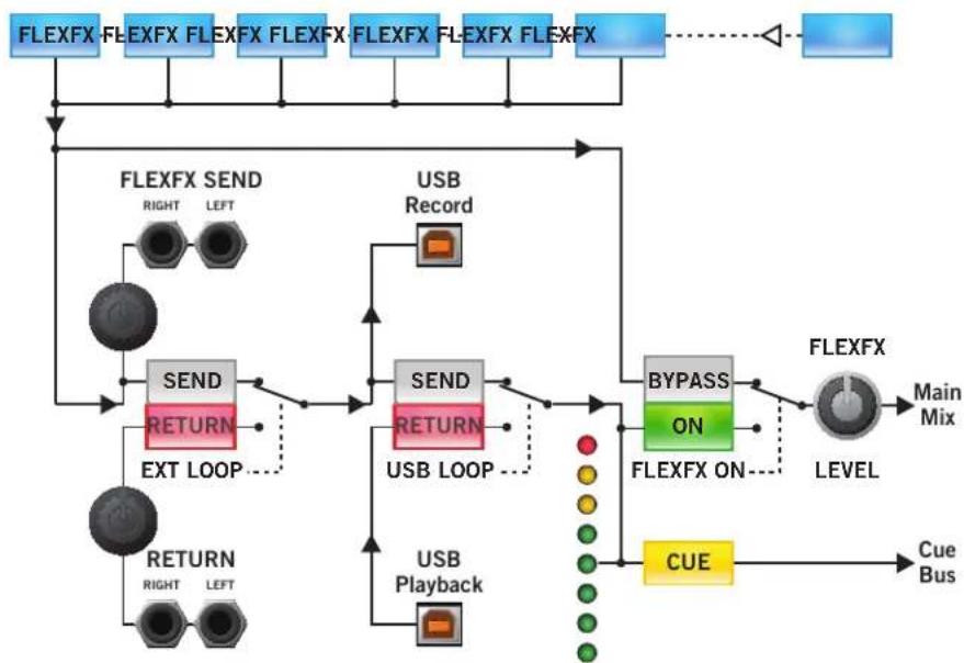
The FlexFX architecture in the MP25 is more powerful than typical effect insert solutions. The architecture includes the FlexFX Bus, an auxiliary bus routed to the FlexFX Loop which includes two independent effects inserts. Any combination of PGM 1-4 and Mic 1-2 may be routed to the FlexFX Bus. Any combination of external analog and USB effects may be applied within the FlexFX Loop. It is possible to cue and meter the FlexFX Loop return. You can bypass the entire FlexFX Loop using a single button to instantly punch in and out a combination of effects. The final FlexFX Output Level controls the level of the FlexFX audio in the Main Mix. The flexibility of the FlexFX architecture makes it a very powerful tool. So, it is important to take some time to understand FlexFX signal routing and controls.
The order of processing in the MP25's FlexFX architecture is:
① Independent FlexFX assign for PGM 1-4 and Mic 1-2, or assign all sources simultaneously with the Main FlexFX button.
② Ext. Analog Insert, with Send and Return Levels.
③USB Insert.
④ FlexFX Loop return Cue and Meter.
⑤ FlexFX On (FlexFX Loop Bypass).
⑥ FlexFX Mix Level control.
① The FlexFX buttons in the PGM and MIC strips assign the post-fader audio to the FlexFX Bus when on, and to the Main Mix when off. This allows multiple inputs to the FlexFX Bus, and allows drumming different signals into and out of an applied effect.
The FlexFX button in the Main Mix section assigns all PGM and Mic channels to the FlexFX Loop, applying effects to the entire mix.
③The USB Loop button engages or bypasses the USB effects insert. The USB insert uses USB record-5 and playback-5 to form an effects loop. Even when the USB insert is bypassed, the audio from the external analog loop is sent to the USB Send. Therefore, when the analog loop is bypassed, USB record-5 can serve as an audio output for recording the FlexFX mix on your computer.
④The FlexFX Cue and Meter are located at the return of the FlexFX Loop, after the analog and USB inserts and before the FlexFX ON switch. This allows cuing the FlexFX mix and any applied effects before they are heard in the Main Mix.
⑤The FlexFX On button toggles between wet and dry versions of the FlexFX mix. When this switch is off, the FlexFX Loop is bypassed and the dry FlexFX mix is routed to the Main Mix. This allows applying and cueing any combination of effects in the FlexFX Loop before hearing those effects in the Main Mix. When you're ready to listen to the affected audio, engage the FlexFX On button (green) and the wet signal is applied to the Main Mix (as long as the FlexFX Level is up).
⑥The FlexFX Level controls the level of the FlexFX audio in the Main Mix. Turn down the FlexFX Level to keep the FlexFX audio out of the Main Mix. Then, you can Cue the FlexFX mix and effects. When the mix is correct and the effects are set up, turn up the FlexFX Level to bring the FlexFX mix into the Main Mix.
②The Ext Loop button engages or bypasses the analog effects insert. Use the Send level to avoid clipping the input of your effects processor. The Return level allows you to bring the signal of the affected output back up to your normal mix level. The FlexFX Bus is always output on the analog loop send, even if Ext Loop is bypassed. This means you may always use the analog Send to record the dry FlexFX mix.
PGM 1 PGM 2 PGM 3 PGM 4MIC 1 MIC 2 MAIN
flowchart
graph TD
    A["FLEXFX"] --> B["FLEXFX SEND"]
    B --> C["SEND"]
    C --> D["RETURN"]
    D --> E["EXT LOOP"]
    E --> F["USB Record"]
    F --> G["SEND"]
    G --> H["RETURN"]
    H --> I["USB LOOP"]
    I --> J["USB Playback"]
    J --> K["BYPASS ON"]
    K --> L["FLEXFX ON"]
    L --> M["FLEXFX"]
    M --> N["LEVEL"]
    N --> O["Main Mix"]
    P["Cue Bus"] --> Q["Cue Bus"]
    R["FLEXFX"] -.-> S["Feedback to FLEXFX"]
USB Drivers
The MP25 includes high-performance, high-stability ASIO and Core Audio device drivers. The driver allows audio applications to play and record audio via the MP25's five stereo playback and six stereo record USB channels. The drivers are designed for incredibly low audio latency, eliminating perceptible delay between control input to audio applications and the resulting audible effect.
Applications may also connect to the MP25 MIDI Out and MIDI In ports. Control changes on the mixer's front panel are sent out the MIDI Out port. Some mixer features may be controlled by sending MIDI messages to the mixer's MIDI In port. Change the MIDI channel number for MIDI In and MIDI Out messages using the driver's control panel.
The driver is available on the MP25 installation CD that is shipped with the mixer. Check for the latest driver from dj.rane.com.
ASIO (Windows)
ASIO
Multi-client ASIO allows different audio software applications to simultaneously stream audio to and from the MP25. If the same playback channel is selected in more than one application, the driver mixes the audio from the different applications before streaming it to the mixer.
Installation
- Connect the MP25 to your computer and power it on.
- Locate the setup executable, either on the installation CD or where you downloaded the driver from www.rane.com.
a. 32-bit Windows: RaneAsioMp25x86Setup.exe
b. 64-bit Windows: RaneAsioMp25x64Setup.exe
c. If you install from the CD that came with your MP25, launch the Rane MP25 Setup.bat file and it automatically chooses the right installer. - Double-click the setup file.
- Follow the prompts on the screen.
- Reboot your PC, and you are ready to go!
Uninstall
The MP25 ASIO drivers may be uninstalled from the Windows control panel. Open the list of installed programs then locate and double-click "Rane MP25."
Windows XP: Start > Control Panel > Add or Remove Programs > Rane MP25.
Windows Vista: Start > Control Panel > Programs and Features > Rane MP25
Windows 7: Start > Control Panel > Programs > Programs and Features > Rane MP25
Launching the Control Panel
The driver control panel may be launched from the Windows Control Panel. Select Start > Control Panel > Rane MP25.
Core Audio (Macintosh)

The MP25 uses a low-latency, Core Audio device driver to interface with applications on Macintosh operating systems.
Installation
- Locate the MP25.pkg file, either on the installation CD or where you downloaded the driver from www.rane.com.
- Double click the package file.
- Follow the prompts on the screen.
- Reboot your Mac, and you are ready to go!
Launching the Control Panel
Open the System Preferences window. Locate the MP25 in the "Other" section, and click the MP25 icon to launch the panel.
Control Panel
The MP25 driver control panel allows you to set some preferences for your MP25 Mixer. There are three pages in the control panel: Preferences, PGM Inputs 1-4, and MIDI Channel Selection. You can switch between these pages by pressing the button in the upper left-hand corner. The button displays the name of the next page.
Preferences
The Preferences page allows you to control these features:
- 2-Band Headphone Tone Controls adjust the level of headphone output high and low frequencies from +6 dB to Off.
- USB-6 Record source selection routes the specified signal within the MP25 to the USB-6 Record channel. The available options are Main Mix, Mic 1, and Mic 2. Main Mix is the default setting.
- Button backlighting is on by default, but may be turned off using the Button Backlight control. When the backlight is on, buttons toggle between dimly lit and fully lit. When the backlight is off, buttons toggle between dark and fully lit.
- The USB driver buffer size may be increased to achieve higher stability at the cost of higher latency. The MP25's drivers are designed to run very reliably at latencies below 10 milliseconds. However, computer performance and available resources (number of applications running) may adversely affect the computer's ability to stream audio reliably. If pops and clicks are heard in the USB audio, try increasing the buffer size to eliminate them.
- If the MP25 firmware installed on your computer is newer than the firmware in your MP25, the Update Device Firmware panel is enabled. Pressing the Update Firmware button will update the MP25 firmware to the newer version installed with your driver.
PGM1-4 Inputs
- The Filter controls on the program strips each have two Filter Resonance values. The Filter resonance may be set High or Low using the control panel.
MIDI Channel Selection
The MP25's front panel controls are MIDI enabled. Changes to front panel controls may be sent via MIDI to audio applications on the computer. By default, the MP25 uses MIDI channel 1 to send MIDI messages. However, you can change the output channel number using the MIDI Out control. Some MP25 features may be controlled via MIDI. By default, the MP25 does not accept MIDI input. However, you can enable MIDI input to the MP25 by setting the MIDI In channel number.
MIDI Out Controls
All MP25 front panel controls with the exception of the Main Balance, Main Level, and Zone Level send MIDI output messages when changed.
- Buttons output a MIDI Note On message when pressed and a MIDI Note Off message when released.
- Pots and faders output a MIDI control change message whenever they change value. The value is a number in the range 0 to 127 (counter-clockwise to clockwise, down to up, or left to right).
- Switches produce control change messages when they change value. The following table lists MP25 switches and their control values.
| Switch Control Change Values | |
| PGM Source Selector | 1=Px, 2=Dx, 3=A1, 4=A2,5=A3, 6=A4 |
| Crossfader Assign 1=A, 2=B, 3=Post | |
| Crossfader Contour 1=Slow, 2=Medium, 3=Fast | |
MIDI In Controls
The mixer parameters controlled via the MP25 driver control panel are also available for control via MIDI Input. All MIDI Inputs are control change messages. The following table lists the MP25 MIDI Input parameters and their control values.
| MP25 Parameter Control Change Values | |
| Low/High Headphone Tone Controls | 0-127, 0 = Off, 127 = +6 dB |
| USB-6 Record Source | 1 = Main Mix, 2 = Mic 1,3 = Mic 2 |
| Button Backlight 0 = Off, 1 = Dim | |
| PGM 1-4 High-pass/Low-pass Filter Resonance | 0-64 = Low, 65-127 = High |

text_image
MP25 MIDI Controls Control Change Note On / Off RANE MOBOTH 75 LEVEL PHONES 99 LEVEL CUE ON PAN 56 SPLIT CUE TALKOVER MIC 1 100 LEVEL 88 PAN 94 HIGH 82 LOW 34 FLEXFX 41 MIC ON 46 TALKOVER MIC 2 76 LEVEL 70 PAN 64 HIGH 95 LOW 88 FLEXFX 40 MIC ON 47 TALKOVER PGM 1 116 SOURCE HIGH 89 LEVEL MID 65 A B POST 69 CUE 83 FLEXFX FLEXFX FLEXFX 70 A B POST 84 CUE 85 FLEXFX FLEXFX FLEXFX 120 A B POST 121 FLEXFX FLEXFX FLEXFX 121 A B POST 122 FLEXFX ON 71 CUE 86 FLEXFX 117 SOURCE HIGH 90 LEVEL MID 66 A B POST 67 FLEXFX FLEXFX FLEXFX 121 A B POST 122 FLEXFX ON 62 CUE 86 FLEXFX 103 SOURCE HIGH 91 LEVEL MID 67 A B POST 66 FLEXFX FLEXFX FLEXFX 121 A B POST 122 FLEXFX ON 103 SOURCE HIGH 92 LEVEL MID 73 A B POST 74 FLEXFX FLEXFX FLEXFX 103 SOURCE HIGH 93 A B P2 P3 P4 P5 P6 P7 P8 P9 P10 P11 P12 P13 P14 P15 P16 P17 P18 P19 P20 P21 P22 P23 P24 P25 P26 P27 P28 P29 P30 P31 P32 P33 P34 P35 P36 P37 P38 P39 P40 P41 P42 P43 P44 P45 P46 P47 P48 P49 P50 P51 P52 P53 P54 P55 P56 P57 P58 P59 P60 P61 P62 P63 P64 P65 P66 P67 P68 P69 P70 P71 P72 P73 P74 P75 P76 P77 P78 P79 P80 P81 P82 P83 P84 P85 P86 P87 P88 P89 P90 P91 P92 P93 P94 P95 P96 P97 P98 P99 P100 P101 N/A N/A N/A N/A N/A N/A N/A N/A N/A N/A N/A N/A N/A N/A N/A N/A N/A N/A N/A N/A N/A N/A N/A N/A N/A N/A N/A N/A N/A N/A N/A N/A N/A N/A N/A N/A N/A N/A N/A N/A N/A N/A N/A N/A N/A N/A N/A N/A N/A N/A N/
text_image
MP25 Audio Driver Control Panel MIDI PGM Inputs 1-4 PGM 1 Filter Resonance ● High ● Low 22 PGM 2 Filter Resonance ● High ● Low 25 PGM 3 Filter Resonance ● High ● Low 28 PGM 4 Filter Resonance ● High ● Low 31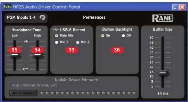
text_image
MP25 Audio Driver Control Panel PGM Inputs 1-4 Preferences Headphone Tone Low High +6 35 34 USB-6 Record Main Mix Mic 1 Mic 2 33 Button Backlight On Off 36 Buffer Size Device Firmware Version: 1.00 Update Firmware 14 msSoftware
Most audio software is compatible with the ASIO and Core Audio drivers included with the MP25, which includes a low-latency, USB 2.0, high-speed, 10-input, 12-output audio interface. The MP25 front panel controls are MIDI-mappable in supporting software.
The MP25 ASIO and Core Audio drivers require the following minimum system:
• PC: Windows XP, Vista, 7 or 8, 32-bit and 64-bit support.
• Mac: OS X 10.5.8 to 10.8.x. 32 bit or 64 bit kernel.
• System Memory: 2 GB or more.
- Processor: 2 GHz single core or better.
Visit the MP25 page at dj.rane.com for the most recent drivers.
Side Dimensions

text_image
1.3" (3.3 cm) 2.9" (7.4 cm) 2.45" (6.2 cm) 6.9" (17.6 cm) .7" (1.8 cm) 3.7" (9.4 cm) 4.4" (11.2 cm)Stereo USB Playback Inputs and Record Outputs

text_image
USB PLAYBACK INPUTS USB 1 PLAYBACK (1-2) D1 MIC 1 LEVEL UPATH PHONES LEVEL PAN HIGH LOW PAN HIGH LOW PAN FLEXFX CUE FLEXFX MIC ON TALKOVER TALKOVER USB RECORD OUTPUTS USB 1 RECORD (1-2) PUMA SOURCE PUMA PUMA PUMA PUMA PUMA PUMA PUMA PUMA PUMA PUMA PUMA PUMA PUMA PUMA PUMA PUMA PUMA PUMA PUMA PUMA PUMA PUMA PUMA PUMA PUMA PUMM PUMM PUMM PUMM PUMM PUMM PUMM PUMM PUMM PUMM PUMM PUMM PUMM PUMM PUMM PUMM PUMM PUMM PUMM PUMM PUMM PUMM PUMM PUMM PUMM PUM MUX PUM MUX PUM MUX PUM MUX PUM MUX PUM MUX PUM MUX PUM MUX PUM MUX PUM MUX PUM MUX PUM MUX PUM MUX PUM MUX PUM MUX PUM MUX PUM MUX PUM MUX PUM MUX PUM MUX PUM MUN PUM MUN PUM MUN PUM MUN PUM MUN PUM MUN PUM MUN PUM MUN PUM MUN PUM MUN PUM MUN PUM MUN PUM MUN PUM MUN PUM MUN PUM MUN PUM MUN PUM MUN PUM MUN PUM MUN PUM MUNDUCKECKECKECKECKECKECKECKECKECKECKECKECKECKECKECKECKECKECKECKECKECKECKECKECKECKECKECKECKECKECKECKECKECKECKECKECKECKECKECKECKECKECKECKECKECKECKECKECKECKECKeCKeCKeCKeCKeCKeCKeCKeCKeCKeCKeCKeCKeCKeCKeCKeCKeCKeCKeCKeCKeCKeCKeCKeCKeCKeCKeCKeCKeCKeCKeCKeCKeCKeCKeCKeCKeCKeCKeCKeCKeCKeCKeCKeCKeCKeCKeCKeCKeCKeCKcPKaMKaMKaMKaMKaMKaMKaMKaMKaMKaMKaMKaMKaMKaMKaMKaMKaMKaMKaMKaMKaMKaMKaMKaMKaMKaMKaMKaMKaMKaMKaMKaMKaMKaMKaMKaMKaMKaMKaMKaMKaMKaMKaMKaMKaMKaMKaMKaMKaMKaMKaNKaMKaMKaMKaMKaMKaMKaMKaMKaMKaMKaMKaMKaMKaMKaMKaMKaMKaMKaMKaMKaMKaMKaMKaMKaMKaMKaMKaMKaMKaMKaMKaMKaMKaMKaMKaMKaMKaMKaMKaMKaMKaMKaMKaMKaMKaMKaMKaMKaMKaRKaNKaNKaNKaNKaNKaNKaNKaNKaNKaNKaNKaNKaNKaNKaNKaNKaNKaNKaNKaNKaNKaNKaNKaNKaNKaNKaNKaNKaNKaNKaNKaNKaNKaNKaNKaNKaNKaNKaNKaNKaNKaNKaNKaNKaNKaNKaNKaNKaNKaNKaNkNkNkNkNkNkNkNkNkNkNkNkNkNkNkNkNkNkNkNkNkNkNkNkNkNkNkNkNkNkNkNkNkNkNkNkNkNkNkNkNkNkNkNkNkNkNkNkNkNkNkO#o#o#o#o#o#o#o#o#o#o#o#o#o#o#o#o#o#o#o#o#o#o#o#o#o#o#o#o#o#o#o#o#o#o#o#o#o#o#o#o#o#o#o#o#o#o#o#o#o#o#O# INTLLENTLENTLENTLENTLENTLENTLENTLENTLENTLENTLENTLENTLENTLENTLENTLENTLENTLENTLENTLENTLENTLENTLENTLENTLENTLENTLENTLENTLENTLENTLENTLENTLENTLENTLENTLENTLENTLENTLENTLENTLENTLENTLENTLENTLENTLENTLENTLENTLENTLENTLEENTLENTLENTLENTLENTLENTLENTLENTLENTLENTLENTLENTLENTLENTLENTLENTLENTLENTLENTLENTLENTLENTLENTLENTLENTLENTLENTLENTLENTLENTLENTLENTLENTLENTLENTLENTLENTLENTLENTLENTLENTLENTLENTLENTLENTLENTLENTLENTLENTLENTLE NT LE NT LE NT LE NT LE NT LE NT LE NT LE NT LE NT LE NT LE NT LE NT LE NT LE NT LE NT LE NT LE NT LE NT LE NT LE NT LE NT LE NT LE NT LE NT LE NT LE NT LE NT LE NT LE NT LE NT LE NT LE NT LE NT LE NT LE NT LE NT LE NT LE NT LE NT LE NT LE NT LE NT LE NT LE NT LE NT LE NT LE NT LE NT LE NT LE NT LE NT LUT LUT LUT LUT LUT LUT LUT LUT LUT LUT LUT LUT LUT LUT LUT LUT LUT LUT LUT LUT LUT LUT LUT LUT LUT LUT LUT LUT LUT LUT LUT LUT LUT LUT LUT LUT LUT LUT LUT LUT LUT LUT LUT LUT LUT LUT LUT LUT LUT LUT L UT LUT LUT LUT LUT LUT LUT LUT LUT LUT LUT LUT LUT LUT LUT LUT LUT LUT LUT LUT LUT LUT LUT LUT LUT LUT LUT LUT LUT LUT LUT LUT LUT LUT LUT LUT LUT LUT LUT LUT LUT LUT LUT LUT LUT LUT LUT LUT LUT LUT L/ATL/ATL/ATL/ATL/ATL/ATL/ATL/ATL/ATL/ATL/ATL/ATL/ATL/ATL/ATL/ATL/ATL/ATL/ATL/ATL/ATL/ATL/ATL/ATL/ATL/ATL/ATL/ATL/ATL/ATL/ATL/ATL/ATL/ATL /ATL/ATL /ATL/ATL /ATL/ATL /ATL/ATL /ATL/ATL /ATL/ATL /ATL/ATL /ATL/ATL /ATL/ATL /ATL/ATL /ATL/ATL /ATL/ATL /ATL/ATL /ATL/ATL /ATL/ATL /ATL/ATL /ATL/ ATL / ATL / ATL / ATL / ATL / ATL / ATL / ATL / ATL / ATL / ATL / ATL / ATL / ATL / ATL / ATL / ATL / ATL / ATL / ATL / ATL / ATL / ATL / ATL / ATL / ATL / ATL / ATL / ATL / ATL / ATL / ATL / ATL / ATL / A TAL / ATL / ATL / ATL / ATL / ATL / ATL / ATL / ATL / ATL / ATL / ATL / ATL / ATL / ATL / ATL / ATL / ATL / ATL / ATL / ATL / ATL / ATL / ATL / ATL / ATL / ATL / ATL / ATL / ATL / ATL / ATL / ATL / ATL | PUMM | PUMM | PUMM | PUMM | PUMM | PUMM | PUMM | PUMM | PUMM | PUMM | PUMM | PUMM | PUMM | PUMM | PUMM | PUMM | PUMM | PUMM | PUMM | PUMM | PUMM | PUMM | PUMM | PUMM | PUMM | PULFX | FLEXFX | CONTOUR | USB 1 RECORD (1-2) USB 2 RECORD (3-4) USB 3 RECORD (5-6) USB 4 RECORD (7-8) USB 5 RECORD (9-10) USB LOOP OFF | AUDIO DRIVER CONTROL PANEL | USB-6 Record | ● Main Mix ● Mic 1 ● Mic 2 USB 6 RECORD (11-12)Rear Dimensions

text_image
XLR WIRING PK 2 = RESTIVE PK 3 = REGATIVE PK 1 = GROUND MIN OUTS MOND STEREO 0 -24 SEND RETURN DIGITAL INPUTS DI-04 RECORD OUTS R L L R L L R L FLEXFX A4 A3 A2 A1 P4 P3 P2 P1 ZONE OUT L R BOOTH OUT L PHONO GROUND RANE MP25 RANE CORE MIC LINE MIC 2 MIC 1 8" (2 cm) EARS 100 240 V/Hz 5899 Hz 12 WATTS 17.4" (44.2 cm) 19" (48.3 cm) 3.675" (9.4 cm)Faders
Maintaining the Magnetic Crossfader
There are no electrical contacts to clean!
The crossfader in the MP25 is designed with materials highly resistant to corrosion and most chemicals. While the crossfader will handle millions of operations, it may become dirty over time. Bad things may be spilled or sprayed into the crossfader. In either case, the crossfader is not damaged and the sound quality is unaffected. Cleaning is only required to maintain the feel of the crossfader.
The crossfader is self-lubricating and with normal use, should not require additional lubrication. If you wish, you can use a light silicone lubricant rated for use with electrical parts. This will help maintain the feel. We recommend Caig DeoxIT Fader-Lube F100 spray lubricant.
Order DeoxIT® F100 from CAIG Laboratories, Inc.
12200 Thatcher Ct.
Poway, CA 92064
Phone 858-486-8388
Fax 858-486-8398
Web www.caig.com
Never use a heavy lubricant or grease. Doing so will not damage the faders, but can undo the feel. If grease was used, it may be removed by following the cleaning instructions.
Crossfader Removal and Replacement
For cleaning and lubrication, follow these directions:
- Required tools: #1 Philips screwdriver and a pair of clean hands.
- Disconnect the power.
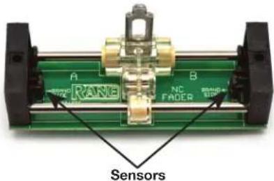
- Remove only the two 4-40 screws attaching the crossover faceplate as pointed out below.

text_image
A B- Remove the crossfader from the mixer, and carefully remove the ribbon cable from the back of the circuit board.
text_image
A B NC FADER Sensors- Move the carrier all the way to one side.
- Use a soft lint-free cloth to wipe off the rails.
- Add a drop of silicone lubricant (or quick spray from aerosol) to the center of each rail.
- Move the carrier back and forth to distribute lubricant.
- Do not bend the torsion spring. Do not disturb the position of the small sensors at each end of the Fader. If you accidentally do, make sure the parts are standing straight before reinstalling.
- CAUTION: Sugary liquids may damage the crossfader beyond repair. You might be able to save it by removing the crossfader and thoroughly rinsing it in hot water. Make sure the part is clean and dry before lubricating or reinstalling.
- Removal of grease or other stubborn debris may require alcohol or contact cleaner. Make sure the part is clean and dry before lubricating or reinstalling.
- Problems? Contact Rane Corporation customer service at 425-355-6000 or email us at info@rane.com.
Channel Fader Cleaning
With heavy use in harsh environments, the channel faders may need lubrication. This treatment extends longevity and can make used faders as good as new. We recommend any of the following cleaning solutions:
• Caig DeoxIT FaderLube F100 spray lubricant
• Caig DeoxIT FaderLube F5 spray cleaner
• CRC 2-26 (www.crcindustries.com)
Order CaiLube MCL from CAIG Laboratories at the same address previously listed.
- Position the fader at mid-travel.
- Spray cleaner/lubricant into both ends of the fader.
- Move the fader over its full travel back and forth a few times.
- Wipe off excess fluid.
If cleaning does not fix sny fader, please contact Rane Corporation customer service at 425-355-6000 or email us at info@rane.com if you are in the U.S.A. Outside the U.S.A, please contact your distributor for service.
Sound System Interconnection
- Cause & prevention of ground loops
• Interfacing balanced & unbalanced
• Proper pin connections and wiring - Chassis ground vs. signal ground
• Ground lift switches
Rane Technical Staff
RaneNote 110
© 1985, 1995, 2006, 2007, 2011 Rane Corporation
Introduction
This note, originally written in 1985, continues to be one of our most useful references. It's popularity stems from the continual and perpetual difficulty of hooking up audio equipment without suffering through all sorts of bizarre noises, hums, buzzes, whistles, etc.— not to mention the extreme financial, physical and psychological price. As technology progresses it is inevitable that electronic equipment and its wiring should be subject to constant improvement. Many things have improved in the audio industry since 1985, but unfortunately wiring isn't one of them. However, finally the Audio Engineering Society (AES) has issued a standards document for interconnection of pro audio equipment. It is AES48, titled "AES48-2005: AES standard on interconnections —Grounding and EMC practices — Shields of connectors in audio equipment containing active circuitry."
Rane's policy is to accommodate rather than dictate. However, this document contains suggestions for external wiring changes that should ideally only be implemented by trained technical personnel. Safety regulations require that all original grounding means provided from the factory be left intact for safe operation. No guarantee of responsibility for incidental or consequential damages can be provided. (In other words, don't modify cables, or try your own version of grounding unless you really understand exactly what type of output and input you have to connect.)
Ground Loops
Almost all cases of noise can be traced directly to ground loops, grounding or lack thereof. It is important to understand the mechanism that causes grounding noise in order to effectively eliminate it. Each component of a sound system produces its own ground internally. This ground is usually called the audio signal ground. Connecting devices together with the interconnecting cables can tie the signal grounds of the two units together in one place through the conductors in the cable. Ground loops occur when the grounds of the two units are also tied together in another place: via the third wire in the line cord, by tying the metal chassis together through the rack rails, etc. These situations create a circuit through which current may flow in a closed “loop” from one unit’s ground out to a second unit and back to the first. It is not simply the presence of this current that creates the hum—it is when this current flows through a unit’s audio signal ground that creates the hum. In fact, even without a ground loop, a little noise current always flows through every interconnecting cable (i.e., it is impossible to eliminate these currents entirely). The mere presence of this ground loop current is no cause for alarm if your system uses properly implemented and completely balanced interconnects, which are excellent at rejecting ground loop and other noise currents. Balanced interconnect was developed to be immune to these noise currents, which can never be entirely eliminated. What makes a ground loop current annoying is when the audio signal is affected. Unfortunately, many manufacturers of balanced audio equipment design the internal grounding system improperly, thus creating balanced equipment that is not immune to the cabling's noise currents. This is one reason for the bad reputation sometimes given to balanced interconnect.
A second reason for balanced interconnect's bad reputation comes from those who think connecting unbalanced equipment into “superior” balanced equipment should improve things. Sorry. Balanced interconnect is not compatible with unbalanced. The small physical nature and short cable runs of completely unbalanced systems (home audio) also contain these ground loop noise currents. However, the currents in unbalanced systems never get large enough to affect the audio to the point where it is a nuisance. Mixing balanced and unbalanced equipment, however, is an entirely different story, since balanced and unbalanced interconnect are truly not compatible. The rest of this note shows several recommended implementations for all of these interconnection schemes.
The potential or voltage which pushes these noise currents through the circuit is developed between the independent grounds of the two or more units in the system. The impedance of this circuit is low, and even though the voltage is low, the current is high, thanks to Mr. Ohm, without whose help we wouldn't have these problems. It would take a very high resolution ohm meter to measure the impedance of the steel chassis or the rack rails. We're talking thousandths of an ohm. So trying to measure this stuff won't necessarily help you. We just thought we'd warn you.
BALANCED OUTPUTS BALANCED INPUTS

text_image
+ - G RED BLACK 2-CONDUCTOR SHIELDED CABLE SHIELD RED BLACK SHIELD + - G FEMALE 2 3 1 1 2-CONDUCTOR SHIELDED CABLE RED BLACK SHIELD MALE FEMALE 2 3 1 T R S CHASSIS GROUND RED BLACK SHIELD 2-CONDUCTOR SHIELDED CABLE RED BLACK SHIELD T R S CHASSIS GROUND SIGNAL GROUNDFigure 1a. The right way to do it.
Interconnection-2
The Absolute Best Right Way To Do It
The method specified by AES48 is to use balanced lines and tie the cable shield to the metal chassis (right where it enters the chassis) at both ends of the cable.
A balanced line requires three separate conductors, two of which are signal (+ and −) and one shield (see Figure 1a). The shield serves to guard the sensitive audio lines from interference. Only by using balanced line interconnects can you guarantee (yes, guarantee) hum-free results. Always use twisted pair cable. Chassis tying the shield at each end also guarantees the best possible protection from RFI [radio frequency interference] and other noises [neon signs, lighting dimmers].
Neil Muncy ^1 , an electroacoustic consultant and seasoned veteran of years of successful system design, chairs the AES Standards Committee (SC-05-05) working on this subject. He tirelessly tours the world giving seminars and dispensing information on how to successfully hook-up pro audio equipment ^2 . He makes the simple point that it is absurd that you cannot go out and buy pro audio equipment from several different manufacturers, buy standard off-the-shelf cable assemblies, come home, hook it all up and have it work hum and noise free. Plug and play. Sadly, almost never is this the case, despite the science and rules of noise-free interconnect known and documented for over 60 years (see References for complete information).
It all boils down to using balanced lines, only balanced lines, and nothing but balanced lines. This is why they were developed. Further, that you tie the shield to the chassis, at the point it enters the chassis, and at both ends of the cable (more on 'both ends' later).
Since standard XLR cables come with their shields tied to pin 1 at each end (the shells are not tied, nor need be), this means equipment using 3-pin, XLR-type connectors must tie pin 1 to the chassis (usually called chassis ground) — not the audio signal ground as is most common.
Not using signal ground is the most radical departure from common pro-audio practice. Not that there is any argument about its validity. There isn't. This is the right way to do it. So why doesn't audio equipment come wired this way? Well, some does, and since 1993, more of it does. That's when Rane started manufacturing some of its products with balanced inputs and outputs tying pin 1 to chassis. So why doesn't everyone do it this way? Because life is messy, some things are hard to change, and there will always be equipment in use that was made before proper grounding practices were in effect.
Unbalanced equipment is another problem: it is everywhere, easily available and inexpensive. All those RCA and 14 " TS connectors found on consumer equipment; effect-loops and insert-points on consoles; signal processing boxes; semi-pro digital and analog tape recorders; computer cards; mixing consoles; et cetera.
The next several pages give tips on how to successfully address hooking up unbalanced equipment. Unbalanced equipment when “blindly” connected with fully balanced units starts a pattern of hum and undesirable operation, requiring extra measures to correct the situation.
The Next Best Right Way To Do It
The quickest, quietest and most foolproof method to connect balanced and unbalanced is to transformer isolate all unbalanced connections. See Figure 2.
Many manufacturers provide several tools for this task, including Rane. Consult your audio dealer to explore the options available.
The goal of these adaptors is to allow the use of standard cables. With these transformer isolation boxes, modification of cable assemblies is unnecessary. Virtually any two pieces of audio equipment can be successfully interfaced without risk of unwanted hum and noise.
COMMON (WRONG) PRACTICE
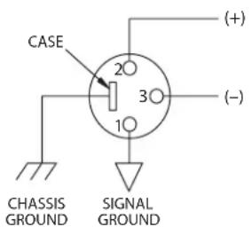
text_image
CASE 20 30 10 CHASSIS GROUND SIGNAL GROUND (+) (-)RECOMMENDED PRACTICE

text_image
CASE OPTIONAL 2 3 1 (+) (-) CHASSIS GROUND CHASSIS GROUNDFigure 1b. Recommended practice.
UNBALANCEDBALANCED
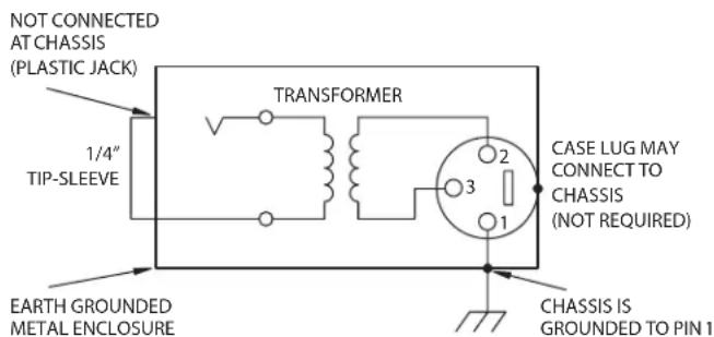
text_image
NOT CONNECTED AT CHASSIS (PLASTIC JACK) 1/4" TIP-SLEEVE TRANSFORMER CASE LUG MAY CONNECT TO CHASSIS (NOT REQUIRED) 2 3 1 EARTH GROUNDED METAL ENCLOSURE CHASSIS IS GROUNDED TO PIN 1Figure 2. Transformer Isolation
Interconnection-3
Another way to create the necessary isolation is to use a direct box. Originally named for its use to convert the high impedance, high level output of an electric guitar to the low impedance, low level input of a recording console, it allowed the player to plug “directly” into the console. Now this term is commonly used to describe any box used to convert unbalanced lines to balanced lines.
The Last Best Right Way To Do It
If transformer isolation is not an option, special cable assemblies are a last resort. The key here is to prevent the shield currents from flowing into a unit whose grounding scheme creates ground loops (hum) in the audio path (i.e., most audio equipment).
It is true that connecting both ends of the shield is theoretically the best way to interconnect equipment – though this assumes the interconnected equipment is internally grounded properly. Since most equipment is not internally grounded properly, connecting both ends of the shield is not often practiced, since doing so usually creates noisy interconnections.
A common solution to these noisy hum and buzz problems involves disconnecting one end of the shield, even though one can not buy off-the-shelf cables with the shield disconnected at one end. The best end to disconnect is the receiving end. If one end of the shield is disconnected, the noisy hum current stops flowing and away goes the hum — but only at low frequencies. A ground-sending-end-only shield connection minimizes the possibility of high frequency (radio) interference since it prevents the shield from acting as an antenna to the next input. Many reduce this potential RF interference by providing an RF path through a small capacitor (0.1 or 0.01 microfarad ceramic disc) connected from the lifted end of the shield to the chassis. (This is referred to as the “hybrid shield termination” where the sending end is bonded to the chassis and the receiving end is capacitively coupled. See Neutrik’s EMC-XLR for example.) The fact that many modern day installers still follow this one-end-only rule with consistent success indicates this and other acceptable solutions to RF issues exist, though the increasing use of digital and wireless technology greatly increases the possibility of future RF problems.
If you've truly isolated your hum problem to a specific unit, chances are, even though the documentation indicates proper chassis grounded shields, the suspect unit is not internally grounded properly. Here is where special test cable assemblies, shown in Figure 3, really come in handy. These assemblies allow you to connect the shield to chassis ground at the point of entry, or to pin 1, or to lift one end of the shield. The task becomes more difficult when the unit you've isolated has multiple inputs and outputs. On a suspect unit with multiple cables, try various configurations on each connection to find out if special cable assemblies are needed at more than one point.
See Figure 4 for suggested cable assemblies for your particular interconnection needs. Find the appropriate output configuration (down the left side) and then match this with the correct input configuration (across the top of the page.) Then refer to the following pages for a recommended wiring diagram.
Ground Lifts
Many units come equipped with ground lift switches. In only a few cases can it be shown that a ground lift switch improves ground related noise. (Has a ground lift switch ever really worked for you?) In reality, the presence of a ground lift switch greatly reduces a unit's ability to be "properly" grounded and therefore immune to ground loop hums and buzzes. Ground lifts are simply another Band-Aid ^® to try in case of grounding problems. It is true that an entire system of properly grounded equipment, without ground lift switches, is guaranteed (yes guaranteed) to be hum free. The problem is most equipment is not (both internally and externally, AC system wise) grounded properly.
Most units with ground lifts are shipped so the unit is “grounded” — meaning the chassis is connected to audio signal ground. (This should be the best and is the “safest” position for a ground lift switch.) If after hooking up your system it exhibits excessive hum or

text_image
FEMALE 2 C 3 1 RED BLACK SHIELD 2-CONDUCTOR SHIELDED CABLE RED BLACK SHIELD MALE 2 3 1 TEST WIRE GROUND CLIP Figure 3. Test cableInterconnection-4
buzzing, there is an incompatibility somewhere in the system's grounding configuration. In addition to these special cable assemblies that may help, here are some more things to try:
- Try combinations of lifting grounds on units supplied with lift switches (or links). It is wise to do this with the power off!
- If you have an entirely balanced system, verify all chassis are tied to a good earth ground, for safety's sake and hum protection. Completely unbalanced systems never earth ground anything (except cable TV, often a ground loop source). If you have a mixed balanced and unbalanced system, do yourself a favor and use isolation transformers or, if you can't do that, try the special cable assemblies described here and expect it to take many hours to get things quiet. May the Force be with you.
- Balanced units with outboard power supplies (wall warts or "bumps" in the line cord) do not ground the chassis through the line cord. Make sure such units are solidly grounded by tying the chassis to an earth ground using a star washer for a reliable contact. (Rane always provides this chassis point as an external screw with a toothed washer.) Any device with a 3-prong AC plug, such as an amplifier, may serve as an earth ground point. Rack rails may or may not serve this purpose depending on screw locations and paint jobs.
Floating, Pseudo, and Quasi-Balancing
During inspection, you may run across a 14 " output called floating unbalanced, sometimes also called psuedo-balanced or quasi-balanced. In this configuration, the sleeve of the output stage is not connected inside the unit and the ring is connected (usually through a small resistor) to the audio signal ground. This allows the tip and ring to "appear" as an equal impedance, not-quite balanced output stage, even though the output circuitry is unbalanced.
Floating unbalanced often works to drive either a balanced or unbalanced input, depending if a TS or TRS standard cable is plugged into it. When it hums, a special cable is required. See drawings #11 and #12, and do not make the cross-coupled modification of tying the ring and sleeve together.
Winning the Wiring Wars
- Use balanced connections whenever possible, with the shield bonded to the metal chassis at both ends.
- Transformer isolate all unbalanced connections from balanced connections.
- Use special cable assemblies when unbalanced lines cannot be transformer isolated.
- Any unbalanced cable must be kept under 10 feet (3 m) in length. Lengths longer than this will amplify all the nasty side effects of unbalanced circuitry's ground loops.
Summary
If you are unable to do things correctly (i.e. use fully balanced wiring with shields tied to the chassis at both ends, or transformer isolate all unbalanced signals from balanced signals) then there is no guarantee that a hum-free interconnect can be achieved, nor is there a definite scheme that will assure noise-free operation in all configurations.
References
- Neil A. Muncy, "Noise Susceptibility in Analog and Digital Signal Processing Systems," presented at the 97th AES Convention of Audio Engineering Society in San Francisco, CA, Nov. 1994.
- Grounding, Shielding, and Interconnections in Analog & Digital Signal Processing Systems: Understanding the Basics; Workshops designed and presented by Neil Muncy and Cal Perkins, at the 97th AES Convention of Audio Engineering Society in San Francisco, CA, Nov. 1994.
- The entire June 1995 AES Journal, Vol. 43, No. 6, available \6 members, \11 nonmembers from the Audio Engineering Society, 60 E. 42nd St., New York, NY, 10165-2520.
- Phillip Giddings, Audio System Design and Installation (SAMS, Indiana, 1990).
- Ralph Morrison, Noise and Other Interfering Signals (Wiley, New York, 1992).
- Henry W. Ott, Noise Reduction Techniques in Electronic Systems, 2nd Edition (Wiley, New York, 1988).
- Cal Perkins, "Measurement Techniques for Debugging Electronic Systems and Their Instrumentation," The Proceedings of the 11th International AES Conference: Audio Test & Measurement, Portland, OR, May 1992, pp. 82-92 (Audio Engineering Society, New York, 1992).
- Macatee, RaneNote: "Grounding and Shielding Audio Devices," Rane Corporation, 1994.
- Philip Giddings, "Grounding and Shielding for Sound and Video," S&VC, Sept. 20th, 1995.
- AES48-2005: AES standard on interconnections — Grounding and EMC practices — Shields of connectors in audio equipment containing active circuitry (Audio Engineering Society, New York, 2005).
Band-Aid is a registered trademark of Johnson & Johnson
From Output
To Input
| CABLE CONNECT |  |  |  |  |  |
| MALE BALANCED XLR | 14" BALANCED TRS (TIP-RING-SLEEVE) | 14" OR 3.5mm UNBALANCED TS (TIP-SLEEVE) | UNBALANCED RCA BALANCED EUROBLOCK | ||
 FEMALE BALANCED XLR(NOT A TRANSFORMER,NOR A CROSS-COUPLED OUTPUT STAGE) FEMALE BALANCED XLR(NOT A TRANSFORMER,NOR A CROSS-COUPLED OUTPUT STAGE) | 1 | 2 | 3B | 4B | + to +- to -SHIELD NC |
 FEMALE BALANCED XLR(EITHER A TRANSFORMER OR A CROSS-COUPLED OUTPUT STAGE) FEMALE BALANCED XLR(EITHER A TRANSFORMER OR A CROSS-COUPLED OUTPUT STAGE) | 1 | 2 | 5 | 6 | + to +- to -SHIELD NC |
 14" BALANCED TRS(NOT A TRANSFORMER,NOR A CROSS-COUPLED OUTPUT STAGE) 14" BALANCED TRS(NOT A TRANSFORMER,NOR A CROSS-COUPLED OUTPUT STAGE) | B | 10987B | + to +- to -SHIELD ONLY TO EUROBLOCK | ||
 14" BALANCED TRS(EITHER A TRANSFORMER OR A CROSS-COUPLED OUTPUT STAGE) 14" BALANCED TRS(EITHER A TRANSFORMER OR A CROSS-COUPLED OUTPUT STAGE) | 121187 | + to +- to -SHIELD NC | |||
 14" FLOATING UNBALANCED TRS (TIP-RING-SLEEVE)(SLEEVE IN UNIT = NC) 14" FLOATING UNBALANCED TRS (TIP-RING-SLEEVE)(SLEEVE IN UNIT = NC) | A | A | 12112221 | + to +- to -GROUND to GROUND | |
 14" OR 3.5 mm UNBALANCED TS (TIP-SLEEVE) 14" OR 3.5 mm UNBALANCED TS (TIP-SLEEVE) | 151413623A | A | |||
 UNBALANCED RCA(TIP-SLEEVE) UNBALANCED RCA(TIP-SLEEVE) | 1918120A | A | 23 | ||
 BALANCED EUROBLOCK BALANCED EUROBLOCK | + to +- to -SHIELD ONLY TO XLR PIN 1 | + to+- to -SHIELD ONLY TO TRS SLEEVE | 24 | 24 | + to+- to -GROUND to GROUND |
Figure 4. Interconnect chart for locating correct cable assemblies on the following pages.
Note: (A) This configuration uses an "off-the-shelf" cable.
Note: (B) This configuration causes a 6 dB signal loss. Compensate by “turning the system up” 6 dB.
Interconnection-6
From Output

To Input

How-to Properly Set Mixer Level Controls
Correctly setting DJ mixer level controls is one of the most important contributors to creating an excellent sounding system. Once you master the fundamental principles you'll know how to get the best possible audio quality from your Rane DJ mixer. To ensure proper level setting, Rane DJ mixers are designed with a professional audio metering systc much like you'd find in a studio grade mixing console. If you're familiar with pro-audio mixing consoles, Rane DJ mixer metering will be a no-brainer, but if this is your first introduction to professional audio metering it may be a bit different from what you're accustomed.

text_image
MIC 1 MIC 2 LEVEL PWR PWR HIGH LOW PWR PWR PWR 1 SOURCE PWR 2 SOURCE PWR 3 SOURCE PWR 4 SOURCE MAIN LEVEL LEVEL LEVEL LEVEL LEVEL RISK RISK RISK RISK MID MID MID MID MID MID MID MID MID MID MID MID MID MID MID MID MID MID MID MID MID MID MID MID MID MID MID MID MID MID MID MID MID MIDDJ mixers have a lot of level controls (wouldn't be much of a mixer without them). Knowing the proper setting for each control is a bit confusing, especially when adding a software program to your system. Luckily, audio software and DJ mixers include similar controls. Both include individual gain/trim controls, level meters for each channel, and a master output level control.

text_image
FLUATE CUE A B FLEATE CUE A B FLEATE CUE A B FLEATE CUE A B FLEATE CUE A B TALKOVER TALKOVERFollow the golden rule and keep your level meters out of the red. Think of a level meter as a traffic light. Green means you're ok to proceed, yellow means caution and red means stop. Your goal is to turn the gain controls up so that your level meters are peaking in the high yellow- almost to red but not quite. When level meters hit red, you run the risk of clipping or simply distorting the heck out of the audio. In case you're wondering, both sound terrible.
When using a software program it's important to adjust your level controls properly within the program before tweaking the level controls on your mixer. Once the level meters within the software are adjusted properly (i.e., no red), you're ready to adjust the level controls on your mixer.
Using Rane mixer metering
Rane mixers use Quasi-Peak meters with peak hold. What the heck is quasi-peak you ask? Quasi means, having a likeness to or resembling something, so quasi-peak refers to the peak-like meter function of the Rane meter. The fast responding quasi-peak value (lower portion of the meter) shows you what signal is doing real-time, relative to the dynamic range of the mixer. Audio transients can be relatively fast, making it easy to miss brief overload events, so the meters are designed to hold the maximum value for at least half a second (top portion of the meter).

text_image
FLEXFX 10 CUE 5 4 3 2 1 0 FLEXFX 10 CUE 8 7 6 5 4 3 2 1 0 FLEXFX 10 CUELike other peak hold meters, the ones found on Rane DJ mixers will appear to have gaps between the average level and the peak levels. This can throw DJs off at first, thinking the meters are malfunctioning, but this is not the case. The LED floating above the rest represents the peak level of the audio and the LEDs below the peak represent the quasi-peak audio level.
The basic idea behind using peak hold meters is identical to using peak meters; keep the top meter out of the red. Using the PGM gain controls on your mixer, adjust the level so that your meters barely hit the red and then back the level down until out of the red. Repeat this process for each PGM channel.

text_image
PGM 2 LEVEL HIGH MINI LOW SOURCE 1077 1050 FLEXFX MAIN SESSION OUT SESSION IN MAIN FLEXFX MIX LEVEL HIGH MINI LOW SOURCE 1077 1050 FLEXFX MAIN SESSION OUT SESSION IN MAIN FLEXFX MIX LEVEL HIGH MINI LOW SOURCE 1077 1050 FLEXFX MAIN FLEXFX MIX LEVEL HIGH MINI LOW SOURCE 1077 1050 FLEXFXRane master level controls and master meter levels
The main difference DJs may notice about the master output level meter is that the master level control has no affect on the meter levels (see above picture). This may seem a bit weird when compared to other DJ mixers, but there's a very good reason behind this design. With Rane professional DJ mixers, the master output level meter is the summed total of all PGM channel levels. In other words, the master output meter is a true representation of your combined output mix level. As long as the output level meters stay out of the red, you won't be in danger of clipping or distorting audio, not that you can clip or distort a Rane mixer anyway, but that's beside the point. You can still blow the sound system speakers (and your chances of getting booked to play that venue again).
Calibrating your Rane mixer with a sound system
It was mentioned earlier that the main level control has no affect on the master level meter, and this is by design. The design intent is to use the master level control to calibrate the mixer with a sound system. Ideally, during sound check, the sound tech running the sound system will calibrate the system to the output level of the Rane mixer, so that red meters on the mixer indicate red (or almost red) on the main sound board and/or near clipping of the amplifiers.
- Start with the master level control knob all the way down.
- Make sure the audio levels meters within the software you're using are not peaking red.
- Start with the PGM channel 1 fader all the way up and adjust the upper rotary gain/level control so that your meters barely hit the red and then back the level down until out of the red, giving yourself a little room for sudden level peaks. Repeat the same process for PGM channel 2, if using more than two channels, PGM channel 3 and PGM channel 4.
- While playing audio, using each PGM channel, check the master output level meters. If the master output level meters are in the red make small adjustments to each PGM channel gain control until the master level meter is peaking into the yellow. Now that your mixer level controls are properly set, you're ready to turn up the master level control.
- Here's where you grab the sound tech running the sound system. The tech may have you do one of the following:
Increase the mixer's master level control until you're told to stop. If you stop at 8, this is your maximum level output for the mixer and you do not want to exceed this level setting. Increasing the master level control past 8 may cause the sound tech to give you dirty looks, or worse, damage the sound system.
Turn the mixer's master level control all the way up. Once your master level control is at max, the sound tech will slowly increase the level on the main sound board until the sound system is at the peak level. When it comes to preventing damage to the sound system this is the sound techs safest way to calibrate a mixer to the system.
Wrapping up
Optimum sound quality requires correctly setting software level and DJ mixer level controls. The correct procedure begins by properly setting software level controls and then mixer gain level controls. Once your mixer levels are properly set, calibrating the master output level control with the sound system is the last step. Following these simple steps ensures you'LL get the best possible audio quality from your Rane DJ mixer.
LEARN SOMETHING? MORE ARTICLES LIKE THIS ARE IN THE KNOWLEDGE BASE AND BLOG AT DJ.RANE.COM.
Declaration of Conformity
Application of Council Directive(s):
2002/96/EC
2004/108/EC
2011/65/EU
Manufacturer:
Rane Corporation
10802 47th Avenue West
Mukilteo WA 98275-5000 USA
Standard(s) to which conformity is declared:
EN60065: 2002/A1:2006/A11:2008
EN55103-1:2009
EN55103-2:2009
EN50581:2012
ENVIRONMENT E2
SERIAL NUMBERS 850000 - 950000
This equipment has been tested and found to be in compliance with all applicable standards and regulations applying to the Electromagnetic Compatibility (EMC) directive 2004/108/EC. In order for the customer to maintain compliance with this regulation, high quality shielded cable must be used for interconnection to other equipment. Modification of the equipment, other than that expressly outlined by the manufacturer, is not allowed under this directive. The user of this equipment shall accept full responsibility for compliance with the EMC directive in the event that the equipment is modified without written consent of the manufacturer. This declaration of conformity is issued under the sole responsibility of Rane Corporation.
Type of Equipment: Professional Audio Signal Processing
Brand: Rane
Model: MP25
Immunity Results: THD+N: 4 dBu, 400 Hz, BW = 20 Hz - 20 kHz
Test Description
RF Electromagnetic Fields Immunity
80 MHz -1000 MHz, 1 kHz AM, 80% depth, 3V/m < -73 dB
Specification
Conditions
Conducted RF Disturbances Immunity
150 kHz - 80 MHz, 1 kHz AM, 80% depth, 3V RMS < -65 dB 150 kHz - 1.19 MHz
<-46 dB 1.19 MHz - 3.84 MHz
<-65 dB 3.84 MHz - 16.6 MHz
<-51 dB 16.6 MHz - 80 MHz
Magnetic Fields Immunity
50 Hz - 10 kHz, 3.0 - 0.3 A/m < -74 dB
Common Mode Immunity (Signal Ports)
50 Hz - 10 kHz, -20 dBu < -72 dB
I, the undersigned, hereby declare that the equipment specified above conforms to the Directive(s) and Standard(s) shown above.

text_image
(Signature)January 18, 2011
(Date)
Greg Frederick
(Full Name)
Compliance Engineer
(Position)
Mukilteo WA, USA
(Place)
Factory Authorized Service
Your unit may someday need to be serviced by the Rane Factory if you live in the USA. International customers should contact your dealer or distributor for service. You must call the Rane factory before shipping. Please do not return your unit to Rane without prior authorization.
Rane Corporation
To obtain service or a Return Authorization in the USA, please phone 425-355-6000
or Fax 425-347-7757
Limited Domestic Warranty
RANE CORPORATION WARRANTS ALL RANE PRODUCTS (EXCEPT THOSE ITEMS CLASSIFIED AS WEAR PARTS, AND LISTED ON THE MANUAL-1 PAGE OF EACH OPERATORS MANUAL) PURCHASED IN THE U.S. AGAINST DEFECTS IN MATERIAL OR WORKMANSHIP FOR A PERIOD OF TWO (2) YEARS. WEAR PARTS ARE LIMITED TO A PERIOD OF NINETY (90) DAYS FROM THE INITIAL DATE OF RETAIL PURCHASE FROM AN AUTHORIZED RANE DEALER—WEAR PARTS REQUIRE PROOF OF PURCHASE DATE. This limited warranty extends to all purchasers or owners of the product during the warranty period beginning with the original retail purchase. Rane Corporation does not, however, warrant its products against any and all defects: 1) arising out of material or workmanship not provided or furnished by Rane, or 2) resulting from abnormal use of the product or use in violation of instructions, or 3) in products repaired or serviced by other than the Rane Factory, or 4) in products with removed or defaced serial numbers, or 5) in components or parts or products expressly warranted by another manufacturer. Rane agrees to supply all parts and labor to repair or replace defects covered by this limited warranty with parts or products of original or improved design, at its option in each respect, if the defective product is shipped prior to the end of the warranty period to the Rane Factory in the original packaging or a replacement supplied by Rane, with all transportation costs and full insurance paid each way by the purchaser or owner.
LIMITED WARRANTY OUTSIDE THE U.S.A.
RANE PRODUCTS ARE WARRANTED ONLY IN THE COUNTRY WHERE PURCHASED, THROUGH THE AUTHORIZED RANE DISTRIBUTOR IN THAT COUNTRY, AGAINST DEFECTS IN MATERIAL OR WORKMANSHIP, THE SPECIFIC PERIOD OF THIS LIMITED WARRANTY SHALL BE THAT WHICH IS DESCRIBED TO THE ORIGINAL RETAIL PURCHASER BY THE AUTHORIZED RANE DEALER OR DISTRIBUTOR AT THE TIME OF PURCHASE. Rane Corporation does not, however, warrant its products against any and all defects: 1) arising out of materials or workmanship not provided or furnished by Rane, or 2) resulting from abnormal use of the product or use in violation of instructions, or 3) in products repaired or serviced by other than authorized Rane repair facilities, or 4) in products with removed or defaced serial numbers, or 5) in components or parts or products expressly warranted by another manufacturer. Rane agrees, through the applicable authorized distributor, to repair or replace defects covered by this limited warranty with parts or products of original or improved design, at its option in each respect, if the defective product is shipped prior to the end of the warranty period to the designated authorized Rane warranty repair facility in the country where purchased, or to the Rane factory in the U.S., in the original packaging or a replacement supplied by Rane, with all transportation costs and full insurance paid each way by the purchaser or owner.
ALL REMEDIES AND THE MEASURE OF DAMAGES ARE LIMITED TO THE ABOVE SERVICES, IT IS POSSIBLE THAT ECONOMIC LOSS OR INJURY TO PERSON OR PROPERTY MAY RESULT FROM THE FAILURE OF THE PRODUCT; HOWEVER, EVEN IF RANE HAS BEEN ADVISED OF THIS POSSIBILITY, THIS LIMITED WARRANTY DOES NOT COVER ANY SUCH CONSEQUENTIAL OR INCIDENTAL DAMAGES. SOME STATES OR COUNTRIES DO NOT ALLOW THE LIMITATIONS OR EXCLUSION OF INCIDENTAL OR CONSEQUENTIAL DAMAGES, SO THE ABOVE LIMITATION MAY NOT APPLY TO YOU.
ANY AND ALL WARRANTIES, EXPRESS OR IMPLIED, ARISING BY LAW, COURSE OF DEALING, COURSE OF PERFORMANCE, USAGE OF TRADE, OR OTHERWISE, INCLUDING BUT NOT LIMITED TO IMPLIED WARRANTIES OF MERCHANTABILITY AND FITNESS FOR A PARTICULAR PURPOSE, ARE LIMITED TO A PERIOD OF TWO (2) YEARS FROM EITHER THE DATE OF ORIGINAL RETAIL PURCHASE OR, IN THE EVENT NO PROOF OF PURCHASE DATE IS AVAILABLE, THE DATE OF MANUFACTURE, SOME STATES OR COUNTRIES DO NOT ALLOW LIMITATIONS ON HOW LONG AN IMPLIED WARRANTY LASTS, SO THE ABOVE LIMITATIONS MAY NOT APPLY TO YOU. THIS LIMITED WARRANTY GIVES YOU SPECIFIC LEGAL RIGHTS, AND YOU MAY ALSO HAVE OTHER RIGHTS WHICH VARY FROM STATE TO STATE, COUNTRY TO COUNTRY.
Warranty Procedure - Valid in USA Only
NOTICE! You must complete and return the warranty card or register your product online to extend the Warranty from 2 years to 3 years!
TO VALIDATE YOUR EXTENDED WARRANTY: Use the postcard that came in the box with your unit, or go to www.rane.com and click on New Product Registration. Fill out the warranty completely, being sure to include the model and serial number of the unit since this is how warranties are tracked. If your Rane product was purchased in the U.S.A., mail the completed card or register online with to Rane Corporation within 10 days from the date of purchase. If you purchased the product outside the U.S.A. you must file your warranty registration with the Rane Distributor in that country. It is advised that you keep your bill of sale as proof of purchase, should any difficulties arise concerning the registration of the warranty card. NOTICE: IT IS NOT NECESSARY TO REGISTER IN ORDER TO RECEIVE RANE CORPORATION'S STANDARD TWO YEAR LIMITED WARRANTY.
WARRANTY REGISTRATION is made and tracked by MODEL AND SERIAL NUMBERS ONLY, not by the purchaser's or owner's name. Therefore any warranty correspondence or inquires MUST include the model and serial number of the product in question. Be sure to fill in the model and serial number in the space provided below and keep this in a safe place for future reference.
WARRANTY SERVICE MUST BE PERFORMED ONLY BY AN AUTHORIZED RANE SERVICE FACILITY LOCATED IN THE COUNTRY WHERE THE UNIT WAS PURCHASED, OR (if product was purchased in the U.S.) AT THE RANE FACTORY IN THE U.S.. If the product is being sent to Rane for repair, please call the factory for a Return Authorization number. We recommend advance notice be given to the repair facility to avoid possible needless shipment in case the problem can be solved over the phone. UNAUTHORIZED SERVICE PERFORMED ON ANY RANE PRODUCT WILL VOID ITS EXISTING FACTORY WARRANTY.
FACTORY SERVICE: If you wish your Rane product to be serviced at the factory, it must be shipped FULLY INSURED, IN THE ORIGINAL PACKING OR EQUIVALENT. This warranty will NOT cover repairs on products damaged through improper packaging. If possible, avoid sending products through the mail. Be sure to include in the package:
- Complete return street shipping address (P.O. Box numbers are NOT acceptable).
- A detailed description of any problems experienced, including the make and model numbers of any other system equipment.
- Remote power supply, if applicable.
Repaired products purchased in the U.S. will be returned prepaid freight via the same method they were sent to Ranc. Products purchased in the U.S., but sent to the factory from outside the U.S. MUST include return freight funds, and the sender is fully responsible for all customs procedures, duties, tariffs and deposits.
In order to qualify for Rane's one year extended warranty (for a total of 3 years parts and labor), the warranty must be completely filled out and sent to us immediately. Valid in USA only.
We recommend you write your serial number here in your owners manual and on your sales receipt for your records.
SERIAL NUMBER:
PURCHASE DATE: