CS-1600P - Pregnant VISION - Free user manual and instructions
Find the device manual for free CS-1600P VISION in PDF.

| Product Type | Speaker |
| Brand | Vision |
| Model | CS-1600P |
| Dimensions (W x H x D) | 300 x 200 x 150 mm |
| Weight | 2.5 kg |
| Power Source | AC 100-240V, 50/60 Hz |
| Power Consumption | 30W |
| Output Power (RMS) | 20W |
| Frequency Response | 50 Hz - 20 kHz |
| Impedance | 4 ohms |
| Connectivity | Bluetooth 5.0, 3.5mm aux input, USB port |
| Controls | Power, volume, source selection |
| Included Accessories | Power cable, user manual |
| Cleaning and Maintenance | Wipe with a soft, dry cloth. Do not use liquids or solvents. |
| Safety Precautions | Do not expose to water or moisture. Keep away from heat sources. |
| Spare Parts Availability | Contact authorized service center for spare parts. |
| Repairability Index | 7/10 (based on design) |
Frequently Asked Questions - CS-1600P VISION
User questions about CS-1600P VISION
0 question about this device. Answer the ones you know or ask your own.
Ask a new question about this device
Download the instructions for your Pregnant in PDF format for free! Find your manual CS-1600P - VISION and take your electronic device back in hand. On this page are published all the documents necessary for the use of your device. CS-1600P by VISION.
USER MANUAL CS-1600P VISION
natural_image
Two white VISION speakers with mesh screens, one showing a grid pattern and the other a blank cover (no text or symbols visible)www.visionaudiovisual.com/techaudio/cs-1600p
DECLARATION OF CONFORMITY
Where applicable Vision products are certified and comply with all known local regulations to a 'CB Certification' standard. Vision commits to ensure all products are fully compliant with all applicable certification standards for sale in the EU and other participating countries.
The product described in this owner manual is in compliance with RoHS (EU directive 2002/95/EC), and WEEE (EU directive 2002/96/EC) standards. This product should be returned to the place of purchase at the end of its useful life for recycling.
WARNINGS

natural_image
Black triangular warning symbol with a lightning bolt inside, indicating electrical hazard (no text or numbers present)
text_image
CAUTION RISK OF ELECTRIC SHOCK DO NOT OPEN
natural_image
Black triangular warning symbol with exclamation mark (no text or numbers)CAUTION: TO REDUCE THE RISK OF ELECTRIC SHOCK DO NOT REMOVE COVER (OR BACK). NO USER-SERVICEABLE PARTS INSIDE. REFER SERVICING TO QUALIFIED SERVICE PERSONNEL.

The lightning flash with arrowhead symbol, within an equilateral triangle, is intended to alert the user to the presence of uninsulated "dangerous voltage" within the product's enclosure that may be of sufficient magnitude to constitute a risk of electric shock to persons.

The exclamation point within an equilateral triangle, is intended to alert the user to the presence of important operating and maintenance (servicing) instructions in the literature accompanying the appliance.
WARNING: TO REDUCE THE RISK OF FIRE OR ELECTRIC SHOCK, DO NOT EXPOSE THIS APPLIANCE TO RAIN OR MOISTURE.
All products are designed and imported into the EU by ‘Vision’ who is wholly owned by ‘Azlan Logistics Ltd.’, Registered in England Nr. 04625566 at Lion House, 4 Pioneer Business Park, Clifton Moor, York, YO30 4GH. WEEE Registration: GD0046SY

text_image
RoHS 2002/95/EC TUV SUD CEDECLARATION OF ORIGIN
Vision products are made in the People's Republic of China (PRC).
USE ONLY DOMESTIC AC OUTLETS
Connecting the unit to an outlet supplying a higher voltage may create a fire hazard.
HANDLE THE POWER CORD WITH CARE
Do not disconnect the plug from the AC outlet by pulling the cord; always pull the plug itself. Pulling the cord may damage it. If you do not intend to use your unit for any considerable length of time, unplug the unit. Do not place furniture or other heavy objects on the cord, and try to avoid dropping heavy objects on it. Do not tie a knot in the power cord. Not only could the cord be damaged, but a short circuit could also be caused with a consequent fire hazard.
PLACE OF INSTALLATION
Avoid installing this product under the following conditions:
- Moist or humid places
- Places exposed to direct sunlight or close to heating equipment
• Extremely cold locations - Places subject to excessive vibration or dust
- Poorly ventilated places
Do not expose this product to dripping or splashing. DO NOT PLACE OBJECTS FILLED WITH LIQUIDS ON OR NEAR THIS PRODUCT!
MOVING THE UNIT
Before moving the unit, be sure to pull out the power cord from the AC outlet and disconnect the interconnection cords with other units.
WARNING SIGNS
If you detect an abnormal smell or smoke, turn this product off immediately and unplug the power cord. Contact your reseller or Vision.
PACKAGING
Save all packing material. It is essential for shipping in the event the unit ever needs repair.
IF ORIGINAL PACKAGING IS NOT USED TO RETURN THE UNIT TO THE SERVICE CENTRE, DAMAGE IN TRANSIT WILL NOT BE COVERED BY WARRANTY.
WATTS
The most consistent standards for measuring watts are “Program Power” and “RMS” because these measure average sustained levels.
Where loudspeakers have integrated amplifiers, then load (resistance, measured in ohms) is known so the wattage rating is fixed.
INSTALLATION
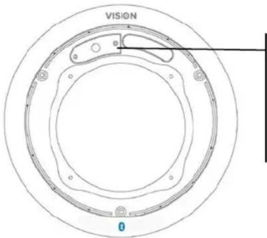
- REMOVE GRILLES Push clamps up. The tip of the screw will push the grille up and off.
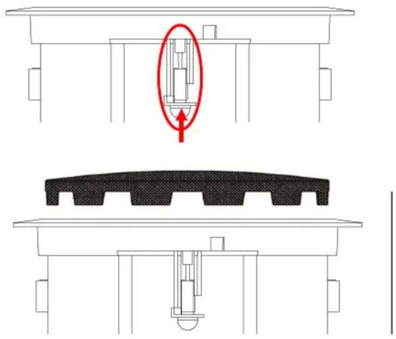
natural_image
Technical diagram showing a mechanical assembly with a highlighted component and cross-sectional views (no text or symbols)- CUT HOLE IN CEILING TILE Diameter 222 mm (8.74")
- FIT LOUDSPEAKERS TO CEILING TILE Fix loudspeaker from the bottom of the ceiling tile and turn clamps out to hold in place.
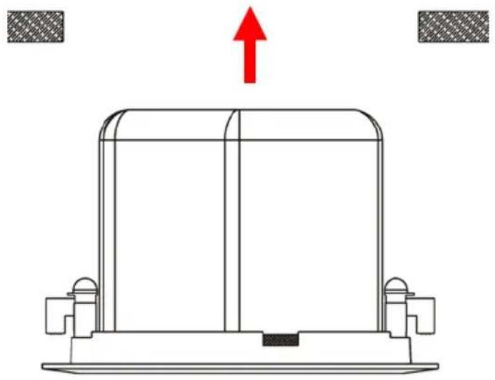
natural_image
Technical line drawing of a mechanical component with a red upward arrow indicating force or direction (no text or symbols)- FIX LOUDSPEAKERS TO CEILING TILE turning clamp screws from the front of loudspeaker. The clamps will turn out and tighten.
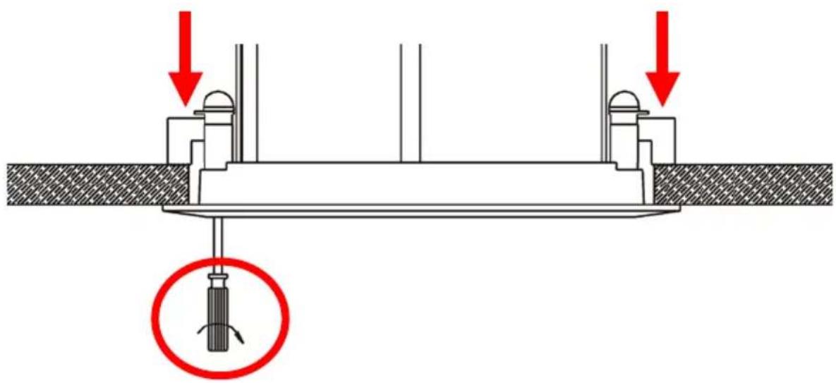
text_image
Technical diagram showing a screwdriver inserted into a structural component with red arrows indicating downward force directions.- CONNECT LOUDSPEAKERS TOGETHER Use the included speaker cable. If cable provided is not long enough use unshielded speaker cable with gauge of 0.75mm or higher.
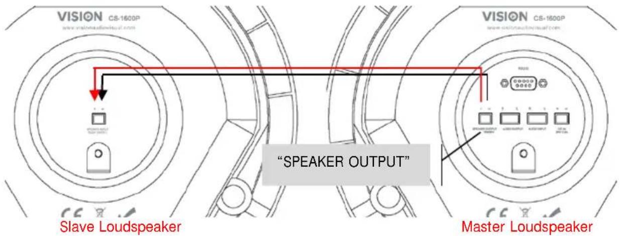
text_image
VISION CS-1600P www.visionaudvisual.com Slave Loudspeaker "SPEAKER OUTPUT" Master Loudspeaker- CONNECT INPUT Plug the phoenix-to-minijack/phono adaptor (shown below) into the input connectors on the rear panel.
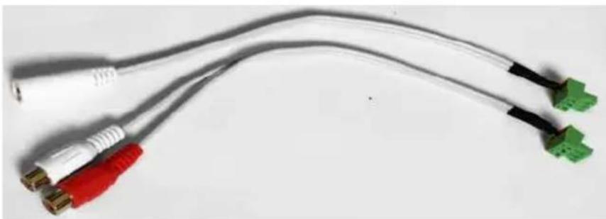
natural_image
Coiled electrical connectors with colored wires (red, white, black) and connectors (green), no visible text or symbolsNote 1: Smartphones, laptops, DVDs etc connect to this input from their headphone or line-level output jacks.
Note 2: If you will use only the Bluetooth input ignore this step.
text_image
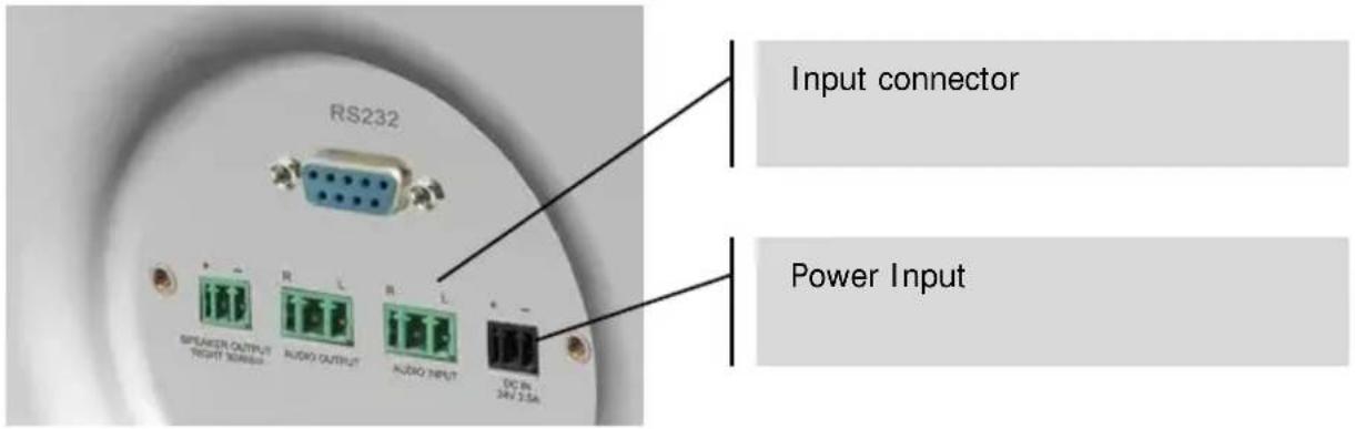
RS232 Input connector Power Input SPEAKER OUTPUT RIGHT NUMBER AUDIO OUTPUT AUDIO INPUT DC IN 24V 3.5A- CONNECT POWER Connect power into rear of master loudspeaker.
- *OPTIONAL* CONNECT MORE SETS OF CS-1600P If using more than one pair of loudspeakers in the room link them together by connecting the Audio output connector to the audio input on the second pair.
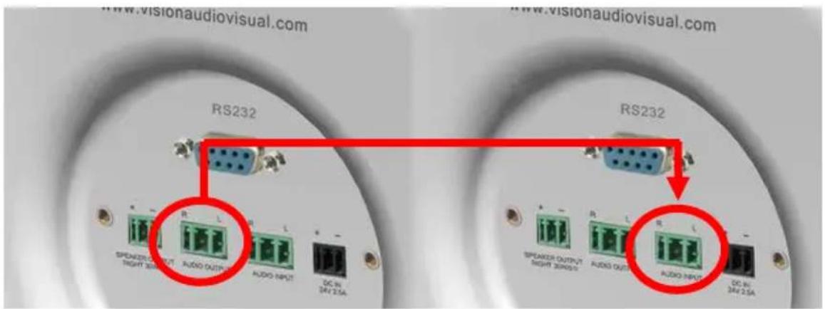
text_image
www.visionaudiovisual.com RS232 RS232 SPEAKER OUTPUT SPEAKER OUTPUT SPEAKER OUTPUT SPEAKER OUTPUT SPEAKER OUTPUT SPEAKER OUTPUT SPEAKER OUTPUT SPEAKER OUTPUT SPEAKER OUTPUT SPEAKER OUTPUT SPEAKER OUTPUT SPEAKER OUTPUT SPEAKER OUTPUT SPEAKER OUTPUT SPEAKER OUTPUT SPEAKER OUTPUT SPEAKER OUTPUT SPEAKER OUTPUT SPEAKER OUTPUT SPEAKER OUTPUT SPEAKER INPUT SPEAKER INPUT SPEAKER INPUT SPEAKER INPUT SPEAKER INPUT SPEAKER INPUT SPEAKER INPUT SPEAKER INPUT SPEAKER INPUT SPEAKER INPUT SPEAKER INPUT SPEAKER INPUT SPEAKER INPUT SPEAKER INPUT SPEAKER INPUT SPEAKER INPUT SPEAKER INPUT SPEAKER INPUT SPEAKER INPUT SPEAKER INPUT SPEAKER OUTPUT SPEAKER OUTPUT SPEAKER OUTPUT SPEAKER OUTPUT SPEAKER OUTPUT SPEAKER OUTPUT SPEAKER OUTPUT SPEAKER OUTPUT SPEAKER OUTPUT SPEAKER OUTPUT SPEAKER OUTPUT SPEAKER OUTPUT SPEAKER OUTPUT SPEAKER OUTPUT SPEAKER OUTPUT SPEAKER OUTPUT SPEAKER OUTPUT1
^st Master Loudspeaker
2
nd Master Loudspeaker
Vision offers Techconnect cable pre-terminated to make this connection:
5m (16.4 feet): TC2 5M3.5MM
10m (32.8 feet): TC2 10M3.5MM
15m (49.2 feet): TC2 15M3.5MM
20m (65.6 feet): TC2 20M3.5MM
STATUS INDICATORS
On the master loudspeaker a solid light indicates that power is on and that an input is selected:
text_image
VISION 0YELLOW: Cabled input selected
BLUE FLASHING: Bluetooth pairing activated (cabled input still selected)
BLUE NOT FLASHING: Bluetooth input selected
REMOTE CONTROL
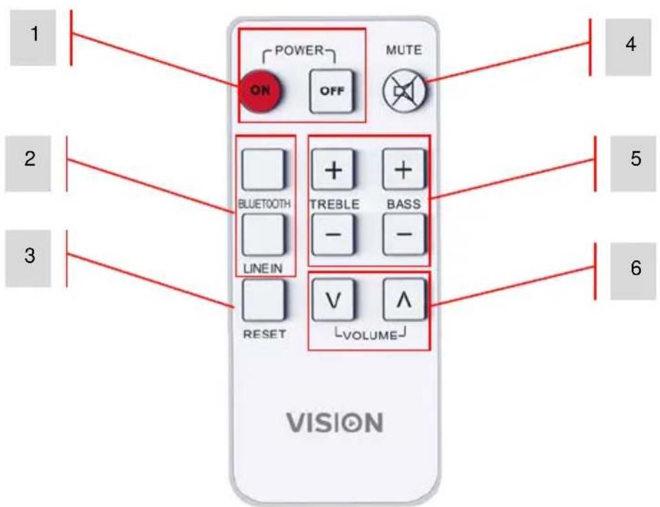
text_image
1 2 3 POWER ON OFF MUTE BLUETOOTH LINE IN + + + TREBLE BASS - - RESET V V VOLUME 4 5 6 VISION- Power On and Off
- Input Selection
- Tone Reset
- Mute
- Tone Control
- Volume
OPERATION
- TURN ON/OFF This product will come on automatically when power is turned on. Or use the remote control to turn on. The product will always resume the last input and volume level.
NOTE: The IR receiver is built into the front of the master loudspeaker. The master loudspeaker has lights on the front panel, the slave does not.
- SELECT BLUETOOTH INPUT
a. Turn loudspeakers ON or select Bluetooth on remote control.
The blue light starts to flash to show it is in pairing mode. At this point the cabled input is still active input.
b. On your device turn Bluetooth on.
c. Connect to "VISION SPEAKERS". The yellow light will turn off, and the blue light will be on continuously to indicate the Bluetooth source is now selected.
NOTE 1: If you have connected before it will automatically connect when you turn Bluetooth on.
- AUTO-STANDBY If the amplifier senses no input it will automatically go into standby mode.
As soon as you press play on your source device it will automatically switch on again.
If loudspeakers were put into standby manually they will not wake up automatically.
RS-232 CODES
This product can be controlled with the included remote control or by a professional AV control system using RS-232 codes.
Table 1: Control Codes
| HEX Codes | On Remote | Function |
| 65 11 11 | ON | Bring out of standby |
| 65 15 15 OFF | Put into standby | |
| 65 05 05 MUTE | Mute on/off (Standby activates after 30 minutes of mute) | |
| 65 01 01 | BLUETOOTH | Input select “Bluetooth” |
| 65 09 09 | LINE IN | Input select “Line In” |
| 65 08 08 | TREBLE+ | Increase treble gain by +1dB |
| 65 0D 0D | TREBLE- | Decrease treble gain by -1dB |
| 65 0C 0C | BASS+ | Increase bass gain by +1dB |
| 65 12 12 | BASS- | Decrease bass gain by -1Db |
| 65 00 00 | RESET | Reset tone |
| 65 07 07 | VOL+ | volume + (also cancels mute if active) |
| 65 0B 0B | VOL- | volume - (also cancels mute if active) |
| 65 A0 A0 | Volume Step 0 | |
| 65 A1 A1 | Volume Step 1 | |
| 65 A2 A2 | Volume Step 2 | |
| 65 A3 A3 | Volume Step 3 | |
| 65 A4 A4 | Volume Step 4 | |
| 65 A5 A5 | Volume Step 5 | |
| 65 A6 A6 | Volume Step 6 | |
| 65 A7 A7 | Volume Step 7 | |
| 65 A8 A8 | Volume Step 8 | |
| 65 A9 A9 | Volume Step 9 | |
| 65 AA AA | Volume Step 10 | |
| 65 AB AB | Volume Step 11 | |
| 65 AC AC | Volume Step 12 | |
| 65 AD AD | Volume Step 13 | |
| 65 AE AE | Volume Step 14 | |
| 65 AF AF | Volume Step 15 | |
| 65 B0 B0 | Volume Step 16 | |
| 65 B2 B2 | Volume Step 18 | |
| 65 B3 B3 | Volume Step 19 | |
| 65 B4 B4 | Volume Step 20 | |
| 65 B5 B5 | Volume Step 21 | |
| 65 B6 B6 | Volume Step 22 | |
| 65 B7 B7 | Volume Step 23 | |
| 65 B8 B8 | Volume Step 24 | |
| 65 B9 B9 | Volume Step 25 | |
| 65 BA BA | Volume Step 26 | |
| 65 BB BB | Volume Step 27 | |
| 65 BC BC | Volume Step 28 | |
| B5 B1 B1 | Volume Step 17 | |
A command is structured of 65 then the command twice
e.g. turn on: send 65 then send 11 twice.
Each part of the code is preceded by "0x" so the longhand is 0x65 0x11 0x11
Table 2: Return Codes
To request status send 65 65 65
| Function Name | Function | Range | Remark | |||
| working | off | standby | ||||
| STANDBY | 0 | 1 | 1 | 0 | 0 | |
| MUTE | Mute status | 0 | 1 | 0 | 1 | 1 |
| BD3490FV_SELECT | Input select | 0 | 2 | |||
| BD3490FV_GAIN_GET | Get volume | 1 | 28(1C) | 1~28, volume has 28 steps | ||
| BD3490FV_B_GAIN_GET | Get bass gain | 1 | 15(0F) | Bass gain has 15 steps | ||
| BD3490FV_T_GAIN_GET | Get treble gain | 1 | 15(0F) | Treble gain has 15 steps | ||
| BT_BIT Bluetooth status | 0 1 | Connected = 1Disconnected = 0 | ||||
Baud rate: 9600K
Stop Bit: 1
Delivery interval >80ms
No check digit
NOTE: Auto-Standby activates after 30 minutes of mute or no operation. Any adjustment turns standby off.
TROUBLESHOOTING
If your system is not operating properly, please refer to the following information.
| Problem | Correction |
| No power light | Check power source and power input cable Check fuse in power cable plug Check battery in remote |
| Power light on but no sound | Turn the volume up with remote. Make sure the output volume on your test device is at full and that it works through the built-in device loudspeakers. |
| Hum or noise | Check that all input cables shielded properly. Poor quality cable with uneven shielding introduces noise. Long cables are particularly susceptible to picking up induced noise. Adding Ferrite cores may help to reduce this. Make sure all source devices are connected to the same power source. If disconnecting a laptop from power solves the problem then this is definitely the cause of the problem. |
| Slave loudspeaker not working | Check speaker cable to ensure there a proper connection at both ends. If possible test with another slave loudspeaker. |
| Slave loudspeaker is quieter than master loudspeaker | This is typically caused by the use of incorrect cable between the master and slave loudspeakers. It is too thin, or shielded. Replace cable immediately. |
| Device not connecting to Bluetooth | Bluetooth driver implementation on Windows PCs is not consistent. You may need to download drivers from your computer manufacturer's website, and even then you may not be able to make it work. |
SPECIFICATIONS
PRODUCT DIMENSIONS: 260 x 180 mm / 10.2" x 7.1" (diameter x height for each speaker)
CUTOUT SIZE: 222mm / 8.74"
PRODUCT WEIGHT: 4.9 kg / 10.8 lb (per pair)
CONSTRUCTION MATERIAL: Plastic (ABS) + Sheet metal back can
COLOUR: White
TECHNICAL DETAILS:
Amplifier Output: 2 x 30 watts (RMS)
Woofer: 4"
Tweeter: 1.5" Silk
Output Impedance: 8 ohms
Sensitivity: 89 dB (1w/1m)
Frequency response: 80 Hz-20 kHz
Power Consumption: ≤ 70 w
MASTER LOUDSPEAKER INPUTS:
Input 1: Phoenix connector
Serial Connector: 9-pin D-sub connector
Speaker Output: Phoenix connector
Speaker Output (on master): Phoenix connector
Speaker input (on slave): Phoenix connector
POWER SUPPLY: 100-240v 50/60Hz AC External Power Supply - 24 volt / 2.5 amp. Laptop-style
transformer. Includes 4 x 0.5m figure-8 power cables: UK/EU/US/AU. DC tail length: 4m.
Transformer dimensions: 120 x 56 x 36mm
COMPLIANCE: RoHS, WEEE, CE/EMC, CE/LVD, FCC
ACCESSORI ES:
1 x Speaker Cable 5 m (16.4') long
1 x Remote Control (Battery included: CR2025 3V Li-Mn)
1 x Female Minijack to Phoenix connector cable
1 x Female 2-Phono to Phoenix connector cable
Frequency Response Graph: (dBSPL vs Frequency)

line
| Frequency | dUSPL | | --------- | ----- | | 20 Hz | 55 | | 50 | 65 | | 100 | 70 | | 200 | 85 | | 500 | 88 | | 1K | 90 | | 2K | 92 | | 5K | 90 | | 10K | 78 | | 20K | 80 |WARRANTY
This product comes with a 2-year return to base warranty, effective from the date of purchase. This warranty applies only to the original purchaser and is not transferable. For the avoidance of doubt, this will be taken from the information held by the appointed national distributor at the point of sale. If the product is DOA (dead on arrival), you have 21 days from purchase date to notify the national distributor via your AV reseller. The liability of the manufacturer and its appointed service company is limited to the cost of repair and/or replacement of the faulty unit under warranty, except for death or injury (EU85/374/EEC). This warranty protects you against the following:
- Failure of any components, including the power supply.
- Damage when the product is first removed from its packaging if reported within 24 hours of purchase.
If you find you do have a problem with this product, you should contact the AV reseller you purchased this product from. The original purchaser is responsible for shipment of the product to the manufacturer's appointed service centre for repair.
We will endeavour to return repaired units within 5 working days, however this may not always be possible, in which case it will be returned as soon as practicably possible. In line with our WEEE commitments, the manufacturer endeavours to replace the faulty parts of the product rather than replacing the whole unit. This warranty does not protect this product against faults caused by abuse, misuse, incorrect installation, unstable or faulty power input, which might be caused by ignoring the guidelines set out in this manual.
LEGAL DISCLAIMER: Because we are committed to improving our products, the details above may change without prior warning. This User Manual is published without warranty and any improvements or changes to the User Manual necessitated by typographical errors, inaccuracies of current information, or improvements to programs and/or equipment, may be made at any time and without notice. Such changes will be incorporated into new editions of the User Manual.