
FU9001 - Secure Access Control System ABUS - Free user manual and instructions
Find the device manual for free FU9001 ABUS in PDF.

| Product Type | Secure Access Control System |
| Brand | ABUS |
| Model | FU9001 |
| Dimensions (H x W x D) | 120 x 80 x 30 mm |
| Weight | 250 g |
| Power Supply | 12V DC, 500 mA |
| Backup Battery | 9V alkaline (not included) |
| Authentication Methods | Keypad (PIN), RFID card, mechanical key override |
| Number of Users | Up to 100 PIN codes, 100 RFID cards |
| Operating Temperature | -20°C to +60°C |
| Ingress Protection | IP54 (splash-proof) |
| Material | Zinc alloy housing, stainless steel strike |
| Installation | Surface mount on door, standard mortise lock preparation |
| Maintenance | Clean with a soft dry cloth; avoid chemical cleaners |
| Safety Features | Tamper alarm, auto-lock after wrong attempts, emergency key release |
| Spare Parts Available | Key override cylinders, RFID cards, mounting screws |
| Repairability | Field replaceable battery and keypad module; professional service recommended for electronics |
| Standard Compliance | CE, EN 16864 (electronic locks) |
Frequently Asked Questions - FU9001 ABUS
User questions about FU9001 ABUS
0 question about this device. Answer the ones you know or ask your own.
Ask a new question about this device
Download the instructions for your Secure Access Control System in PDF format for free! Find your manual FU9001 - ABUS and take your electronic device back in hand. On this page are published all the documents necessary for the use of your device. FU9001 by ABUS.
USER MANUAL FU9001 ABUS
ABUS WIRELESS ALARM SYSTEM
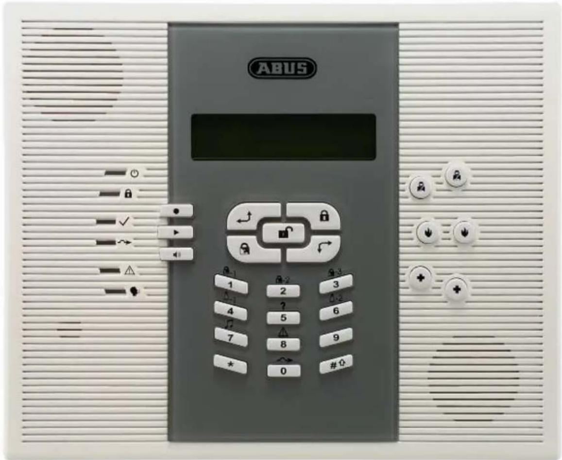
INSTALLATION INSTRUCTION
These installation instructions are an important product accessory. They contain important installation and operation information. Bear this in mind if you pass the product on to others.
Store these installation instructions in a safe place for future reference.
For a list of contents with page numbers, see page 3.
For brief instructions of starting up the ABUS wireless alarm package, see page 10-91.
ABUS WIRELESS ALARM SYSTEM
These installation instructions are published by ABUS Security-Center GmbH & Co. KG, Linker Kreuthweg 5, D-86444 Affing/Mühlhausen.
All rights including translation reserved. Reproductions of all kinds – e.g. photocopy, microfilm, or storage in computer systems – require the express written permission of the publisher.
Reprinting prohibited, even in part.
These operating and installation instructions correspond to the state of the art at the time of printing. We reserve the right to make changes to technology and equipment. Liability for printing errors and technical changes excluded.
© Copyright 2010 by ABUS Security-Center GmbH & Co. KG.
Contents
Contents....1-3
Chapter 1 Usage in accordance with regulations....1-6
Chapter 2 Safety information 2-6
Chapter 3 Introduction to the ABUS wireless alarm system....3-7
3.1 Scope of delivery 3-7
3.2 What is the ABUS wireless alarm system? 3-8
3.3 What are the functions of the ABUS wireless alarm system? 3-8
3.4 What are the technical specifications of the ABUS wireless alarm system? 3-8
3.5 How can the ABUS wireless alarm system be extended? 3-10
3.6 CE manufacturer's declaration 3-11
Chapter 4 Initial considerations....4-12
4.1 What kinds of security are there? 4-13
4.2 What wireless detectors do I need? 4-14
4.3 Where do I install the ABUS wireless alarm system? 4-14
4.4 What is the best installation sequence? 4-14
Chapter 5 Installing the ABUS wireless alarm system ....5-15
5.1 What is what inside the ABUS wireless alarm system? 5-15
5.2 How do I install the ABUS wireless alarm system? 5-16
5.2.1 Preparing the base plate....5-16
5.2.2 Assembling the base plate....5-16
5.2.3 Fixing the faceplate....5-17
5.3 How do I install the power and telephone connections? 5-17
5.4 How do I adjust the contrast of the LCD display? 5-17
5.5 How do I connect the other contacts in the ABUS wireless alarm system? 5-18
5.5.1 Connecting a wired sounder 5-18
5.5.2 Sounder tamper 5-18
5.5.3 Controllable relay and transistor outputs....5-18
5.5.4 Connecting a device ground 5-19
5.5.5 Connecting a wired zone 5-19
5.5.6 Connecting an external consumer 5-19
5.6 How are the standby batteries used? 5-20
5.7 What are the effects of the different jumper settings? 5-21
Chapter 6 Programming the ABUS wireless alarm system....6-22
Chapter 7 Settings in installer menu 7-22
7.1 Introduction to installer menu 7-22
7.2 System 7-23
7.2.1 Timers 7-23
7.2.2 System Control 7-25
7.2.3 3 Receiver....7-31
7.2.4 1 4 Set Clock....7-32
7.2.5 5 Labels 7-33
7.2.6 6 Tamper Sound 7-35
7.2.7 System Default Jumper....7-36
7.2.8 8 Service Information....7-36
7.2.9 Version....7-36
7.3 Zones 7-37
7.3.1 Allocation 7-37
7.3.2 2 Parameters 7-38
7.3.3 Zone Testing 7-48
7.3.4 4 Editing....7-49
7.3.5 5 Cross Zone 7-51
7.4 Outputs....7-52
7.4.1 1 Define 7-52
7.4.2 Output A....7-57
7.4.3 3 Output B....7-57
7.5 Codes 7-58
7.5.1 4 1 Authority 7-58
7.5.2 Partition....7-60
7.5.3 Grand Master 7-60
7.5.4 4 Installer 7-61
7.5.5 5 Sub-Installer....7-61
7.5.6 Code Length 7-62
7.6 Dialer 7-63
7.6.1 4 U/D telephone number....7-63
7.6.2 5 U/D Access and ID 7-63
7.6.3 Controls 7-64
7.6.4 7 Parameters....7-66
7.6.5 9 Follow Me (FM)....7-69
7.7 Key-fobs 7-71
7.7.1 Allocation 7-71
7.7.2 2 Parameters 7-72
7.7.3 3 Communication Test....7-73
7.8 Keypads 7-74
7.8.1 Allocation 7-74
7.8.2 Communication Test....7-75
7.9 Siren 7-75
7.9.1 Allocation 7-76
7.9.2 2 Parameter....7-77
7.9.3 3 Communication test....7-78
7.9.4 4 Siren Receiver Calibration....7-78
7.9.5 5 Tamper Mute 7-79
7.10 Exit Programming 7-80
Chapter 8 Programming within the user programming menu....8-81
8.1 Programming voice messages 8-81
8.1.1 1 Message structure 8-82
8.1.2 2 Voice message labels....8-83
8.1.3 3 Test Message 8-87
8.1.4 4 Local Announcement Messages....8-88
8.2 Walk test....8-89
Chapter 9 Accessories for your ABUS wireless alarm system....9-90
Chapter 10 Brief guide .... 10-91
10.1 Hardware installation....10-91
10.1.1 ABUS wireless alarm system....10-91
10.1.2 Wireless opening detector 10-91
10.1.3 Wireless motion detector 10-91
10.1.4 Wireless smoke detector....10-91
10.2 Training the detectors for the ABUS wireless alarm system.... 10-92
10.2.1 Installer menu of the ABUS wireless alarm system....10-92
10.2.2 Allocate detectors 10-92
10.2.3 Programming zones....10-93
10.2.4 Allocate key-fobs....10-93
10.2.5 Programming the key fob....10-93
10.3 Enabling voice text transmission by telephone....10-93
10.4 Exiting the installer menu 10-94
10.5 Programming date and time 10-94
10.6 Programming the FM (follow me) number 10-94
10.7 Triggering a test alarm....10-95
10.8 Changing the Grand Master PIN 10-95
Chapter 11 Example of an installation plan....11-96
Appendix A: Event Log Messages 11-98
Chapter 1 Usage in accordance with regulations
The ABUS wireless alarm system is used for protecting flats and homes and small to medium business objects. If the wireless alarm system and its accessories are installed properly, it alerts you in the case of intrusion, warns you about fires, and calls for help in the event of an emergency.
The wireless alarm system and its accessories are designed for protected interior spaces (environment class 1) and must be used there only. Make sure that the specified environment conditions are met. If the specified environment conditions are not met, the proper operation of the wireless alarm system and its accessories cannot be guaranteed. Besides false alarms, irreversible damage can be done to components if the environment conditions are not met, even for a short period, leading to a complete failure in individual components or the entire system.
The external wireless sounder and the wireless remote controls are exceptions to the environment class described above. Please note the corresponding environment conditions for these products.
The wireless alarm system cannot prevent burglary, hold-ups, fire or vandalism. When properly installed, it is used for local information and the forwarding of this information by telephone using voice messages.
The wireless alarm system works on a frequency band in the 868MHz frequency range specially protected for alarm systems. This prevents other consumer products such as baby phones disturbing the operation of the wireless alarm system. However, it cannot be excluded that radio transmission is temporarily or permanently interfered with by defective components of other electrical or electronic products such as ventilator fans, antenna boosters, etc. Furthermore, radio transmission can also be interfered with consciously and wantonly from outside. However, the wireless alarm system is capable of detecting and reporting such disturbances when normal radio traffic is no longer ensured.
All accessories of the wireless alarm system work with batteries that have only a limited service life. The system monitors the battery condition of the accessories and reports in advance when the accessory batteries have to be replaced. You should then replace the batteries as soon as possible. The accessories work only as long as there is sufficient power available for proper operation. If this is no longer the case, they automatically go out of operation. A detector in this state can no longer fulfil its function.
The wireless alarm system is supplied with energy from the general power supply network and has standby rechargeable batteries for emergencies. The standby batteries maintain full operation of your wireless alarm system for several hours. However, the system is not designed for permanent battery operation. If there is a longer power failure, the energy of the standby batteries will be used up. The alarm system works only as long as there is sufficient power available for proper operation. If this is no longer the case, it automatically goes out of operation. The functions described are then no longer available.
All information and programming settings are saved in a long-term memory (EEPROM) and are available again following a complete failure of the system (even after several months). When you restart the system, all you have to do is correct the date and time.
Chapter 2 Safety information
For damage caused by non-compliance with these installation instructions, no guarantee claims are possible. No liability can be accepted for resulting damage.
In the case of material or personal damage caused by improper operation or non-compliance with the security notes, no liability or guarantee claim can be accepted.
For security and authorisation reasons (CE), the unauthorised alteration and/or changing of the alarm system and its components is not permitted.
Only a regulation network power socket (230 Volt / 50 Hz or 110Volt / 60Hz) of the public supply network can be used as a power source.
Make sure the alarm system is correctly put into service. Follow these installation instructions carefully to ensure this.
The equipment should be installed and started up by a correspondingly qualified person to ensure the safe operation of this product. When installing the product, make sure the supply power line is not restricted or damaged by sharp edges.
Never install the alarm system near combustible or easily flammable materials such as curtains. Do not expose the alarm system to high temperatures, strong vibrations or dampness.
Equipment operated with mains electricity should be kept out of the reach of children. For this reason, be particularly careful when children are present.
In commercial institutions, ensure compliance with accident prevention regulations issued by professional bodies responsible for electrical equipment.
Pay special attention to passages marked with an exclamation mark in these instructions. These identify particularly important explanations or safety hints that must be observed.
Chapter 3 Introduction to the ABUS wireless alarm system
Congratulations – you made the right choice! The ABUS wireless alarm system offers you professional technology and first-class quality of the specialist for domestic security, packed in a modern, attractive design, and gives you a great feeling of safety and security day after day.
First please check the contents of this package for completeness according to the following specifications and contact the vendor immediately in the event of any deviations.
FOR BRIEF INSTRUCTIONS OF STARTING UP THE ABUS WIRELESS ALARM PACKAGE, SEE PAGE 11-88.
Replace defective or missing parts of this equipment with original parts only. You can obtain these from your local dealer.
This chapter answers the following questions:
• What is the ABUS wireless alarm system?
• What are the functions of the ABUS wireless alarm system?
• What are the technical specifications of the ABUS wireless alarm system?
• How can the ABUS wireless alarm system be extended?
For further advice on using, maintaining and servicing your ABUS wireless alarm system, refer to the accompanying user instructions.
If your questions are not answered completely in this or the following chapters, and the user instructions or the installation DVD offer no explanation, please contact your specialist dealer, who has received detailed training and will be happy to advise you.
3.1 Scope of delivery
The ABUS wireless alarm package consists of the following components:
Installation and programming instructions 1x
User guide
DVD with installation video 1x
Brief instructions for telephone commands 1x


Power adapter (according to techn. specifications) 1x
Rechargeable batteries (according to techn. specifications) 6x
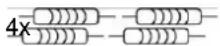
2.2kOhm resistors
Screws (4,2 x 32 4x, 2,9 x 13 1x, 2,9 x 6,5 1x)
Wireless magnet contact, white 1x
Wireless remote control
Wireless motion sensor


1x
1x
3.2 What is the ABUS wireless alarm system?
The ABUS wireless alarm system is an alarm system specially designed and developed for house owners and the owners of small to medium commercial objects. The wireless alarm system ensures 24-hour security with the help of the wireless sensors and detectors installed in your property. Depending on your particular version, the ABUS wireless alarm system triggers burglar alarms, warns you about fire, and calls for help in the event of household emergencies. The ABUS wireless alarm system also has intelligent control functions that can be integrated in modern house management systems, such as EIB. These can also be remote-operated from a distance.
3.3 What are the functions of the ABUS wireless alarm system?
The ABUS wireless alarm system provides reliable surveillance. In the event of an alarm triggered by wireless detectors (e.g.: (smoke, magnet, motion sensor), wireless emergency button (e.g.: panic emergency call), or by system faults (e.g.: power failure), the ABUS wireless alarm system automatically calls previously programmed telephone numbers and activates local sounders, depending on the alarm.
The ABUS wireless alarm system informs and plays previously recorded announcements when called. It then transmits the cause of the alarm (e.g.: fire, emergency) or the system messages (e.g.: power failure, battery fault).
The ABUS wireless alarm system keeps you in touch. You can use the integrated microphone and loudspeaker to speak by telephone into the room and also to listen in to what is happening in it. For a control call, you just dial into the ABUS wireless alarm system.
The ABUS wireless alarm system gives you security since if anything happens, it calls until you or a person defined by you answers the call. The ABUS wireless alarm system can react and act remotely. You can activate and deactivate the ABUS wireless alarm system with a telephone call. You can also activate the control outputs and program the alarm numbers to any selected destination.
The ABUS wireless alarm system is simple to program and operate. The logically designed installation procedure is menu-guided like the user instructions. The user also receives the most important system events as voice output.
3.4 What are the technical specifications of the ABUS wireless alarm system?
Operating voltage: Primary: 230V AC / 50Hz power adapter
Secondary: 9V AC / 50Hz
Power consumption: Primary: 113mA max.
Secondary: 140mA min. / 2000mA max.
Emergency power supply: 6 x 1.2V AA NiCd rechargeable batteries (min. 800mAh)
o r
6 x 1.5V DC AA alkaline batteries
Control outputs: 2 x relays, max. 3A at 24V DC
2 x transistors, max. 70mA
Voltage output: 1 x 9V DC max. 200mA (constant)
1 x 9V DC max. 500mA (controllable)
Alarm sounder: 1 x internal 90dBA at 1m
Ambient operating temperature: 0°C to +55°C max. air humidity 90% non-condensing
Case material: ABS
Dimensions: 240 x 190 x 48mm (LxWxH)
Weight: 970g (including batteries)
Dialling mode: DTMF / CTMF (tone dialling)
Radio immunity: acc. to EN 50130-4
Radio frequency: 868.65 MHz AM narrow band
Further licences such as CE, radio and telephone operation are in the manufacturer's possession and can be requested if necessary. Please contact your dealer about this.
The following graphic gives you an overview of further function properties of your ABUS wireless alarm system:
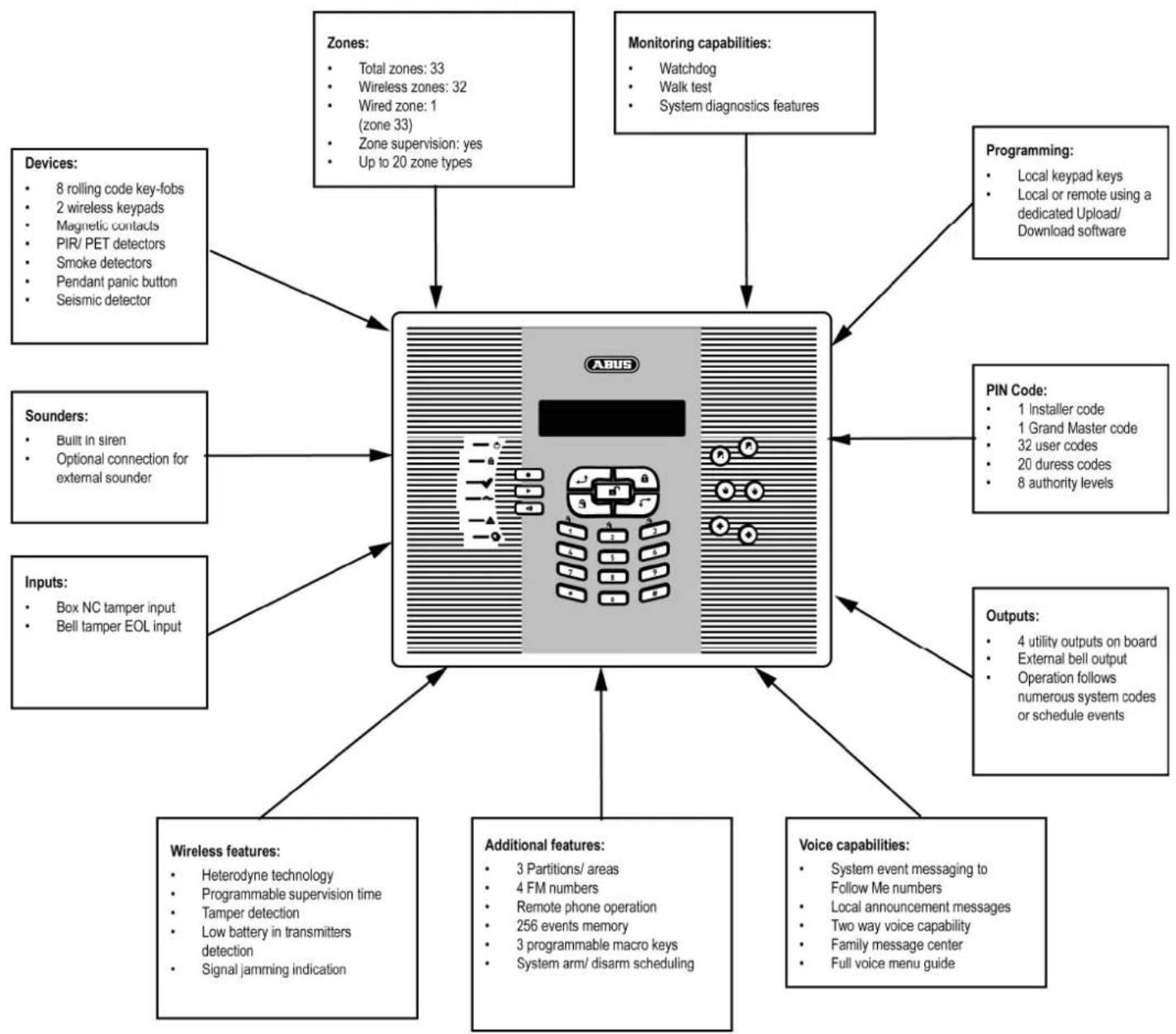
flowchart
graph TD
    A["ABUS Device"] --> B["Zones: Total zones: 33, Wireless zones: 32, Wired zone: 1 (zone 33), Zone supervision: yes, Up to 20 zone types"]
    A --> C["Monitoring capabilities: Watchdog, Walk test, System diagnostics features"]
    A --> D["Programming: Local keypad keys, Local or remote using a dedicated Upload/Download software"]
    A --> E["PIN Code: 1 Installer code, 1 Grand Master code, 32 user codes, 20 duress codes, 8 authority levels"]
    A --> F["Outputs: 4 utility outputs on board, External bell output, Operation follows numerous system codes or schedule events"]
    A --> G["Voice capabilities: System event messaging to Follow Me numbers, Local announcement messages, Two way voice capability, Family message center, Full voice menu guide"]
    A --> H["Additional features: 3 Partitions/ areas, 4 FM numbers, Remote phone operation, 256 events memory, 3 programmable macro keys, System arm/disarm scheduling"]
    A --> I["Wireless features: Heterodyne technology, Programmable supervision time, Tamper detection, Low battery in transmitters detection, Signal jamming indication"]
    A --> J["Inputs: Box NC tamper input, Bell tamper EOL input"]
    A --> K["Sounders: Built in siren, Optional connection for external sounder"]
    A --> L["Devices: 8 rolling code key-fobs, 2 wireless keypads, Magnetic contacts, PIR/PET detectors, Smoke detectors, Pendant panic button, Seismic detector"]
3.5 How can the ABUS wireless alarm system be extended?
The ABUS wireless alarm system is a modular, extendable security system. The following graphic shows how it can be extended:
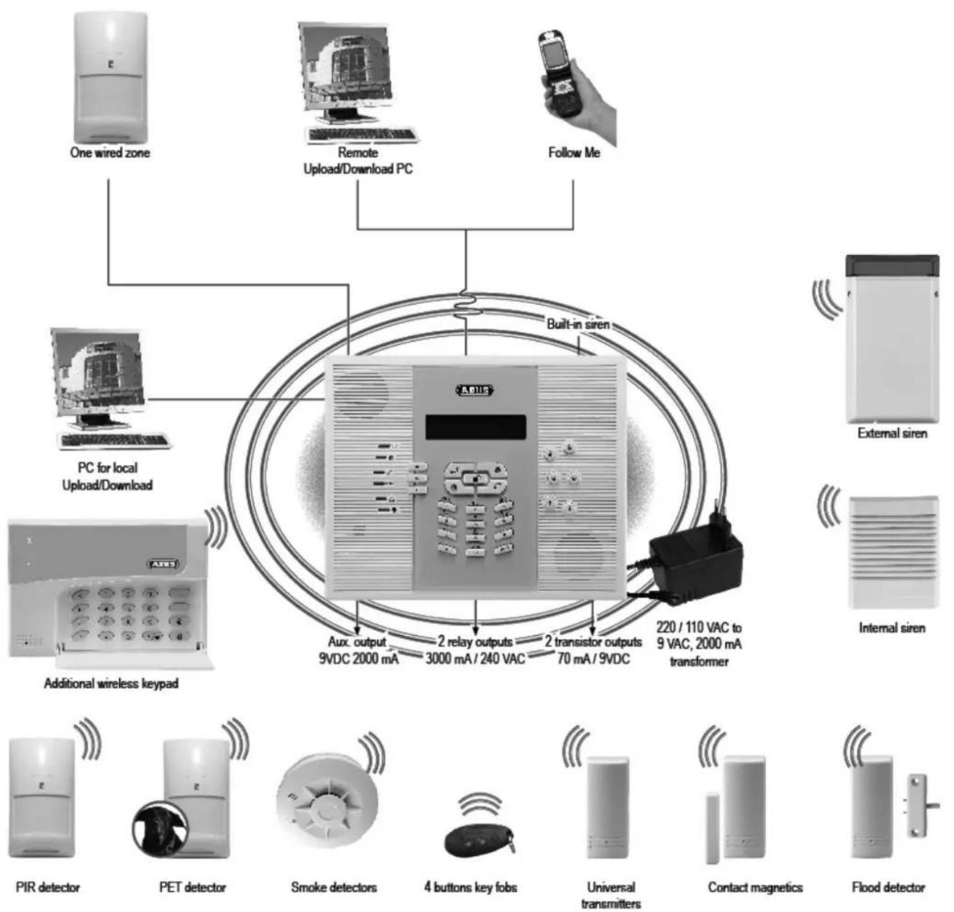

security center
EG - KONFORMITÄTSERKLÄRUNG EC - DECLARATION OF CONFIRMITY

complies with the requirements and the provisions of the
- Directive 1999/5/EC of the European Parliament and of the council of 9 march 1999 on Radio equipment and Telecommunications Terminal Equipment and the mutual recognition of their conformity and Annex III (Conformity Assessment procedure referred to in article 10 (4)).
And furthermore declares that the following parts of standards and documents have been applied:
EN60950-1 :2001, EN301 489-3 v.1.4.1 :2002, EN50130-4 :95+A1+A2, EN300220-3 :00, EN300220-1 :00, TBR21 :98, ETSI EG 201121
Place and date of issue
Name, function and signature of authorised person

Chapter 4 Initial considerations
Before starting to install your new ABUS wireless alarm system, please take the time to consider the following. You will find helpful tips for planning your system on the accompanying installation DVD. If you cannot find answers to all your questions, please contact your specialist dealer, who will be pleased to help you. Remember: only a correctly planned and installed alarm system provides maximum security.
This chapter answers the following questions:
• What kinds of security are there?
• What wireless detectors do I need?
• Where do I install the ABUS wireless alarm system?
• What is the best installation sequence?
The following graphic shows where to install the different wireless detectors.

4.1 What kinds of security are there?
In general, there are three different ways of securing an object:
External perimeter surveillance, in which primarily the endangered areas such as the entrance door, terrace door and cellar door as well as ground-floor windows are protected by wireless magnet contacts and wireless glass breakage detectors. The next step is to make sure that all other access areas are protected. Unprotected access areas are a security risk since there is no detection using wireless motion sensors inside the object.
This type of surveillance is particularly recommended for pet owners of dogs, cats, etc. since these animals can cause false alarms on interior detectors (motion sensors).
Internal surveillance (surveillance of certain areas and/or traps), where you monitor only the interior of your object. There is no surveillance of the external perimeter. Protection using wireless motion sensors begins with the areas most likely to be crossed by burglars such as entrances, halls, and living rooms. In the next stage, every room can be protected individually.
Internal surveillance is the cheapest type of surveillance, and the burglar may be detected quite late, when he or she is already inside the object.
The combination of these two protection methods, which closes security gaps in the “outer skin” surveillance through the use of interior detectors (wireless motion sensors). The burglar is detected either when entering the object or when moving within the object.
The combination of these two protection types offers you maximum security.
We recommend the use of wireless smoke detectors since every electrical device in your house represents a potential fire hazard. First of all, the halls and stairways should be protected, with at least one detector per floor. Equally important are areas such as children's playrooms, bedrooms and living rooms, where each room should have its own detector.
Smoke detectors save lives!
You operate the wireless alarm system either with the remote control provided, a wireless control panel, or a wireless key switch. The system can be controlled directly from the ABUS wireless alarm system. The system is also programmed on this keypad. Other features are remote-controlled activation and programming by telephone or remote PC, which will be explained later in these instructions. For more information of operating the wireless alarm system, see the operating instructions and the installation DVD. If in doubt, please contact your specialist dealer.
4.2 What wireless detectors do I need?
The type and number of wireless detectors needed depends partly on the type of protection and partly on the level of security you want to achieve. You should therefore plan your wireless sensors as follows:
- Consider how an intruder can get into your object. It will help if you draw up a plan of your object, or take a walk around, inside and outside the object. Try to imagine what you would do to get into the object. Don't forget to include any aids that may be available. Direct access via the house door or terrace door is not necessarily the fastest. For example, if a ladder is available, a balcony door or an upstairs window will represent a risk.
- If your object already has good mechanical protection systems such as window locks or extra door locks, these will prevent most burglars from getting into the object.
- Burglaries should always be fast, quiet and inconspicuous. Accesses at hidden areas of your object, such as cellar doors or rear windows, are therefore particularly at risk.
- Plan to install at least one smoke detector in your system – in the bedroom – or even better, three smoke detectors – in the bedroom, in the hall, (escape route) and in the living room (large amount of electrical equipment). Smoke detectors in the kitchen or bathroom are unsuitable because of the natural steam and smoke situation there.
- With the help of the requirements listed above and the tips on the installation DVD, make a list of wireless detectors required and divide them into three categories: Absolutely necessary (high hazard risk), important (medium hazard risk) and less important (low hazard risk, other security messages have already been taken, difficult to reach/overcome).
- Buy all the wireless detectors that are absolutely necessary. Since the system is modular, the wireless detectors of the other categories can also be installed later.
- When operating the system, note that you activate and deactivate the system several times a day. The components should therefore be placed where they are as easy as possible to operate and they do not restrict you in your normal day-to-day life.
If you have questions about protecting your property, consult your specialist dealer. To help you in the planning, make a plan or sketch of your object.
The ABUS wireless alarm system and its components are designed and developed in such a way that they immediately detect and report possible assaults from outside and tamper attempts. Better safe than sorry!
4.3 Where do I install the ABUS wireless alarm system?
The ABUS wireless alarm system should be installed in your house near an analogue telephone connector and a 230V power socket – ideally near the centre of the object to ensure good communication with the detectors. You should not install it directly in the entrance area near the entrance door, where it can easily be tampered with. Use a wireless operating panel here.
Note that the ABUS wireless alarm system must be installed at a minimum distance of 1m to ceilings and floors to guarantee good radio communication. Furthermore, do not install the ABUS wireless alarm system in a cupboard or drawer since the furniture materials would weaken radio reception and you would not hear the voice messages of the system.
On the rear of the equipment there are several openings to enable it to be hung on wall screws. Using the fixing materials provided and a power screwdriver, you can quickly fix the system to the wall. It should be fixed on a flat wall so firmly that the tamper contact on the rear is completely pressed down. If this is not possible, deactivate this contact.
Make sure that the maximum distance between wireless detectors and the ABUS wireless alarm system does not exceed 30m in buildings. Note that building materials and other electrical equipment can restrict the radio transmission range. Look out for strongly reinforced ferro-concrete floors and ceilings (e.g., on the ground floor) or electric under-floor heating systems (Faraday cage).
4.4 What is the best installation sequence?
Install and program your ABUS wireless alarm system in the order described below. The instructions will guide you step by step through the installation. Programming closes with a test alarm leading to a successful alarm triggering on the system (so long as no communication faults exist).
-
Creating an installation plan
-
Connecting and installing the ABUS wireless alarm system.
-
Putting into operation
-
Installer menu and reception check
-
Installing wireless detectors and communication test
-
Programming detector zones
-
Programming alarm reactions
-
Programming announcements and alarm numbers
-
Final settings
-
Activating the system and test alarm
Chapter 5 Installing the ABUS wireless alarm system
Make a sketch of the object or use the architect's plans. Enter the absolutely necessary wireless detectors defined according to chapter 3. Install the detectors in groups. For example: first magnetic contacts, then motion sensors, then smoke detectors. Or divide your object into areas. For example: living room, kitchen,... or ground floor, cellar,...
Name or number the detectors. For a specimen installation plan, see the end of these instructions. You will need the installation plan again and again in the course of your activities.
This chapter answers the following questions:
• What is what inside the ABUS wireless alarm system?
• How do I install the ABUS wireless alarm system?
• How do I install the power and telephone connections?
• How do I adjust the contrast of the LCD display?
• How do I connect the other contacts in the ABUS wireless alarm system?
• How are the standby batteries used?
• What are the effects of the different jumper settings?
5.1 What is what inside the ABUS wireless alarm system?
The following graphic shows the inner structure of the ABUS wireless alarm system.
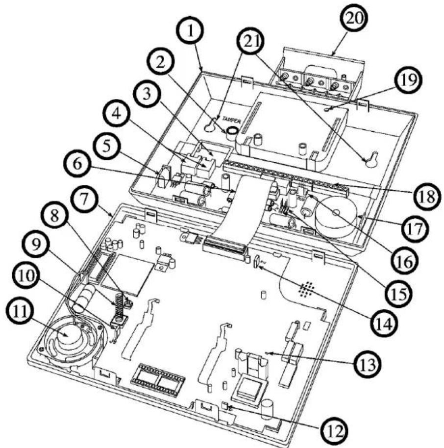
1 Base plate 12 Power voltage reset jumper
2 Case tamper opening 13 LED
3 Cable hole 14 Battery jumper
4 Telephone plug 15 Control output jumper
5 Power IN 16 BUS connection
6 Flat cable 17 Internal sounder/buzzer
7 Faceplate 18 Main connector block
8 LCD light dimmer 19 Battery case screw
9 Tamper spring 20 Battery case
10 System reset jumper 21 Wall fixing
11 Loudspeaker
5.2 How do I install the ABUS wireless alarm system?
The ABUS wireless alarm system is mounted on the wall in three steps. You need a flat screwdriver to open the casing. A battery-powered screwdriver is best suited for drilling the holes for the fixing screws. You can then use this screwdriver to screw the fixing screws into the wall.
Proceed as follows when installing the ABUS wireless alarm system:
5.2.1 Preparing the base plate
- Loosen the casing screw in the middle of the base. When delivered, the case is not yet screwed together. - Separate the faceplate and the base plate with a flat screwdriver as shown in the graphic.
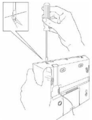
natural_image
Illustration of hands using a screwdriver to adjust or install a component, with an inset showing the tool tip (no text or symbols present)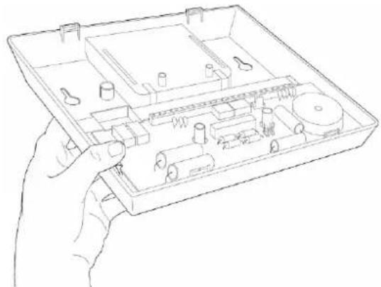
natural_image
Line drawing of a hand holding an open electronic device casing with internal components (no text or symbols)- Carefully fold the faceplate upwards. To avoid destroying the fixing clamps on the top of the faceplate, make sure you do not bend it up more than 45°.
• Now draw the flat cable out of the fixing on the base plate.
The base plate and the faceplate are now separated. Place the faceplate to one side. - Now pull the battery lid out of the base plate.
- Carefully fold the fixing clamps for the PC board outwards and pull the PC board out of the base plate.
5.2.2 Assembling the base plate
- The base plate can now be used as a drill template for marking the drill holes. 6 different drill holes are provided. At least 4 have to be used to enable stable mounting of the ABUS wireless alarm system on the wall.
Never drill the holes through the base plate since this could destroy the plastic of the base plate. Remove the PC board so that you can mark the drill holes.
• Drill the holes and insert wall plugs if necessary. Fix the base plate to the wall using M4 screws at least 35mm long. - Before screwing the base plate to the wall, remove the cable openings for telephone and power cables with side-cutting pliers (see sketch). This is not necessary if the cabling is fed through the back wall.

natural_image
Technical line drawing of a mechanical assembly with a hand operating a tool (no text or symbols present)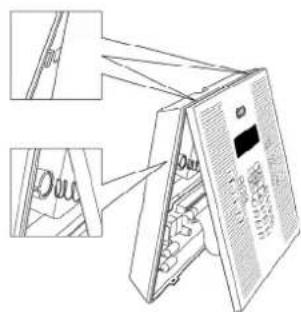
- Adjust the lid contact (tamper) according to the triggering behaviour you require: The tamper contact is on the rear of the base plate.
Box only – A tamper alarm is triggered only if the case is opened.
Box and Wall – A tamper alarm is triggered if the case is opened or removed from the wall. Select the Box and Wall setting if the system is installed on a wall. - Guide the power and telephone cables into the case. Remember that you may want to incorporate control cables, and then fix the base plate firmly to the wall using the screws provided.
- Replace the PC board.
5.2.3 Fixing the faceplate
Before fixing the faceplate, first read the following sections (up to page 5-20) and then return here. The preceding sections are not needed for every installation.
When carrying out the following, make sure that the voltage is disconnected for all connection work. Both the power adapter and the standby batteries must be disconnected.
Before fixing the faceplate, the following installation work should be complete.
• Telephone and power are connected to the PCB of the base plate (section 5.3).
- All connection work for additional control cables is completed on the PCB of the base plate (section 5.5).
• The brightness is adjusted (section 5.4).
• All jumpers are plugged in according to the desired function (section 5.7).
When all these jobs are completed, replace the faceplate and screw it tight. Proceed as follows:
- Connect the flat cable of the faceplate to the base plate.
- Insert the temper spring into the casing for the tamper opening and clip the faceplate from above into the base plate.
- Fold the faceplate down until it clicks audibly into the base plate.
- Screw the case together from below using the screw provided.
The ABUS wireless alarm system is now ready for the following installation steps described in chapter 6.
5.3 How do I install the power and telephone connections?
The ABUS wireless alarm system is powered by a 230V AC power adapter with 9V AC. In this step, make sure only the secondary power adapter plug is plugged into the base plate (see number 5 on page 5-14: What is what inside the ABUS wireless alarm system?). The power adapter plug must never be plugged into the mains socket. The socket for the power adapter is on the PCB in the base plate.
Alternatively, the power adapter plug can be connected directly to the base plate after the plug has been removed. The polarity is unimportant.
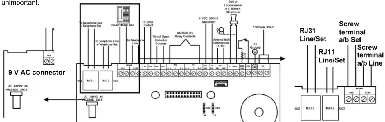
For the telephone connection, you can use either an RJ45 plug or an RJ11 plug. The two analogue telephone cables a and b can also be connected to the screw clamp as shown in the graphic. Here too, the polarity is unimportant. One or more telephone terminal devices can be connected, but they must be connected after the ABUS wireless alarm system. The reason: In the event of an alarm, the system separates the connection to any series-connected telephone terminal devices and then uses this telephone connection exclusively for transmitting the alarm message (blockade switching). In this way, you prevent a "busy" telephone from blocking the line in the event of an alarm. To connect your telephone terminal devices to the system, see the above sketch. The cables of your telephone line must be connected to the Line connector of the ABUS wireless alarm system. Connect the cables of your telephone or PBX to the Set connector.
5.4 How do I adjust the contrast of the LCD display?
The ABUS wireless alarm system has a dimmer for adjusting the brightness and contrast of the LCD display. You should make adjustments after plugging into the power supply and before replacing the faceplate on the base plate.
To make this setting, turn the LCD light dimmer (see number 8 on page 5-14: What is what inside the ABUS wireless alarm system?) carefully with a small flat screwdriver until you have set the right brightness.
5.5.1 Connecting a wired sounder
The ABUS wireless alarm system is fitted with a built-in sounder. If required, an external sounder or piezo sounder can be connected to alert inhabitants and neighbours with a loud signal during the alarm.
To connect an external sounder:
- Connect the external cables to the sounder clamps (+ Bell) (Bell -). Make sure that the polarity is correct if you are connecting an electronic sounder and/or polarised sounders.
- Select the sound signal to be generated (see chapter 8, page 8-29, Quick Key [1][2][32] in the installer menu) for each sounder.
- For a loudspeaker or built-in sounder driver, the ABUS wireless alarm system generates a continuous or interrupted oscillating voltage.
- For a sounder or electrical sounder, the ABUS wireless alarm system generates a continuous 9V DC or a slow pulsing voltage, depending on the alarm type. Use a sounder with a maximum power consumption of 9V 500mA.

WARNING:
To avoid interference to the external sounder loop if no connection is made to the sounder clamps, connect one of the 2.2 kΩ resistors supplied between the (+ Bell) and (Bell -) terminals.

NOTE:
It is very important to define the menu item Sounder / LS in the installer menu correctly. The setting depends on the type of sounder. You normally select the Sounder setting.
If the sounder output is overloaded (max. 500 mA) and it is silenced, you have to interrupt the load at the output for at least 10 seconds before reconnecting a load to the output. The circuit-breaker is then reset.
5.5.2 Sounder tamper
If a sounder tamper contact is fitted, connect the tamper contact of your (wired) sounder with the tamper input on the PC board of the ABUS wireless alarm system (Bell TMP / COM). This line is protected from tampering by a 2.2 kΩ resistor. This should be connected in series to the contact inside the sounder housing.
The tamper input is monitored only if the setting in the installer menu is set to "Yes" under "External Device" (Quick Key [1] [2] [31] in the installer menu). For more information, see [1] [2] [31].
5.5.3 Controllable relay and transistor outputs
Your ABUS wireless alarm system has 4 controllable outputs (2 x 24V DC 3A relays potential-free or 13.8V 200mA and 2 x 13.8V DC 70mA transistors). These outputs are activated according to system events. For example alarms, system faults, specific zone and partition events, but also user-controlled or time-controlled.
Connect switch outputs UO1 (switch output 1) and UO2 (switch output 2) as follows:
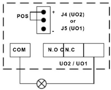
Positive: Connect the collective clamp "COM/BLK" and N.C (9V from NC) with an external device you want to control via this switch output. Take note of jumper J4 (for UO2) and J5 (for UO1). (See number 15 on page 5-14: What is what inside the system?)

Negative: Connect the collective clamp "AUX/RED" and N.C (9V from AUX) with an external device you want to control via this switch output. Take note of jumper J4 (for UO2) and J5 (for UO1). (See number 15 on page 5-14: What is what inside the system?)

Potential-free: Connect clamps c and N.C with an external power supply and an external device you want to control via this switch output. Take note of jumper J4 (for UO2) and J5 (for UO1). (See number 15 on page 5-14: What is what inside the system?)

NOTE:
- You can connect external equipment to clamp N.O instead of to clamp N.C.
If you connect to clamp NC (normally closed), the circuit between the system and an external device is closed. If the switch output is activated, the system interrupts the circuit and the connected device is switched off.
If you connect to clamp NO (normally open), the circuit between the system and an external device is interrupted. If the switch output is activated, the system closes the circuit and the connected device is switched on.
- The "COM/BLK" and "AUX/RED" clamps are collective clamps. You can connect more than one cable to them.
Connect transistor outputs UO3 (switch output 3) and UO4 (switch output 4) as follows:
Connect the positive connector of the external device you want to control with "AUX /RED" (+) clamp and the negative with the clamp of the switch output UO3 (or UO4).
5.5.4 Connecting a device ground
The grounding (earth) protects your electronic equipment against damage and interference caused by lightning and inductive voltages.
An ideal grounding is the earth connection (green/yellow wire) in the power socket.
Important: Never connect 230V directly to the system. Only the earth!
Connecting to ground:
- Make a connection between the earth contact of the ABUS wireless alarm system and an electrical earth connection to protect it against lightning and static electricity.

IMPORTANT NOTE:
The earth contact must be made in accordance with local regulations.
5.5.5 Connecting a wired zone
The ABUS wireless alarm system has a wired zone – Zone 33 (Z33), which can be used, for example, to connect a key switch or a panic emergency call. Connect this zone using twisted-pair cables or a 4-core cable. The following figure shows the different zone connection types – these have to be programmed accordingly in the installer menu later:
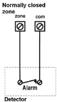

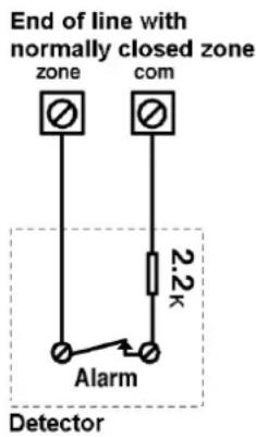


NOTE:
The wired zone cannot be used as a fire zone. For a zone with tamper, you can use a double terminal resistor (DEOL) to save additional connections.
5.5.6 Connecting an external consumer
Use the collective clamps AUX/Red (+) and COM BLK (-), to connect external devices or detectors that require a power supply of 9V DC with a maximum power consumption of 200mA.

IMPORTANT:
During a power failure, the AUX output is deactivated to ensure a longer system runtime.

NOTES:
The total current of collective clamps should not exceed 200mA.
If the collective output is overloaded (more than 200 mA) and it is silenced, you have to interrupt the load at the output for at least 10 seconds before reconnecting a load to the collective output.
5.6 How are the standby batteries used?
The ABUS alarm system is equipped with 6 standby batteries that maintain operation during a power failure. There are two types of battery:
◆ Rechargeable: Size AA, 1.2 V DC cells
Not rechargeable: Size AA, 1.5 V DC alkaline

IMPORTANT NOTE:
The batteries supplied by Security-Center are rechargeable Nickel Cadmium cells with 1.2 V 800m AAA batteries. Do not attempt to use a different type of rechargeable battery. If you do not conform with the above instructions, your equipment may suffer damage.

CAUTION:
If you use rechargeable batteries, make sure that jumper J10 is placed on its TWO pins (see also page 5-21). If you do not conform to the above instructions, persons may be injured or your equipment may suffer damage.
Inserting the batteries:
Pull out the battery case of the ABUS wireless alarm system.
- Place the 6 batteries supplied in the case. Check the polarity as shown on the case.
- Push the battery case back in.
- Secure the case with the lockable screw (if necessary).
- After making all connections, plug the power supply unit in the mains socket.

NOTE:
Recharge the batteries for at least 12 hours to ensure that they are fully charged. The “weak battery” indication should then disappear within 15 minutes.

IMPORTANT:
CAUTION: When replacing batteries, make sure you use the same type. If you do not conform to the above instructions, persons may be injured or your equipment may suffer damage.
Replacing a rechargeable battery by a non-rechargeable battery can lead to damage unless you first replace the jumper (J10) inside the ABUS wireless alarm system. For further details, see page 5-20: What are the effects of the different jumper settings?
Dispose of used batteries according to relevant regulations.
5.7 What are the effects of the different jumper settings?
The PC board of the ABUS wireless alarm system is fitted with internal jumpers. Configure the jumpers according to the function required as shown in this table:
| Jumpers on the mainboard | Position Function | |
| Restores the factory settings. (J9) |  | The J9 jumper of the ABUS wireless alarm system is used for restoring the default factory settings of your alarm system.To restore the factory settings, plug the jumper plug on to both pins of the jumper. Switch off all electricity to the system and wait at least 10 seconds. Reconnect the power supply. The factory settings are restored. You can then take off the jumper plug and plug it on to one pin.IMPORTANT: Restoring the factory settings is possible only if it was enabled in the installer menu. |
 (Default) (Default) | The default position of the jumper plug | |
| Rechargeable battery (J10) |  | Jumper J10 of the ABUS wireless alarm system is used for selecting between rechargeable batteries and normal batteries. If the jumper plug is plugged on to both pins, the batteries are recharged.IMPORTANT: As this is not the factory settings, this jumper position must be changed. |
 (Default) (Default) | Use this setting for batteries that cannot be recharged. | |
| Battery protection (J6) |  | Jumper J6 of the ABUS wireless alarm system activates/deactivates the battery discharge protection. If the jumper plug is placed on to one pin, your alarm system switches off automatically if the battery voltage falls below 6.3V DC to avoid excess discharge.NOTE:With this setting, your alarm system first starts to operate when power is available from the power supply unit. |
 (Default) (Default) | The battery discharge protection is deactivated, i.e., the battery can be completely discharged if there is a mains power failure, so that the batteries have to be replaced.NOTE:With this setting, alarm system first starts to operate when the batteries are inserted. | |
| Jumpers on the base plate | Position Function | |
| UO 1 (J5) or UO 2 (J5) |  (Default) (Default) | Defines the function of switch output 1 and switch output 2, as described in the section “wired utility outputs” on page 5-17.Default: 1 pin |
Chapter 6 Programming the ABUS wireless alarm system
There are several ways of programming your ABUS wireless alarm system:
- At the alarm system using the keypad
- At the alarm system using the PC software
- Remotely, using a telephone link and PC software
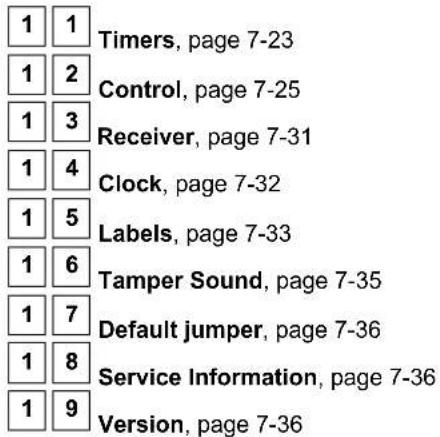
Chapter 7 Settings in installer menu
This chapter describes the options and features of the installer menu of your ABUS wireless alarm system. The following is an overview of the main menu options according to their sequence in the installer menu:
1 System, page 7-23
2 Zones, page 7-37
3 Outputs, page 7-51
4 Codes, page 7-57
5 Dialer, page 7-63
6 Not active
7 Key-fobs, page 7-71
8 Keypads, page 7-74
9 Sounder, page 7-74
0 Exit, page 7-75
7.1 Introduction to installer menu
The following pages describe the menu options for programming using the buttons of your ABUS wireless alarm system. For programming the ABUS wireless alarm system with the Downloader Software, see the separate software instructions.
To access the installer menu, deactivate the ABUS wireless alarm system, press the star button followed by 9, followed by 1.

You are asked to enter the installer code for the installer menu. If this has not been changed from the factory default, it is 0133. Enter this code and confirm by pressing the lozenge button.

You are now in the installer menu.
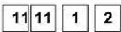
You can reach the items of the installer menu by scrolling with the buttons. When you reach the required menu option, confirm by pressing . To exit a menu option, press *. It is faster if you use the Quick-Key function. You simply enter the digits assigned to the menu option, e.g.: for menu option 111 (stands for Entry delay), press 11 11 11. Return to the main menu by pressing * three times.
These instructions are shown in columns, explained in the following table:
| Column header Description | |
| Quick-Key | The Quick-Key function is a button sequence to be pressed to reach a menu option directly. It is listed in numerical order. |
| Parameter | Name and explanation of the menu option to be programmed. |
| Default | The default factory values. The selected values are suitable for most standard applications. |
| Range | The options you can select for the menu item. |
7.2 1 System
Under System, you make settings that affect the entire system. This is an overview of the menu options according to their sequence in the System menu:
To access the System menu option:
In the installer menu, press 1 or press or until you find the number of the [1] System menu option. Then press . The first submenu (Timers) appears on the display:
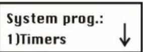
You are now in the System menu and can access the submenus, as described in the following sections.
7.2.1 1 1 Timers
Under Timers, you can make settings for delay times and alarm duration times.
To access the Timers menu option:
- Select the main menu System as described above.
- In the System menu, press 1 to get to the Timers menu option. You see the following on the display:

- Select and configure the settings as follows:
Timers:
| Quick-Key | Parameter | Default Range |
| 1 1 1 |  | |
Exit and entry delay times of Group 1. The exit delay time specifies how long you have to leave the protected area after activating the system. The entry delay time specifies how long you have to deactivate the system after entering a protected area. For more information, see the Zones menu option. To make settings for the delay times of Group 1, confirm this menu option with  or use the Quick-Key option. or use the Quick-Key option. | ||
 |  | 1-255 seconds |
 | ||
 |  | 1-255 seconds |
Exit delay time for Group 1.
Timers:
| Quick-Key | Parameter | Default Range | ||
| 1 | 1 | 2 | Exit/Entry delay 2 | |
| Exit and entry delay times of Group 2. Make these settings as for Group 1. | ||||
| 1 | 1 | 2 | Entry delay 2 45 seconds | 1-255 seconds |
| Entry delay time for Group 2. | ||||
| 1 | 1 | 2 | Exit delay 2 45 seconds | 1-255 seconds |
| Exit delay time for Group 2. | ||||
| 1 | 1 | 3 | Bell Timeout 03 minutes | 01-90 minutes |
| Duration of external sounder(s) during an alarm | ||||
| NOTE: | ||||
| In some countries, the duration of the external sounder must be limited to 3 minutes. Check the regulations for your country. | ||||
| 1 | 1 | 4 | Bell Delay 00 minutes | 00-90 minutes |
| Defines the delay between the detection of the alarm situation and sounding the alert on the sounder (of the system or the external sounder). A sounder delay is particularly useful if an alarm was first triggered by telephone without the burglar noticing it. | ||||
| 1 | 1 | 5 | AC Off Delay Time 05 minutes | 0-255 minutes |
| In the event of a power failure, this menu option defines the delay time (0-255 minutes) before the event is reported or before the switch output is activated. | ||||
| 1 | 1 | 6 | Phone Line Cut Delay 05 minutes | 01-20 minutes |
| In the event of a telephone line fault, this menu option defines the delay time before the event is reported or before the switch output is activated. | ||||
| 1 | 1 | 9 | Accessory Superv. time 255 minutes | 000-255 minutes |
| Defines the monitoring time for accessories such as interior and exterior wired sounders. To avoid false alarms, make sure that the monitoring time of the receiver (menu item 11 33 33) is longer than the monitoring time for accessories. | ||||
7.2.2 1 2 System Control
Under System Control, you make settings that control specific functions of the complete system.
NOTE:
Under this menu item, it is important that you press the lozenge button before exiting so that your data is saved. If you exit the menu by pressing, your settings are lost.
To access the System Control menu option:
- Select the main menu System as described on page 7-23.
- In the System menu, press to get to System Control. You see the following on the display:
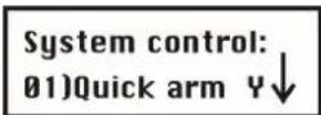
- Select and configure the settings in the System Control menu as follows:
System Control:
| Quick-Key | Parameter | Default | Range | ||
| 1 | 2 | 01 | Quick arm | YES | YES/NO |
| YES: No user PIN is necessary for activating the system or an area. NO: A user PIN is necessary for activating the system or an area. Choose this setting if the alarm system or an operating panel is accessible to the public or to children. | |||||
| 1 | 2 | 02 | Quick UO | YES | YES/NO |
| YES: A user can activate a switch output without a user PIN. NO: A user PIN is necessary to activate a switch output. | |||||
| 1 | 2 | 03 | Allow Bypass | YES | YES/NO |
| YES: A zone can be omitted (excluded from surveillance) by an authorised user. NO: Omitting zones from surveillance is not possible. | |||||
| 1 | 2 | 04 | Quick Bypass | NO | YES/NO |
| YES: No user PIN is required for omitting a zone. NO: A user PIN is required for omitting a zone. | |||||
| 1 | 2 | 05 | False Code Trouble | YES | YES/NO |
| YES: If an incorrect user PIN is entered three times, the operating panel is locked and, if programmed, an alarm is sent by telephone. Bad PIN input is displayed as a fault on the operating panel. NO: If an incorrect user PIN is entered three times, the operating panel is locked and a local alarm is sounded. | |||||
System Control:
| Quick-Key | Parameter | Default | Range |
| 1 2 06 | Bell Squawk | YES | YES/NO |
| YES: The following signals are emitted by the external sounder to acknowledge whether you have successfully activated/deactivated the system:One tone means that the system is activated.Two tones mean that the system is deactivated.Four tones mean that the system is deactivated following an alarm.NO: No confirmation is made by the sounder. | |||
| 1 2 07 | Bell 30/10 NO | YES/NO | |
| YES: The sounders interrupt the alarm tone for 10 seconds every 30 seconds.NO: The sounders emit continuous alarm tones without interruption. | |||
| 1 2 08 | Phone Cut Alarm NO | YES/NO | |
| YES: Monitors the telephone line and activates the sounder if the telephone line is cut for the period defined under Phone Line Cut Delay Time. (See also Phone Line Cut Delay time on page 7-24.)NO: The telephone line is not monitored and there is no alarm. | |||
| 1 2 09 | 3 Minute Bypass NO | YES/NO | |
| YES: After the system has been supplied with power, zones are automatically omitted for 3 minutes to give detectors a chance to stabilise.NO: The zones are monitored as soon as the system is activated. | |||
| 1 2 10 | Audible Panic | NO | YES/NO |
| YES: In the event of a panic alarm, an audible alarm is issued.NO: In the event of a panic alarm, it is transmitted by telephone. The system does not trigger any audible alarms locally. | |||
| 1 2 11 | Buzzer → Bell | NO | YES/NO |
| YES: If the system is activated internally and an alarm is triggered, an alarm is sounded for 15 seconds on the operating panels before the system activates the external sounders and the alarm is transmitted by telephone.NO: If the system is activated internally and an alarm is triggered, the external sounders and the telephone line are activated immediately. | |||
| 1 2 12 | Fire Temporal Pattern | YES | YES/NO |
| YES: The fire signals of the internal and external sounders are three increasing alarm tones followed by a pause.NO: The fire signals of the internal and external sounders are two seconds of continuous tone followed by two seconds' pause. | |||
| 1 2 13 | Code Grand Master | NO | YES/NO |
| YES: Only a user with Grand Master authority can change user PINs and the time and date.NO: Users at the Master and Manager level can also change user PINs and the time and date. | |||
System Control:
| Quick-Key | Parameter | Default | Range | ||
| 1 | 2 | 14 | Audible Jamming NO | YES/NO | |
| Refers to Jamming Time, which is described on page 7-32.YES: If the defined jamming time is reached, the ABUS wireless alarm system activates the sounders. (See Jamming Trouble, page 7-32.)NO: Jamming does not trigger an audible alarm. | |||||
| 1 | 2 | 15 | Technician Tamper NO | YES/NO | |
| YES: The program PIN is required for resetting a tamper alarm. First, the OK message must be received from the detector or the tamper zone must be closed.NO: A tamper alarm is reset with the OK message of the detector or when the tamper zone is closed. | |||||
| 1 | 2 | 16 | Technician Reset NO | YES/NO | |
| YES: Following an alarm, the program PIN must be entered to be able to reactivate the system. | |||||
| NOTE:Before the Ready LED can light up, all zones in this area must be closed. | |||||
| NO: The alarm system can be activated immediately following an alarm if all zones are closed and the Ready LED is on. | |||||
| 1 | 2 | 18 | Summer/Winter Clock | YES | YES/NO |
| YES: The ABUS wireless alarm system automatically puts its clock forward one hour forward in spring (last Sunday in March) and one hour back in autumn (last Sunday in October).NO: No automatic time adjustment | |||||
| 1 | 2 | 19 | Forced Keyswitch Arming | YES | YES/NO |
| YES: If the system or an area is activated by a key-switch, all open zones are automatically omitted from monitoring. The remaining zones are monitored. The system/area is monitored in every case.NO: The system/area can be activated only if all zones are closed and the system/area is ready for activation. | |||||
| 1 | 2 | 20 | Pager NO | YES/NO | |
Enables alphanumeric output of system events on a pager. The number of the pager must be programmed like a Follow-Me number.
YES: For the activated/deactivated event and the alarm event, the system sends information to the pager.
NO: The system transmits no events to pagers.
System Control:
| Quick-Key | Parameter | Default | Range | ||
| 1 | 2 | 21 | Arm Pre-Warning | NO | YES/NO |
| YES: For the system, or every area for which an automatic activation function was programmed, a warning signal of 255 seconds is generated on the operating panels and the alarm system prior to activation.During this countdown, you can enter a valid user code to delay automatic activation of the system/area by 45 minutes.If activation of the system/area is delayed in this way, automatic activation of the system is deactivated on the following days.The 255-second warning does not apply to automatic internal activation. | |||||
| NO: The system/area for which an automatic activation function is programmed is activated automatically every day, regardless of whether automatic activation is delayed or not. | |||||
| 1 | 2 | 22 | Low Battery Arm | YES | YES/NO |
| YES: The system can be activated even if the standby batteries are not fully charged or inserted. | |||||
| NO: The system cannot be activated in the event of a battery fault. | |||||
| 1 | 2 | 23 | Eng. Tamper NO | YES/NO | |
| YES: The system cannot be activated following a tamper alarm. The program PIN first has to be entered. | |||||
| NO: The system can be reactivated following a tamper alarm without the entry of the program PIN. | |||||
| 1 | 2 | 24 | Blank Display NO | YES/NO | |
| YES: In operation mode, the LCD display is switched off for one minute after the last input. To reactivate the display, a valid user PIN must be entered. | |||||
| NO: The LCD display is always on. | |||||
| 1 | 2 | 25 | 24 Hour Bypass | YES | YES/NO |
| YES: A user can omit a 24-hour zone. | |||||
| NO: A user cannot omit a 24-hour zone. | |||||
System Control:
| Quick-Key | Parameter | Default | Range | ||
| 1 | 2 | 26 | IMQ Install NO | YES/NO | |
| YES: | If a zone is open when the system is activated, the system is activated but an alarm is generated when the exit delay time expires. | ||||
| NO: | Open zones are automatically omitted following expiry of the exit delay time. | ||||
| 1 | 2 | 27 | Grand Master Authority/Partition | YES | YES/NO |
| YES: | Areas and authority levels can be changed by the installer in the installer menu and in the user menu using a Grand Master pin. | ||||
| NO: | Areas and authority levels can only be changed by the installer in the installer menu. | ||||
| 1 | 2 | 28 | Disarm Stop FM | YES | YES/NO |
| YES: | Forwarding of calls is stopped when the system is deactivated. | ||||
| NO: | Forwarding of calls is continued even if the system is deactivated. | ||||
| 1 | 2 | 29 | Notes | ||
| If a block lock is used, you can deactivate the system only if the block lock is opened. | |||||
| However, if the system is deactivated by telephone, the calls are continued. | |||||
| Global Follower NO | YES/NO | ||||
| YES: | Specifies that all zones (that are programmed to follow an exit/entry delay time) follow the exit/entry delay time of ALL activated areas - i.e., that the system is not activated until after expiry of the longest exit delay time. | ||||
| NO: | Specifies that all zones (that are programmed to follow an exit/entry delay time) will only follow an exit/entry delay time of the area for which they are defined. | ||||
| 1 | 2 | 30 | Area NO | YES/NO | |
Changes the function of the system as follows:
YES: A zone assigned to more than one area is not monitored until all areas are activated, and it continues to be monitored until all areas are deactivated.
NO: A zone assigned to more than one area is not monitored until all areas are activated, and it continues to be monitored until one area is deactivated.
System Control:
| Quick-Key | Parameter | Default | Range | ||
| 1 | 2 | 31 | External Bell NO | YES/NO | |
| YES: Select this setting if an external sounder is connected to the wireless alarm system. The ABUS wireless alarm system monitors the (+) (-) connections as well as BELL TMP and COM and reports faults, events, alarms and reports. To avoid a fault in the signalling device if no sounder is connected, insert a 2.2 KΩ resistor instead.To avoid a tamper alarm when no connection exists to the BELL TMP COM stations, use a 2.2 KΩ resistor instead.NO: Select this setting if no external, wired sounder is connected to the ABUS wireless alarm system. The (+) (-) connections as well as BELL TMP and COM are not monitored. | |||||
| 1 | 2 | 32 | Loudspeaker-No / NO | YES/NO | |
| Bell-Yes | |||||
| YES: (For a signalling device or electrical sounder) A 9 V DC voltage is generated on the sounder connection during a burglar alarm or a panic alarm. A low pulse voltage is generated during a fire alarm.NO: (For a loudspeaker with no built-in driver for sounders) The ABUS wireless alarm system generates a continuously fluctuating pulse voltage for burglar and panic alarms and an interrupted fluctuating pulse voltage for fire alarms. | |||||
| 1 | 2 | 35 | SRN Pre-alr NO | YES/NO | |
| An important security aspect for your security system if you have fitted internal and external sounders.YES: At the start of the entry delay time, the system sends a signal to the trained sounders. If no second signal is sent to the sounder following expiry of the delay time (since the system may have been destroyed or tampered with), the sounders trigger an alarm.NO: The function is deactivated. The sounders start to sound an alarm when addressed by the system. | |||||
7.2.3 1 3 Receiver
Under Receiver, you can make settings that control the radio receiver of your ABUS wireless alarm system.
To access the Receivers menu option:
- Select the main menu System as described on page 7-23.
- In the System menu, press 3 to go to the Receivers menu option. You see the following on the display:
Receiver:
1) Calibration

- Select and configure the settings in the Receiver menu as follows:
Receiver:
| Quick-Key | Parameter | Default Range |
| 1 3 1 | Calibration |
During calibration, the radio receiver measures the level of the electromagnetic background noise. The lower the level, the better the selected installation location. Additionally, the level set decides the strength of the electromagnetic field above which the alarm system interprets this as a conscious tamper attempt.
Range of level: 00-99.
- Press 1. The following appears on the display and specifies the current level:
Thold=00
Re-calibrate?

To conduct a new automatic measurement, press and select [Y] YES. After measurement is complete, the new level is displayed as follows:
Thold=XX
New Thold=XX
To confirm the new level, press OR:

to change the level manually, enter the desired level and press

NOTES:
To ensure that a measured low value (due to the environment) does not trigger a fault alarm in later operation, you can set the level higher as the measured value. Never reduce the measured level, since this will lead to a fault alarm in later operation.
Receiver:
| Quick-Key | Parameter | Default Range | |||
| 1 | 3 | 2 | Jamming Time | No Jamming detection | None, 10, 20 or 30 seconds |
| The jamming time specifies the time within one minute in which the level of the background noise can be above the value measured under “Calibration” (or above the manually set value). | |||||
| NOTE: | |||||
| A fault is displayed only if the “Audible Jamming” option was enabled in the system control. | |||||
| 1 | 3 | 3 | Supervisory Time 0 hours | 0-7 hours | |
| The wireless detectors automatically send a message to the ABUS wireless alarm system every 65 minutes. This message also contains information on the battery state and the current alarm state. The wireless alarm system can now monitor whether these messages are regularly transmitted. Within the set monitoring time, at least one message per detector must be transmitted. | |||||
| NOTES: | |||||
| The setting “0 hours” aborts monitoring.You are recommended to set the monitoring time to a minimum of 3 hours. | |||||
| 1 | 3 | 4 | Delete detectors | ||
| Deletes all trained wireless detectors simultaneously. To delete the wireless detectors, confirm the setting by pressing . To exit this menu option without deleting detectors, press .* | |||||
| NOTES: | |||||
| If the J9 jumper was placed on both pins, this menu appears first in the installer menu. | |||||
7.2.4 1 4 Set Clock
Under Set Clock, you set the system date and time.
To access the Set Clock menu:
- Select the main menu System as described on page 7-23.
- In the System menu, press 4 to get to the Clock menu option:
System Clock: 1) System time
- Select and configure the settings in the Set Clock menu as follows:
Set Clock:
| Quick-Key | Parameter | Default Range |
 | System Time 00:00 | HH:MM |
Sets the current time in 24-hour format. Enter the current time on the operating panel keypad. Click  e forwards or backwards in the display. e forwards or backwards in the display. | ||
 | System Date 01 JAN 2007 (MON) | DD MM YYYY(DAY) |
Sets the current date. Enter the date and the year via the keypad. Clickor  to move forwards or backwards in the display. Change the month by pressing to move forwards or backwards in the display. Change the month by pressing  | ||
Under System Label, you name the system and areas 1, 2 and 3, and change default names.
To enter a new name:
Use the buttons of your ABUS wireless alarm system to enter the letters as shown in the table below. When you press a specific button, you scroll backwards and forwards through the characters. The ABUS wireless alarm system permits a total of 75 characters for a name (letters, numbers and symbols).
| BUTTON PRODUCES THE LETTERS | |||||||||||||||
| 1 | 1 | A | B | C | D | C | F | G | H | I | Y | K | |||
| 2 | 2 | N | O | P | Q | R | S | T | U | V | W | X | Y | ||
| 3 | 3 | & | : | - | . | ? | / | ( ) | |||||||
| 4 | 4 | a | b | c | d | e | f | g | h | i | j | ||||
| 5 | 5 | n | o | p | q | r | s | t | u | v | w | X | |||
| 6 - 0 | Each of these buttons scrolls backwards and forwards between number and space. | ||||||||||||||
 | Press this button to scroll forwards between the available characters. | ||||||||||||||
 | Press this button to scroll backwards between the available characters. | ||||||||||||||
 | Press this button to move the cursor to the left. | ||||||||||||||
 | Press this button to move the cursor to the right. | ||||||||||||||
 | Press this button to store a name. | ||||||||||||||
The number of characters permitted varies for each name as follows:
• Zone label: up to 15 characters
• Partition label: up to 12 characters
• Programmable output label: up to 12 characters
• Label of a message to the user: up to 12 characters
• Label for service information: up to 16 characters
• Label for a service name: up to 16 characters
• System label: up to 16 characters
• Label for a user: up to 10 characters
To access the System Label menu:
- Select the main menu System as described on page 7-23.
- In the System menu, press 5 to get to the System Label menu option. You see the following on the display:
Labels:
1) System
- Select and configure the settings in the System Label menu as follows:
System Label:
| Quick-Key | Menu | option | Default Selection | ||
| 1 | 5 | 1 | System | FUNKALARMANLAGE | Any 12 characters |
| Changes the display for the system name. | |||||
 | Partitions 1 – 3 | Partitions 1–3 | Any 12 characters | ||
Changes the display for partitions 1 to 3.
Example: The example below shows how to change the name of partition 1 to "Buero"
To assign the label "Buero" to partition 1:
- Press 2 for partition 1.
- Press 1 three times until the letter B appears on the display and then press once to move the cursor to the right.
- Press 5 repeatedly until the letter u appears on the display and then press again to move the cursor forwards.
- Press 4 repeatedly until the letter e appears on the display and then press to move the cursor forwards.
- Press 5 repeatedly until the letter r appears on the display and then press again to move the cursor forwards.
- Press 5 repeatedly until the letter o appears on the display and then press again to move the cursor forwards.
- Press 6 twice for a space and then press to move the cursor forwards. In this way, delete the unwanted characters.
7.2.6 1 6 Tamper Sound
In the Tamper Sound menu, you can define the sounds generated by the ABUS wireless alarm system following a tamper in a zone, the ABUS wireless alarm centre housing, the wireless operating panel, or any other device. You can also adjust the sounder volume for alarms and their acknowledgement.
To access the Tamper Sound menu:
- Select the System menu as described on page 7-23.
- In the System menu, press 6 to access the menu option of the Tamper Sound menu. You see the following on the display:
Tamper sound: 5) Bell/A Buz/D
- Select and configure the settings in the Tamper Sound menu as follows:
| Tamper Sound: | |||
| Quick-Key | Parameter | Default Range | |
| 1 6 1 | Tamper sound Bell/A Buzzer/D | 1 to 5 | |
| Programs the signals generated by a tamper alarm. | |||
| Setting | Sound | ||
| 1 | Silent | ||
| 2 | Bell only (external sounder) | ||
| 3 | Buzzer only (piezo on operating panel) | ||
| 4 | Bell and buzzer | ||
| 5 | Bell/Arm, Buzzer/Disarm | ||
| NOTE: | |||
| If you set sounder/active and buzzer/inactive, the system will activate only the buzzer when in deactivated state. If the system is active, the external sounder is also activated. | |||
| 1 6 2 | Speaker Volume | ||
| Adjusts the volume of the integrated sounder in the event of an alarm and for acknowledgement. | |||
| 1 6 2 1 | Alarm 5 | 0 to 5 | |
| If you confirm this menu option, the sounder is activated briefly at the volume defined. You can adjust the volume with buttons 0 to 5.The setting 0 deactivates the sounder, and 5 is the loudest setting. | |||
| 1 6 2 2 | Squawk 5 | 0 to 5 | |
| If you confirm this menu option, the sounder is activated briefly at the volume defined. You can adjust the volume with buttons 0 to 5.The setting 0 deactivates the sounder, and 5 is the loudest setting. | |||
7.2.7 1 7 System Default Jumper
In the Default Jumper menu, you enable or disable a software factory reset via the J9 jumper.
To access the Default Jumper menu:
- Select the main menu System as described on page 7-23.
- In the System menu, press 7 to access the Default Jumper menu option. You see the following on the display:
Default jumper: (J9) is enabled
-
Press to select one of the following settings:
-
Enabled: The ABUS wireless alarm system can be completely reset to its original default (factory) settings by switching off and on the complete power supply and with the help of the J9 jumper. All settings, labels, PIN codes, etc. are reset to the factory settings.
- Disabled: The ABUS wireless alarm system cannot be reset by changing the J9 jumper and switching on and off.
7.2.8 1 8 Service Information
The Service Information menu enables you to enter details about the vendor of the system (name, telephone number, etc.).
To access the Service Information menu:
- Select the main menu System as described on page 7-23.
- In the System menu, press 8 to access the Service Information menu option. You see the following on the display:
Service Info: 1) Service Name ↓
- Select and configure the parameters in the Service Information menu as follows:
| Service Information | ||||
| Quick-Key | Menu | option | Default Selection | |
| 1 | 8 | 1 | Service Name | Any 16 characters |
| Enter the vendor's name. | ||||
| 1 | 8 | 2 | Service Number | Any 16 characters |
| Enter the vendor's telephone number. | ||||
7.2.9 1 9 Version
The Version menu shows the current version of the alarm system.
To access the Version menu:
- Select the main menu System as described on page 7-23.
- In the System menu, press 9 to get to the Version menu option.
The version of the system with the checksum number of the software is displayed.
7.3 2 Zones
The Zones menu enables you to train wireless detectors for the system, program zone types, and define zone dependencies. This is an overview of the menu options according to their sequence in the Zones menu:
To access the Zones menu:
In the installer menu, press 2 or press or until you find the number of the Zones [2] menu option. Then press . The first submenu Allocation appears on the display:
Zones: 1) Allocation
You are now in the Zones menu option and can access the submenus, as described in the following sections.
7.3.1 2 1 Allocation
Under Allocation, you can make settings for learning and deleting zones.
For additional information, refer to the instructions supplied with the wireless detectors.
To access the Allocation menu:
- Select the Zones menu as described on page 7-37.
-
In the Zones menu, press 1 to access the Allocation menu option.
-
Enter the two-digit number of the zone you want to edit and press You see the following on the display:


Jumps to the next zone number.
(Re) Write
Trains new wireless detectors to work with the alarm system. When you select this menu option, a countdown of 255 seconds begins. If you trigger the wireless detector within this time (as described in these instructions), the detector sends a learn message. If the signal is received, the alarm system acknowledges it with an acknowledgement tone. To cancel the learning procedure, press .*

Delete
Deletes detectors. Confirm deletion with [Y] YES or [N] NO. To change the display, press

Supervision
Select whether a zone is to be monitored for regular reporting by the detectors to the alarm system. Set the monitoring time in the System menu under Timers. If surveillance is active for the detector and the detector does not report in the defined time, an alarm is triggered. Select [Y] YES or [N] NO. To change the
display, press . To confirm, press .

7.3.2 2 2 Parameters
Under Parameters, you can make settings for programming properties of the zones. You can program all settings one by one for a zone, or you define the respective parameters for all zones. If this is your first installation, you are recommended to select One by One. If you make changes later, you can program the parameters directly in this menu.
You can first program the zones and then train the wireless detectors, or vice versa.
• One by one
- Zone Label
- Partitions
- Type
- Zone Sound
- Force Arming
Parameter
| Quick-Key | Parameter | Default Range |
| 2 2 1 | One by one |
The one by one option enables you to program the parameters individually for each zone – i.e., one zone after the zone.
- Enter a two-digit number to start programming (e.g. 01) and press access the zone label menu option.
- Enter a name for the zone and press to go to the next menu option.
- Press [1] to [3] to switch the state of the partition between [Y] YES and [N] NO. A zone must be assigned to at least one area. Press to go to the next menu option.
- To program the zone type and make the other settings for the zone, select the following menu options.
Type: Select a type and press
Zone sound: Select a signal type and press

For further information about zone types and zone signals, see the next pages.
Parameter
Quick-Key
Parameter
Default Range
IMPORTANT INFORMATION:
- If you selected one by one to program the zones individually, you are guided step by step through the programming points for the zones.
- To save settings for the zone, you have to work through all menu options. If you exit programming early by pressing the star button, your settings are not saved.
After working through all menu options menu, press 1.4 second tone sounds and confirms that your settings for this zone are saved. You go automatically to the next zone.
Zone 33 (wired zone)
Zone 33 is defined in the ABUS wireless alarm system as a wired zone. For this reason, it has two extra parameters following the Zone sound menu item that are applicable to this wired zone only:
- Zone termination
- Zone loop response
Zone termination
A wired zone is monitored using a weak electric current. The electric current is defined by the resistor used. You can terminate a zone as follows:
- N/C: (= normally closed) a zone termination is not necessary. It is important to use detectors that open the circuit in the event of an alarm.
- EOL: (= single resistor) a zone termination with a resistor (2.2kOhm / red, red, red, gold) is required. It is important to use detectors that open the circuit in the event of an alarm.
- DEOL: (= double resistor) a zone termination with two resistors (2.2kOhm / red, red, red, gold) is required. One resistor is inserted parallel to the tamper contact of the detector. It is important to use detectors that open the circuit in the event of an alarm.
- N/O: (= normally open) a zone termination is not necessary. It is important to use detectors whose circuit closes in the event of an alarm.
To see how to wire a detector, see page 5-18.
NOTE:
For more information, see the wiring notes at the beginning of these instructions.
Zone loop response
Under zone loop response, you program the time that the wired zone has to be open (closed) before an alarm is triggered.
The following options are available:
1) Normal: 400 ms (milliseconds) 7) 2 hours
2) Long: 1 second 8) 2.5 hours
3) Fast: 10 ms (milliseconds) 9) 3 hours
4) 30 minutes 10) 3.5 hours
5) 1 hour 11) 4 hours
6 ) 1.5 hours
2 2 2
Zone Label
Under Zone label, you can define or edit a name up to 15 characters long for each zone.
Under Parameters, press 2 to access the zone label menu option. You see the following on the display:
Zone label:
Zone:01 (01-33)

Press to name Zone 01 or enter a different zone number. You see the following on the display:
Zone label: 01
Zone 01
Edit the zone name as described on page 8-34.
2 2 3
Zone Partition
Partitions 1–3
Under Partition, you assign zones to different areas. This is necessary in larger systems to distinguish, for example, between the commercial area (shop) and the private area (home), when both are monitored by the ABUS wireless alarm system.
Under Parameters, press 3 to access the Partition menu option. The following appears on the display:
Zone partition:
Zone: 01 (01-33)
Enter a two-digit zone number and press 📄. You see the following on the display:
P=123
Z=XX
Y..

NOTE:
You can assign a zone to one or more areas. The Y under the number shows the area (1, 2, 3) to which the zone is assigned. A zone that is assigned to more than one area is not monitored until all assigned areas are activated.
Press [1] to [3] to switch the state of the areas between [Y] YES and [N] NO.
2 2 4
Zone Type
When a detector triggers, it always sends a signal to the alarm system. For example: A motion sensor reacts to movement, a smoke detector to smoke, etc. So it is important to tell the system HOW and WHEN it is to react to a signal from a detector.
Under Zone type, you can program the behaviour of the alarm system when it receives a signal from a detector. It is absolutely necessary to program this behaviour since your alarm system will not work without it. The following zone types are monitored, depending on the state of the alarm system:
- Disarm: The system reacts to the following zones only: 24-hour, fire, panic and fault.
- Arm: The system reacts to all zones.
- Stay (Internal arm): The system does not react to zones you have programmed as internal zones. This setting enables you to move within the object when the perimeter is protected.
There are 22 zone types, whose properties are described in the following:
Under Parameters, press 4 to get to the Zone type menu option. You see the following on the display:
Zone type:
Zone:01 (01-33)

Enter a two-digit zone number and press
Select and configure the zone types as follows:
Zone Type
| Quick-Key | Menu | option | Default | Selection |
| 2 2 4ZZ +#00 | Not used | NONE | ||
| A zone programmes as not used is not monitored. The alarm system reacts neither to battery faults, tampering, nor monitoring failure of the detector trained for this zone. However, a trained detector is not deleted. | ||||
| 2 2 4 ZZ +#01 | Exit/Entry 1 | Armed/internal | ||
| A zone programmed as Exit/Entry 1 must not be opened during the exit delay time without an alarm being triggered. However, the zone must be closed before the exit delay time expires. If the zone is opened when the alarm system is active, the entry delay time of Group 1 (to be programmed under System/Timers) is started. The area of the wireless alarm system must be deactivated in this time. If not, an alarm is triggered following the expiry of the delay period. Detectors trained for a zone with this property are usually fitted to front and side doors. This zone must be closed at the moment of activation. If this cannot always be guaranteed, choose the zone type Exit(OP)/Entry | ||||
| 2 2 4 ZZ +#02 | Exit/Entry 2 | Armed/internal | ||
See above. However, for zones of this type, the times of Group 2 apply.
| Zone Type | ZZ + | Exit(OP)/Entry | Default for zone 1 | Armed/internal |
 | Menu option | Default | Selection | |
 | Not used | NONE | ||
 | ||||
 | ||||
 | ZZ + | Entry followingmes as not used is not monitored. The alarm system is not monitored. The alarm system is neither to battery faults, tampering, nor monitoring failure of the detector trained for this zone. However, a trained detector is not deleted. | ||
 | ||||
 | ZZ + | Exit/Entry 1 | Armed/internal | |
 | to opening contacts on the entrance doors.A zone programmed as Exit/Entry 1 must not be opened during the exit delay time without an alarm being triggered. However, the zone must be closed before the exit delay time | |||
 | ZZ + | Instant. If the zone is opened when the alarm system is active, the entry delay time of Group 1 (to be programmed under System/Timers) is started. The area of the wireless alarm system must be deactivated in this time. If not, an alarm is triggered following the expiry of the delay period. Detectors trained for a zone with this property are usually fitted to from and side above. The zone zone type is closed at the moment of activation on the cannot open and the zone does not be opened during Exit(OR)/Entry exit delay period. This is the usual zone type for motion and opening sensors that are not in the entrance area. | ||
 | ||||
 | ZZ + | Exit/Entry 2 | Armed/internal | |
 | ZZ + | |||
 | See above. However, for zones of this type, the times of Group 2 apply.The I+Exit/Entry 1 zone type is similar to zone type Exit/Entry 1. However, this zone type is not monitored for an internally activated system. | |||
| IMPORTANT INFORMATION:To shorten the exit delay time, press twice. This sets the entry delay time to 0. If this zone is now opened, there is an immediate alarm. | ||||
 | ZZ + | I+Exit/Entry 2Interior+Exit/Entry 2) | Armed | |
 | See above. However, for zones of this type, the times of Group 2 apply. | |||
 | ZZ + | I+Exit(OP)/Entry (Interior+Exit(OP)/Entry) | Armed | |
 | The I+Exit(OP)/Entry zone type is similar to zone type Exit(OP)/Entry. However, this zone type is not monitored for an internally activated system. | |||
 | ZZ + | I+Entry follow (Interior+Entry Follower) | Armed | |
 | The I+Entry follow zone type is similar to zone type Entry Follower. However, this zone type is not monitored for an internally activated system. | |||
2 2 4 ZZ +  | Exit(OP)/Entry | Default for zone 1 | Armed/internal | |
| Zone type Exit(OP)/Entry behaves like zone type Exit/Entry 1 except that the zone does not have to be closed at the moment of activation. However, the zone must be closed before the exit delay time expires, or otherwise there is an alarm. This zone type is usually assigned to opening contacts on front and side doors. | ||||
2 2 4 ZZ +  | Entry follower | Armed/internal | ||
| Zone type Entry follower does not trigger an alarm if an entry delay time is started first. If no entry delay is active, this zone triggers an alarm immediately if the area is activated. This zone type is usually assigned to motion sensors that monitor the entrance area, in addition to opening contacts on the entrance doors. | ||||
2 2 4 ZZ +  | Instant | Armed/internal | ||
| If the area is active, the Instant zone type triggers an alarm immediately when the zone is opened. This zone must not be opened during the entry and exit delay period. This is the usual zone type for motion and opening sensors that are not in the entrance area. | ||||
2 2 4 ZZ +  | I+Exit/Entry 1 (Interior + Exit/Entry 1) | Default for zone 2 | Armed | |
| The I+Exit/Entry 1 zone type is similar to zone type Exit/Entry 1. However, this zone type is not monitored for an internally activated system. | ||||
| IMPORTANT INFORMATION:To shorten the exit delay time, press twice. This sets the entry delay time to 0. If this zone is now opened, there is an immediate alarm. | ||||
2 2 4 ZZ +  | I+Exit/Entry 2 (Interior+Exit/Entry 2) | Armed | ||
| See above. However, for zones of this type, the times of Group 2 apply. | ||||
2 2 4 ZZ +  | I+Exit(OP)/Entry (Interior+Exit(OP)/Entry) | Armed | ||
| The I+Exit(OP)/Entry zone type is similar to zone type Exit(OP)/Entry. However, this zone type is not monitored for an internally activated system. | ||||
2 2 4 ZZ +  | I+Entry follow (Interior+Entry Follower) | Armed | ||
| The I+Entry follow zone type is similar to zone type Entry Follower. However, this zone type is not monitored for an internally activated system. | ||||
2 2 4 ZZ +  | I+Instant (Interior+Instant) | Armed | ||
| The I+Instant zone type is similar to zone type Instant. However, this zone type is not monitored for an internally activated system. | ||||
2 2 4 ZZ +  | UO Trigger | Armed | ||
| The UO Trigger zone type controls a switch output whether the system is active or inactive. For example: for temperature sensors that control a ventilator. | ||||
 ZZ + #1 12 ZZ + #1 12 | Day Zone | Armed | ||
| A zone with the Day Zone zone type immediately triggers an alarm in an internally or externally activated system. If the system is inactive, a fault is displayed on the alarm system display. The fault message can now control a switch output or be viewed by the user in the user menu under Troubles. This zone type is mostly used to protect emergency exits. | ||||
 ZZ + #1 13 ZZ + #1 13 | 24 Hours | Default for zone 3 All | ||
| A zone with the 24 Hours zone type triggers an alarm immediately, irrespective of the state of the alarm system. This zone type is mostly used for passive glass breakage sensors. | ||||
 ZZ + ZZ +  | Fire | Default for zone 3 All | ||
| A zone with the Fire zone type triggers a fire alarm immediately, irrespective of the state of the alarm system. This zone type is used for smoke detectors. | ||||
| NOTE:Zone 33 cannot be programmed as a fire zone. | ||||
 ZZ + ZZ +  | Panic | All | ||
| A zone with the Panic zone type triggers a panic alarm immediately, irrespective of the state of the alarm system. This zone type is not intended for panic messages triggered by remote control. See the key-fob menu. | ||||
 ZZ + ZZ +  | Special | All | ||
| A zone with the Special zone type triggers a medical emergency alarm (not a panic alarm) immediately, irrespective of the state of the alarm system. | ||||
 ZZ + ZZ +  | Pulse Keyswitch | |||
| A zone with the Pulse Keyswitch zone type can be used to activate/deactivate an area. The state change must be in the form: closed – open (pulse) – closed. | ||||
 | I+Instant(Interior+Instant) | Armed | ||
| Anone instan the Exit Tokenisation zone type dehasten te r a wze, with the Ex(WOR)Entryzone type. However the difference is not an exit delay time is ended immediately if thiszone is opened or closed during the exit delay time. | ||||
      | UO Trigger | Armed | ||
| The UO Trigger zone type controls a switch output whether the system is active or inactive.For example: for temperature sensors that control a ventilator.A zone with the Latch Keyswitch zone type is used for activating/deactivating one or more areas. The area remains active as long as the zone is open, and is deactivated Day Zone | Armed | |||
| A zone with the Day Zone zone type immediately triggers an alarm in an internally or externally activated system. If the system is inactive, a fault is displayed on the alarm system display. The fault message can now control a switch output or be viewed by the user of this zone work like Zone type. Zone types is mostly used to protect emergency works like an exit/entry zone of Group 1. | ||||
  | 24 Hours | Default for zone 3 All | ||
| A zone with the Key switch Relay zone type is used for activating/deactivating the state or more alarm system. This zone type is mostly used to provide key switch leakage season that the area is first activated following expiry of the entry/exit delay time of Group 1. | ||||
  | Fire | Default for zone 3 All | ||
| A zone with the Fire zone type triggers a fire alarm immediately, irrespective of the state of the alarm system. This zone type is used for smoke detectors.A zone with the Latch KSW Delay zone type is used for activating/deactivating one or more areas. The area remains active as long as the NOTE:Zone 33 cannot be programmed as a fire zone type is comparable to Zone type Blockschloss, except that the area is first activated following expiry of the entry/exit delay time of Group 1. | ||||
   | ||||
| A zone with the Panic zone type triggers a panic alarm immediately, irrespective of the state of the alarm system. This zone type is not intended for panic messages triggered by remote control. See the key-fob menu. | ||||
  | Special | All | ||
| A zone with the Special zone type triggers a medical emergency alarm (not a panic alarm) immediately, irrespective of the state of the alarm system. | ||||
  | Pulse Keyswitch | |||
A zone with the Pulse Keyswitch zone type can be used to activate/deactivate an area. The state change must be in the form: closed – open (pulse) – closed.
 | Exit Termination |
| A zone with the Exit Termination zone type behaves like a zone with the Exit(OP)/Entry zone type. However, the difference is that an exit delay time is ended immediately if this zone is opened or closed during the exit delay time.When you enter the protected area, the entry delay time of Group 1 starts as usual. | |
 | Latch Keyswitch |
| A zone with the Latch Keyswitch zone type is used for activating/deactivating one or more areas. The area remains active as long as the zone is open, and is deactivated as soon as the zone is closed. | |
 | Entry Follower + Stay (Internal) |
| If armed, this zone works like a zone type Entry Follower. If stay armed this zone type works like an exit/entry zone of Group 1. | |
 | Keyswitch Delay |
| A zone with the Keyswitch Delay zone type is used for activating/deactivating one or more areas. This zone type is comparable to zone type Key switch, except that the area is first activated following expiry of the entry/exit delay time of Group 1. | |
 | Latch KSW Delay |
| A zone with the Latch KSW Delay zone type is used for activating/deactivating one or more areas. The area remains active as long as the zone is open, and is deactivated as soon as the zone is closed. This zone type is comparable to zone type Blockschloss, except that the area is first activated following expiry of the entry/exit delay time of Group 1. |
2 2 5
Zone Sound
Under Zone sound, you can, for each zone, define the alarm signal individually that is triggered when the alarm system is active.
- Under Parameters, press 5 to access the Zone sound menu option. You see the following on the display:
Zone sound:
Zone:01 (01-33)

-
Enter a two-digit number and press
-
Select and configure a zone signal for each zone.
Zone sound
| Quick-Key | Parameters | Default Range |
  | Silent | |
| No audible alarm is generated. An alarm is transmitted by telephone only. | ||
  | Bell Only | |
| Activates the external and internal sounders for the defined sounder duration or until a valid user code is entered and the # key is pressed. | ||
  | Buzzer Only | |
| Activates the piezo buzzer of the alarm system. | ||
  | Bell + Buzzer Default for all zones | |
| Activates the piezo buzzer plus the internal and external sounders. The sounders switch off when the programmed sounder duration expires. | ||
  | Door Chime | |
| If the system is inactive, this causes the piezo buzzer of the alarm system to emit 3 short beeps. If the system is active, the internal and external sounders are activated. | ||
  | (Bell/A Buzzer/D) | |
If the system is inactive, this activates the piezo buzzer of the alarm system, and if the system is active, the internal and external sounders are activated.
2 2 6
Force Arm
The Force Arm setting for a zone enables the system to be activated even if one or more zones are open, provided these zones were programmed with this setting.
- If such a zone is open, the "ready" system LED flashes.
- After the system is activated, all open zones programmed as Force Arm are automatically excluded from monitoring.
- If such a zone is closed in active status, it is returned to monitoring.
To program a zone with the Force Arm setting:
- Under Parameters, press to access the Force Arm menu option. You see the following on the display:
Forced ARM:
Zone:01 (01-33)
- Enter the zone number for which you want to program for Forced Arming and press

- Press or to select Enable or Disable and then press
Repeat steps 1 to 3 to program this settings for the other zones.
Press to exit the menu option.
7.3.3 2 3 Zone Testing
Under Testing, you can check the correct functioning of zones.
To access the Testing menu:
- Select the Zones menu as described on page 7-37.
- In the Zones menu, press 3 to access the Testing menu option. You see the following on the display:
Zone testing
01)WL.comm.test↓
2 3 1
Wireless Communication Test
Runs a communication test between the wireless detector and the ABUS wireless alarm system.
- Press 1. You see the following on the display:
Zone comm.test:
01)Zone 01 :00
- To run the communication test, trigger the detector. If reception is successful, the alarm system shows the signal strength. A successful test is confirmed by a beep on the alarm system.
NOTE:
For successful communication, the signal strength (= displayed value) should be higher than the noise level of the transmitter (see also page Calibration).
- Press 📋 or to select the zone number of the next wireless detector.
- Press ✱ to exit the menu option.
2 3 2
Soak Test
Some wireless detectors tend to trigger alarms more than others. The Soak Test was developed to test these detectors over a longer period without triggering an alarm.
Up to 8 zones can be programmed for the Soak Test. A zone programmed for the Soak Test is omitted for 14 days while the alarm system is active. If no alarm is triggered by this detector for 14 days, the tested zone is automatically reintegrated in the system.
If one of the zones programmed for the Soak Test sends an alarm within these 14 days, the alarm system does not trigger an alarm but registers a fault message instead. You can see the fault message in the user menu.
The 14-day period for the joint test of alarm lines is then set to zero and restarted.
To add a zone to the Soak Test:
Press 2. You see the following on the display:
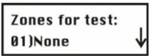
To add a zone to the Soak Test, press 📋. You see the following on the display:
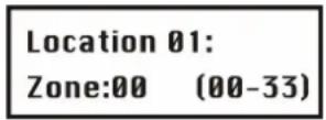
Enter the zone number (e.g., 01 for Zone 1) and press 📃. The menu jumps to the next assignment number.
To add a second zone to the Soak Test, press and repeat the above procedure
- OR -
Press * to return to the previous menu.
If you enter zone number 00, no zone is assigned to the Soak Test.
7.3.4 2 4 Editing
Under Editing, you can copy and delete programmed zones.
To access the Editing menu:
- Select the Zones menu as described on page 7-37.
- In the Zones menu, press 4 to get to the Editing menu option. You see the following on the display:
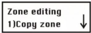
Editing
| Quick-Key | Parameter |
| 2 4 1 | Copy to a zoneCopies all settings programmed for a zone (except the zone name).1. Press 1. You see the following on the display:Copy zone:From:01 To:012. Press the number buttons 1 to 9 to select the zone you want to copy and pressor to move the cursor. Press 1 to 9 again to select the zone to which you want to copy.The procedure is confirmed with a beep if successful.3. Press *to exit the menu option. |
| 2 4 2 | Delete a ZoneDeletes a zone. The zone is not completed deleted, but its zone type is set to “not used”. The zone settings are retained.1. Press 2.2. Press or or the number buttons 1 to 9 to select the zone you want to delete.3. Press to switch between [Y] YES and [N] NO and press # to confirm.4. Press *to exit the menu. |
| 2 4 3 | Add/Copy PartitionCopies a partition to another partition.1. Press 3.2. Press the number buttons 1 to 3 to select the area you want to copy and pressor to move the cursor. Press the number buttons 1 to 3 again to select the area to which you want to copy.The procedure is confirmed with a beep if successful.3. Press *to exit the menu option. |
| 2 4 4 | Delete a partitionDeletes a selected partition. All zones assigned to this partition are also deleted.1. Press 4.2. Press the cursor keys to select the area you want to delete.3. Press to switch between [Y] YES and [N] NO and press # to exit the program.4. Press *to exit the program. |
7.3.5 2 5 Cross Zone
Default: No cross-zone dependency
Cross-zone dependency is an ideal function for making a system safer against false alarms. Using cross-zone dependency, two zones have to trigger an alarm within a specific period and in a defined or undefined sequence before the alarm system generates an alarm.

NOTE:
The ABUS wireless alarm system enables you to program 10 of these zone pairs.
To access the Cross Zone menu:
- Select the Zones main menu as described on page 7-37.
- In the Zones menu, press 5 to get to the Cross Zone menu option. You see the following on the display:
Zone crossing: 01) 01 with 01
- Press to define the first pair (01) of cross-dependent (interdependent) zones.
Crossing set 01: 1st=01 2nd=01
- You select a zone pair by entering the number of the first zone followed by the number of the second zone. If necessary, press or to switch between the first and second zone.

NOTE:
Zones defined as mutually interdependent are considered as a zone pair. They both have to report an alarm before the system triggers an alarm.
-
Press to define how the ABUS wireless alarm system deals with cross-zone dependency.
-
Select and configure the paired zones as follows:
| Crossing | ||
| Quick-Key | Parameter | Default |
| 2 5 1 | None | |
| No dependency is defined between the zones. | ||
| 2 5 2 | Ordered | |
| The ABUS wireless alarm system triggers an alarm if the first zone and then the second zone triggers an alarm within the defined period. The alarm system triggers no alarm if the zones trigger in the opposite order. | ||
| 2 5 3 | Not ordered | |
The ABUS wireless alarm system triggers an alarm if both zones are triggered within the defined period. Which of the two zones is first triggered is irrelevant.
- After programming the type of interdependency, press to um define the time interval between 1 and 9 minutes. The menu for programming the time interval opens.
Slot: 01,01: Time=1 Minute
- Enter the time that can elapse between the triggering of the first and second detectors. If the interval is too big, it is possible that no alarm will be triggered.
7.4 3 Outputs
Under Outputs, you program the relay and transistor outputs of the system. You link different system events to the activation of the outputs. The following is an overview of the menu options according to their sequence in the Outputs menu:

To access the Outputs menu:
In the installer menu, press 3 or press or until you find the number of the Utility Output [3] menu option. Press . The first submenu appears on the display:
Outputs: 1) Define
You are now in the Outputs menu and can access the submenus as described in the following sections.
7.4.1 3 1 Define
Under Define, you can program specific outputs.
To access the Define menu:
- Select the Outputs menu as described on page 54.
- Under Outputs, press 1 to access the Define menu option.
- Enter a two-digit number for the output you want to program. Enter a zero (0) and a number from 1 to 9 (for example: 01, 02 etc.). Then press #4. You see the following on the display:
U0:1 Follows: 0) Nothing
- You can now program the selected switch output. After defining the event to be followed by the output, press and continue with the displayed menus to program the areas (only for outputs that follow an area; see page 7-56).
| Define | ||
| Quick-Key | Parameter | |
| 3 1 u00 | Follow nothing | |
| The switch output follows no event and is therefore deactivated. | ||
| 3 1 u01 | Follow system | |
| This menu option shows system events. | ||
| 3 1 u01 01 | Bell Follow | |
This switch output is activated if an external sounder is activated. In the case of a sounder delay, this output is activated following the expiry of the delay period.
| 3 | 1 | U01 | 02 | No Telephone Line |
| The switch output is activated if a break in the telephone line is detected. It is deactivated after the telephone line fault is removed. | ||||
| 3 | 1 | U01 | 03 | Communication Failure |
| The switch output is activated if no contact to the command centre can be established. It is deactivated after a successful call is made to the command centre. | ||||
| 3 | 1 | U01 | 04 | Trouble Follow |
| The switch output is activated if a system fault is detected. It is deactivated as soon as the fault is cleared. | ||||
| 3 | 1 | U01 | 05 | Low Battery Follow |
| The switch output is activated if the battery of theABUS wireless alarm systemhas insufficient reserve capacity and the voltage falls to 7V. | ||||
| 3 | 1 | U01 | 06 | AC Loss Follow |
| The switch output is activated if the power supply of theABUS wireless alarm systemis interrupted and the programmed period is exceeded. | ||||
| 3 | 1 | U01 | 07 | Bell Burglary |
| The switch output is activated if a burglar alarm is triggered in an area. | ||||
| 3 | 1 | U01 | 08 | Scheduler |
| The switch output is activated if the time set in the scheduler is reached. | ||||
| 3 | 1 | U01 | 09 | Chime Follow |
| The switch output is activated if the door chime is activated. | ||||
| 3 | 1 | U02 | Follow Partition | |
| This menu option lists events for an area. | ||||
| 3 | 1 | U02 | 01 | Ready Follow |
| The switch output is activated if all selected areas are in READY state. | ||||
| 3 | 1 | U02 | 02 | Alarm Follow |
| The switch output is activated if an alarm is triggered in the selected area(s). | ||||
| 3 | 1 | U02 | 03 | Arm Follow |
| The switch output is activated if the selected areas are activated in EXTERNAL or INTERNAL mode . The switch output is activated immediately, regardless of the programmed exit delay time. | ||||
| 3 | 1 | U02 | 04 | Burglary Follow |
| The switch output is activated if a burglar alarm is triggered in the selected area(s). | ||||
| 3 | 1 | U02 | 05 | Fire Follow |

(FIRE) alarm buttons are pressed simultaneously.
| 3 | 1 | uo2 | 06 | Panic Follow |
| The switch output is activated if a panic alarm is triggered in the selected area(s) or if the(PANIC)alarm buttons are pressed simultaneously. | ||||
| 3 | 1 | uo2 | 07 | Special Emergency Follow |
| The switch output is activated if a medical emergency alarm is triggered in the selected area(s) or if thealarm buttons are pressed simultaneously. | ||||
| 3 | 1 | uo2 | 08 | Duress Follow |
| The switch output is activated if a forced alarm is triggered on the operating panel in one of the selected areas.To deactivate this switch output, see the user menu under Duress Reset ([2] [6]). (This is described in the ABUS User Guide.) | ||||
| 3 | 1 | uo2 | 09 | Buzzer Follow |
| The switch output is activated if an operating panel activates its buzzer in the selected area(s). | ||||
| 3 | 1 | uo2 | 10 | Exit/Entry Follow |
| The switch output is activated if the entry/exit delay time is activated in the selected area(s). | ||||
| 3 | 1 | uo2 | 11 | Fire Trouble Follow |
| The switch output is activated if a fire fault is detected in the selected area(s). | ||||
| 3 | 1 | uo2 | 12 | Day (Zone) Trouble |
| The switch output is activated if a Day Zone fault is detected in the selected area(s). | ||||
| 3 | 1 | uo2 | 13 | General Trouble Follow |
| The switch output is activated if any fault is detected in the selected area(s). | ||||
| 3 | 1 | uo2 | 14 | Stay Follow |
| The switch output is activated if one of the selected areas is INTERNALLY activated. | ||||
| 3 | 1 | uo2 | 15 | Tamper Follow |
| The switch output is activated if tampering is detected in the selected area(s). | ||||
| 3 | 1 | uo2 | 16 | Disarm Follow |
| The switch output is activated if one of the selected areas is deactivated. | ||||
| 3 | 1 | uo2 | 17 | Bell Follow |
| The switch output is activated if the sounder is triggered in the selected area. | ||||
| 3 | 1 | uo2 | 18 | Bell Stay Off |
| The switch output is activated as follows:If the system is activated externally (AWAY), the switch output is activated as soon as the sounder is triggered in the selected area.If the system is activated internally (STAY), the switch output is not activated if the sounder is triggered in the selected area. | ||||
| NOTE:If an alarm is to be triggered in a zone that is assigned to more than one area, and if one of the areas is in an externally activated state (while the other area is in an internally activated state), the switch output is activated in the event of an alarm.In an internally activated state, a 24-hour zone does not activate this switch output. | ||||
| 3 | 1 | uo2 | 19 | Zone Bypass |
| The switch output is activated if a zone is omitted in the selected area(s) and the area(s) are internally or externally activated. | ||||
| 3 | 1 | uo2 | 20 | Auto Arm Alarm |
| The switch output is activated if an alarm was activated during the prewarning time during an auto-arm process. | ||||
| 3 | 1 | uo2 | 21 | Zone Loss Alarm |
| The switch output is activated if a wireless zone is lost. | ||||
| 3 | 1 | uo3 | Follow Zone | |
| This menu option lists events for a zone. | ||||
| 3 | 1 | uo3 | 1 | Zone Follow |
| The switch output is activated if the selected zone is triggered. The state of the alarm system is not relevant. | ||||
| 3 | 1 | uo3 | 2 | Alarm Follow |
| The switch output is activated as soon as the selected zone triggers an alarm. | ||||
| 3 | 1 | uo3 | 3 | Arm Follow |
| The switch output is activated if the selected zone is triggered via the system. | ||||
| 3 | 1 | uo3 | 4 | Disarm Follow |
| The switch output is activated if the selected zone is deactivated via the system. | ||||
| 3 | 1 | uo4 | Follow User Code | |
| The switch output is activated if a valid user code is entered.The switch output is activated by the user in the function menuActivities/Operate Output, buttons [2][1].To enable you to activate the output with a PIN, the PIN must be authorised for the activation of a switch output. | ||||
Press 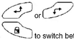 to select the equivalent code from the 32 available user codes.Press between [Y] YES and [N] NO. to select the equivalent code from the 32 available user codes.Press between [Y] YES and [N] NO. |
NOTE:
The switch output is activated by the entry of a user code only if the utility output setting is set to N in the system macros. If quick output is activated, no user code is required.
Output mode
An output mode has to be set for every output. This table gives an overview of the different output modes:
| Outputs | ||
| Quick-Key | Parameter | Default Range |
| 1 | Pulse N/C | 05 seconds 01-90 seconds |
| The output isclosedin non-activated state. Once activated, it remains open until the set time has elapsed and then resets itself automatically. | ||
| 1. Press1followed by#. | ||
| 2. Enter a pulse duration between 1 and 90 seconds. | ||
| 3. Press##and enter the activation of your choice (ALL or ANY). See the note on the next page. | ||
| 4. Press##and select a name for the utility output. | ||
| 2 | Latch N/C | |
| The output isclosedin non-activated state. Once activated, the output remains open until it is reset manually. | ||
| 1. Press2followed by#. | ||
| 2. Press##and enter the activation of your choice (ALL or ANY). See the note on the next page. | ||
| 3. Press##and enter the deactivation of your choice (ALL or ANY). See the note on the next page. | ||
| 4. Press##and select a name for the utility output. | ||
| 3 | Pulse N/O | 05 seconds 01-90 seconds |
| The switch output isopenin non-activated state. Once activated, it remains closed until the set time has elapsed and then resets itself automatically. | ||
| 1. Press3followed by#. | ||
| 2. Enter a pulse duration between 1 and 90 seconds. | ||
| 3. Press##and enter the activation of your choice (ALL or ANY). See the note on the next page. | ||
| 4. Press##and select a name for the utility output. | ||
| 4 | Latch N/O | |
| The switch output isopenin non-activated state. Once activated, the output remains closed and may have to be reset manually. | ||
| 1. Press4followed by#. | ||
| 2. Press##and enter the activation of your choice (ALL or ANY). See the note on the next page. | ||
| 3. Press##and enter the deactivation of your choice (ALL or ANY). See the note on the next page. | ||
| 4. Press##and select a name for the utility output. | ||
Activation/Deactivation
If the switch output follows more than one area or zone, you can use different patterns for activating and deactivating the switch output. ALL or ANY.
All: ALL areas (or zones) programmed for this switch output must be triggered in order to activate the output. On the other hand, all areas or zones must be inactive in order to deactivate the output. The latter applies only to the outputs Latch N/O and Latch N/C. The outputs Pulse N/O and Pulse N/C return to inactive automatically after the period defined by you.
Any: Only ONE area (or zone) programmed for this output has to be triggered in order to activate the output. If one of the areas (or zones) returns to inactive, the output is also deactivated. The latter applies only to the outputs Latch N/O and Latch N/C. The outputs Pulse N/O and Pulse N/C return to inactive automatically after the period defined by you.
Output label
Define a name for each output, for example lighting control or strobe, describing the function of the output.
7.4.2 3 2 Output A
Under Output A/B, you can define the outputs to be activated with the button function [4]/[6] of the ABUS wireless alarm system.
To access the Ausgang A menu:
- Select the Output menu as described on page 7-52.
- In the Output menu, press 2 to access the Output A menu option.
- Enter the two-digit number of the switch output you want to define as output A, and press
7.4.3 3 3 Output B
To access the Output B menu:
- Select the Output menu as described on page 7-52.
- In the Output menu, press 3 to access the Output B menu option.
- Enter the two-digit number of the switch output you want to define as output B, and press
Under Codes, you can define user and installer Codes, define authorities, and assign areas. The ABUS wireless alarm system also has the following Codes.
Grand Master Code: Used by the system owner. This Code has authority over all others and can only be changed but not deleted. The default is: [1][2][3][4].
♦ Installer Code: This Code is needed for programming the system. The default is: [0][1][3][3].
Sub-Installer Code: This Code can also be used for programming the system. However, the options are restricted.
Program the codes as follows:
- Define the authority level of each user code.
- Allocate the areas to a specific code.
- Change the Grand Master Code, the Installer Code and the Sub-Installer Code
- Optionally, you can first extend the security level of a six-digit Code.
The following is an overview of the menu options according to their sequence in the Codes menu:
4 1 Authority, page 7-58
4 2 Partition, page 7-59
4 3 Grand Master, page 7-60
4 4 Installer, page 7-61
4 5 Sub-Installer, page 7-61
4 6 Code Length, page 7-61
To access the Codes menu:
In the installer menu, press 4 or press or until you find the number of the Code [4] menu option. Press . The first submenu appears on the display:

You are now in the Codes menu and can access the submenus, as described in the following sections.
7.5.1 4 1 Authority
Default: User
Under Authority, you can assign an authority to each user PIN. There are 7 authority levels that can be used for customising the requirements of different users.
To access the Authority menu:
- Select the Codes menu as described on page 7-57.
- Under Codes, press 1 to access the Authority menu option. You see the following on the display:
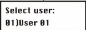
- Press or to select a user and press or enter the two-digit number of the user (from 01 to 31).
- Press to switch between the authorities.
- Press to confirm and continue with the next PIN code.
- Press to exit the menu option.
Authority Levels
The Authority Levels menu option contains settings for the following authorities:
Grand Master: There is only one Grand Master in the system. The Grand Master can carry out all available user functions. The Grand Master code is defined as PIN code user 00.

NOTE:
Under System Control, you can define that the Grand Master can change authorities as well as areas permitted for users. See under Grand Master Authority/Partition (press [1] [2] [27]).
Manager: There is only one Manager in the system. The Manager is defined as Code user 01. The Manager can change all user codes except that of the Grand Master. The Manager has access to all functions listed below, with the following restrictions:
- Changing the Grand Master code
• Performing the walk test
Master: There is no restriction on the number of Masters (as long as they do not exceed the number of codes remaining in the system). The Master has access to all Manager privileges with the following restrictions:
- The Master is restricted to defining and changing user codes at the level of Master or below (user, arm only, maid).
- The Master has restricted access to defined areas.
User: There is no restriction on the number of User PIN codes (as long as they do not exceed the number of PIN codes remaining in the system). A user can:
• Activate/deactivate
- Omit zones
- Access defined areas
• View the state of the system, faults and the alarm memory
• Activate defined switch outputs
- Change his/her own user PIN
- Conduct selected system tests but no walk tests
Arm Only: There is no restriction on the number of Arm Only PIN codes (as long as they do not exceed the number of PIN codes remaining in the system). Users with Arm Only PIN codes only have the authority to activate one or more areas.
Maid: A PIN code with the Maid authority is a temporary user PIN that is deleted by the system immediately after being used for an activation. User PINs with this authority are used as follows:
- For a once-only activation in one or more areas
- The user PIN can be used the first time to deactivate the system and then to activate it.
UO Only: A PIN code with the UO Only authority is used to activate/deactivate a switch output manually.
User Unbypass: A PIN code with the User Unbypass authority has access to all user authorities except omitting zones.
7.5.2 4 2 Partition
Default: Partition 1
Under Partition, you assign to user PINs partitions for which you have authority. The Grand Master is authorised in all partitions.
To access the Partition menu:
- Select the Codes menu as described on page 7-57.
- Under Codes, press 2 to access the Partition menu option.
- Enter the respective two-digit user code and press 📋. You see the following on the display:
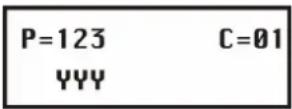
- Press or to place the cursor under the number specifying the partition to which you want to allocate the code.
- Change the authority of the user for the respective partition with buttons 1 to 3. An area authorised for the used is shown with a "Y" under the partition number (1 to 3).

NOTE:
A standard system uses only Partition 1.
- Press to program a different user code.
- Repeat steps 2 to 6 until all user PINs created in the system are allocated to partitions.
- To exit the menu option, press
7.5.3 4 3 Grand Master
Default: 1234
Under Grand Master, you can change the Grand Master PIN.

NOTE:
The Grand Master (only) can also change the code in the user menu.
The Grand Master has most rights. For further information about the rights and options of other users, see under “Authority Levels” on page 7-58.
To access the Grand Master menu:
- Select the Code Maintenance menu as described on page 7-57.
- Under Code Maintenance, press 3 to access the Grand Master menu option. You see the following on the display:
Grand Master 1234
- Enter the new Grand Master PIN on the system keypad and then press
- Press * to exit the menu option.

NOTE:
The Grand Master, the installer and the sub-installer can enter and change PIN codes of other authorities.
7.5.4 4 4 Installer
Default: 0133
With the installer PIN, you have access to the installer menu and thus the authority to change all system parameters. The installer code defined in the factory is: [0][1][3][3]
ABUS strongly recommends changing the PIN defined in the factory.
To access the Installer menu:
-
Select the Code Maintenance menu as described on page 7-57.
-
Under Code Maintenance, press 4 to access the Installer menu option. You see the following on the display:
Installer Code: 0133
- Enter the new Installer PIN on the system keypad and then press

- Confirm the new PIN by repeating the code, and then press

- Press to exit the menu option.
7.5.5 4 5 Sub-Installer
Default: 0233
With the sub-installer PIN, you have restricted access to selected items of the installer menu. Der vom Werk eingestellte Sub-Programmier Pin lautet: [0][2][3][3]
ABUS strongly recommends changing the PIN defined in the factory.
The restrictions on the sub-installer are as follows (the LCD display shows "Disabled" for each restricted menu item):
- System menu: No change of the menu option "Arm/Disarm".
- Pin Code menu: No change of the installer PIN.
- Dialer menu: Can change redial of FM numbers only.
To access the sub-installer menu:
- Select the Code Maintenance menu as described on page 7-57.
- Under Code Maintenance, press 5 to access the Sub-Installer menu option. You see the following on the display:
Sub-Installer
Code: 0233
- Enter the new sub-installer PIN on the system keypad and then press

- Press * to exit the menu option.
Using the sub-installer PIN code
This section describes how the sub-installer gains access to the sub-installer menu.
Using the Sub-Installer code:
- From the user menu, press [9] [2].
- Enter the sub-installer code and press 📄. The sub-installer now has restricted access to the installer menu.
7.5.6 4 6 Code Length
Default: four digits
Under Code Length, you can change the number of digits used (4 or 6) for the Grand Master, the Manager and the Master. All other PIN codes (user, Arm Only and maid) use one to six digits.
To access the Code Length menu:
- Select the Code Maintenance menu as described on page 7-57.
- Under Code Maintenance, press 6 to access the Code Length menu option. You see the following on the display:
Length: 1) 4 digits
- Press to select and then press to confirm your selection. If you change the code length, the following message appears:
Code should be deleted. Sure? N
- Press to change the factory default setting from [N] to [Y] and then press

NOTE:
If you change the Code Length, all user codes are deleted and then have to be redefined or downloaded.
In the case of a six-digit code length, the factory default four-digit codes such as 1-2-3-4 (Grand Master), 0-1-3-3 (installer), and 0-2-3-3 (sub-installer) are changed to 1-2-3-4-0-0, 0-1-3-3-0-0, and 0-2-3-3-0-0.
If you change the Code Length back to four digits, the four-digit codes defined by the factory are restored.
7.6 5 Dialer
The Dialer menu enables you to transmit alarms as voice text by telephone. In this menu, you also make the settings necessary for programming the system via a modem. Some of the options in this menu cannot be selected since they are not active in this version. You can access the following submenus:
To access the Dialer menu:
In the installer menu, press 5 or press or until you find the [5] Dialer menu option. Press #↑. The first submenu appears on the display:
Dialer: 1) Not active
You are now in the Dialer menu and can access the submenus as described in the following sections.
7.6.1 5 4 U/D telephone number
Under U/D telephone number, you can define a telephone number in the system that is dialled for remote servicing of the system by PC.
To access the U/D telephone number menu:
- Select the Dialer menu as described on page 7-63.
-
In the Dialer menu, press 4 and then enter the telephone number for remote servicing with up to 32 digits including local area and other codes.
-
Press
If you do not want to service or program the system via a modem connection, no input is required here.
7.6.2 5 5 U/D Access and ID
Under U/D Access and ID, you can define an access PIN and a user ID for remote servicing of the ABUS wireless alarm system.
To access the U/D Access and ID menu:
- Select the Dialer menu as described on page 7-63.
- In the Dialer menu, press 5 to select U/D Access and ID. You see the following on the display:
U/D Access & ID: 1)Access code
- Select and configure the settings in the U/D Access and ID menu as follows:
| Access Code and ID | ||
| Quick-Key | Parameter | Default |
| 5 5 1 | Access code | 5678 |
| Defines an access code for remote programming. The four-digit access code in the system and the software must be identical. | ||
| 1. Enter a four-digit access code. This code is stored in theABUSwireless alarm system. | ||
| 2. You have to enter the same code in the up/download software for access to this system. | ||
| 3. Press 1 and enter the four-digit code. | ||
| 4. Press #to confirm. | ||
| 5 5 2 | Remote ID Code | 0001 |
| Under this menu option, you can enter a user ID for the corresponding access code. The four-digit ID in the system and the software must be identical. | ||
| 1. Enter a four-digit access code. This code is stored in theABUSwireless alarm system. | ||
| 2. You have to enter the same code in the up/download software for access to this system. | ||
| 3. Press 2 and enter the four-digit code. | ||
| 4. Press #to confirm. | ||
7.6.3 5 6 Controls
Under Controls, you define how telephone alarm transmission is controlled.
To access the Controls menu:
- Select the Dialer menu as described on page 7-63.
- Under Dialer, press 6 to access the Controls menu option. You see the following on the display:
DIALER control: 1) Not active

NOTE:
The menus of this option require you to enter [Y] YES or [N] NO.
-
Make the settings in the Controls menu as described below:
-
Select the menu options with the Quick-Keys or press
✿ Press to switch between [Y] YES and [N] NO and then press to confirm. (Repeat this procedure for each parameter as required.)
✿ Press * to exit the menu option.

Controls
| Quick-Key | Menu | option | Default | ||
| 5 | 6 | 02 | FM Enable | NO | |
| YES: Enables FM (= Follow Me) transmission.(See also Follow Me, page 7-68.)Enable this option to transmit alarms as voice messages by telephone. Disable this option if the system has no telephone connection, since otherwise a telephone error is reported.NO: No FM transmission is possible. | |||||
| 5 | 6 | 03 | U/D Enable | NO | |
| YES: Enables remote dialling of the up/download software by modem.Enable this option if you want to remote-service the system by modem and software. Disable this option if the system has no telephone connection, since otherwise a telephone error is reported.NO: No remote dial-in is possible. | |||||
| 5 | 6 | 05 | Dial Tone | YES | |
| YES: The ABUS wireless alarm system checks before dialling whether a dial tone is available and does not dial until a dial tone is detected. If the system is connected to a PBX, set this option to “No”.NO: The ABUS wireless alarm system dials without waiting for a dial tone. | |||||
| 5 | 6 | 07 | User initiated call | YES | |
| YES: To enable up/download programming, the user has to confirm this every time on the system.NO: Upload/download programming is possible without confirmation by the user. | |||||
| 5 | 6 | 08 | Call Back U/D | YES | |
| YES: The ABUS wireless alarm system calls the programmed U/D callback number when the call is set up. This setting represents extra security.NO: No callback is made. | |||||
| 5 | 6 | 09 | Auto Batch | NO | |
| YES: The ABUS wireless alarm system calls the U/D callback number for an automatic download at a previously defined time. | |||||
NOTE:
To ensure that the Auto Batch setting works:
The U/D computer must be switched on, connected with a telephone line, and have upload/download software.
-AND-
The call must be released.
NO: Auto Download mode is activated.
Controls
| Quick-Key | Menu | option | Default |
| 5 6 10 | Answering Machine Override | YES |
YES: Answering machine override is activated.
• The upload/download software calls the ABUS alarm system.
- The software hangs up following a ring by the U/D user.
- The software calls again within one minute.
- The ABUS wireless alarm system is programmed to answer this second call immediately and not forward the call. The function of the number of calls for U/D is deactivated.
NOTE:
This property is used to prevent problems with a rear-position answering machine or fax machine with remote-controlled upload/download operation.
NO: The ABUS wireless alarm system accepts the call following a specified number of U/D calls.
7.6.4 5 7 Parameters
Under Parameters, you have further options for setting the telephone alarm transmission of your ABUS wireless alarm system.
To access the Parameters menu:
- Select the Dialer menu as described on page 7-63.
- Under Dialer, press 7 to access the Parameters menu option. You see the following on the display:
Dial parameters: 1) Not active
-
Select the menu options in the Parameters menu as in the table below:
-
Select menu options with the keypad or press 📄 or 🙏 to access the corresponding menu option.
- Change the setting accordingly and/or confirm the value already entered by pressing 📄.
- Press to exit the menu.
Dialer: Parameter
| Quick-Key | Parameter | Default | Range |
| 5 7 2 | FM Retries | 03 | 01 to 15 |

Defines the number of repeated call attempts by the alarm system in the event of an alarm.
Rings to U/D 12 01 to 15
Defines the number of ringing tones before the ABUS wireless alarm system accepts the call.
NOTE:
This feature is deactivated if the Answering Machine Override option is enabled (see page 7-66).

Dial Tone Time 6 seconds 6 or 9 seconds
Defines the length of time the ABUS wireless alarm system waits for a dial tone if this is programmed. (See also page 7-65.)
Dialer: Parameter
| Quick-Key | Parameter | Default Range |
| 5 7 4 1 | Wait 6 seconds | |
| Press 1 followed by ♀. | ||
| 5 7 4 2 | Wait 9 seconds | |
| Press 2 followed by ♀. | ||
| 5 7 5 | Redial wait | 30 seconds 30 or 60 seconds |
| The number of seconds between a redial of the same number. | ||
| 5 7 5 1 | Wait 30 seconds | |
| Press 1 followed by ♀. | ||
| 5 7 5 2 | Wait 60 seconds | |
| Press 2 followed by ♀. | ||
| 5 7 6 | Dialing method | DTMF DTMF (Touch Tone ®), pulse 20 BPS and pulse 10 BPS |
| Select DTMF (Dual-Tone Multi-Frequency) as the dial method. Pulse dialling is necessary only for a few older PBXs. | ||
| 5 7 6 1 | DTMF (Touch Tone ®) | |
| Press 1 and then ♀ to activate the DTMF dial method. | ||
| 5 7 6 2 | Impulses @ 20 BPS (pulses per second) | |
| Press 2 and then ♀ to activate the pulse dialling 20 BPS method. | ||
| 5 7 6 3 | Impulses @ 10 BPS (pulses per second) | |
| Press 3 and then ♀ to activate the pulse dialling 10 BPS method. | ||
| 5 7 7 | Pulse Duty Cycle | 61/39% 67/33% and 61/39% |
| Further settings are necessary only for the pulse dialling method. | ||
| 5 7 7 1 | 67/33% | |
| Press 1 and then ♀ for European telephone systems. | ||
| 5 7 7 2 | 61/39% | |
| Press 2 and then ♀ for American telephone systems. | ||
Dialer: Parameter
| Quick-Key | Parameter | Default Range | |||
| 5 | 7 | 8 | Swinger Limit | 00 00 to 15 | |
| The Alarm Limit option is provided to prevent multiple triggering on a zone within the activated time. Setting 01: A triggered zone is not transmitted again if this has already happened. If you raise the limit, the alarm is transmitted according to your setting. | |||||
| NOTE: | |||||
| Enter 00 to disable the alarm abort. Every time the zone triggers, the alarm is transmitted again. | |||||
| 5 | 7 | 9 | Periodic Test | ||
| Defines a time in which the ABUS wireless alarm system calls the UD numbers to test the telephone connection. This feature is possible only if a PC with active software is ready to receive. | |||||
| 5 | 7 | 9 | 2 | UD Test | Hr:00 Min:00 00-24 hours 00-59 minutes |
Under this option, enter the following: The time for the periodic test call (in 24-hour format) and the frequency interval.
To program the test time and the intervals for periodic transmissions:
- Press 2. You see the following on the display:
U/D Test:
Hr=00 Min=00 D:0
- Enter the time in 24-hour format.
- Define the frequency interval (D) according to the table below. The first test call starts on the day of programming.
D Meaning
| 0 | Never |
| H | Hourly |
| M | Monthly |
| 1 | Daily |
| 2 | Every second day |
| 3 | Every third day |
| 4 | Every fourth day |
| 5 | Every fifth day |
| 6 | Every sixth day |
| 7 | Every seventh day |
- Press * to exit the menu option.

More
This menu determines when the system should transmit the reset message. You can select between three possibilities:
1 on BTO (bell time out), 2 follow zone, 3 at disarm
7.6.5 5 9 Follow Me (FM)
Under this menu option, you define the forwarding of an alarm as a voice text to a telephone or a security service. In the event of an alarm, the ABUS wireless alarm system calls the programmed FM numbers and transmits the alarm message according to the event. There are two variants of this FM feature:
- Standard Phone Call: The ABUS wireless alarm system transmits the alarm message as a voice text to programmed numbers, depending on the event. (See also User Functions in the User Guide.)
- Call to Pager: The ABUS wireless alarm system can also send an alarm to a pager. The alarm is transmitted in the form of alphanumeric characters. (See also under Pager in the System Control menu.)
Under this menu option, you define the events for which a call is made.

NOTE:
The FM (= Follow Me) function must be enabled for a call to be made. (See under FM enable, page 7-65). You program the alarm numbers in the user menu. (See under user functions in the user manual.)
To access the FM menu:
- Select the Dialer menu as described on page 7-63.
- Under Dialer, press 9 to access the FM menu option.
- Press or to select the FM number and press to confirm.
| Follow-Me | |||
| Quick-Key | Parameter | Default | |
| 5 9 1 | Events | ||
| Define the events that trigger a call. | |||
| Press or to select an event and press to select whether this event is to be transmitted by phone: [Y] YES or [N] NO. | |||
| [01] | Intruder | Y | |
| [02] | Fire | Y | |
| [03] | Emergency | Y | |
| [04] | Panic | Y | |
| [05] | Tamper | N | |
| [06] | Remote programming | N | |
| [07] | Ac Off N | ||
| [08] | Duress | Y | |
| [09] | Arm | N | |
| [10] | Disarm | N | |
| [11] | Bypass | N | |
| [12] | Wireless Lost N | ||
| [13] | Wireless Low Batt N | ||
| [14] | Bell Trouble N | ||
| [15] | False Code N | ||
| [16] | Low Battery N | ||
| [17] | Wireless Jamming N | ||
| [18] | BUS Trouble | N | |
After defining all alarm events, press 📃 to save your settings. To discard your settings, press *.
Follow-Me
| Quick-Key | Parameter | Default |
| 5 9 2 | Events restore |
Defines whether a new call is made if the event (from section 5.9.1) is reset.


Press ____ or ____ to select an event and press ____ to select whether this event is to be transmitted by phone: [Y] YES or [N] NO.
[01] Intruder Y
[02] Tamper N
[03] AC Off N
[04] Wireless Lost N
[05] Wireless Low Battery N
[06] Bell Trouble N
[07] Low Battery N
[08] Wireless Jamming N
[09] BUS Trouble N
After defining all events, press #↑ to save your settings. To discard your settings, press . *
7.7 7 Key-fobs
Under key-fobs, you learn how to train up to eight 4-button key-fobs with rolling code to work with the ABUS wireless alarm system. With the wireless key-fob/remote control, you can activate/deactivate the system, trigger a panic alarm, and control a switch output. The following is an overview of the menu options according to their sequence in the key-fobs menu:

To access the Key-fob menu:
In the installer menu, press 7 or press or until you find the [7] key pad menu option. Press . You see the following on the display:
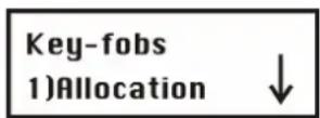
You are now in the Key-fobs menu and can access the submenus as described in the following sections.
7.7.1 7 1 Allocation
Under this menu option, you train the 4-button key-fobs.
To access the Allocation menu:
- Select key-fobs.
- Under key-fobs, press 1 to access the Allocation menu option. You see the following on the display:
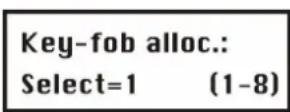
-
On the alarm system, select the number of the remote control you want to train and press
-
To train the remote control:
✿ Press 1 to go to the next remote control.
✿ Press 2 to train a new remote control or overwrite an already trained remote control. Send a training signal (within 255 seconds) from the remote control by pressing the ⚠ (activate) button on the remote control for at least 2 seconds. Every time you press a button, the LED of the remote control lights up. When the ABUS wireless alarm system has successfully trained the remote control, you hear a short beep as confirmation.
✿ Press 3 to delete the selected remote control. Press to select either [Y] or [N] to make your selection, and then press to confirm.
- Repeat steps 2 to 4 to train further remote controls.
7.7.2 7 2 Parameters
Under Parameters, you program the function and the keys of the remote control. The four buttons of the remote control can be adapted to individual requirements.
To access the Parameters menu:
- Select the Key-fob menu as described on page 8-68.
- Under Key-fob, press 2 to access the Parameters menu option. You see the following on the display:

- Select the remote control you want to reprogram and press

Reprogramming a remote control
Every remote control has 4 buttons, and each button can be programmed for a different function.
To change the settings of the remote control:
- Assign to every remote control the areas you want to operate with it. The letter "Y" under the number means that the remote control can operate this area. To change the setting, press 1 or 2 or 3.
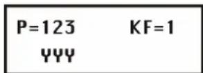
- Press #个 to confirm. You see the following on the display:

-
For button 1 (☐), you can choose between the following functions:
-
None: The button is not activated.
- Arm: The button externally activates all previously selected areas.
- Stay: The button internally activates all previously selected areas.
To select the functions, press or. To confirm, press .
- Now select between whether an exit delay time starts at activation (Delayed) or whether your system is activated immediately (Instant).
- Press . The system goes automatically to the next button and you see the following on the display:
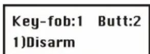
- For button 2 ( ), you can choose between the following functions:
None: The button is not activated (default).
Disarm: The button is used to disarm selected partitions.
-
After selecting an option for the button, press #个. The system automatically goes to the next button.
-
You see the following on the display:
Key-fob:1 Butt:3 2)Panic
- For button 3 (small button), you can choose between the following functions:
None: The button is not activated (default).
- Panic: The button triggers a panic alarm.
◆ Utility Output: The button activates a utility output.
If you select the switch output function and confirm it with ⚪↑, you see the following on the display:
Fob:1 Butt:3 U0:01)Output 01
Select a utility output with or I and confirm your selection with .
- The system changes automatically to the next button and the you see the following on the display:
Key-fob:1 Butt:4 1) Stay
- For button 4 (large button), you can choose between the following functions:
None: The button is not activated (default).
✿ Arm: The button activates all previously selected areas.
❖ Stay: The button internally activates all previously selected areas.
✿ Utility Output: The button activates a utility output. You can then program the utility output as described above.
-
Press to confirm.
-
Repeat the programming steps for all other key fobs.
7.7.3 7 3 Communication Test
Under Communication Test, you can see the signal strength of the remote control.
To access the Communication Test menu:
- Select the Key-fob menu as described on page 7-74.
- Under Key-fob, press 1 to access the Communication test menu option. You see the following on the display:
K-fob comm.test 1) Key-fob 1: -- ↓
-
Press or to select the remote control you want to test.
-
Press a button on the remote control. The display shows the strength of the received signal.
NOTE:
For successful transmission, the signal strength should be higher than the noise level of the receiver. (See also page 7-31.)
Press * to exit the menu option.
Under Keypads, you can assign two operating panels to the ABUS wireless alarm system. The following is an overview of the menu options according to their sequence in the Keypads menu:

To access the Keypads menu:
- In the installer menu, select 8 or press or to access the corresponding menu option.
Press Ⓟ. You see the following on the display:

You are now in the operating panels menu and can access the submenus as described in the following section.
7.8.1 8 1 Allocation
Here you can train a new wireless keypad for your system.
To access the Keypads allocation menu:
- Select the Keypads menu.
- Under Keypads, press 1 to access the Allocation menu option. You see the following on the display:
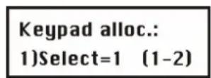
- On the alarm system keypad, select the number of the wireless operating panel you want to train and press

-
The following three menu options are available:
-
Press 1 to train the next wireless keypads.
2 - Press ☐ to train a keypad. Send a learn signal from your wireless keypad by pressing the activation button on the keypad twice. When you press a button, you hear a short beep in confirmation, and the send LED light up briefly.
When your ABUS wireless alarm system has successfully trained the keypad panel, the wireless alarm system confirms this with a short beep. -
Press 3 to delete wireless keypads. Press to select either [Y] or [N], and then press to confirm.
-
Repeat steps 2–4 to train further wireless keypads.
7.8.2 8 2 Communication Test
Under Communication Test you test the radio communication between your wireless operating panel and the system.
To access the Communication test menu:
- Select the Keypads menu as described above.
- Under Keypads, press 2 to access the Communication test menu option. You see the following on the display:
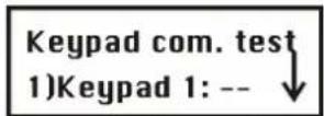
- Press or to select the wireless operating panel you want to test.
- Press the activation button on the wireless operating panel. The display shows the strength of the received signal.
NOTE:
For successful transmission, the signal strength should be higher than the noise level of the receiver. (See also page 7-31.)
Press * to exit the menu option.
7.9 9 Siren
Under Siren, you can assign 3 sounders to the ABUS wireless alarm system. You can choose between internal wireless sounders and external wireless sounders. The following is an overview of the menu options according to their sequence in the Siren menu:

To access the Siren menu:
- In the installer menu, select 9 or press or to access the corresponding menu option. Press You see the following on the display:

You are now in the Siren menu and can access the submenus, as described in the following section.
7.9.1 9 1 Allocation
Here you can allocate a new sounder to your system.
To access the Allocation menu:
-
Select the Siren menu.
-
Under Siren, press 1 to access the Allocation menu option. You see the following on the display:

- Press to select the type of sounder you want to train. Two types are available:
• INWS1: internal wireless sounder
• ODWS1: outdoor wireless sounder
- Select a sounder type and press . You see the following on the display:

- Press to make the following settings for the selected sounder. After each setting, confirm your selection with
• Sound: Set to Y to activate the sounder in the event of an alarm.
- Squawk: If you set this option to Y, the sounder emits an acknowledgement signal when it is successfully activated/deactivated.
- Squawk strobe (external sounders only): If you set this option to Y, the sounder emits a visual acknowledgement signal when it is successfully activated/deactivated.
- After confirming all your settings, you see the following on the display:
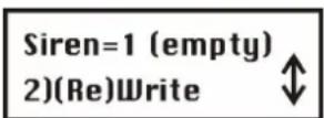
- Confirm the Write menu option with 📄 and your alarm system waits for a signal from your sounder. Send a message from the sounder.
- Insert all batteries in the sounder. Press the Reset key for five seconds. Then press the lid contact of the sounder and keep it pressed until the system receives the signal. You see the following on the display:

- Press or to select whether the sounder is to be monitored or not, and confirm your selection
with . The sounder is now ready for operation.
-
The following menu has four menu options:
-
Skip: Select another sounder.
• (Re) Write: Train another sounder instead of the already sounder. - Delete: Delete a sounder.
• Supervision: Change the setting for monitoring the sounder.
7.9.2 9 2 Parameter
Under this menu option, you can change the sounder settings. You can change the following settings:
Volume
- Flash frequency (external sounders only)
To access the Parameter menu:
-
Select the Siren menu.
-
Under Sirene, press 2 to access the Parameter menu option. You see the following on the display:

-
Press to select the sounder whose settings you want to change and confirm with . You can now choose between the settings for the volume and the flash frequency (external sounders only).
-
Select Volume and confirm with ♦. You see the following on the display:
Siren 01 define 1) Volume
-
You can now set the volume for the following signals:
-
Entry/exit signal
- Alarm signal
-
Acknowledgement signal
-
Confirm with and enter the new volume on the keypad of the system. The setting means:
• 0: Off
• 1: Quiet
• 9: Loud
Enter the volume for the other signals in the same way. You can then set the flash frequency for the external sounder.
Press * to exit the menu option.
7.9.3 9 3 Communication test
Under communication test you test the radio communication between your sounder and the system.
To access the communication test menu:
- Select the Siren menu as described above.
- Under Siren, press 3 to access the communication test menu option. You see the following on the display:
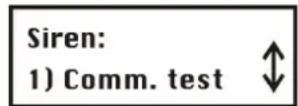
- Confirm with . The system now searches for the wireless sounders and then shows the signal strength of each sounder on the display.
NOTE:
For successful transmission, the signal strength should be higher than the value of the receiver defined under "Calibration" (see below).
Press * to exit the menu option.
7.9.4 9 4 Siren Receiver Calibration
Under siren receiver calibration, you can adjust the reception quality of the sounders. Since this communication is based on a different wireless technology, a different value is possible here than when you calibrate the receiver for the wireless transmitter. The level is between 0 and 99. The lower the value, the better the radio communication between the system and the sounder.
To access the sounder receiver calibration menu:
- Select the Siren menu as described above.
- Under Siren, press 4 to access the siren receiver calibration menu option. You see the following on the display:

-
Confirm with #4. The system now recalibrates the radio threshold.
-
Confirm the new threshold with 5. To make a new calibration, press to change to Y and confirm with
Press to exit the menu option.
7.9.5 9 5 Tamper Mute
Under Tamper Mute, you can deactivate the tamper function of the sounder for the current programming process. This enables you to open the sounder without triggering a tamper alarm. Enable this function if you want to open the sounder case, for example to change the batteries.
To access Tamper Mute menu:
- Select the Siren menu as described above.
- Under Siren, press 5 to access the Tamper Mute menu. You see the following on the display:

- Confirm with . The system now sends a message to all sounders and the tamper function is disabled until you finish programming.
NOTE:
If a tamper alarm has already been triggered, it cannot be stopped by this function. Exit the installer menu and deactivate the system or remove the batteries from the sounders.
- When you exit the installer menu, the tamper function is automatically reactivated on all sounders.
Press * to exit the menu option.
Under Exit Programming, all your settings in the installer menu are saved and you exit the installer menu. Important: The settings you make in the installer menu are not saved until you exit the installer menu correctly.
NOTES:
To be able to exit the installer menu, the J9 jumper plug must be plugged on to one pin.
To access the Exit Programming menu:
- In the installer menu, press 0 or press or until you find the [0] Exit Programming menu option. You see the following on the display:

This is the last option in the installer menu.
Press . You see the following on the display:

- Save or discard all your settings/changes:
Save your changes by pressing . You see the following on the display:

The ABUS wireless alarm system returns to the normal user display.
OR:
Discard your changes by pressing 📄 to change the [Y] YES to a [N] NO on the display and then press 🔊. The ABUS wireless alarm system returns to the normal user display.
Chapter 8 Programming within the user programming menu
This chapter explains an important menu option in the user menu. This menu option is for
programming voice messages and conducting a walk test.
8.1 Programming voice messages
Your ABUS wireless alarm system can issue system events locally and by telephone using voice messages. This greatly simplifies operating the system and enables remote control of the system by telephone. The voice message menu option is in the user menu. Only a user with the Grand Master PIN or an installer PIN has the authority to change voice messages. The voice message menu has the following submenus:
7 1 Message structure, page 8-80
7 2 Voice labeling, page 8-82
7 3 Test message, page 8-87
7 4 Local Announcement Messages, page 8-88
To access the voice message menu:
- Press * to enter the user menu. The press 7 or press or until you see the voice message menu option, and then press #↑.
- Enter the installer PIN or the Grand Master PIN on the keypad and press
- The first submenu appears on the display:

You are now in the voice message menu and can access the submenus as described in the following sections.
Types of voice message
The following three types of voice message can be generated by your ABUS wireless alarm system:
- Event message: In the case of an alarm or an important event, your ABUS wireless alarm system calls the defined FM numbers and transmits the event as a voice text by telephone. This event message consists of four modules that you can define according to your requirements:
General message: a general identification message that tells the listener where the call comes from. The factory setting is: "Hallo, this is your ABUS security system calling."
Event message: an automatically generated alarm-related voice message describing the alarm/event, e.g., "fire alarm".
Area message: if you have divided your wireless alarm system into several areas, the message tells you where the event has occurred, e.g., "residential area".
Zone message: an automatically generated alarm-related voice message used for identifying the zone that triggered the alarm, e.g., "bedroom".
A complete event message can be: "Hallo, this is your ABUS security system calling, fire alarm, residential area, bedroom."
- Status message: The status message gives you an overview of the state of your wireless alarm system – i.e., whether faults exist, which partitions are activated, and which partitions are ready to be activated.
- Local message: Like event messages, your ABUS wireless alarm system also issues messages as voice text over the local loudspeaker.
8.1.1 7 1 Message structure
Under Message structure, you define the sequence in which the voice messages are transmitted.
To define a message structure:
- Select the voice message menu as described above.
- In the voice message menu, press 1 to access the message structure menu option. You see the following on the display:
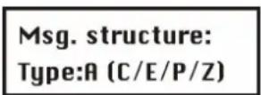
- Press to select one of the following structure types.
[A] (C/E/P/Z) Specifies the sequence of messages as follows: Common, Event, Partition, Zone
[B] (E/P/Z/C) Specifies the sequence of messages as follows: Event, Partition, Zone, Common
8.1.2 7 2 Voice message labels
Under voice message labels, you define names for zones, partitions, utility outputs and macro keys, and you find out how to play and record common messages.
To define a voice message:
-
Select the message label menu.
-
In the voice message menu, press 2 to access the message label menu option. You see the following on the display:
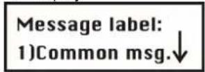
- You can now enter a name for the voice message for each of the following options:
[1] Common message
[2] Zone message
[3] Partition message
[4] Utility output message
[5] Macro message
Press or to select, and confirm with
| Voice message: message name | |||
| Quick-Key | Parameter | Default | Range |
| 7 2 1 | Common message | ||
| Press 1. You see the following on the display: Common message: 1)Play The following options are available: * Press 1 to play the common message. You hear the message over the system loudspeaker. The factory default is "Hello, this is your security system calling" Press 2 to record a new message. You see the following on the display: Press # to start Message record Press #↑ and speak your message into the microphone. The counter on the display counts down the remaining seconds until the recording time expires. Press # to stop rec. Time:2 Recording stops automatically after 10 seconds. If you want to stop recording earlier, press #↑ | |||
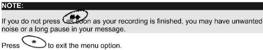
Voice message: message name
| Quick-Key | Parameter | Default | Range |
 | Zone message | ||
Press2. You see the following on the display: 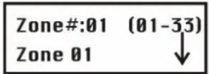 | |||
Pressor to select a zone and then press .  The following options are available:Press1to play the zone announcement. You hear the announcement over the system loudspeaker. The factory default for Zone 1 is “Zone 1”Press2to record a new text. You see the following on the display:Press # to startMessage recordPress#and speak your message into the microphone. The counter on the display counts down the remaining seconds until the recording time expires.Press # to stoprec.Time:2Recording stops automatically after 2 seconds. If you want to stop recording earlier, press#You now have to assign this announcement to a zone.Press3. Pressor to select a zone and then press#You can change the zone name in the installer menu. The recording and the zone name should be identical. The following options are available:Press1to play the zone announcement. You hear the announcement over the system loudspeaker. The factory default for Zone 1 is “Zone 1”Press2to record a new text. You see the following on the display:Press # to startMessage recordPress#and speak your message into the microphone. The counter on the display counts down the remaining seconds until the recording time expires.Press # to stoprec.Time:2Recording stops automatically after 2 seconds. If you want to stop recording earlier, press#You now have to assign this announcement to a zone.Press3. Pressor to select a zone and then press#You can change the zone name in the installer menu. The recording and the zone name should be identical. | |||
Recording stops automatically after 2 seconds. If you want to stop recording earlier, press
- You now have to assign this announcement to a zone.
✿ Press 3. Press or to select a zone and then press
You can change the zone name in the installer menu. The recording and the zone name should be identical.
Message Labels
| Quick-Key | Parameter | Default | Range |
 | Partition Message | ||
| Press 3. You see the following on the display: | |||
 | |||
Press or to select a partition and then press .  The following options are available:Press 1 to play the partition announcement. You hear the announcement over the system loudspeaker.Press 2 to record a new text. You see the following on the display:Press # to startMessage recordPress and speak your message into the microphone. The counter on the display counts down the remaining seconds until the recording time expires.Press # to stoprec. Time:2Recording stops automatically after 2 seconds. If you want to stop recording earlier, pressYou now have to assign this announcement to a zone.Press 3. Press or to select a zone and then press The following options are available:Press 1 to play the partition announcement. You hear the announcement over the system loudspeaker.Press 2 to record a new text. You see the following on the display:Press # to startMessage recordPress and speak your message into the microphone. The counter on the display counts down the remaining seconds until the recording time expires.Press # to stoprec. Time:2Recording stops automatically after 2 seconds. If you want to stop recording earlier, pressYou now have to assign this announcement to a zone.Press 3. Press or to select a zone and then press | |||
Message Labels
| Quick-Key | Parameter | Default | Range |
 | Utility output message | ||
NOTE:The switch output must be defined as an FM code in order to be able to allocate a voice message to it. See also Follow User Code.Press4. You see the following on the display:   a switch output and then press . a switch output and then press .  You see the following on the display: You see the following on the display: The option in the Choose UO menu presents the FM Code switch outputs. Select the number of the appropriate switch output for the message selected in step 3, or select 00 if you do not want to allocate a message to the switch output. The option in the Choose UO menu presents the FM Code switch outputs. Select the number of the appropriate switch output for the message selected in step 3, or select 00 if you do not want to allocate a message to the switch output. | |||
 | Macro Message | ||
Press5. You see the following on the display: Press1449614475144861449614496144961449614496144961449614496144961449614496144961449614496144961449614496144961449614496144 Press1449614475144861449614496144961449614496144961449614496144961449614496144961449614496144961449614496144961449614496144 | |||
| Press14496144751448614496144961449614496144961449614496144961449614496144961449614496144961449614496144 | |||
| Press#to startMessage recordPress#and speak your message into the microphone. The counter on the display counts down the remaining seconds until the recording time expires.Press#to stoprec.Time:2Recording stops automatically after 2 seconds. If you want to stop recording earlier, press# | |||
NOTE:
Macro Message
✿ Press 1 to play the macro announcement. You hear the announcement over the system loudspeaker.
Press 2 to record a new text. You see the following on the display:
Press # to start Message record
Press # to stop rec. Time:2
8.1.3 7 3 Test Message
Under Test Message, you can test recorded and assigned voice announcements.
To conduct a Test message:
- Select the Voice message menu.
- In the Voice message menu, press 3 to access the Test Message menu option. You see the following on the display:

- Conduct the test locally or by telephone as follows:
Voice message: Message test
| Quick-Key | Parameter | Default Range |
| 7 3 1 | Send message | |
| Under this menu option, you can transmit a test message to a previously programmed FM number.To send a test message:1. Press 1. You see the following on the display:Chosse FM:1)FM number 1↓2. Press or to select the FM number to which you want to send the test message. You see the following on the display:Voice FM test activatedThe ABUS alarm system calls the FM number and you hear the following test message: “Test Message”. | ||

Local Play
Under this menu option, you can play voice messages locally over the loudspeaker of your ABUS wireless alarm system.
To play a test message locally:
- Press 2. The voice message "Test Message" is repeated for 90 seconds and the following message appears on the display:
Press any key to stop test
Press any button to stop the playback.
8.1.4 7 4 Local Announcement Messages
Under this menu option, you adapt local voice announcements to your requirements.
To activate/deactivate local voice announcements:
-
Select the Voice Message menu.
-
In the Voice Message menu, press 4 to access the Announce msg. menu option. You see the following on the display:

- Press or to select a local announcement, and activate/deactivated the selected announcement by pressing to select one of the following options:
◆ [N]: To deactivate the local voice announcement.
◆ [Y]: To activate the local voice announcement.
Event Default
| 1) Intruder Y | |
| 2) Fire Y | |
| 3) Emergency Y | |
| 4) Panic Y | |
| 5) Auto Arm Y | |
| 6) Arm Process Y | |
| 7) Arm (Away) Y | |
| 8) Arm (Internal) Y | |
| 9) Disarm | Y |
| 10) Entry delay | Y |
| 11) Menu | Y (Message generated if you use the function keys of the operating panels.) |
| 12) Walk test | Y |
Under the Walk test menu option, you can test your installation. When the system is in walk-test mode, you can trigger detectors without setting off an alarm. The walk test mode can be started in two ways:
- Installer PIN
• Grand Master PIN

NOTE:
The difference between a walk test started with an installer PIN and a walk test started with the Grand Master PIN is the way your ABUS alarm system reacts to a tamper message. If the walk test is started with the installer PIN, there is only a message on the display in the case of a tamper. If the walk test is started with the Grand Master PIN, there is a message and an audible alarm.
To conduct a walk test:
- Make sure that your ABUS wireless alarm system is disarmed
- Press * to access the user menu, followed by 4 to access the Functions menu option.
- You are prompted to enter a user code (PIN). Enter the 4/6-digit Grand Master PIN or the installer PIN and then

- Under Functions, press 2 to access the Walk Test menu option. The system issues the following message "System in Test Mode". You see the following on the display:
Start walk test Done, Hit a key
- Now trigger all detectors you want to test. After a detector has sent its signal and this is received by your system, the system confirms receiving the signal by announcing the zone number and name as a local voice message: e.g. "Zone 3, dining room". In addition, all tested detectors appears in a list on your system display.
- Press ⬆ to exit walk test mode. The system issues the following message: "End of Test Mode"
- Press * to exit the user menu.
Chapter 9 Accessories for your ABUS wireless alarm system
The following is a list of accessories for your ABUS wireless alarm system.
Wireless motion detector
The wireless motion detector is used for protecting entire rooms. With its infrared element, it can monitor an area of 15 × 15m with an angle of vision of 90^ .
Pet-immune wireless motion detector
The pet-immune wireless motion detector, like the normal wireless motion detector, is used for protecting entire rooms. In contrast to the standard model, the pet-immune detector does not trigger an alarm for dogs up to 30kg, cats, and smaller pets.
Wireless water detector
The wireless water detector detects water that has escaped from washing machines and drains and thus prevents even greater damage. The water detector has a 2m cable that allows it to be installed flexibly.
Wireless vibration detector
The wireless vibration detector monitors windows and walls for strong vibrations, caused for example by attempts to lever a window out. It can also protect safes against drilling.
Wireless opening contact detector
The wireless opening contact monitors windows and doors for unauthorised opening. The small, compact design of the magnet allows it to be used almost anywhere.
4-button wireless remote control
The 4-button wireless remote control is used for activating and deactivating your wireless alarm system. The other 2 buttons can be freely programmed, for example to trigger a panic alarm, activate a switch output, or activate the system internally. You can use up to eight 4-button wireless remote controls.
Wireless key pad
The wireless key pad is also used for activating and deactivating your wireless alarm system. You can also trigger panic and fire alarms, and make a medical emergency call. You can use up to two wireless key pads.
Wireless key switch
The wireless key switch is installed externally and is used for activating and deactivating your wireless alarm system with a key.
Internal wireless sounder
The internal wireless sounder alerts the occupants of the house to burglary and fire with a very loud signal. Its very loud tone also causes a high stress potential in the intruder, who then normally abandons the object as fast as possible.
External wireless sounder
The external wireless sounder triggers a loud alarm on burglary or fire and thus alerts the local neighbourhood. It also deters potential burglars in advance. Its strobe light can guide security personnel reliably to the scene of the crime, especially at night.
Chapter 10 Brief guide
This chapter explains the installation steps shown on the DVD for the ABUS wireless alarm package including a smoke detector. After you have taken the installation steps shown in this guide, your ABUS wireless alarm system is completely operational.
10.1 Hardware installation
10.1.1 ABUS wireless alarm system
• Install the ABUS wireless alarm system in a suitable place in your object.
- Plug the power supply unit into the AC socket of the wireless alarm system. Do not plug in the mains plug yet.
- Connect the telephone line with either a RJ11 telephone plug or two loose cables to the telephone connector of the system (Line).
- Place the standby batteries provided in the battery holder and then plug this into the wireless alarm system.
- Plug the jumper plug of jumper J10 on the main board on to both pins to charge the batteries.
- Now plug the power supply unit into the mains socket.
The wireless alarm system starts up and soon reports “System is on”. If not, check that the power supply unit is plugged in, that there is current at the mains socket, and the power supply unit plug is correctly plugged into the wireless alarm system. The fault LED flashes since the time and date have not yet been entered and the batteries are not fully charged. The batteries should be fully charged after 12 hours.
- If the system issues an audible alarm when it is switched on, the tamper contact may not be properly pressed. In this case, do the following:
- Enter the factory default Grand Master PIN on the system keypad: 1 2 3 4
- Press the "Disarm button:
The ABUS wireless alarm system is now ready for programming.
10.1.2 Wireless opening detector
- Install the wireless opening detector at the top centre of the door to be monitored. The magnet is fixed to the movable part of the door. The magnet and the opening detector must be arranged parallel to each other.
- Insert the battery supplied (check polarity!).
The red LED of the detector lights up.
If not, check that the battery is correctly inserted and measure the battery voltage, which must be above 2.8V. - Press in the spring of the detector and close the door.
When you open the door, the LED lights up again.
Wait until the LED switches off, then close the door.
The LED must light up again. If not, the magnet and the transmitter are incorrectly positioned or too far apart.
10.1.3 Wireless motion detector
- Install the wireless motion sensor in the corner of a room with a terrace or balcony. The sensor must point into the room and should not be directed towards large window areas. The red LED of the detector faces up.
IMPORTANT: The infrared detector reacts to heat movement. Therefore, do not point the sensor to fan heaters or other heat sources. Pets such as cats and dogs can also trigger the detector. - Insert the battery supplied (check polarity!).
The red LED of the detector lights up.
If not, check that the battery is correctly inserted and measure the battery voltage, which must be above 2.8V.
10.1.4 Wireless smoke detector
- Install the wireless smoke detector in the centre of your bedroom ceiling. Further smoke detectors should be fitted in the living room and the entrance hall. Smoke always rises first to the highest point of the room.
IMPORTANT: Thick cigarette smoke or water vapour (steam) can trigger the detector. - Insert the two batteries supplied (check polarity!) and press the test button. Keep the button pressed until the smoke detector issues a long beep.
If it does not, remove the batteries and wait 30 seconds. Insert the batteries again and repeat the test.
If it fails again, measure the voltage of both batteries. It must be above 2.8V. - Remove the batteries.
10.2.1 Installer menu of the ABUS wireless alarm system
- First press the star button, followed by 9, followed by 1.
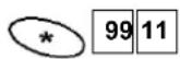
- You are asked to enter the installer PIN code for the installer menu. The default setting is 0133. Enter this installer PIN and confirm your input with the lozenge button.

You are now in the installer menu and see the following display:

10.2.2 Allocate detectors
- Press 2.
You are in the Zones menu option.
- Press 1 followed by 01 followed by # followed by 2. Press # The system waits for a signal from the detector.
- Press the spring of the wireless opening detector and keep it pressed until the system receives the message from the detector (normally within 15 seconds).
The system acknowledges that it has received the signals with a beep.
If not, repeat the procedure.
If the repeated attempt is unsuccessful, you are outside the radio transmission range. Reduce the distance between the system and the detector until the learning process is successful.
- Now press to complete the leaning process for this detector. The system acknowledges this with a long beep.
- To train the next detector, press # followed by 2. Press # The system waits for a signal from the next detector.
- Press the lid contact of the wireless motion sensor and keep it pressed until the system receives the message from the detector (normally within 15 seconds).
The system acknowledges that it has received the signals with a beep. If not, repeat the procedure.
If the repeated attempt is unsuccessful, you are outside the radio transmission range. Reduce the distance between the system and the detector until the learning process is successful.
- Now press to complete the leaning process for this detector. The system acknowledges this with a long beep.
- To train the next detector, press # followed by 2. Press # The system waits for a signal from the next detector.
- Insert the two batteries in the wireless smoke detector and wait until the system receives the learn message from the detector (normally within 15 seconds).
The system acknowledges that it has received the signals with a beep.
If it does not, remove the batteries and wait 30 seconds. The repeat the procedure.
If the repeated attempt is unsuccessful, you are outside the radio transmission range. Reduce the distance between the system and the detector until the learning process is successful.
- Now press #☆ to complete the leaning process for this detector. The system acknowledges this with a long beep.
- Press * twice to complete the learning process. You see the following in the display:
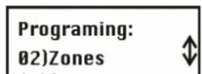
10-92
10.2.3 Programming zones
You do not have to program the zones for the detectors in your package. They are already programmed for you as follows:
| No. Zone name Zone type Detector type Partition Message | |||
| 1 Zone 1 Entry(o)Exit (30sec/30sec) Wireless opening contact detector 1 Entrance door | |||
| 2 Zone 2 Instant Wireless motion sensor 1 Living room | |||
| 3 Zone 3 Fire Wireless smoke detector 1 Bedroom | |||
- With this program, the wireless opening detector starts an entry delay of 30 seconds in which your ABUS wireless alarm system has to be deactivated if it is active. Additionally, you have 30 seconds to leave the object after activating it on the keypad.
- The wireless motion sensor is monitored only if the system is completely active. In an internally activated state, the wireless motion sensor is not monitored so that you can move freely within your object.
• The wireless smoke detector is always active.
If you have bought other detectors, you have to program them now. See the instructions for further information.
10.2.4 Allocate key-fobs
The key-fob has 4 buttons. To allocate the key-fob:
- Press 7. You are in the key-fob menu option.
- Press twice. Press 2 followed by The system waits for a signal from the remote control.
Press the arm key (closed padlock) and keep it pressed until the system receives the message. The system acknowledges this with a long beep.
- Press twice to complete the process. You see the following in the display:

10.2.5 Programming the key fob
You do not have to program the buttons of your remote control. They are already programmed for you as follows:
| Button | Function |
| Active (closed padlock) | Arm |
| Inactive (open padlock) | Disarm |
| Small button | Panic |
| Large button | Internal arm |
If you have bought other remote controls for your package, you have to program them now. See the instructions for further information.
10.3 Enabling voice text transmission by telephone
The telephone transmission function is disabled in the factory since it causes problems if no telephone line is connected. If you want to transmit voice text by telephone, do the following:
- Press 5. You are in the Dialer menu option.
- Press 6 followed by 02. Change the setting from [N] to [Y]. Press once. The display changes to [Y].
- Press #to save your input. - Press *twice to complete the process. You see the following in the display:
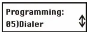
10.4 Exiting the installer menu
All wireless components in the package are now trained. Your ABUS wireless alarm system is almost ready for operation. You just have to enter the date and time and an alarm telephone number for voice text transmission in the event of an alarm. First, exit the installer menu. Proceed as follows:
- Press 0.
The display asks if you want to save your data.
- Press #↑ to confirm.
The ABUS wireless alarm system acknowledges successful saving of data with two long beeps and returns to the normal display:

10.5 Programming date and time
Enter the date and time as follows:
- First press the star button followed by 6.

- You are asked to enter the Grand Master PIN code for the user menu. The default setting is 1234. Enter this Grand Master PIN and confirm your input with the lozenge button.

You are now in the Clocks user menu and see the following display:
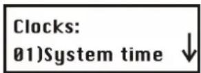
- Press 静合 and enter the current time in 24-hour format with 4 digits. For example 1111.
- If you make a mistake, press the star button followed by the Enter button.
- Press ⬆ to store the time.
- Press the button 2 and enter the current date. To change the month use the button.
- Press ⬆ to store the date.
- Press * to exit the user menu.
10.6 Programming the FM (follow me) number
You enter the Follow Me number – i.e., the number to be called in the event of an alarm – in the user menu. You can enter the FM number only if this function is first enabled in the installer menu (see 11.3).
- First press the star button, followed by 2, followed by 2.

- Confirm the Define menu item by pressing
- You are asked to enter the Grand Master PIN code for the user menu. The default setting is 1234. Enter this Grand Master PIN and confirm your input with the lozenge button.

You are now in the FM user menu and see the following display:

- Confirm the menu option phone number 1 with the Enter button.

- On the system keypad, enter the number with local area code and if necessary a zero for obtaining a dial tone. To program a dial pause, enter A. You program the A with the button. Press this button repeatedly until an A appears.
- To change the entered number, press the cursor buttons and to position the cursor under the number you want to change.
- To delete the entire number, program an E with the button at the first digit of the number and then save the entered number with the #▲ button. The number is deleted and does not appear again when this menu option is displayed.
- After successfully entering the number, press 📄 to store the number. Enable the function Remote program and Remote listen to operate your system by telephone and listen in to the object over the loudspeaker. Press 🔒 to change the settings to Y and confirm your input with 📄. Press ✕ several times to exit the user menu.
10.7 Triggering a test alarm
Activate your system with the remote control or press the 📄 activate button on your system. Following expiry of the exit delay time (30 seconds), your system is active and monitoring all detectors. Now open the contact detector. The entry delay time (30 seconds) starts. The system signals this by means of signal tones at one-second intervals.
To deactivate the system, enter the Grand Master PIN 1 2 3 4, followed by the deactivate button (open padlock).
Close the door and reactivate your system. Wait until the exit delay time expires and then open the contact detector again. Do not deactivate your system, but wait until the entry delay time expires. After the end of the delay time, an alarm is triggered.
After a short time, you receive a call from to the programmed telephone number. Now deactivate your system and confirm the call on your telephone. For more information, see the brief guide on telephone control.
10.8 Changing the Grand Master PIN
Now that your system is operational, change the Grand Master PIN.
- First press the star button followed by 5.

- You are asked to enter the Grand Master PIN code for the user menu. The default setting is 1234. Enter this Grand Master PIN and confirm your input with the lozenge button.

You are now in the FM user menu and see the following display:

- Press the Enter button three times keypad. and enter the new four-digit Grand Master (SUPER) PIN on the
- Confirm your input by pressing . If you forget your Grand Master PIN, you can change it in the installer menu.
- Press * several times to exit the user menu.
Chapter 11 Example of an installation plan
The following table provides an overview of the information your installation plan should contain:
| Partition | Zone number | Detector | Zone type | Name |
| 1 | 1 Door and window contacts Entry/exit MC front door | |||
| 1 | 2 Door and window contacts Entry/exit MC terrace door | |||
| 1 | 3 Motion detector Instant MS living room | |||
| 1 | 4 Motion detector Instant MS entrance hall | |||
| 1 | 5 Smoke detector Fire SD living room | |||
| 1 | 6 Smoke detector Fire SD bedroom | |||
| 1 | 7 Smoke detector Fire SD hall | |||
| 1 | 8 Key-switch Key switch latched KS front door | |||
| Partition | Zone number | Detector Zone type | Name | |
| 1 | ||||
| 2 | ||||
| 3 | ||||
| 4 | ||||
| 5 | ||||
| 6 | ||||
| 7 | ||||
| 8 | ||||
| 9 | ||||
| 10 | ||||
| 11 | ||||
| 12 | ||||
| 13 | ||||
| 14 | ||||
| 15 | ||||
| 16 | ||||
| 17 | ||||
| 18 | ||||
| 19 | ||||
| 20 | ||||
| 21 | ||||
| 22 | ||||
| 23 | ||||
| 24 | ||||
| 25 | ||||
| 26 | ||||
| 27 | ||||
| 28 | ||||
| 29 | ||||
| 30 | ||||
| 31 | ||||
| 32 | ||||
| 33 | ||||
Appendix A: Event Log Messages
This appendix provides descriptions of all the Event Log messages(ver 1.2xx)
EVENT MESSAGE DESCRIPTION
Activate UO=X UO XX activation
Actv UO=XX WB=YY UO XX is activated from key-fob YY
Alarm Z=XXX Alarm in zone No. XXX
Alarm abort P=X Alarm aborted on Partition X
Arm:P=X WB=YY Partition X armed by wireless key-fob YY
Arm:P=X C=YY Partition X armed by user YY
Bell tamper Bell tamper alarm
Bell Tamper rst Bell tamper alarm restore
Box tamper Box tamper alarm
Box Tamper rst Box tamper alarm restore
Bypass Z=XXX Zone No. XXX is bypassed
Chang code=XX Changing user code by user XX
Chang phone=X Changing MS telephone number X
Clock not set Time is not set
Clock set C=XX Time defined by user No. XX
Comm ok UO=X Bus communication restore with X10 expander ID=X
CP reset The system has reset
Date set C=XX Date defined by user No. XX
Day arm:P=X Daily Arm on Partition X
Day disarm:P=X Daily Disarm on Partition X
Day home: P=X Daily Stay (Home) Arming in Partition X
Disarm:P=X WB=YY Partition X disarmed by wireless key-fob YY
Disarm:P=X C=YY Partition X disarmed by user YY
Duress C=XX Duress alarm from user No. XX
EE ac.upload Load new parameters from PTM accessory
Enter program Entering Installer programming from keypad or UD software
Exit program Exiting Installer programming from keypad or UD software
F.tr ok Z=XXX Trouble restore in Fire zone No. XXX
F.trouble Z=XXX Trouble in Fire zone No. XXX
False code False code due to 3 wrong attempts
Fire KP=XX Fire alarm from wireless keypad XX (keys 3 & 4)
Fire main KP Fire alarm from the WisDom fire emergency keys
Fire Z=XXX Fire alarm in zone No. XXX
Foil ok Z=XXX Restore in foil (Day) zone No. XXX
EVENT MESSAGE DESCRIPTION
Foil Z=XXX Trouble in foil (Day) zone No. XXX
Forced P=X Partition X is force armed
Found Z=XXX Wireless zone found, zone No. XXX
Func=XX C=YY Quick key function XX by user YY
Home:P=X C=YY Partition X is armed in Stay(Home) mode by user YY
Home:P=X WB=YY Partition X is armed in Stay(Home) from key-fob YY
Jamming restore Wireless jamming restore
Ksw arm:P=X Partition X is armed by keyswitch
Ksw disarm:P=X Partition X is disarmed by keyswitch
L.bat rstr WB=XX Low battery trouble restore from wireless key-fob XX
LB rstr Z=XXX Low battery restore from wireless zone No. XXX
Lost Z=XXX Wireless zone lost, zone No. XXX
Low bat. WB=XX Low battery trouble from wireless key-fob XX
Low bat Z=XXX Low battery trouble from wireless zone No. XXX
Main: bell rs Bell trouble restore
Main:AC Restore AC power restore to the system
Main:low AC Loss of AC power from the system
Main:Low battery System low battery trouble from the WisDom
Main:no aux Failure in the system's Aux power
Main:no bell Bell trouble
MS=X call error Communication fail trouble to MS phone No. X
MS=X restore Communication fail trouble restore to MS phone No. X
Next arm: P=X Partition X armed in Next Arm(Away) mode
Next disarm:P=X Partition X disarmed in Next Disarm mode
Next home: P=X Partition X armed in Next Stay(Home) mode
No comm UO=X Communication failure with X10 expander ID=X
Phone restore Phone line trouble restore
Phone fail If the phone line is cut or the DC level is under 3V
Police KP=XX Police (panic) alarm from wireless keypad XX (keys 1 & 2)
Police main KP Police (panic) alarm from the WisDom keys
Police WB=XX Police (panic) alarm from key-fob XX
RF Jamming Wireless system jamming
Remote home: P=X Partition X armed in Stay(Home) mode from the UD software
Remote program The system has been programmed from the UD software
EVENT MESSAGE DESCRIPTION
Restore Z=XXX Alarm restore in zone No. XXX
Remote arm:P=X Partition X armed from the UD software
Rmt disarm:P=X Partition X disarmed from the UD software
Spec. KP=XX Special alarm from wireless keypad XX (keys 7 & 8)
Spec. main KP Special alarm from the WisDom emergency keys
Soak fail Z=XXX Zone XXX has failed in the Soak test
Start exit P=X Exit time started in partition X
Tamper KP=XX Tamper alarm from keypad ID=XX
Tamper UO=X Tamper alarm from X10 expander ID=X
Tamper Z=XXX Tamper alarm from zone No. XXX
Tamper rst KP=XX Keypad XX tamper restore
Tamper rst UO=X Tamper alarm restore from X10 expander ID=X
Tamper rs Z=XXX Tamper alarm restore on zone No. XXX
Unbypass Z=XXX Zone No. XXX is unbypassed
- ABUS WIRELESS ALARM SYSTEM
- 0
- INSTALLATION INSTRUCTION
- Contents
- Chapter 1 Usage in accordance with regulations
- Chapter 2 Safety information
- Chapter 3 Introduction to the ABUS wireless alarm system
- FOR BRIEF INSTRUCTIONS OF STARTING UP THE ABUS WIRELESS ALARM PACKAGE, SEE PAGE 11-88.
- Scope of delivery
- What is the ABUS wireless alarm system?
- What are the functions of the ABUS wireless alarm system?
- What are the technical specifications of the ABUS wireless alarm system?
- How can the ABUS wireless alarm system be extended?
- security center
- Chapter 4 Initial considerations
- What kinds of security are there?
- Smoke detectors save lives!
- What wireless detectors do I need?
- Where do I install the ABUS wireless alarm system?
- What is the best installation sequence?
- Chapter 5 Installing the ABUS wireless alarm system
- What is what inside the ABUS wireless alarm system?
- How do I install the ABUS wireless alarm system?
- Preparing the base plate
- Assembling the base plate
- Fixing the faceplate
- How do I install the power and telephone connections?
- How do I adjust the contrast of the LCD display?
- Connecting a wired sounder
- To connect an external sounder:
- WARNING:
- NOTE:
- Sounder tamper
- Controllable relay and transistor outputs
- Connecting a device ground
- Connecting to ground:
- IMPORTANT NOTE:
- Connecting a wired zone
- Connecting an external consumer
- IMPORTANT:
- NOTES:
- How are the standby batteries used?
- CAUTION:
- Inserting the batteries:
- Chapter 6 Programming the ABUS wireless alarm system
- Chapter 7 Settings in installer menu
- Introduction to installer menu
- 1 System
- To access the System menu option:
- 1 1 Timers
- To access the Timers menu option:
- 1 2 System Control
- To access the System Control menu option:
- 1 3 Receiver
- To access the Receivers menu option:
- 1 4 Set Clock
- To access the Set Clock menu:
- To enter a new name:
- To access the System Label menu:
- To assign the label "Buero" to partition 1:
- 1 6 Tamper Sound
- To access the Tamper Sound menu:
- 1 7 System Default Jumper
- To access the Default Jumper menu:
- 1 8 Service Information
- To access the Service Information menu:
- 1 9 Version
- To access the Version menu:
- 2 Zones
- To access the Zones menu:
- 2 1 Allocation
- To access the Allocation menu:
- 2 2 Parameters
- Parameter
- Quick-Key
- Default Range
- IMPORTANT INFORMATION:
- Zone 33 (wired zone)
- Zone termination
- Zone loop response
- Zone Label
- Zone Partition
- Partitions 1–3
- 2 4
- Zone Type
- Zone Sound
- Force Arm
- 2 3 Zone Testing
- To access the Testing menu:
- Wireless Communication Test
- 3 2
- Soak Test
- 2 4 Editing
- To access the Editing menu:
- 2 5 Cross Zone
- To access the Cross Zone menu:
- 3 Outputs
- To access the Outputs menu:
- 3 1 Define
- To access the Define menu:
- Output mode
- Activation/Deactivation
- Output label
- 3 2 Output A
- To access the Ausgang A menu:
- 3 3 Output B
- To access the Output B menu:
- 4 1 Authority
- Authority Levels
- 4 2 Partition
- Default: Partition 1
- To access the Partition menu:
- 4 3 Grand Master
- Default: 1234
- To access the Grand Master menu:
- 4 4 Installer
- Default: 0133
- To access the Installer menu:
- 4 5 Sub-Installer
- Default: 0233
- To access the sub-installer menu:
- Using the sub-installer PIN code
- Using the Sub-Installer code:
- 4 6 Code Length
- Default: four digits
- To access the Code Length menu:
- 5 Dialer
- To access the Dialer menu:
- 5 4 U/D telephone number
- To access the U/D telephone number menu:
- 5 5 U/D Access and ID
- To access the U/D Access and ID menu:
- 5 6 Controls
- To access the Controls menu:
- 5 7 Parameters
- To access the Parameters menu:
- More
- 5 9 Follow Me (FM)
- To access the FM menu:
- 7 Key-fobs
- To access the Key-fob menu:
- 7 1 Allocation
- 7 2 Parameters
- Reprogramming a remote control
- To change the settings of the remote control:
- 7 3 Communication Test
- To access the Communication Test menu:
- To access the Keypads menu:
- 8 1 Allocation
- To access the Keypads allocation menu:
- 8 2 Communication Test
- 9 Siren
- To access the Siren menu:
- 9 1 Allocation
- 9 2 Parameter
- To access the Parameter menu:
- 9 3 Communication test
- 9 4 Siren Receiver Calibration
- To access the sounder receiver calibration menu:
- 9 5 Tamper Mute
- To access Tamper Mute menu:
- To access the Exit Programming menu:
- Chapter 8 Programming within the user programming menu
- Programming voice messages
- To access the voice message menu:
- Types of voice message
- 7 1 Message structure
- To define a message structure:
- 7 2 Voice message labels
- To define a voice message:
- Message Labels
- Macro Message
- Press # to start Message record
- Press # to stop rec. Time:2
- 7 3 Test Message
- To conduct a Test message:
- Local Play
- 7 4 Local Announcement Messages
- To activate/deactivate local voice announcements:
- To conduct a walk test:
- Chapter 9 Accessories for your ABUS wireless alarm system
- Wireless motion detector
- Pet-immune wireless motion detector
- Wireless water detector
- Wireless vibration detector
- Wireless opening contact detector
- 4-button wireless remote control
- Wireless key pad
- Wireless key switch
- Internal wireless sounder
- External wireless sounder
- Chapter 10 Brief guide
- Hardware installation
- ABUS wireless alarm system
- Wireless opening detector
- Wireless motion detector
- Wireless smoke detector
- Installer menu of the ABUS wireless alarm system
- Allocate detectors
- Programming zones
- Allocate key-fobs
- Programming the key fob
- Enabling voice text transmission by telephone
- Exiting the installer menu
- Programming date and time
- Programming the FM (follow me) number
- Triggering a test alarm
- Changing the Grand Master PIN
- Chapter 11 Example of an installation plan
- Appendix A: Event Log Messages
- EVENT MESSAGE DESCRIPTION
Brand : ABUS
Model : FU9001
Category : Secure Access Control System