
Z82 - Card printer ZEBRA - Free user manual and instructions
Find the device manual for free Z82 ZEBRA in PDF.


| Product Type | ID Card Printer |
| Brand | Zebra |
| Model | Z82 |
| Print Method | Direct-to-card (DTC) |
| Resolution | 300 dpi (300 x 300) |
| Print Speed | Up to 200 cards/hour (single-sided, color) |
| Print Sides | Single-sided (optional dual-sided with flip station) |
| Card Types | PVC, composite, polyester (0.51-0.76 mm thickness) |
| Card Size | CR-80 (54 x 86 mm), ISO standard |
| Input Hopper Capacity | 100 cards (autofeed) |
| Output Hopper Capacity | 30 cards |
| Connectivity | USB 2.0, Ethernet (optional) |
| Display | 2-line LCD with backlight |
| Dimensions (W x D x H) | 206 x 368 x 224 mm (8.1 x 14.5 x 8.8 in) |
| Weight | 5.4 kg (11.9 lbs) |
| Power Supply | 100-240 VAC, 50/60 Hz (external power adapter) |
| Power Consumption | 230 W typical (standby: 30 W) |
| Operating Temperature | 15°C to 35°C (59°F to 95°F) |
| Humidity | 20% to 80% non-condensing |
| Supported Software | Zebra CardStudio, Windows drivers |
| Cleaning | Use Zebra cleaning kit; clean printhead and rollers monthly |
| Safety Certifications | FCC, CE, UL, RoHS |
| Repair and Parts | Replacement printhead, rollers, power supply available |
| Warranty | 1 year limited warranty |
Frequently Asked Questions - Z82 ZEBRA
User questions about Z82 ZEBRA
0 question about this device. Answer the ones you know or ask your own.
Ask a new question about this device
Download the instructions for your Card printer in PDF format for free! Find your manual Z82 - ZEBRA and take your electronic device back in hand. On this page are published all the documents necessary for the use of your device. Z82 by ZEBRA.
USER MANUAL Z82 ZEBRA
natural_image
Abstract black and white geometric pattern with curved white lines on a black background (no text or symbols)P1011091-001 Rev. B

natural_image
Line drawing of a mechanical device with control panel and buttons (no text or symbols)Zebra® ZXP Series 8™ Card Printer
User's Manual
Copyright Notice
© 2010 ZIH Corp.
This document contains information proprietary to Zebra Technologies Corporation. This document and the information contained within is Copyrighted by Zebra Technologies Corporation and may not be duplicated in full or in part by any person without written approval from Zebra.
While every effort has been made to keep the information contained within current and accurate as of the date of publication, no guarantee is given that the document is error-free or that it is accurate with regard to any specification. Zebra Technologies Corporation reserves the right to make changes, for the purpose of product improvement, at any time.
Trademarks
ZXP Series 8 is a trademark and Zebra is a registered trademark of Zebra Technologies Corporation. Windows is a registered trademark of Microsoft Corporation in the United States and other countries. All other trademarks or registered trademarks are marks of their respective holders.
Product Disposal

Product Disposal Information • Do not dispose of this product in unsorted municipal waste. This product is recyclable, and should be recycled according to your local standards. For more information, please see our web site at: http://www.zebra.com/environment
Contents

natural_image
Abstract black and white pattern with curved white lines on black background (no text or symbols)1 • Introduction. 1
Components 2
Controls, Connectors, and Indicators 4
Icons 5
Zebra Supplies 5
2 · Installation and Setup. 7
General Information....7
Unpacking the Printer 8
Installing the Card Hoppers....10
Loading Cards....11
Opening the Printer Door 12
Installing the Card Cleaning Cartridge 13
Installing the Card Cleaning Roller 14
Loading the Transfer Film 15
Loading a Print Ribbon 17
Connecting Power....19
Connecting the Printer to your Computer 20
Installing the Windows Printer Driver 22
3·Operation. 35
Introduction 35
Card Type Selection 36
Printing a Sample Card....37
Manual Card Feed....38
Operator Control Panel (OCP) 40
Ethernet Indicators -- Detail. 49
Contents
4 • Printer Settings and Adjustments .... 51
Introduction 51
Properties 52
Printing Preferences....60
5 • ZXP Series Toolbox.... 71
Introduction 71
ZXP Series Toolbox Access 72
Information 73
Configuration....76
Cleaning 83
Print Test Card....85
Technology 86
Advanced Security 88
Print Viewer....91
6 • Cleaning. 93
Cleaning the Printer....93
Cleaning the Printhead 97
Card Cleaning Cartridge 98
Card Cleaning Roller....98
7 • Troubleshooting ..... 99
OCP Error Messages 100
OCP Test Card Images 107
Test Card Descriptions 108
Ethernet Issues 109
8 • Technical Specifications .....111
Standard Features....111
Specifications 112
Declarations of Conformity 115
Appendix A • Printer Configurations .....117
Appendix B • Setting Custom Card Specifications. .....119
Appendix C • Network Operations ..... 161
Appendix D • Magnetic Card Encoder ..... 171
Appendix E • Smart Card Options 179
Appendix F • Packing the Printer for Shipment. 185
Appendix G • Worldwide Support. 187
This manual contains installation and operation information for the Zebra ZXP Series 8 Card Printers manufactured by Zebra Technologies Corporation.

natural_image
Line drawing of a mechanical device with ports and control panel (no text or symbols)The Zebra ZXP Series 8 Card Printers use reverse transfer printing technology to create photo-quality and over-the-edge images on plastic identification cards.
Zebra's reverse transfer printers provide fast throughput and a range of encoding options for a variety of markets and applications.
Components
Front View, Covers Closed

Front View, Printer Cover Open
The following figure shows components of the printer.


Introduction
Controls, Connectors, and Indicators
Controls, Connectors, and Indicators
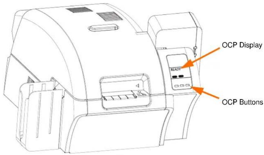
Your printer has an OCP Display and three OCP Buttons on the front and a power connector, power switch, and interface connector(s) on the rear panel.

Icons
Throughout this manual, different icons highlight important information, as follows:

Note • Indicates information that emphasizes or supplements important points of the main text.

Important • Advises you of information that is essential to complete a task, or points out the importance of specific information in the text.

Provides an example or scenario to demonstrate or clarify a section of text.

Electrostatic Discharge Caution • Warns you of the potential for electrostatic discharge.

Electric Shock Caution • Warns you of a potential electric shock situation.

Hot Surface • Warns you of a situation where excessive heat could cause a burn.

Caution • Advises you that failure to take or avoid a specific action could result in physical harm to you, or could result in physical damage to the hardware.
Zebra Supplies
Genuine Zebra supplies meet stringent quality standards and are recommended for optimal printing quality and proper printer performance. The ZXP Series 8 printer is designed to work only with Zebra True Colours® i Series™ Ribbons and True Colours™ i Series™ Transfer Film.

natural_image
Line drawing of a mechanical device with no visible text or symbols2
Installation and Setup

natural_image
Abstract black and white pattern with curved white lines on black background (no text or symbols)General Information
This section will guide you through the installation and setup of your Card Printer. This consists of the following procedures, which should be performed in the order presented.
- Unpacking the Printer....8
• Installing the Card Hoppers ..... 10 - Loading Cards ...... 11
- Opening the Printer Door....12
• Installing the Card Cleaning Cartridge. 13
• Installing the Card Cleaning Roller ..... 14 - Loading the Transfer Film 15
- Loading a Print Ribbon 17
- Connecting Power .... 19
- Connecting the Printer to your Computer 20
• Installing the Windows Printer Driver 22
The procedure to be followed for Packing the Printer for Shipment is given at the end of this section.
Unpacking the Printer
Step 1. Inspect the shipping container to ensure that no damage has occurred during shipment. If any damage is apparent, file a claim with the shipper.
Step 2. Open the shipping container.
Step 3. Remove the packing material and accessories.

Important • Save all the packing material and the shipping carton in case the Printer needs to be moved or shipped. If the original material is lost or damaged, a replacement Shipping Kit can be ordered from Zebra.
Step 4. Make sure the following items are included with your Printer:
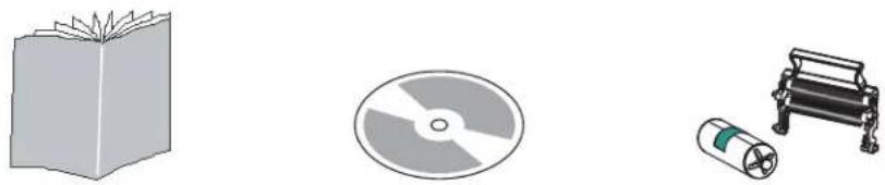
natural_image
Illustration of three electronic components: a closed book, a circular disc, and a cylindrical battery (no text or symbols)Quick Start Guide CD-ROM with InstallWizard Cleaning Cartridge
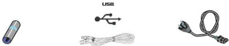
natural_image
Illustration of three electronic components: a cylindrical battery, a USB plug, and a cord with connectors (no text or symbols)Cleaning Roller USB Cable Power Cable

natural_image
Three technical line drawings of mechanical components or enclosures, no text or symbols present.Cleaning Kit Input Hopper Output Hopper
If any items are missing, please contact your dealer. To reorder, please refer to Appendix G of this manual.

Caution • The Printer weighs approximately 27.5 lbs (12.5 kg).
Step 5. Lift the Printer out of the carton by holding it with both hands.
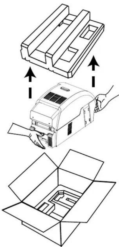
natural_image
Technical illustration showing a mechanical assembly with arrows indicating process flow (no text or symbols present)Step 6. Place the Printer in a location that meets the following requirements:
- A reasonably dust- and dirt-free environment.
- Flat surface at least 27 in (686 mm) x 28 in (711 mm) that can support the weight of the Printer; additional space preferred. Allow a 4-inch clearance, minimum, on all sides.
• Vertical clearance at least 32 in (813 mm).
• Temperature within the range of 59^ to 77^ F ( 15^ to 25^ C). - Relative Humidity 20 to 80% inclusive, non-condensing.
- AC power accessible.
Step 7. Remove the protective plastic bag from the Printer.
Installing the Card Hoppers
Input Hopper
The Input Hopper is positioned on the right side of the Printer and holds the cards to be printed.
Step 1. Install the Input Hopper by sliding the hopper into the receptacle on the right side of the Printer.
Step 2. Ensure that the Input Hopper locks securely in place.

natural_image
Technical line drawing of a mechanical device with internal components and assembly steps (no text or symbols)Output Hopper
The Output Hopper is positioned on the left side of the Printer and receives the printed cards.
Step 1. Install the Output Hopper by inserting the four tabs on the right side of the hopper into the four slots on the left side of the Printer.
Step 2. Ensure that the Output Hopper locks securely in place.
Loading Cards

Caution • DO NOT bend cards or touch print surfaces as this can reduce print quality. The surface of the cards must remain clean and dust free. Always store cards in an enclosed container. Ideally, use cards as soon as possible.
Step 1. Remove the wrapping from the card deck.
Step 2. Holding the card deck by the sides (do not touch the print surfaces), hold it vertically against a flat surface such as a desktop. If the deck is too thick for your hand to hold it comfortably, use about half a deck at a time.

natural_image
Hand holding a rectangular object with a downward arrow, no text or symbols present
Step 3. Push the stack back and forth to an angle of about 45^ from vertical, so as to separate all of the cards.

Note • Static charges and edge burrs from the card die-cutting process can render individual cards stuck together with significant adhesion force. These cards must be physically separated from each other before inserting into the feeder; if not separated, feeding or printing problems may occur.
Step 4. Restore the card stack to its original squared-off condition.
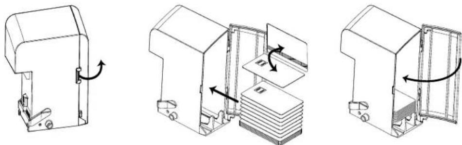
Step 5. Open the Input Hopper Door.
natural_image
Three technical line drawings of a refrigerator interior showing door, shelf, and door frame assembly (no text or symbols)Step 6. Place the cards in the Input Hopper in the orientation as shown (smartcard contacts, if present, up and toward the body of the printer; mag stripe, if present, down and to the rear). Ensure that the cards are seated flat on the bottom of the hopper.
Step 7. Close the Input Hopper Door.
Opening the Printer Door
Step 1. Press the Door Release button on the top of the Printer.
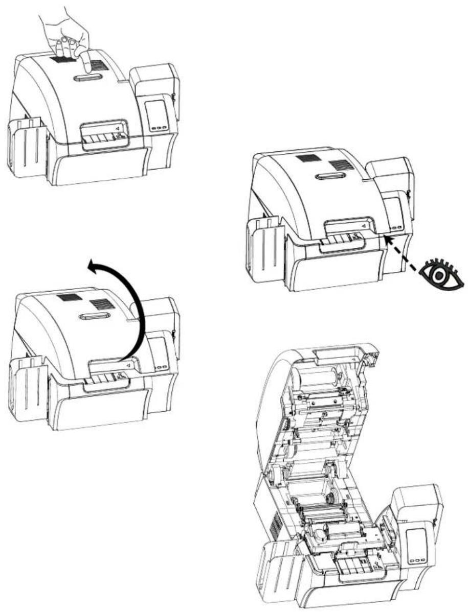
Step 2. Observe that the Door releases and pops up approximately half an inch.
Step 3. Grasp the Door at the bottom front.
Step 4. Lift the Door to its upright position. It will remain in that position.
Installing the Card Cleaning Cartridge
The Card Cleaning Cartridge cleans the cards entering the Printer from the Input Hopper. The Card Cleaning Cartridge consists of a Cartridge Frame and an Adhesive Roller, which are packed together.
Step 1. Remove the Cartridge Frame and the Adhesive Roller from their packaging.
Step 2. Insert the Adhesive Roller into the Cartridge Frame. To avoid contamination, always hold the frame and the roller by the ends.
Step 3. Peel the protective wrapper from the Adhesive Roller.
Step 4. Open the Printer Door by pressing the Door Release button on the top of the Printer.
Step 5. Locate the area where the Card Cleaning Cartridge will be installed (adjacent to the Input Hopper); circled below.
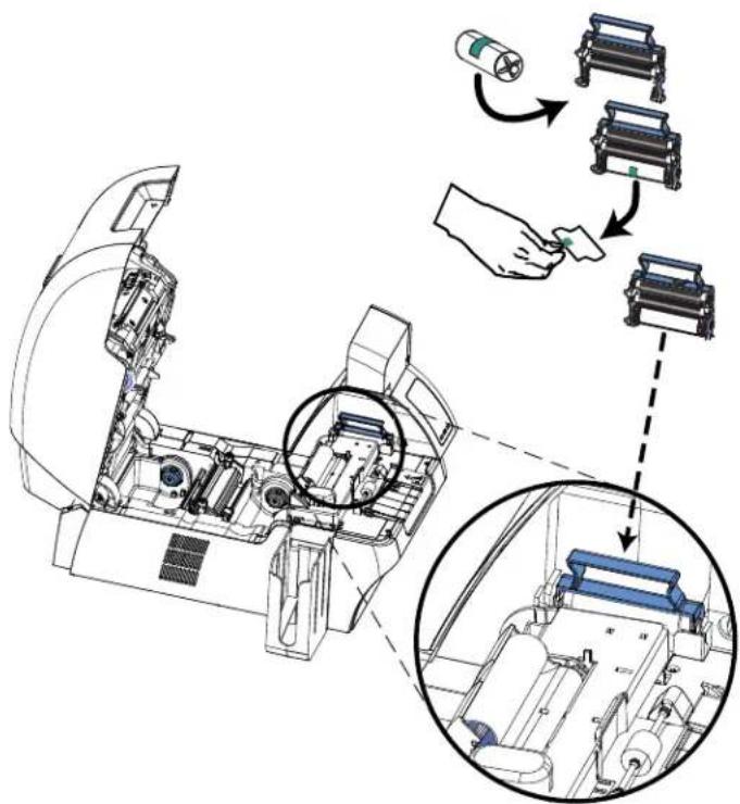
Step 6. Hold the Card Cleaning Cartridge by the extended handle.
Step 7. With the cartridge at about a 30 ° angle (pointing downward), insert the lip of the cartridge into the slot, until the cartridge seats against the back wall.
Step 8. Press the front of the cartridge down until it seats all the way down and latches.
Step 9. Close the Printer's Door.
Installing the Card Cleaning Roller
The Card Cleaning Roller cleans the cards entering the Printer from either the Input Hopper or the Single-Feed Input.
Step 1. Remove the Card Cleaning Roller from its packaging. To avoid contamination, always hold the roller by the ends.
Step 2. Peel the protective wrapper from the Card Cleaning Roller.
Step 3. Open the Printer Door by pressing the Door Release button on the top of the Printer.
Step 4. Locate the area where the Card Cleaning Roller will be installed; circled below.

Step 5. Hold the Card Cleaning Roller by the ends.
Step 6. Position the ends of the Card Cleaning Roller in the slots.
Step 7. Push until the roller fully seats and latches.
Step 8. Close the Printer's Door.
Loading the Transfer Film
The ZXP Series 8 printer is designed to work only with Zebra True Colours™ i Series™ Transfer Film for near photographic print resolution and over-the-edge printing.
Step 1. Locate the transfer film supply spindles and the transfer film take-up spindles. Note that the Flanges and Spindles are color coded (white-to-white, green-to-green).

Step 2. Unroll about one foot from the full roll of transfer film (supply spool), and wind it (2 wraps) onto the empty take-up spool.
Step 3. Load transfer film supply spool onto the supply spindles, green flange side to the left.
Step 4. Load the empty take-up spool onto the take-up spindles, white flange side to the right.
Step 5. Make sure the transfer film comes off the bottom of the supply spool and feeds to the bottom of the take-up spool.
Step 6. The figure below shows the proper installation of the transfer film.

natural_image
Technical line drawing of a mechanical device with internal components and two green arrows indicating specific parts (no text or symbols present)Loading a Print Ribbon
The ZXP Series 8 printer is designed to work only with Zebra True Colours® i Series™ Ribbons in order to achieve rich, vibrant, image production over the full-color spectrum.
Step 1. Locate the print ribbon supply spindles and the print ribbon take-up spindles. Note that the Flanges and Spindles are color coded (blue-to-blue, purple-to-purple).
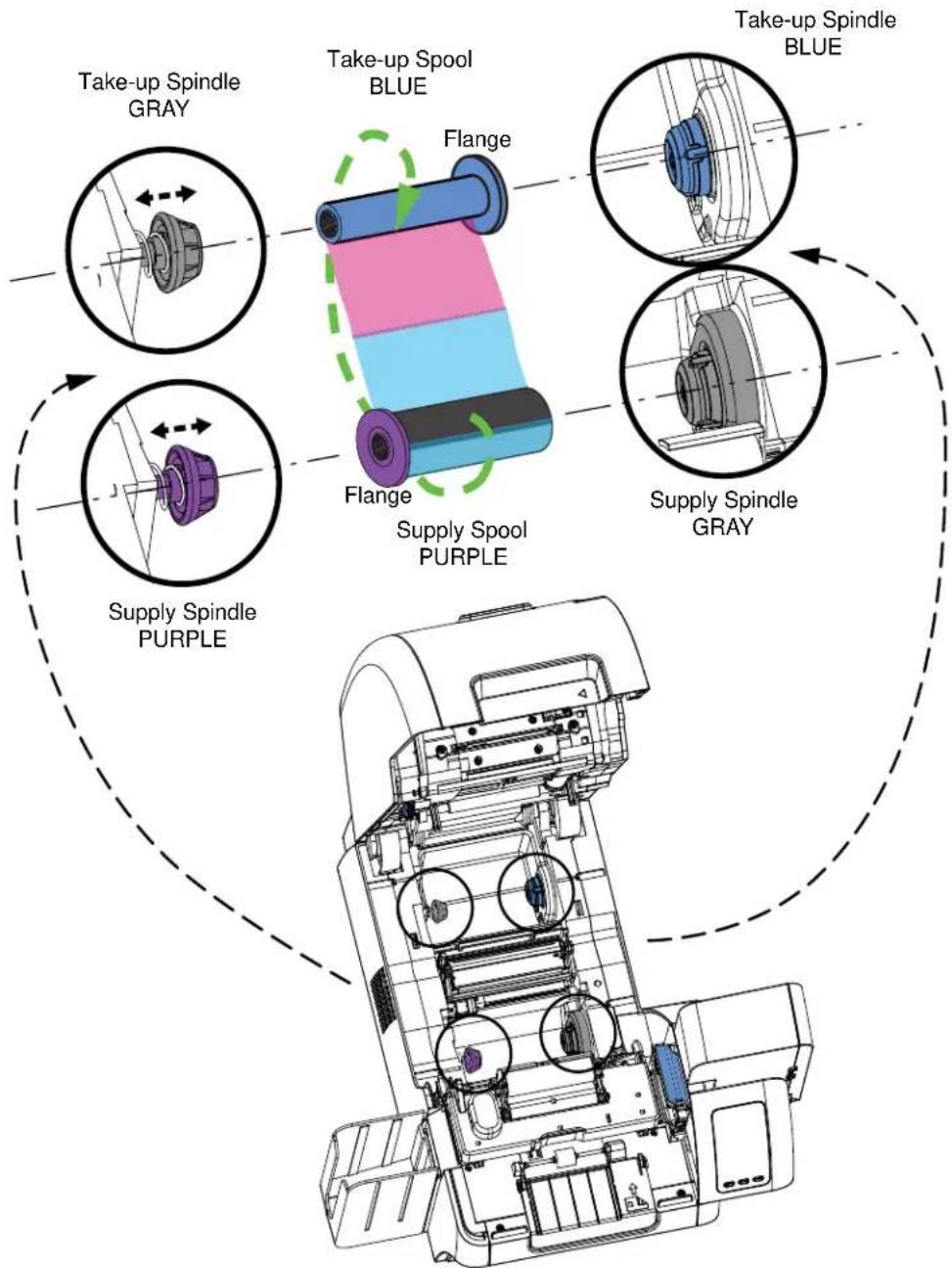
Step 2. Load the print ribbon supply spool onto the supply spindles, purple flange side to the left.
Step 3. Load the empty take-up spool onto the take-up spindle, blue flange side to the right.
Step 4. Make sure the print ribbon comes off the bottom of the supply spool and feeds to the bottom of the take-up spool.
Step 5. The figure below shows the proper installation of the print ribbon.

natural_image
Technical line drawing of a mechanical device with internal components and a magnified inset showing a highlighted section (no text or symbols present)Connecting Power

Electric Shock Caution • Limit AC power supplied to the Printer to 100 – 230 volts, 60 \~ 50 Hertz. Limit excess current draw to 16 amps or less, using an associated circuit breaker or other such device. Never operate the Printer in a location where operator, computer, or printer can get wet. Personal injury could result. The Printer must be connected to an earthed electrical power source and properly protected against electrical surges and grounding faults; the electrical reliability of the Printer is based on the reliability of the mains power source and with the earth connection.
The Printer's power supply is an internal unit that can only be serviced or replaced by trained and authorized personnel.

Step 1. Place the Printer's power switch in the OFF ( ) position.
Step 2. Depending on your local AC voltage, plug the appropriate power cord into the Printer's power connector and a grounded AC power source connection.
DO NOT SWITCH THE PRINTER ON.
Connecting the Printer to your Computer
USB Connection
Step 1. Connect the USB cable to the printer and the computer.
Step 2. Ensure that the printer's power switch in the OFF() position.

Step 1. Connect the Ethernet Port on the rear of the printer to an Ethernet Network Port.
Step 2. Turn the printer's power switch to the ON ( | ) position.

flowchart
graph TD
    A["Server"] --> B["10/100base-T"]
    B --> C["Switch"]
    C --> D["Switch"]
    D --> E["Switch"]
    E --> F["Switch"]
    F --> G["Switch"]
    G --> H["Switch"]
    H --> I["Switch"]
    I --> J["Switch"]
    J --> K["Switch"]
    K --> L["Switch"]
    L --> M["Switch"]
    M --> N["Switch"]
    N --> O["Switch"]
    O --> P["Switch"]
    P --> Q["Switch"]
    Q --> R["Switch"]
    R --> S["Switch"]
    S --> T["Switch"]
    T --> U["Switch"]
    U --> V["Switch"]
    V --> W["Switch"]
    W --> X["Switch"]
    X --> Y["Switch"]
    Y --> Z["Switch"]
Installing the Windows Printer Driver Initial Steps
Each computer that will use the printer must have the Printer Driver installed.
If not already done, connect power to the printer; and connect the printer to the computer.
- For USB Driver installation, turn the printer OFF ().
- For Ethernet Driver installation, turn the printer ON ( ).
To install the Printer Driver, insert the User Documentation and Drivers CD, included with your printer, into the host computer and the InstallShield Wizard will walk you through the required installation steps. The InstallShield Wizard will:
- Automatically install the User Interface when the driver CD is inserted. (Autorun must be enabled for your CD).
If Autorun is disabled:
a. Insert the Driver CD into the CD-ROM drive.
b. At the root (top) level of the CD, double-click on the RunCD.exe file.
- Start the installation process when the Install Printer Driver menu item is selected from the Main Menu.

- Detect previous versions of the driver. If a previous version is detected, you will be prompted to remove it, reboot, and then restart the install process.
• Install the new driver files; see USB (on Page 23) and/or Ethernet (on Page 28).
Installing the USB Printer Driver

Note • To install the Ethernet driver, see Page 28.
Step 1. If not already done, connect power to the printer. Do not turn power ON.
Step 2. Connect the USB port on the rear of the printer to the computer's USB port.
Step 3. Ensure that the Printer's power switch is in the OFF() position.
Step 4. Insert the User Documentation and Drivers CD into the CD drive of the host computer. The Main Menu will open.
Step 5. From the drop-down menu in the upper-right corner of the Main Menu, choose the appropriate language for your system.
Step 6. From the Main Menu, click Install Printer Driver.
Step 7. If an older Printer and Driver is installed on your computer, the Welcome window will be displayed; otherwise go to Step 9.
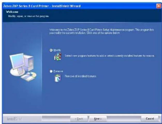
Step 8. In the Welcome window, choose the maintenance operation to be performed:
a. Select Modify to upgrade the older printer driver, click the Next button, and follow the screen prompts. At the end of the upgrade process, you will be asked to re-boot your computer. Re-boot your computer. The upgrade is complete.
b. Select Remove to remove the older printer driver, click the Next button, and follow the screen prompts. At the end of the uninstall process, you will be asked to re-boot your computer. Re-boot your computer, and start over with Step 1.

Installation and Setup
Installing the Windows Printer Driver
Step 9. The InstallShield Wizard window will open. To proceed with the installation, click the Next button.
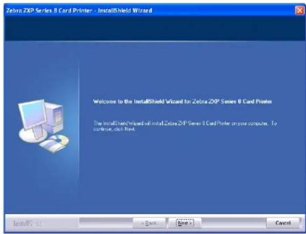
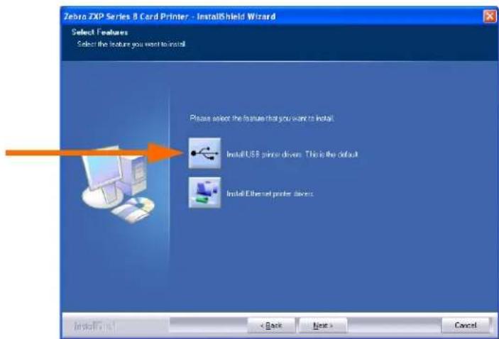
Step 10. Select Install USB printer drivers, and click the Next button.
Step 11. Ensure that the Printer's power switch in the OFF (○) position; and then click the OK button.

Step 12. This will bring up the License Agreement window. To proceed with the installation, select the I accept the terms of the license agreement option, and then click the Next button.

Step 13. This will bring up the Customer Information window. Enter User Name and Company Name; and then click the Next button.


Installation and Setup
Installing the Windows Printer Driver
Step 14. This will bring up the Choose Destination Location window.
- To accept the default destination location where setup will install the files, click the Next button.
- or -
- Select a folder where setup will install the files, and click the Next button.

Step 15. This will bring up the Ready to Install the Program window. To continue, click the Install button.
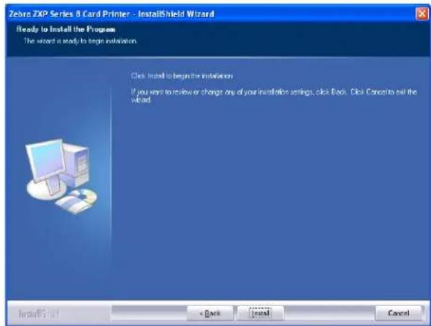
Step 16. Observe the Setup Status window.
Step 17. The Congratulations window will appear.

Step 18. At this point, turn on your printer; and then click the Next button. The Windows New Hardware Found wizard will find the printer.
Step 19. When the InstallShield Wizard Complete window appears, select the Yes, I want to restart my computer now radio button; and click the Finish button.

Step 20. This completes USB driver installation.
Step 21. To use the Printer, you would select it just like you would any other printer connected to a Windows system.
Note that you may need to change the card setup (card type, orientation, etc.), encoding, and/or black panel settings via the Printer Driver; see Printing Preferences on page 60.
Installing the Ethernet Printer Driver

Note • To install the USB driver, see Page 23.

Important • The Ethernet Network must be configured correctly, with the Printer and the host computer on the same subnet mask. Use the printer's default-configured DHCP address (there must be a DHCP server on the network) or set the Printer to a Static IP address; see Network Settings Menu on page 46. If you are not sure how to verify this or change the configuration, consult someone knowledgeable on Ethernet Networks.
Step 1. If not already done, connect power to the printer. Turn power ON.
Step 2. Connect the Ethernet port on the rear of the printer to the Ethernet network connection or directly to the computer's Ethernet port.
Step 3. Ensure that the Printer's power switch in the ON() position.
Step 4. Insert the User Documentation and Drivers CD into the CD drive of the host computer. The Main Menu will open.
Step 5. From the drop-down menu in the upper-right corner of the Main Menu, choose the appropriate language for your system.
Step 6. From the Main Menu, click Install Printer Driver.
Step 7. If an older Printer and Driver is installed on your computer, the Welcome window will be displayed; otherwise go to Step 9.
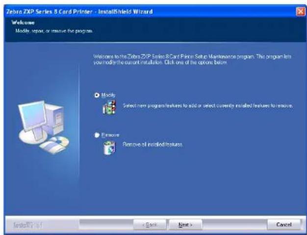
Step 8. In the Welcome window, choose the maintenance operation to be performed:
a. Select Modify to upgrade the older printer driver, click the Next button, and follow the screen prompts. At the end of the upgrade process, you will be asked to re-boot your computer. Re-boot your computer. The upgrade is complete.
b. Select Remove to remove the older printer driver, click the Next button, and follow the screen prompts. At the end of the uninstall process, you will be asked to re-boot your computer. Re-boot your computer, and start over with Step 1.
Step 9. The InstallShield Wizard window will open. To proceed with the installation, click the Next button.

Step 10. Select Install Ethernet printer drivers, and click the Next button.
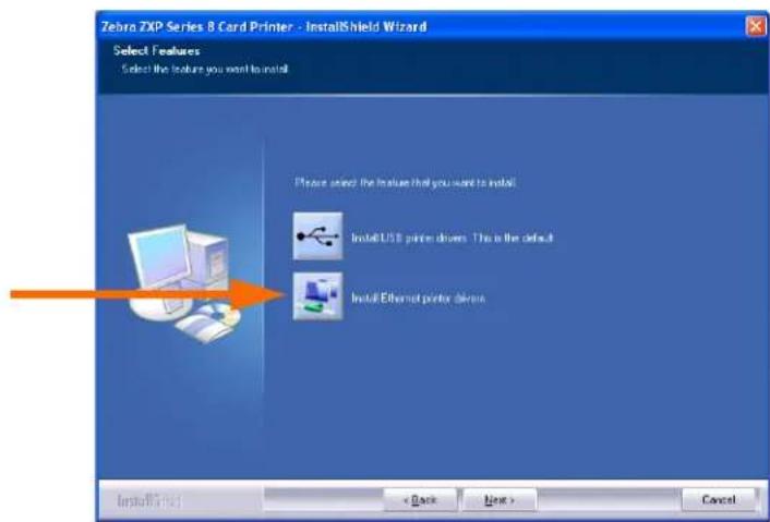
Step 11. Ensure that you have powered ON ( | ) the network printer and it is reachable from the PC; and then click the OK button.

Step 12. This will bring up the License Agreement window. To proceed with the installation, select the I accept the terms of the license agreement option, and then click the Next button.

Step 13. This will bring up the Customer Information window. Enter your name and the name of the company for which you work; and then click the Next button.

Step 14. Identify the printer:
- Click on the Search button (arrow below) to search for all the Ethernet printers on the network, select the desired printer, and then click the Next button.
- or -
- Enter the Printer IP Address directly (example circled below), and click the Next button.

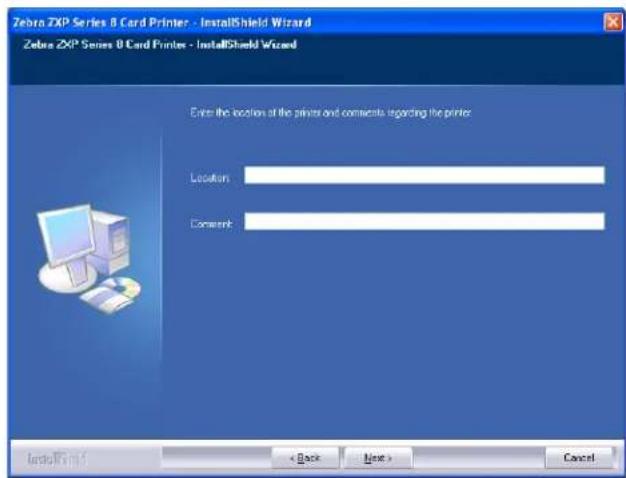
Step 15. Enter the location of the printer, and add any applicable comments; and then click the Next button.

Installation and Setup
Installing the Windows Printer Driver
Step 16. This will bring up the Choose Destination Location window.
- To accept the default destination location where setup will install the files, click the Next button.
- or -
- Click the Change button, select a folder where setup will install the files, and click the Next button.

Step 17. This will bring up the Ready to Install the Program window. To continue, click the Install button.

Step 18. Observe the Setup Status window.
Step 19. When the InstallShield Wizard Complete window appears, click the Finish button.

Step 20. This completes Ethernet driver installation.
Step 21. To use the Printer, you would select it just like you would any other printer connected to the Ethernet.

Note • You may need to change the card setup (card type, orientation, etc.), encoding, and/or black panel settings via the Printer Driver; see Printing Preferences on page 60.
natural_image
Technical line drawing of a mechanical device with no visible text or symbolsIntroduction
Printing with the Card Printer is similar to printing with any other printer in a Windows environment.
• The Printer Driver Software is installed on your computer (see Section 2).
• The Printer is connected to the power source and the computer (see Section 2).
- The Printer is selected by either the Operating System or the appropriate application software program.
- Printer Properties are set (the factory default values will be appropriate for many applications).
- Set the Card Type.
- Print a Test Card.
- Card printing is directed by the appropriate application software program.
Card Type Selection
The Card Setup tab allows you to to specify the card type in use. Based on your selection, the printer automatically adjusts various printer properties for optimum print quality.
To access the Card Setup Tab, select Start > Printers and Faxes. Right click on the Zebra ZXP Series 8 Card Printer listing; and select Printing Preferences > Card Setup.

Important • If your card type is not listed in the drop-down menu, select Custom; and fill out the Card Specifications pop-up screen; see Appendix B for details.

• Make the appropriate Card Type selection. Note that PVC is the default.
Printing a Sample Card
Sample card designs are installed with the printer driver. To print a sample card:
- Access the Card Setup Tab, select Start > Printers and Faxes. Right click on the Zebra ZXP Series 8 Card Printer listing; and select Printing Preferences > Card Setup.
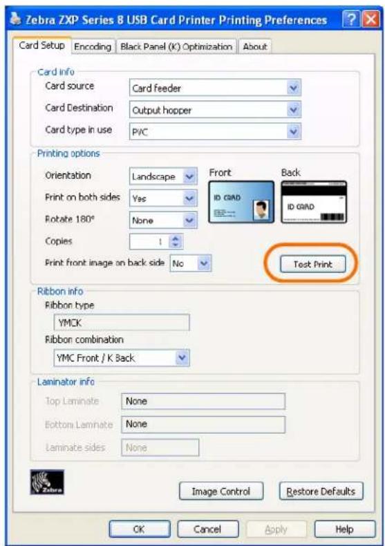
- Ensure that cards are in the Input Hopper.
- Click of the Test Print button (circled above).

Note • It is normal for the Printer to warm up to operating temperature before printing.
- The printer will feed in a card and start printing.
- Once the printing job is complete, the card is ejected from the printer into the Output Hopper.
Manual Card Feed
A Manual Feed Slot is available for feeding single cards. The Input Hopper must be empty for single-card feeding to work properly.
- Access the Card Setup Tab: Select Start > Printers and Faxes. Right click on the Zebra ZXP Series 8 Card Printer listing; and select Printing Preferences > Card Setup.
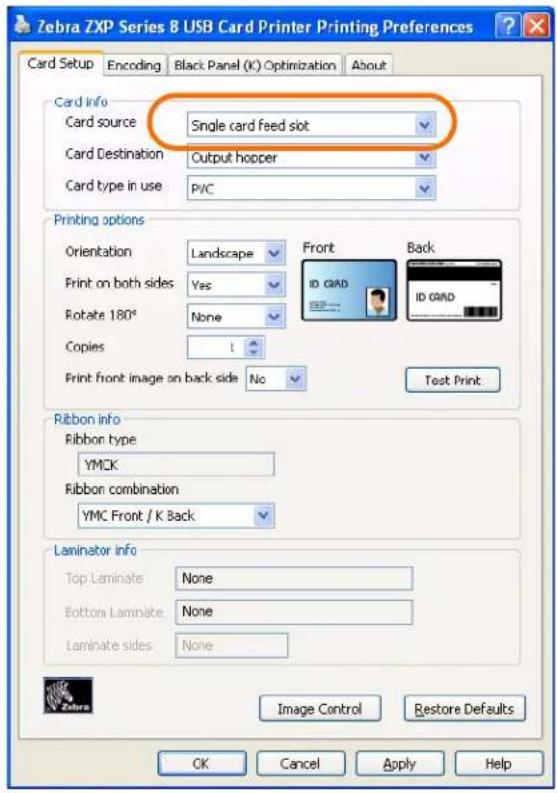
- From the Card Info > Card source dropdown menu, select the Single card feed slot (circled above).
- Click on the Apply button, and then click on the OK button.
-
Ensure that there are no cards in the Input Hopper.
-
Insert a single card into the slot in the correct orientation. Do not feed more than one card at a time.

Caution • DO NOT bend cards or touch print surfaces as this can reduce print quality. The surface of the cards must remain clean and dust free. Always store cards in an enclosed container. Ideally, use cards as soon as possible.

Operator Control Panel (OCP)
The printer is equipped with an OCP Display and three OCP Buttons which give access to the printer menus. The menus can be accessed when the printer status shows READY.

- Press the MENU button, to access the Main Menu.
- Press the INFO button, to access and view the Printer Settings Menu.
- Press the CANCEL button, to cancel the current print job in the printer.
Messages
Your printer is equipped with an OCP Display to provide printer status information. The readout is controlled by three OCP Buttons directly below the OCP Display. The messages displayed fall into three categories:
• Operational, see page 41.
- Warning, see page 42.
- Error, see page 42.
Operational Messages
| MESSAGE DESCRIPTION | |
| ALARM An error message needs | to be cleared before normal operations can resume. |
| CANCELING The Cancel button | was pressed, and the current operation is being terminated. |
| CONFIG DATA Configuration data | is being transferred from the computer to the printer. |
| CONTACT OPERATION Contact | Smart Card is being encoded; i.e., the card is in position and data is being transferred. |
| CONTACTLESS OPERATION C | contactless Smart Card is being encoded; i.e., the card is in position and data is being transferred. |
| COOLING Ready to accept a print job, rollers cooling; e.g., when switching from 2-sided printing to 1-sided printing. | |
| COOLING PRINT JOB WAITING | Print job received, cooling rollers to temperature. |
| COOLING PRINTHEAD TEMPERATURE | Cooling printhead to temperature. |
| COOLING WAITING TO LAMINATE * | Ready to accept a print job, laminator cooling; e.g., when switching from 2-sided to 1-sided laminating. |
| DIAGNOSTIC Diagnostic testing | in progress. |
| JOB DATA Data is being transferred from the computer to the printer. | |
| LAMINATING * Print job received, laminating in process. | |
| MAG OPERATION A Magnetic Stripe Card is being encoded; i.e., card is in position and data is being transferred. | |
| MANUALLY INSERT CARD FROM FRONT | Waiting for manual card feed (this function is set via the Card Setup Tab on page 61). |
| OFFLINE Status toggled (offline online) via the OCP Advanced Settings Menu. | |
| PRINTING | Print job received, printing in process. |
| READY Ready and at temperature. | |
| STANDBY | Printer is in “sleep” mode; i.e., power save mode. |
| WAIT INITIALIZING | Performing a self test on startup. |
| WARMING | Ready to accept a print job, rollers heating; e.g., at startup or when switching from 1-sided printing to 2-sided printing. |
| WARMING PRINT JOB WAITING | Print job received, warming rollers to temperature. |
| WARMING WAITING TO LAMINATE * | Ready to accept a print job, laminator warming; e.g., when switching from 1-sided to 2-sided laminating. |
| WARMING PRINTHEAD TEMPERATURE | Warming printhead to temperature. |
| WARNING | Indicates that additional OCP instructions need to be performed; e.g., PRINT RIBBON LOW, etc. |
* Message only applies to Printers with a Laminator.
Warning Messages
Warnings alert the operator to action that should be taken; the printer will generally continue operation.
| WARNING(Printer will still operate) | DESCRIPTION |
| BOTTOM LAMINATE LOW * | Indicates that the Bottom Laminate cassette is low. |
| CLEAN FRONT CARD PATH Indicates that the Front Card Path (Y-Drive Rollers) needs cleaning; seeCleaning the Printer, Section 6. | |
| CLEAN LAMINATOR * Indicates that the Laminator Path needs cleaning. | |
| CLEAN LAM ROLLERS * Indicates that the Laminator Media Feed Rollers need cleaning. | |
| CLEAN LAM OVEN * Indicates that the Laminator Transfer Path (Heated Rollers) needs cleaning. | |
| CLEAN SIDE CARD PATH Indicates that the Side Card Path (X-Drive Rollers) needs cleaning; seeCleaning the Printer, Section 6. | |
| CLEAN TRANSFER PATH Indicates that thTransfer Path (Heated Rollers) needs cleaning; seeCleaning the Printer, Section 6. | |
| PRINT RIBBON LOW | Indicates that the Print Ribbon spool is low; seeLoading a Print Ribbon, Section 2. |
| TOP LAMINATE LOW * Indicates that the Top Laminate cassette is low. | |
| TRANSFER FILM LOW Indicates that the Transfer Film spool is low; seeLoading the Transfer Film, Section 2. | |
NOTE: Message only applies to Printers with a Laminator.
Error Messages
Errors are displayed when a situation causes the printer to stop operating. Depending on the cause of the error message, restarting the printer or clearing the displayed error may return the printer to operational status; or the printer may require troubleshooting and repair.
Refer to Section 7, Troubleshooting, for a list of the error messages, possible causes, and possible solutions.
Printer Menu Information
Info Menu

flowchart
graph TD
    A["INFO Button (Operating Mode Display)"] --> B["PRINTER INFO"]
    B --> C["NETWORK INFO"]
    C --> D["RIBBON INFO"]
    D --> E["FILM INFO"]
    E --> F["PRINTHEAD USAGE"]
    F --> G["CONFIGURATION INFO"]
    G --> H["TEMPERATURE INFO"]
    H --> I["LAMINATOR INFO *"]
    I --> J["TOP LAMINATE INFO *"]
    J --> K["BTM LAMINATE INFO"]
    K --> L["LAM TEMPERATURE INFO * Displays Settings: Top and Bottom temperature; and Current: Top and Bottom temperature."]
    L --> M["LAMINATOR ODOMETER *"]
    M --> N["* Only applies to Printers with a Laminator."]
    style A fill:#f9f,stroke:#333
    style N fill:#ccf,stroke:#333
- Press the PREV button to move up the menu list
- Press the NEXT button to move down the menu list
- Press the EXIT button to return to the Operating Mode Display
Operation
Operator Control Panel (OCP)
Main Menu

flowchart
graph TD
    A["MENU Button (Operating Mode Display)"] --> B["RETURN"]
    B --> C["PRINT TEST CARDS"]
    C --> D["NETWORK SETTINGS"]
    D --> E["ADVANCED SETTINGS"]
    E --> F["Main Menu UP DOWN SELECT"]
    B --> G["See Print Test Cards Menu on page 45"]
    D --> H["Network Settings Menu on page 46"]
    E --> I["See Advanced Settings Menu on page 47"]
- Press the UP button to move up the menu list
- Press the DOWN button to move down the menu list
- Press the SELECT button to select the item from the list.
Print Test Cards Menu

flowchart
graph TD
    A["Main Menu"] --> B["RETURN"]
    B --> C["COUNT"]
    C --> D["SIDES"]
    D --> E["CARD TYPE"]
    E --> F["Mid Gray"]
    F --> G["Grid On Gray"]
    G --> H["Grid On Gray 2"]
    H --> I["UP DOWN SELECT"]
    I --> B
    style A fill:#f9f,stroke:#333
    style B fill:#ccf,stroke:#333
    style C fill:#cfc,stroke:#333
    style D fill:#fcc,stroke:#333
    style E fill:#cff,stroke:#333
    style F fill:#ffc,stroke:#333
    style G fill:#cfc,stroke:#333
    style H fill:#fcc,stroke:#333
    style I fill:#ffc,stroke:#333
- Press the UP button to move up the menu list
- Press the DOWN button to move down the menu list
- Press the SELECT button to select the item from the list.
Operation
Operator Control Panel (OCP)
Network Settings Menu

flowchart
graph TD
    A["Main Menu"] --> B["RETURN WITHOUT SAVE"]
    B --> C["SAVE SETTINGS"]
    C --> D["DHCP MODE"]
    D --> E["SET IP ADDRESS"]
    E --> F["SET SUBNET MASK"]
    F --> G["SET DEFAULT GATEWAY"]
    G --> H["Network Settings Menu UP DOWN SELECT"]
    H --> B
    D --> I["Enable or disable the DHCP Mode"]
    E --> J["Change the IP Address"]
    F --> K["Change the Subnet Mask"]
    G --> L["Change the GW (Gateway)"]
- Press the UP button to move up the menu list
- Press the DOWN button to move down the menu list
- Press the SELECT button to select the item from the list.
Advanced Settings Menu
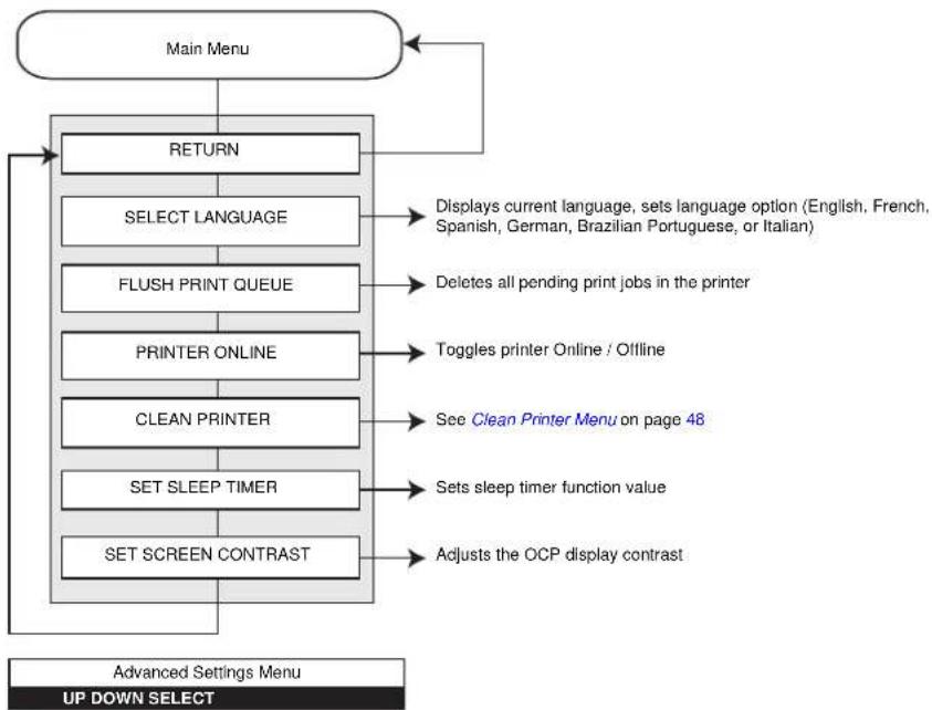
flowchart
graph TD
    A["Main Menu"] --> B["RETURN"]
    B --> C["SELECT LANGUAGE"]
    C --> D["FLUSH PRINT QUEUE"]
    D --> E["PRINTER ONLINE"]
    E --> F["CLEAN PRINTER"]
    F --> G["SET SLEEP TIMER"]
    G --> H["SET SCREEN CONTRAST"]
    H --> I["Adjusts the OCP display contrast"]
    I --> J["Displays current language, sets language option (English, French, Spanish, German, Brazilian Portuguese, or Italian)"]
    J --> K["Deletes all pending print jobs in the printer"]
    K --> L["Toggles printer Online / Offline"]
    L --> M["See Clean Printer Menu on page 48"]
    M --> N["Sets sleep timer function value"]
    N --> O["Advanced Settings Menu UP DOWN SELECT"]
- Press the UP button to move up the menu list
- Press the DOWN button to move down the menu list
- Press the SELECT button to select the item from the list.
Operation
Operator Control Panel (OCP)
Clean Printer Menu

flowchart
graph TD
    A["Advanced Settings Menu"] --> B["RETURN"]
    B --> C["CLEAN SIDE CARD PATH"]
    C --> D["CLEAN FRONT CARD PATH"]
    D --> E["CLEAN HEATER ROLLERS"]
    E --> F["CLEAN LAMINATOR *"]
    F --> G["CLEAN LAM ROLLERS *"]
    G --> H["CLEAN LAM OVEN *"]
    H --> I["Clean Printer Menu UP DOWN SELECT"]
    B --> J["Refer to Section 6, Cleaning, for detailed cleaning instructions"]
    C --> K["Use the X Roller Cleaning Card, and step through the cleaning process"]
    D --> L["Use the Y Roller Cleaning Card, and step through the cleaning process"]
    E --> M["Use the Hot Roller Cleaning Card, and step through the cleaning process"]
    F --> N["Use the Laminator Cleaning Card, and step through the cleaning process"]
    G --> O["Use the Cleaning Swab, and step through the cleaning process"]
    H --> P["Use the Laminator Hot Roller Cleaning Card (with adhesive), and step through the cleaning process. * Only applies to Printers with a Laminator."]
- Press the UP button to move up the menu list
- Press the DOWN button to move down the menu list
- Press the SELECT button to select the item from the list.
Ethernet Indicators -- Detail

Link/Activity Indicator (Green)
| Off No link (disconnected) |
| On Network link has been established |
| Blinking Network activity has been detected |
Speed Indicator (Orange)
| Off No link (disconnected) | |
| 1 Blink The | LED blinks once (one blink, pause, one blink, etc.) when a 10Base link has been established. |
| 2 Blinks The | LED blinks twice (two blinks, pause, two blinks, etc.) when a 100Base link has been established. |

natural_image
Technical line drawing of a mechanical device with no visible text or symbolsPrinter Settings and Adjustments

natural_image
Abstract black and white pattern with curved white lines on black background (no text or symbols)Introduction
This section describes settings and adjustments that can be made to your Windows Driver. This consists of two major topics:
Properties....52
Printing Preferences 60
Properties
To access Properties, select Start > Printers and Faxes. Right click on the Zebra ZXP Series 8 Card Printer listing, then select Properties

- General Tab - Displays printer information of a general nature, includes selection for Printing Preferences and Print Test Page (i.e., the standard Windows test page).
- Sharing Tab - Operating System (OS) feature where the printer can be shared with other clients on a network.
- Ports Tab - OS feature displays available communication ports.
- Advanced Tab - OS feature to select printer availability and spooling options.
• Color Management Tab - Allows user to define color profile(s) with color printers.
• Security Tab - OS feature where permissions to printers can be defined. - Device Information Tab - Allows user to make basic printer adjustments and access advanced printer controls.
General Tab
The General tab shows the printer model and lists the features of the printer.
To access the General tab, select Start > Printers and Faxes. Right click on the Zebra ZXP Series 8 Card Printer listing. Select Properties > General.

- Location - Lets you specify where the printer is located.
- Comment - Lets you specify general information about the printer, such as the type of print device and who is responsible for it. Once set, these fields can be displayed by applications.
- Model - Specifies the name of the printer driver installed.
- Features - Specifies whether various options are available on the printer.
The Printing Preferences button takes you to Printing Preferences used to set selected configuration parameters; see Printing Preferences on page 60
The Print Test Page button sends the standard Windows test page to the printer.
Sharing Tab
On the Sharing tab (Sharing Property Page), you can choose to share the printer over the network and install additional drivers to accommodate different operating systems.
To access the Sharing tab, select Start > Printers and Faxes. Right click on the Zebra ZXP Series 8 Card Printer listing. Select Properties > Sharing.

Printer sharing tasks that you can perform include:
- To share a printer, select the Share this printer radio button; and specify a name for the shared resource. Click OK when you're finished.
- To change the shared name, simply enter a new name in the Share name field; and click OK.
- To quit sharing a printer, select the Do not share this printer radio button. Click OK when you're finished.
Ports Tab
Use the Ports tab to specify the computer port to which the printer is connected. This will have been established at the initial installation of the printer, and will not normally require attention.
To access the Ports tab, select Start > Printers and Faxes. Right click on the Zebra ZXP Series 8 Card Printer listing. Select Properties > Ports.

An exception to this is if you wish to use printer pooling, the ability to distribute print jobs to multiple printers; see Pooling on page 169 for details.
To enable printer pooling, check the “Enable printer pooling” box, then check the additional ports boxes. Each port should have a single Zebra printer installed on it. All the pooled printers must be identical models with the same configuration (e.g., all with YMC front, K back); and each must have its own printer driver installed.
Now, when you print to the “main printer” (that is, whichever printer you right-clicked in Printers and Faxes to get to this screen), this printer will get print jobs until it has buffered as many jobs as it can take. Remaining jobs will then “spill over” to other printers until all printers in the pool are busy.
Advanced Tab
The Advanced tab determines the spooling (queuing) of print jobs and determines how spooled jobs are handled relative to the most recent job.
To access the Advanced tab, select Start > Printers and Faxes. Right click on the Zebra ZXP Series 8 Card Printer listing. Select Properties > Advanced.

To enable spooling: Select the radio button labeled Spool print documents so program finishes printing faster.
- Select Start printing after last page is spooled if you want the entire document to be spooled before printing begins. This option ensures that the entire document is sent to the print queue before printing. If for some reason printing is canceled or not completed, the job will not be printed.
- Select Start printing immediately if you want printing to begin immediately when the print device is not already in use. This option is preferable when you want print jobs to be completed faster or when you want to ensure that the application returns control to users as soon as possible.
To disable spooling: Select the radio button labeled Print directly to the printer radio button.
Color Management Tab

Important • The optimal color profile is automatically selected when the card type is selected; see the Printing Preferences, Card Setup Tab.
Color Management settings allow you to associate color profiles on the printer based on the type of media being used and printer configuration. The Add button allows the operator to add additional profiles to the color profile list.
To access the Color Management tab, select Start > Printers and Faxes. Right click on the Zebra ZXP Series 8 Card Printer listing. Select Properties > Color Management.
![Zebra ZXP Series 8 USB Card Printer Properties General Sharing Ports Advanced Color Management Security Device Information These settings let you associate color profile(s) with your color printer. Color profiles control the color on your printer based on the type of media being used and the printer configuration. Automatic: Windows will automatically select the best color profile from the list of associated color profiles [Recommended] Manual: Manually select the default color profile for all output from this device from the list of associated color profiles Default color profile: Color Profiles currently associated with this printer: Add... Remove Set As Default OK Cancel Apply Help](/content/2026/05/1028953/images/b7f94a108eb8c3a0ce89a178e8628dc2b6687d005807c6afb55b6e8f446b9436.jpg)
The following settings let you associate color profiles with your printer:
- The Automatic radio button lets Windows select the best color profile from the list of associated profiles (default).
- The Manual radio button lets you select the appropriate profile from the list shown in the Color Profile window.
You can manage Color Profiles currently associated with your printer as follows:
- The Add button allows you to add additional profiles to the color profile list.
- The Remove button allows you to remove profiles from the color profile list.
- The Set As Default button allows you to set the selected profile as the default profile.
Security Tab
This is the standard Windows security screen, showing user access to various printer control options. Both Print and Manage Printers must be checked for full functionality of the printer.
To access the Security tab, select Start > Printers and Faxes. Right click on the Zebra ZXP Series 8 Card Printer listing. Select Properties > Security.

The Security tab allows you to assign the actual permissions that apply to the print queue. You can apply permissions to both users and to groups. It is usually considered a better practice to only apply security to groups.
The Advanced Security Settings properties sheet allows you to assign a more comprehensive set of permissions than the basic Security tab found on the printer's properties sheet does.
Device Information Tab
The Device Information tab provides device information, security status, and printer usage. Access to Media Info and ZXP ToolBox is included.
To access the Device Settings tab, select Start > Printers and Faxes. Right click on the Zebra ZXP Series 8 Card Printer listing. Select Properties > Device Information.

• The Media Info button takes you to the Media Info screen which shows:
- The color ribbon type, part number, and the number of color panel sets remaining
- The transfer film type, part number, and the number of transfer film panels remaining
- The ZXP Toolbox button takes you to the ZXP Toolbox which provides advanced configuration capabilities and tools to manage the operation of your printer; see Section 5 for details.
Note that the ZXP Toolbox is a separate application that works independently from the printer driver.
Printing Preferences
To access the Printing Preferences, select Start > Printers and Faxes. Right click on the Zebra ZXP Series 8 Card Printer listing; and select Printing Preferences.

- Card Setup Tab - Allows user to adjust selected card and print job parameters.
• Encoding Tab - Allows the user to set various magnetic encoding options. - Black Panel (K) Tab - Displays available options for Black Extraction.
- About Tab - Displays copyright and driver version information about the printer driver.
The OK button saves your settings.
The Cancel button abandons changes made.
The Apply button applies your settings.
The Help button will enable you to view a corresponding page of help information.
Card Setup Tab
Card Setup tab allows the user to adjust selected card and print job parameters.
To access the Card Setup Tab, select Start > Printers and Faxes. Right click on the Zebra ZXP Series 8 Card Printer listing; and select Printing Preferences > Card Setup.
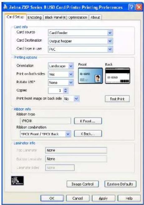

- Card Info allows the user to select the Card Source, Card Destination, and Card Type.
- Card type in use allows the user to specify the card type in use. Based on your selection, the printer automatically adjusts various printer properties for optimum print quality.
- Printing options allows the user to select the card orientation, to print on both sides of the card, to rotate the card 180°, and to specify the number of copies to print. The Test Print button prints a test card.
- Ribbon info:
- Ribbon type is the color ribbon installed in the printer. This is not user selectable.
- Ribbon combination allows you to apply color or black, or both, to either side of the card.
Advanced Black Panel Options Pop-Up
The Advanced Black Panel Options pop-up window allows you to manage and configure Black Extraction. This window is available when using Black Panel (K-Panel) ribbons; e.g., YMCK, YMCKK, etc.
This window controls how the driver selects the text and/or graphics to be printed with the Black Panel.
To access the Advanced Black Panel Options pop-up window, select Start > Printers and Faxes. Right click on the Zebra ZXP Series 8 Card Printer listing, and select Printing Preferences > Card Setup. Select Ribbon info > K Front ... or K Back...
The figure below shows settings for the front side of the card; settings for the back side of the card are identical.

- Set black panel extraction type:
- Disable black extraction treats all non-black specified elements as composite black (YMC).
- Print YMC black under K is used to print composite black (YMC) under the K panel. When selected, the operator can choose to do this by selecting certain areas or types of data (e.g., text, graphics, etc) via the Area manager.
- Print all black data specifies all black data to be printed with K.
- Apply black extraction on: Specify Black text, Black graphics, or Black monochrome bitmaps. The driver will automatically determine the best K-Panel setting based on the card design elements.
- Black extraction from color images:

- Print black with K panel: Specify the zones as Defined areas, Undefined areas, or Full card.
- Black level: The driver evaluates the RGB values of the card design and looks for an RGB value of 000 in order to determine what should be printed in Black.
Using the Black Panel Options, specify what text or graphics, within your card design, are to be printed via composite (YMC) black, K-Resin black, or both.
Then use Black Level to select RGB values higher than the default of 000, to print with the K-resin panel. This allows the range to be expanded up to 555.
- Area manager: This option is enabled when either the Defined areas (extract inside the zone) or the Undefined areas (extract outside the zone) radio button is selected. Note that a defined area is a zone.
This option is used when a particular area of the card has text or other elements that you want treated as Print black with K panel.
- Orientation: Set the card orientation to either Portrait or Landscape.
- Units: Set the units to either inches or mm (millimeters)
- Area: Use to define, select, move, or resize a zone; use to draw a zone; and use to delete a selected zone.
To create a zone, "drag" the cursor diagonally across the card area (dashed outline) to define the location of the zone. Note that multiple zones can be defined. Dimensions are referenced to the upper-left corner of the card.
The Restore Defaults button restores Advanced Black Panel Options default values.
Uv Panel Pop-Up
A Uv Panel is a resin-based coating similar to a "K" panel and is used to print invisible images (text or graphics) that will glow in the visible spectrum when exposed to a Black Light.
The Uv Panel pop-up window allows you to manage and configure printing with a Uv Panel. This window is only available when using Uv ribbons (e.g., YMCUvK) and is automatically enabled in the driver when a recognized YMCUvK ribbon is installed.
To access the Uv Panel pop-up window, select Start > Printers and Faxes. Right click on the Zebra ZXP Series 8 Card Printer listing, and select Printing Preferences > Card Setup. Select Ribbon info > Front Uv... or Back Uv...
The figure below shows settings for the front side of the card; settings for the back side of the card are identical.

- Select the Uv type:
- Disable Uv: Default, no Uv panel will be applied.
- Full Uv varnish: Prints the entire card with full Uv panel.
- Selected area blank: Using the Area Manager (described on next page) allows you to create one or more rectangles to exclude from Uv print.
- Selected area Uv varnish: Using the Area Manager (described on next page) allows you to create one or more rectangles to print.
- Bitmap based Uv varnish: Allows you to import a bitmap image to print on the Uv panel; e.g., import a security seal.
- Uv printing options: Note that Rotate 180^ , Grayscale, and Halftone are enabled when Bitmap based Uv varnish (see above) is selected.

- Double pass: Use this option to optimize the quality of the Uv image. This is a two-step process: 1) print and transfer the card without the Uv image, 2) print and transfer the card a second time with the Uv image only, on top of the existing print image. Note that this option uses an additional transfer panel.
- Bitmap-based Uv varnish: This option is enabled when Bitmap based Uv varnish (see above) is selected. To locate the bitmap, click on the Browse button to bring up a dialog for choosing the file.
- Area manager: Note that this option is enabled when either the Defined areas or the Undefined areas radio button is selected. A defined area is a zone.

- Orientation: Set the card orientation to either Portrait or Landscape.
- Units: Set the units to either inches or mm (millimeters)
- Area: Use to define, select, move, or resize a zone; use to draw a zone; and use to delete a selected zone.
To create a zone, “drag” the cursor diagonally across the card area (dashed outline) to define the location of the zone. Note that multiple zones can be defined. Dimensions are referenced to the upper-left corner of the card.
The Restore Defaults button restores Advanced Black Panel Options default values.
Inhibit Pop-Up
The Inhibit pop-up window allows you to select the inhibit panel area for mag stripe, signature panel, or other non-printing areas of a card. This window is available only when using ribbons with an inhibitor panel; e.g., YMCKi.
To access the Inhibit pop-up window, select Start > Printers and Faxes. Right click on the Zebra ZXP Series 8 Card Printer listing, and select Printing Preferences > Card Setup. Select Ribbon info > Front Inhibit... or Back Inhibit...
The figure below shows settings for the front side of the card; settings for the back side of the card are identical.

- Select the inhibit panel area:
- Disable Inhibit: Default.
- Inhibit printing on magnetic stripe: Places a no-print zone around the mag stripe area.
- Inhibit printing on smartcard contact: Places a no-print zone around the smartcard chip area.
- Custom file based inhibit area: See below.
- Bitmap based inhibit panel area: This option is enabled when Custom file based inhibit area (see above) is selected. To locate the bitmap, click on the Browse button to bring up a dialog for choosing the file.
Image Control Option
The Image Control button brings up the Image Control window, which lets you make color adjustments to compensate for camera or lighting conditions.
Keep in mind that these color adjustments modify how the pictures print. The adjustments do not affect the image files. (That type of adjustment would be made in an image processing application program.)

- The Multi-tone printing with one-color ribbon dropdown menu lets you select Dither error diffusion, Dither halftoning, or Dither pure black on white.
- Full color printing adjustments (-25 to +25 range) include Brightness, Contrast, Gamma, Saturation, Red, Green, and Blue.
- Sharpening filter options are None, Normal, and High. Note that these adjustments have no effect on the preview image.
Color Management: Depending on the radio button selected, you can use the color matching profile selected in Properties > Color Management or disable the color matching profile.
The OK button saves your settings.
The Cancel button returns you to the Setup Tab. Changes made are abandoned.
Encoding Tab
The Encoding screen allows the user to set various magnetic and smart card encoding options.
To access the Encoding Tab, select Start > Printers and Faxes. Right click on the Zebra ZXP Series 8 Card Printer listing; and select Printing Preferences > Encoding.
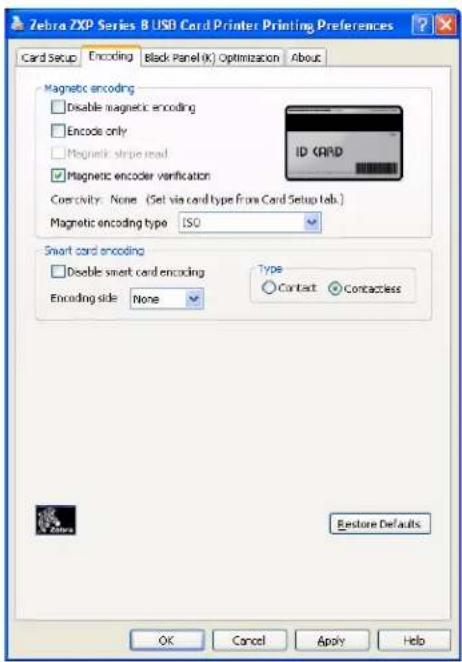
Although these options are user-selectable, they are set automatically when the Card Type is selected in the Card Setup Tab on page 61.
- Magnetic encoder verification: When selected, the protocol is (1) Write mag data; (2) Verify mag data; (3) If this fails, verify again; (4) If the second verify fails, rewrite and verify; (5) If this cycle fails, eject the card.
- Magnetic encoding type: Selections are ISO, AAMVA, CUSTOM, and BINARY; for details see Magnetic Encoding Type on page 175.
The Restore Defaults button restores Encoding default values.

Note • For advanced settings, see Section 5, ZXP Series Toolbox.
Black Panel (K) Tab
The Black Panel (K) Tab allows for special handling of black.

Note • The Black Panel (K) Tab applies only to surfaces of the card on which both YMC (color) and K (black) are to be printed.
To access the Black Panel (K) Tab, select Start > Printers and Faxes. Right click on the Zebra ZXP Series 8 Card Printer listing; and select Printing Preferences > Black Panel (K).

Select the appropriate radio button (Text, Barcode, Pictures, or Mixed) for optimized print quality.
The Restore Defaults button restores Black Panel default values.

Printer Settings and Adjustments
Printing Preferences
About Tab
The About Tab shows the copyright and the driver version for the Zebra ZXP Series 8 Card Printer.
To access the About Tab, select Start > Printers and Faxes. Right click on the Zebra ZXP Series 8 Card Printer listing; and select Printing Preferences > About.

ZXP Series Toolbox

natural_image
Abstract black and white pattern with curved white lines on a black background (no text or symbols)Introduction

Important • Use of the ZXP SeriesToolbox is intended only for advanced users and system administrators.
The ZXP Series Toolbox provides advanced configuration capabilities and tools to manage the operation of your printer. Note that the ZXP Series Toolbox is a separate application that works independently from the printer driver.
ZXP Series Toolbox Access
To access the ZXP Series Toolbox from the printer driver, select Start > Printers and Faxes. Then right-click on the Zebra ZXP Series 8 Card Printer listing, and select Properties > Device Information > ZXP ToolBox.

The ZXP Series Toolbox can also be accessed via Start > All Programs > Zebra ZXP Series 8 Card Printer > ZXP ToolBox.
Information
Printer
This information cannot be edited or changed by the user; however, this information may be useful for Zebra trained and certified personnel in diagnosing or evaluating printer status.
- Firmware and Driver lists the versions of the Firmware (Firmware, HCB, and MAB) and the version of the Driver.
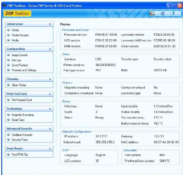
- Other shows the Interface, the Transfer type, and the Card type in use, RAM, and Printer serial no.
- Options shows the options installed -- Magnetic encoding, Contact smartcard, and Contactless smartcard.
- Status displays Warnings, Faults, and Status; Input and Output speeds (single and double); Top and Bottom transfer temperatures.
• Network Configuration lists the IP address, Gateway, Subnet mask, and MAC address. - OCP shows the Language displayed in the Operator Control Panel and the LCD contrast level selected.
- Odometer shows the number of Cards printed and the number of Printhead lines printed.
Sensors
These characteristics cannot be edited or changed by the user; however, this information may be useful for Zebra trained and certified personnel in diagnosing or evaluating printer sensors status.
- Sensor States details the state of each printer sensor.

- Sensor Values details the value of each printer sensor.
- Ribbon Take-up Motor lists various electrical characteristics of the motor.
Media
This screen displays ribbon and transfer film. This data is automatically read and updated from the installed media in the printer.
- Ribbon Details include Type, Description, Zebra part number, Initial size, Images remaining.

- Transfer Film Details include Type, Description, Zebra part number, Initial size, Images remaining.
Configuration
Image Control
The Image Control window lets you make color adjustments to compensate for camera or lighting conditions.
Keep in mind that these color adjustments modify how the pictures print. The adjustments do not affect the image files. (That type of adjustment would be made in an image processing application program.)

- The Monochrome Conversions dropdown menu lets you select Dither error diffusion, Dither halftoning, or Dither pure black on white.
• Full Color Printing adjustments (-25 to +25 range) include Brightness, Contrast, Gamma, Saturation, Red, Green, and Blue. - Sharpening Filter options are None, Normal, and High. Note that these adjustments have no effect on the preview image.
Depending on the radio button selected, you can use the color matching profile selected in Properties > Color Management or you can disable the color matching profile.
The Save button saves your image control settings.
The Restore Defaults button restores the image control default values.
Job Log

Note • Job Logs and Printer Logs are stored in the following default location: C:\Documents and Settings\All Users\ZMotif
The Job Log is a utility that builds a database of card transactions in the printer's host computer. The Job Log records the data encoded on the card's magnetic stripe, together with date, time, and the printer's serial number.
The data set can be uploaded at any time to a central archive, thus providing a means for security officers to validate a card by comparing it with tamper-proof real data.

- Enable logging - If this box is checked, the logging feature is enabled.
-
Log File Definition - Choose one of the following options:
-
If the "Create new log file each day" box is unchecked, the data is saved to a log file of your choice (Filename).
- If the box is checked, the data is saved to log file ZXPLog with the day's date; e.g., ZXPLog_2009_3_4.
- In addition to the Filename, you may wish to enter a special field Separator Character. The default field Separator Character is "|".
- Log File Contents - The Log File Contents group selects the data to be logged in the file you specified above. The data will be logged in the order displayed on the screen, each field being separated by the character specified in the Logfile Definition, Separator.
Log File Contents selections include:
- Time: Logs the time a which the card was sent to the printer in the HH:MM:SS format. The 24-hour clock is used, so 13:00:00 = 1:00 pm, and 05:00:00 = 5:00 am.
- Date: Logs the date the card was sent to the printer in the MM/DD/YYYY format.
- Printer serial number: Logs the serial number of the printer that printed the card.
- Static text: Adds to the record text in the box at right, 16 characters maximum.
- IP address: Logs the IP address of the PC that sent the card to the printer.
- Magnetic Track 1, 2, 3 Data: Logs the data sent to the printer to be encoded on the card's magnetic stripe.
- EIN data from Mag Track 2: Not implemented.
- Application will send data with “ \~L=xxx” TextOut: Allows third-party applications to send data to be logged in much the same way as they would send magnetic data.
- Spooler job number: Logs the number which the card print job was assigned in the Windows print spooler.
- User name: Logs the username of the person submitting the card print job.
- ZML Job ID: Logs the UUID; or, in a Windows environment, the GUID.

Note • Job Logs and Printer Logs are stored in the following default location:
C:\Documents and Settings\All Users\ZMotif
The Save Job Log Settings button saves the Job Log settings.
The Save Printer Log Files button creates the following XML Log Files:
- GetLogCleanHistory.xml
- GetLogErrors.xml
- GetLogEventHistory.xml
- GetLogServiceHistory.xml
Save/Restore
When you set up a printer, you can save the printer and driver configuration settings; then, when you restore or add additional printers, you can use the saved configuration to ensure configuration consistency.
Note that the Saved/Restored Settings (circled below) are for the Printer.


Note • The configuration files are stored in an XML format in the following default location: C:\Documents and Settings\All Users\ZMotif\Config
- The Save buttons save the Driver Settings and/or Printer Settings in an XML file format.
- The printer configuration settings are stored as P_
- The driver configuration settings are stored as D_
• The Restore buttons restore the Driver Settings and/or Printer Settings.
Firmware and Settings
The Firmware Download screen allows you to download firmware and firmware updates. Note that firmware updates can also be found at http://zebracard.com under Drivers & Downloads.

- Select Firmware to Download: Use this option to install the firmware downloaded from the Zebra web site to a directory on your computer.
- Click on the Download button.
- From the Browse window, "find" the downloaded firmware (BIN file type), and click on the Open button.
- Read the ZXP Toolbox caution message. If you are satisfied with the download, click on the OK button to install the firmware; otherwise click on the Cancel button to abandon the firmware installation.
- Check Firmware Updates: To use this option, you must have an internet connection.

-
Click on the Check Updates button.
-
Enter the Server name, User name, and Password in the Ftp Login pop-up, and click on the OK button.
-
Observe the firmware update file(s) displayed in the Filename listing.
-
Select the desired update file from the list.
-
Click on the Download File button.
-
As the file is downloaded, observe the % complete bar. If you selected the the Keep downloaded file locally checkbox, the update file will also be saved to your computer at C:\Documents and Settings\ZMotifFirmware.
-
Click the OK button when the Download completed pop-up appears.
-
Read the ZXP Toolbox caution message. If you are satisfied with the download, click on the OK button to install the firmware; otherwise click on the Cancel button to abandon the firmware installation.
- OCP: This section allows you to change the Language displayed in the Operator Control Panel (English, French, Spanish, German, Brazilian Portuguese, or Italian) and adjust the LCD Contrast level selected (the level ranges from 20 to 50).
• Network Configuration: This section allows you to change the various network configuration parameters (DHCP, IP address, Gateway, Subnet mask, and MAC address).
- Print Performance Setting: Performance options from the dropdown menu include:
• Standard performance and error handling
• Optimized for performance
- Optimized for error recovery
• Temperature and Position Settings

- Transfer Temperature Offset:

Note • While you will not see a change in card parameters for a given card type when using the Transfer Temperature Offsets, you will see the change in the OCP Info screen that shows the temperature set-points and current temperatures.
Transfer Temperature Offset is provided to globally change the temperature of the heated rollers. If you have a single card type that you want to change the roller temperatures, you would use custom card type. If the printer seems to be running too cold or too hot for every card type, you would use this adjustment to raise or lower the heated roller temperature for all cards. This will not affect what you see in the card parameters for a given defined card type; see Note above. The adjustment range is: Minimum -10, Maximum 10.
- Print Position:
Film print X offset (dots): This is the number of dots (300 dpi / \~3 mils/dot.) to shift the image to align it on the media. Increasing these values move the image right while decreasing them moves the image left. This parameter can be used to center the image on the card, or to align it with an edge. The adjustment range is: Minimum -50, Maximum 50.
Film print Y offset (mils): This is the number of mils to shift the image to align it on the media. Increasing these values moves the image up while decreasing them moves the image down. This parameter can be used to center the image on the card, or to align it with an edge. The adjustment range is: Minimum -100, Maximum 100.
The Save Settings button saves any changes you have made to this screen.
The Advanced Setting button provides access to service-related tests and adjustments. Use is password protected and limited to Zebra-authorized service personnel.
Cleaning
Clean Printer
The Clean Printer screen gives you the option to clean the printer via the Toolbox; refer to Section 6, for cleaning via the OCP.

- Side Card Path
When you click on the Clean button, instructions will appear in the following sequence:
- Remove the card hopper, and click Ok.
- Insert the X Roller Cleaning Card in the side slot where the card hopper was located. Click Ok after inserting the cleaning card.
- Wait until the cleaning process completes. The card will eject through the side slot.
- Flip the cleaning card. Insert the card through the side slot. Click Ok.
- Wait until the cleaning process completes. The card will eject through the side slot.
- Observe the message, Side card path cleaning successful.
- This concludes the side card path cleaning process.
- Front Card Path
When you click on the Clean button, instructions will appear in the following sequence:
- Insert the Y Roller Cleaning Card in the front feed slot. Click Ok after inserting the card.
- Wait until the cleaning process completes. The card will eject through the front feed slot.
- Flip the cleaning card. Insert the card through front feed slot. Click Ok.
- Wait until the cleaning process completes. The card will eject through the front feed slot.
- Observe the message, Front card path cleaning successful.
- This concludes the front card path cleaning process.
- Heater Rollers
When you click on the Clean button, instructions will appear in the following sequence:
- Open the printer cover, remove the transfer film, and close the cover. Then, click Ok.
- Observe the top and bottom transfer temperatures cool. Wait until the transfer temperatures fall below 70^ C before proceeding to the next step.
- Remove the backing from the Hot Roller Cleaning Card. Insert the card in the front feed slot. Click Ok.
- Wait until the cleaning process is completed. The card will eject through the front feed slot.
- Flip the cleaning card. Insert card in the front feed slot. Click Ok.
- Wait until cleaning process is completed. The card will eject through the front feed slot.
- Replace the transfer film.
- Observe the message, Transfer roller cleaning successful.
- This concludes the heater roller cleaning process.
Print Test Card
Print Sample Card

Note • The sample cards in the Test Card Library are .bmp images stored in the following default location: C:\Documents and Settings\All Users\ZMotif\Library
- View the Test Card Library. Use the scrollbar to view all the selections.

- Set the front side:
a. Select (click on) a card from the Test Card Library.
b. Click on the Set As Front button.
c. View the selected card in the Preview. Note that to remove the selected card from the Preview, click on the Set As Front button.
d. To change your selection, repeat Steps a through c.
- Set the back side: same as Step 2, except click on the Set As Back button.
- When satisfied with your selection, click on the Print button to print the sample card.
The Printing Preferences button takes you to the Printer Preferences, Card Setup Tab.
The Print Configuration Test Card button provides printer configuration data on a card.
The Reprint Last Card button sends a command to the printer to print the last card.
Technology

Note • Magnetic Encoding and Smart Card default values are set via the Card type in use option in the Card Setup tab, see page 61)
Magnetic Encoding
The Magnetic Encoding screen allows the user to test various magnetic encoding options. For more information on magnetic encoding, refer to Appendix D.

Settings: EIN options not implemented.
Read Data:
• Coercivity: Select either High or Low.
- Track selection:
- For encoding: Click on the checkboxes to select Track 1, Track 2, and/or Track 3; enter the data to be written; and click on the Encode button.
- For reading: Click on the checkboxes to select Track 1, Track 2, and/or Track 3; click on the Read button, and validate the data read.
Smart Card
The Smart Card screen allows the user to test various smart card encoding options. For more information on smart card encoding, refer to Appendix E.

- Card Readers: Select the card reader from the drop-down menu.
- Card Option: Select either Contact or Contactless.
- Card Types: Select the card type from the drop-down menu.
- The Feed Card button feeds the card into the printer.
- Input Data includes address, length, input, and PIN.
- Click on the Set PIN button to set the security code for the card.
- Click on the Read button to read data from the card.
- Click on the Write button to write data to the card.
- Click on the Write Raw Data button to write "raw data" to a card.
- The Get ATR button returns the ATR (Answer To Reset) result from the card reader. This is useful to identifying the type of smart card inserted into the printer.
• The Eject Card button ejects the card.
- Click on the Messages checkbox to show the output in hex format.
Advanced Security

Important • To manage this section, you are required to be the administrator of the local computer or have administrative privileges.
Configure Security
Enabling driver password protection prevents unauthorized persons from changing the printer configuration settings. Access to various printer screens can be selectively disabled based on the Windows User Login.
Textbox Password:
To enter a new password:
- Enter the new password on the New password field. The password is case sensitive, eight characters minimum.
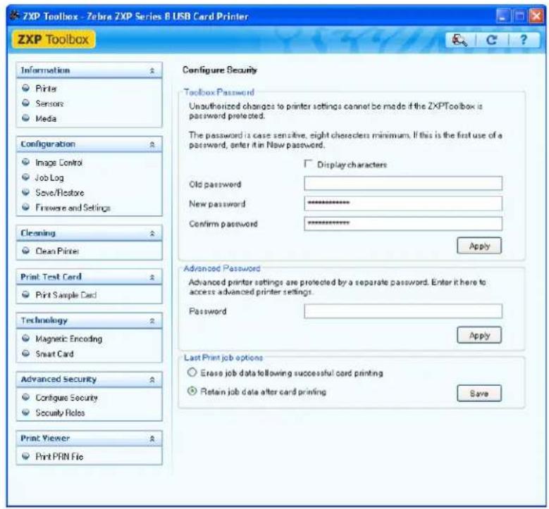
- Repeat the password in the Confirm password field.
- Click on the Apply button.
To change the Password:
- Enter your password in the Old password field.

-
Enter the new password in the New password and the Confirm password fields.
-
Click on the Apply button.
vanced Password:
This password provides access to service-related tests and adjustments via the Advanced Setting button; see Firmware and Settings on page 80. Use is limited to Zebra-authorized service personnel.
Last Print job option:
- The Erase job data following successful card printing option erases the print job after successful card printing.
- The Retain job data after card printing option allows the print job to remain in memory for multiple prints via the OCP.
The Save button saves your selection.
Establish Security Roles

Important • To manage this section, you are required to be the administrator of the local computer or have administrative privileges.
Use this section used to establish security roles; i.e., grant and restrict access to various ZXP Series Toolbox screens. The list of users in the drop-down menu (e.g., Guest, HelpAssistant, Local User, localfix, etc.) is derived from the list of users on the system.
To set security access roles:
- Select a user from the drop-down menu.

- Use the arrow buttons (>, >>, <, and <<) to make specific features available to or restrict specific features from the selected user role.
- When satisfied with the selection, click on the Save button.
At the next log in, the user will only see or have access to the features previously granted.
Print Viewer
When you print a PRN file, you print directly to the printer, bypassing computer applications and associated printer drivers. This utility can be used to ensure that your printer is working properly by isolating it from driver-related and communication-related issues.
Print PRN file

Note • Sample PRN files are stored in the following default directory/folder: C:\Documents and Settings\All Users\ZMotifLibrary
To send a PRN file to the printer:
- Click on the Browse button.
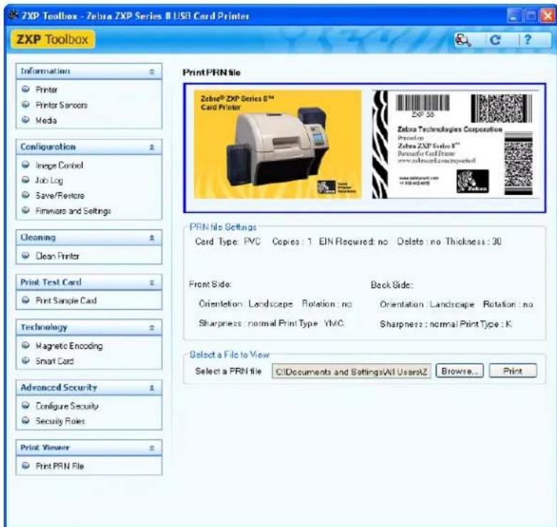
- From the Browse window, locate and select a PRN file.
- Click on the Open button.
- View the PRN file.
- When satisfied with the selection, click on the Print button.
Successfully printing the PRN file indicates that the printer and data communications to the printer are set up and configured properly.

natural_image
Technical line drawing of a mechanical device with no visible text or symbolsCaution • PROTECT YOUR FACTORY WARRANTY!

The recommended cleaning procedures must be performed to maintain your factory warranty. Other than the recommended cleaning procedures described in this manual, allow only Zebra authorized technicians to service the Printer.
NEVER loosen, tighten, adjust, bend, etc., any part or cable inside the printer.
NEVER use a high pressure air compressor to remove particles in the printer.
Cleaning the Printer
Clean your Printer using the Cleaning Cards provided. The regular use of these cards will clean and maintain important parts of your printer that cannot be reached, including the Printhead, Transport Rollers, and optional Magnetic Encoder Station.
When to Clean
• X-Roller and Y-Roller cleaning should occur every 5,000 cards.
- Heated Roller cleaning should occur every 20,000 cards. Note that a Heated Roller Cleaning Card is not supplied with the printer; order Zebra Cleaning Card Kit P/N 105999-801.
Cleaning the Rollers

Note • Do not use previously used cleaning cards.
Step 1. Initiate the cleaning process.
a. Press the MENU button on the Operator Control Panel (OCP). The OCP will display the Main Menu.
b. Scroll through the Main Menu, and select Advanced Settings. The OCP will display the Advanced Settings Menu.
c. Scroll through the Advanced Settings Menu, and select Clean Printer. The OCP will display the Clean Printer Menu.
Step 2. Clean the X-Drive Rollers.
a. Select Clean Side Card Path to run the X-Roller Cleaning Routine.
b. Use the X-Roller Cleaning Card.
c. Follow the OCP instructions.

natural_image
Technical line drawing of a mechanical device with no visible text or symbolsd. When complete, the OCP will return to the Clean Printer Menu.
Step 3. Clean the Y-Drive Rollers.
a. Select Clean Front Card Path to run the Y-Roller Cleaning Routine.
b. Use the Y-Roller Cleaning Card.
c. Follow the OCP instructions.
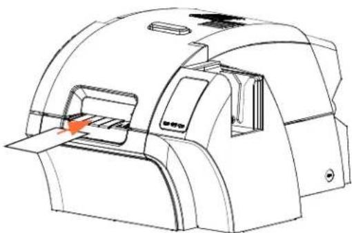
natural_image
Technical line drawing of a mechanical device with no visible text or symbolsd. When complete, the OCP will return to the Clean Printer Menu.
Step 4. Clean the Heated Rollers.
a. Select Clean Transfer Path to run the Heated Roller Cleaning Routine.
b. Use the Hot Roller Cleaning Card.
c. Follow the OCP instructions.
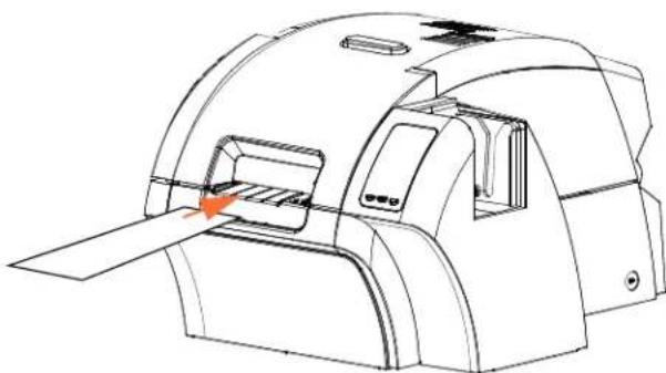
natural_image
Technical line drawing of a mechanical device with an orange arrow indicating a component or operation (no text or symbols present)d. When complete, the OCP will return to the Clean Printer Menu.
e. Then use the Heated Roller Cleaning Card to clean the Platen; see page 96.
Exit the Printer Menus by selecting RETURN at each menu level (Clean Printer Menu, Advanced Settings Menu, and Main Menu).
Cleaning the Platen
Step 1. Open the printer Door.
Step 2. Remove the Transfer Film.
Step 3. Manually run the Hot Roller Cleaning Card over the Platen.

Step 4. Re-install the Transfer Film.
Step 5. Close the printer Door.
Cleaning the Printhead
Printhead cleaning removes deposits when print anomalies persist. To avoid deposits, only use foam-tipped swabs or pens.

Caution • Never use a sharp object or any abrasive to scrape deposits from the Printhead. Permanent damage to the Printhead will result.

Caution • Do not touch the Printhead if the printer has been in service in the last 10 minutes. It could be very hot and cause a burn.
Step 1. Place the printer power switch in the OFF() position.
Step 2. Open the Door, and remove the print ribbon.
Step 3. Bend the Cleaning Swab to release the cleaning fluid.
Step 4. Clean Printhead by moving Cleaning Swab tip side-to-side across the Printhead elements. Only use moderate force. To re-order Cleaning Swabs, see the Media List on the User Documentation and Drivers CD supplied with this printer.
Step 5. Reinstall the print ribbon, and close the Door.
Step 6. Place the printer power switch in the ON() position.
Card Cleaning Cartridge
The Card Cleaning Cartridge cleans the cards entering the printer through the card feeder. To ensure print quality, the card cleaning roller requires periodic replacement. New card cleaning rollers are included with each print ribbon or may be purchased separately. (To reorder, refer to the Media List on the User Documentation and Drivers CD supplied with this printer.)
Installation of the Card Cleaning Cartridge is described in Section 2 and is not repeated in detail here.

Note • Before replacing the Card Cleaning Cartridge or its adhesive roller, clean the Printer using the Cleaning Cards as described earlier in this chapter.
Card Cleaning Roller
The Card Cleaning Roller cleans the cards entering and exiting the Transfer Station. To ensure print quality, the card cleaning roller requires periodic replacement. A new card cleaning roller is included with each print ribbon or may be purchased separately. (To reorder, refer to the Media List on the User Documentation and Drivers CD supplied with this printer.)
Installation of the Card Cleaning Roller is described in Section 2 and is not repeated in detail here.
Troubleshooting

natural_image
Abstract black and white pattern with curved white lines on a black background (no text or symbols)The table on the next page offers causes and solutions to symptoms related to improper operation. Check the table when experiencing any loss of operation or print quality.
Use the following figure in conjunction with the table to help locate the possible cause and effect a solution.

OCP Error Messages
| ERROR MESSAGE POSSIBLE CAUSE POSSIBLE SOLUTION | ||
| BOTTOM LAMINATE FEED * | ·Bottom laminate cartridge is not installed properly.·Cartridge is not removed when that side of the card is not being laminated. | ·Remove, reposition, and re-install the bottom laminate cartridge.·Remove the bottom laminate cartridge. |
| BOTTOM LAMINATE OUT * | The bottom laminate has run out. Load new roll of laminate. | |
| BOTTOM LAMINATE REGISTRATION * | ·Improperly prepared registered laminate.·Media misfeed.·Patch length improperly set.·Unexpected end of laminate roll detected. | Remove and recut laminate in the center of the index notch, re-install, and retry. |
| CARD CLEAN ERROR ·Faulty Card Cleaning Roller (if error during single card feed.·Faulty Card Cleaning Cartridge (if cards fed from Input Hopper). | Replace the Card Cleaning Roller or Card Cleaning Cartridge, as appropriate. | |
| CARD EJECT ERROR Card from previous job is stuck in the exit area. | Remove the card from the exit area. | |
| CARD FEED ERROR Card is jammed in Input Hopper. a. Clear the card jam in the Input Hopper, and re-seat the Input Hopper.b. Ensure that cards are not stuck together and that they are the correct thickness (30 - 40 mil). | ||
| CARD JAM Card is jammed in Card Transport or Transfer Station. | Check the card path:a. Idler Roller Assembly (open door).b. Transfer Station (rotate the eject roller CCW).c. Check printer-to-laminator area for a jammed card. * | |
| CARD NOT DETECTED | Card did not reach card sensor or is jammed in Input Hopper or Card Transport. | a. Clear the card jam in the Input Hopper, and re-seat the Input Hopper.b. Ensure that cards are not stuck together and that they are the correct thickness.c. Check Idler Roller Assembly (open door). |
| CARD NOT INSERTED | Card was not fed into Single Card Feed Slot within nominal 30-second period. | Retry and feed card into the Single Card Feed Slot, or cancel the operation. |
* Message only applies to Printers with a Laminator.
| ERROR MESSAGE | POSSIBLE CAUSE | POSSIBLE SOLUTION |
| CONTACT READ ERROR • Faulty card.• Incorrect card orientation.• Incorrect Mode or Protocol setting.• Faulty reader. | • Try another card.• Try another card (check orientation).• Correct the Mode or Protocol setting.• Contact Zebra Technical Support. | |
| CONTACT WRITE ERROR • Faulty card.• Incorrect card orientation.• Incorrect Mode or Protocol setting.• Faulty writer. | • Try another card.• Try another card (check orientation).• Correct the Mode or Protocol setting.• Contact Zebra Technical Support. | |
| CONTACTLESS READ ERR • Faulty card.• Incorrect Mode or Protocol setting.• Faulty reader. | • Try another card.• Correct the Mode or Protocol setting.• Contact Zebra Technical Support. | |
| CONTACTLESS WRITE ERR • Faulty card.• Incorrect Mode or Protocol setting.• Faulty writer. | • Try another card.• Correct the Mode or Protocol setting.• Contact Zebra Technical Support. | |
| COVER OPEN Door is ajar. Verify the Door is completely closed. | ||
| EP SCRIPT ERROR Internal logic error. a. Power cycle the printer. | b. Contact Zebra Technical Support. | |
| ETHERNET COMM ERROR | Ethernet communication problem. | a. Disconnect and reconnect the network cable.b. Power cycle the printer.c. Contact Zebra Technical Support. |
| FILM JAM | The transfer film is jammed. | a. Check the transfer film.b. Reinstall the transfer film.c. Repair the break in the transfer film and reinstall. |
| FILM MOTION ERROR | Transfer film not correctly responding to motion commands. | a. Check the transfer film.b. Reinstall the transfer film.c. Power cycle the printer.d. Contact Zebra Technical Support. |
| FW UPGRADE ERROR | Invalid firmware version selected. | Verify the version, and retry updating the firmware. |
| GENERAL MEMORY ERROR | There is a problem when accessing memory. | a. Power cycle the printer.b. Contact Zebra Technical Support. |
| HCB BULB ERROR | The Halogen Controller Board (HCB) is unable to pulse the upper and lower heaters to bring the upper and lower rollers to the proper temperature. | Contact Zebra Technical Support. |
| HCB SENSOR ERROR | The Halogen Controller Board (HCB) is unable to detect temperature of the upper or lower rollers. | Contact Zebra Technical Support. |
| INVALID BOTTOM LAMINATE * | Laminate does not match the type allowed in the laminator or top and/or bottom has been swapped. | a. Verify that the top and bottom laminate cassettes are installed in the correct locations.b. Verify the part number of the laminate is correct on OCP.c. Power cycle the printer. |
| INVALID CARD TYPE Encoding error. a. Ensure that you are using the correct card type.b. Ensure that the card orientation is correct for the card type.c. In the Encoding tab of the driver, check that the settings are correct for the cards you are using.d. Ensure that the data conforms to ISO Specifications.e. Retry writing and reading. | ||
| INVALID FILM Transfer film does not match the printer. a. Verify the part number of the transfer film is correct on OCP.b. Power cycle the printer. | ||
| INVALID RIBBON | Print ribbon does not match the printer. | a. Verify the part number of the print ribbon is correct on OCP.b. Power cycle the printer. |
| INVALID TOP LAMINATE * | Laminate does not match the printer. | a. Verify the part number of the laminate is correct on OCP.b. Power cycle the printer. |
| LAMINATOR BOTTOM CUTTER FAIL * | Bottom cutter has failed. Contact Zebra Technical Support. | |
| LAMINATOR BOTTOM CUTTER STALL * | Bottom cutter blade is obstructed, or bottom cutter mechanism is damaged. | Contact Zebra Technical Support. |
| LAMINATOR BOTTOM HEATER FAIL * | Bottom heater did not turn on after being instructed to do so. When the heater is enabled, the controller will wait a certain specified amount of time for it to attain the set target temperature. If the heater fails to reach the target in the specified time, the BotHeaterFail fault will be set. | a. Replace the bottom halogen bulb.b. Contact Zebra Technical Support. |
| LAMINATOR BOTTOM TEMP SENSOR FAIL * | The bottom temperature (thermopile) sensor has failed. | Contact Zebra Technical Support. |
| LAMINATOR BOTTOM TEMPERATURE HIGH * | If the bottom roller temperature ever exceeds a fixed temperature threshold, the over temp error occurs. | a. Power cycle the printer.b. Contact Zebra Technical Support. |
| LAMINATOR CARD FEED * | Printer has not fed the card far enough into laminator mechanism for infeed rollers to grab it. | Open the Laminator and printer doors to check for jammed/stuck cards |
| LAMINATOR COVER OPEN * | This warning will be displayed if the cover protecting the laminator is opened. | This warning will be cleared when the laminator cover is closed. |
* Message only applies to Printers with a Laminator.
| ERROR MESSAGE POSSIBLE | CAUSE POSSIBLE SOLUTION | |
| LAMINATOR EARLY CARD JAM * | Card did not make it to the staging rollers. | Remove the card and/or laminate that is stuck in the laminator staging/cutting area. |
| LAMINATOR EEPROM DEFAULT * | The parameters stored in EEPROM have been reset to their default values. This will not normally happen, but could be seen with certain FW upgrades when new parameters have been added by Engineering. It could also indicate a problem with the Laminator's EEPROM. | a. Press RETRY on the OCP when this error occursb. Power cycle the unit. |
| LAMINATOR FAILED INIT * A | Laminator was detected by the printer, but was unable to communicate to it. | Contact Zebra Technical Support. |
| LAMINATOR FAN FAIL * This | should only happen if one or both cooling fans fail or the cooling vents near the heated roller assembly are blocked or the fan(s) have failed. | a. Check for blocked vents.b. Contact Zebra Technical Support. |
| LAMINATOR INITIALIZING * T | This warning will be displayed after the laminator door is closed and laminate spools are re-read/detected. | No action needed. |
| LAMINATOR LATE CARD JAM * | Card did not unblock the exit sensor in the specified time. | a. Check for card jammed in the exit area.b. Assure that the sliding exit door is not partially blocking the exit path. |
| LAMINATOR MIDDLE CARD JAM * | Card and laminate have jammed inside heater assembly, often due to mis-positioned laminate patch sticking to heated rollers. | Remove the oven, and inspect for stuck cards. |
| LAMINATOR POLL TIMEOUT * | The laminator expects the printer to periodically send commands to it within a specified time period. If it fails to do so, it assumes that something is wrong with the communication link or that the printer is down. Activation of the PollTimeout fault also results in the laminator being forced into Powersave mode, and operations in progress will be halted. This error may occur if the printer-to-laminator communications is having intermittent problems. | a. Power cycle the printer.b. Contact Zebra Technical Support. |
| LAMINATOR TOP CUTTER FAIL * | Top cutter has failed. Contact Zebra Techni cal Support. | |
| LAMINATOR TOP CUTTER STALL * | Top cutter blade is obstructed, or top cutter mechanism is damaged. | Contact Zebra Technical Support. |
| LAMINATOR TOP HEATER FAIL * | Top heater did not turn on after being instructed to do so. When the heater is enabled, the controller will wait a certain specified amount of time for it to attain the set target temperature. If the heater fails to reach the target in the specified time, the TopHeaterFail fault will be set. | a. Replace the top halogen bulb.b. Contact Zebra Technical Support. |
* Message only applies to Printers with a Laminator.
| ERROR MESSAGE | POSSIBLE CAUSE | POSSIBLE SOLUTION |
| LAMINATOR TOP TEMPSENSOR FAIL * | The top temperature (thermopile) sensor has failed. | Contact Zebra Technical Support. |
| LAMINATOR TOPTEMPERATURE HIGH * | If the top roller temperature ever exceeds a fixed temperature threshold, the over temp error occurs. | a. Power cycle the printer.b. Contact Zebra Technical Support. |
| LAMINATOR UNKNOWNERROR * | An unknown error has occurred – this is an indication of a FW problem and should not occur. | Press RETRY on the OCP. |
| LAMINATOR WARMING * This | warning will be cleared when the heaters attain their temperature targets. | No action necessary. |
| MAG MOTION ERROR | Mag card positioning error encountered. | Retry writing and reading. |
| MAG READ ERROR • Encoding | error.• Defective magnetic stripe. | a. Ensure that you are using the correct card type.b. Check that the cards are loaded with the magnetic stripe in the correct orientation (normally stripe down and toward the rear of the printer).c. Ensure that the cards are set-up correctly in the printer driver (coercivity setting).d. Ensure that the data conforms to ISO Specifications.e. Retry reading. |
| MAG WRITE ERROR • Encoding | error.• Defective magnetic stripe. | a. Ensure that you are using the correct card type.b. Check that the cards are loaded with the magnetic stripe in the correct orientation (normally stripe down and toward the rear of the printer).c. Ensure that the cards are set-up correctly in the printer driver (coercivity setting).d. Ensure that the data conforms to ISO Specifications.e. Retry writing. |
| MISSING HCB There is a problem with the HCB(Halogen Controller Board). | a. Power cycle the printer.b. Contact Zebra Technical Support. | |
| MISSING LAMINATORMAG * | An error occurred when trying to communicate to the Laminator MAB (Media Authentication Board). | a. Power cycle the printer.b. Contact Zebra Technical Support. |
| MISSING MAB An error occurred when reading the RFID Tag by the MAB (Media Authentication Board). | a. Check print ribbon orientation.b. Verify part number of the print ribbon.c. Power cycle the printer.d. Contact Zebra Technical Support. | |
* Message only applies to Printers with a Laminator.
| ERROR MESSAGE | POSSIBLE CAUSE | POSSIBLE SOLUTION |
| MOTOR VOLTAGE ERROR In | correct voltage detected at one or several motors in the unit. | a. Power cycle the printer.b. Contact Zebra Technical Support. |
| NO MAG STRIPE Mag stripe not detected. a. Ensure that you are using the correct card type.b. Check that the cards are loaded with the magnetic stripe in the correct orientation (normally stripe down and toward the rear of the printer). | ||
| OUT OF CARDS • The Input Hopper is empty.• Card is stuck in Input Hopper. | a. Load cards into the Input Hopper.b. Re-seat the Input Hopper. | |
| OUT OF FILM The transfer film has run out. Load new roll of transfer film. | ||
| OUT OF RIBBON The print ribbon has run out. Load a new roll of print ribbon. | ||
| PRINTHEAD MOTION ERR Printhead did not move to proper position during initialization. | a. Power cycle the printer.b. Contact Zebra Technical Support. | |
| PRINTHEAD TOO COLD | Printhead temperature out of proper range (COLD). | Turn off power, and contact Zebra Technical Support. |
| PRINTHEAD TOO HOT | Printhead temperature out of proper range (HOT). | Turn off power, and contact Zebra Technical Support. |
| REJECT ERROR | A problem during the reject process. | Contact Zebra Technical Support. |
| RIB COLOR DETECT ERR | Print ribbon is not installed correctly. | Reinstall the print ribbon. |
| RIBBON ADC ERROR | Possible hardware issue. | Contact Zebra Technical Support. |
| RIBBON BEMF ERROR | Problem with the Back EMF (BEMF) of the ribbon motors. | Contact Zebra Technical Support. |
| RIBBON JAM | The print ribbon is jammed. | a. Check the print ribbon.b. Reinstall the print ribbon.c. Repair the break in the print ribbon and reinstall. |
| RIBBON MOTION ERROR | Ribbon not correctly responding to motion commands. | a. Check the print ribbon.b. Reinstall the print ribbon.c. Repair the break in the print ribbon and reinstall. |
| ROLLERS OVER TEMP | Heated Rollers (used to transfer the image from the transfer film to the Card) are too hot for proper operation. | Turn off power, and contact Zebra Technical Support. |
| ROLLERS UNDER TEMP | Heated Rollers (used to transfer the image from transfer film to Card) are not hot enough for proper operation. | Turn off power, and contact Zebra Technical Support. |
| SMARTCARD POS ERROR | Faulty card.Incorrect card orientation.Card feed error.Mechanical alignment issue. | Try another card.Try another card (check orientation).Check card path.Contact Zebra Technical Support. |
| SYSTEM ERROR Internal logic error. a. Power cycle the printer. | b. Contact Zebra Technical Support. | |
| SYSTEM NOT READY A problem was detected during printer start-up. | a. Power cycle the printer.b. Contact Zebra Technical Support. | |
| TOP LAMINATE FEED * Top laminate cartridge is not installed properly.Cartridge is not removed when that side of the card is not being laminated.A mis-cut piece of laminate (rare) is obscuring the media sensor. | Remove, reposition, and re-install the top laminate cartridge.Remove the top laminate cartridge.Remove the mis-cut piece of laminate. | |
| TOP LAMINATE OUT * The top laminate has run out. Load new roll of laminate. | ||
| TOP LAMINATE REGISTRATION * | Improperly prepared registered laminate.Media misfeed.Patch length improperly set.Unexpected end of laminate roll detected. | Remove and recut laminate in the center of the index notch, re-install, and retry. |
| TRANSFER ERROR A problem was detected during the transfer process (print ribbon to film). | Contact Zebra Technical Support. | |
* Message only applies to Printers with a Laminator.
OCP Test Card Images
See detailed Test Card descriptions on the following page.
 Mid Gray Grid On Gray Cyan Stripes Mid Gray Grid On Gray Cyan Stripes |  |  |
 2 Pixel Grid Mid Magenta Dark Cyan 2 Pixel Grid Mid Magenta Dark Cyan | 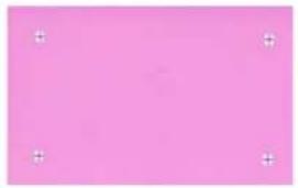 |  |
 Max Gray Offset Dots Smear Max Gray Offset Dots Smear |  |  |
 Min Magenta White Max-Gray Max-Gray White Min Magenta White Max-Gray Max-Gray White | 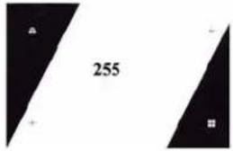 |  |
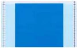 Motion & Registration Gradient Boxes Density Setup Motion & Registration Gradient Boxes Density Setup |  |  |
 Grid On Gray 2 Grid On Gray 2 | ||
Test Card Descriptions
| Image | Description Print artifacts to look for with this image | ||
 | Mid Gray Flat uniform gray Motion artifacts, banding, platen defects, transfer artifacts, dirt, overall density level | ||
 | Grid On Gray Solid black on top, gray grid underneath | Colored ribbon wrinkles in the black area, or clear/white transfer film wrinkles in the gray area | |
 | Cyan Stripes Horizontal cyan stripes alongside vertical lighter cyan box | Non-uniformity or horizontal banding within cyan box on right of card | |
 | 2 Pixel Grid 2 pixel wide grid lines on white | Mis-registration between color planes | |
 | Mid Magenta Flat uniform mid-density magenta | Motion artifacts, banding, platen defects, density level, uniformity | |
 | Dark Cyan Maximum cyan only density image | Motion artifacts, transfer artifacts, scratches, dirt | |
 | Max Gray Maximum CMY (black) density image | Wrinkles, snapping noise during printing, ribbon /transfer-film tears or breaks, flash, card positioning | |
 | Offset Dots Individual C, M, and Y dots spaced at regular intervals | Motion artifacts on specific color planes, mis-registration | |
 | Smear | Gray with full density YMCK blocks near top | Color smear artifacts |
 | Min Magenta Flat uniform low-density magenta | Motion artifacts, banding, platen defects, density level, uniformity, bead position | |
 | White Max-Gray | Max-density areas on sides with tilted white center | Ribbon wrinkle |
 | Max-Gray White | Same as above with slant direction changed | Ribbon wrinkle |
 | Motion & Registration | Uniform cyan with registration marks on sides | Banding, mis-registrations, motion artifacts |
 | Gradient Boxes | 3 sets of light-to-dark grayscale ramps | Used to create color calibration look-up table |
 | Density Setup | Used to measure mid and max densities | Density level of mid-gray and black |
 | Grid On Gray 2 | Less stressful version of the grid-on-gray target | Colored ribbon wrinkles in the black area, or clear/white transfer film wrinkles in the gray area |
Ethernet Issues
If both LEDs are off, the printer has not detected the presence of a network cable. To solve the problem:
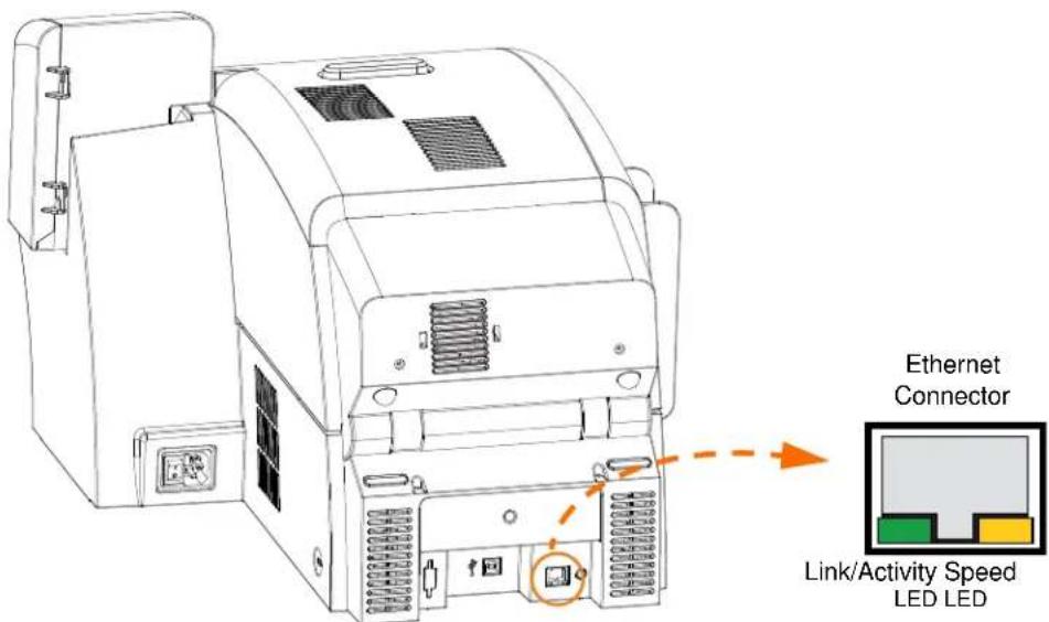
- Verify that the network cable is appropriate and has an RJ-45 connector.
- Remove the network cable from the printer. Plug the network cable back in until you hear a positive click. Check the other end of the cable in the same manner. If the printer still does not detect a cable, then continue.
- Connect the printer to a known good network. If the printer is still unable to detect the network cable, contact Technical Support for assistance.

natural_image
Technical line drawing of a mechanical device with no visible text or symbolsTechnical Specifications

natural_image
Abstract black and white pattern with curved white lines on a black background (no text or symbols)Standard Features
• Thermal transfer and dye diffusion to transfer film
• Full color or monochrome reverse transfer printing
- Single- and dual-sided printing
• Maximum print speed (batch mode; i.e., the same image repeatedly)
- Single-sided (Front Only)
YMC 190 cph
YMCK
160
cph
- Dual-sided (Front and Back) YMCK (YMC Front, K Back) 170 cph YMCKK (YMCK Front, K Back) 150 cph
• Photo quality image
• Over-the-edge printing on standard CR80 media
- Microsoft Windows Certified drivers
- Single-card feed capability
• 150 card capacity feeder (30 mil)
• 15 card reject hopper (30 mil)
• 100 card output hopper (30 mil)
• i Series™ intelligent media technology
• Auto calibration of media
• 21-character soft menu LCD text operator display
• 304 dpi (12.0 dots/mm) print resolution
- 64MB memory standard
- 2-year unlimited warranty on printer, lifetime limited warranty on printhead with Genuine Zebra Supplies
Specifications
Encoding Options
- Smart card contact encoder – ISO 7816, PC/SC Compliant
- Magnetic stripe encoder – ISO 7811 and JIS-II (new and re-encoded; tracks 1, 2, and 3; high and low coercivity; stripe down; 30 - 40 mil card thickness)
- Contact smart card encoder – EMV level 1 certified
• ISO 14443 MIFARE (13.56 MHz) and ISO 7816 contact encoder combo
Communications Interfaces
- USB V2.0 / 1.1 protocol
- USB supports plug-n-play printer identification
- USB and internal 10/100 Ethernet (Standard)
Software
Microsoft Windows Certified Printer Drivers Supported
- Windows XP*, Windows Vista*, Windows 7*, Windows Server 2003* *32-bit and 64-bit certified
Driver Features
- Graphical card orientation setting to visualize card printing setup and configuration
- Card type setting eliminates unnecessary setup and configuration settings
- Complete graphical control over area and element selection of black extraction parameters insures true black and color printing exactly where you want it on the card
• Auto sensing of print ribbon type - Optional driver password protection setting to prevent accidental or unauthorized printer configuration changes
ZXP Toolbox
- Printer configuration tools and utilities for complete control over all printer functions and features
- User role-based features enables true security printer operations
- Complete technology card management enables setup and testing of all printer and encoder features and functionality
- Printer test cards and diagnostics utilities ensure error free printing and fast troubleshooting capabilities
Card Compatibility
- Card Thickness: 30 – 40 mil
• Card Size: ISO 7810 format, Type ID-1, CR-80 - Card Material: ABS; PVC, Composite; TESLIN, Composite; PET; PETG; Polycarbonate; PVC
Agency Approvals
Zebra ZXP Series 8 Card Printer complies with following applicable directives and standards for the ITE: Residential, Commercial & Light Industry environments
• For US/Canada/Mexico/Australia&NZ
• FCC Class A, cfr47, Part 15 Subpart J
• FCC 15.257 2008, Part15 Subpart C
• Canadian STD RSS-210
• NOM-ETL (Mexico)
• EN60950: 2000 Safety Standard (TUV & RTL)
• C-Tick (Australia) Electromagnetic Radiation Standard
• F o r E u r o p e :
- Applicable Directives and Supporting Standards:
2004/108/EC EMC Directive, EN55022:2006 Class A, EN55024:1998+AD1:2001+AD2:2003, EN61000-3-2:2006, EN61000-3-3:1995+AD1:2001, 2006/95/EC LVD Directive, EN60950-1:2001, CB Scheme
- WLAN Enabled
Applicable Directives and Supporting Standards:
99/5/EC R&TTE Directive, EN 301 489-17 V1.2.1 (2002-08), EN 300 328 V1.7.1 (2006-10)
• RFID Enabled
Applicable Directives and Supporting Standards:
99/5/EC R&TTE Directive, EN 301 489-3 V1.4.1 (2002-08), EN 300 220-2 V2.1.2 (2007-06)
Technical Specifications
Specifications
Electrical
• Auto-switching Single-phase AC power
- 90V\~264V AC RMS and 47-63 HZ (50-60 Hz nominal)
• Power consumption:
Idle 100 W
Printing 150 W
Initializing / Warm-up 300 W
Sleep 20 W
Physical
• Height (printer only) 11.9" (303 mm)
• Height (with card feeder) 13.2" (336 mm)
- Width 14" (356 mm)
- Width (with card feeder) 14.9" (379 mm)
- Depth 20.4" (519 mm)
• Weight (printer only) 27.5 lbs (12.5 kg)
Environmental
- Operating Temperature 59^ to 77^ (15° to 25°C)
- Storage Temperature 23^ to 131^ (-5^ to 55^)
- Operating Humidity 20% to 80% non-condensing
• Storage Humidity 10% to 90% non-condensing - Shipping Temperature -40° to 140°F (-40° to 60°C)
- Shipping Humidity 10 to 90% non-condensing
Declarations of Conformity
ZEBRA TECHNOLOGIES CORPORATION
Declares that the following Information Technology Equipment
Zebra ZXP Series 8 Card Printer
complies with following applicable directives and standards for the
ITE: Residential, Commercial & Light Industry environments
CE
Applicable Directives and Supporting Standards:
2004/108/EC EMC Directive, EN55022:2006 Class A,
EN55024:1998+AD1:2001+AD2:2003EN, 61000-3-2:2006, EN61000-3-3:1995+AD1:2001,
2006/95/EC LVD Directive, EN60950-1:2001, CB Scheme
RFID Enabled
Applicable Directives and Supporting Standards:
99/5/EC R&TTE Directive, EN 301 489-3 V1.4.1 (2002-08), EN 300 220-2 V2.1.2 (2007-06)
For a formal certificate, please contact the Compliance Office at Zebra's Camarillo facility.
EUROPE: Norway Only: This product is also designed for IT power system with phase to phase voltage 230V. Earth grounding is via the polarized, 3-wire power cord.
The Zebra ZXP Series 8 Card Printer has been tested and found to comply with the limits for a Class A digital device, pursuant to Part 15 of the FCC Rules. These limits are designed to provide reasonable protection against harmful interference when the equipment is operated in a commercial environment. This equipment generates, uses, and can radiate radio frequency energy and, if not installed and operated in accordance with the Zebra ZXP Series 8 Card Printer User's Manual, may cause harmful interference to radio communications. Operation of this equipment in a residential area is likely to cause harmful interference in which case the user will be required to correct the interference at his own expense.
Pursuant to Part 15.21 of the FCC Rules, any changes or modifications to this equipment not expressly approved by Zebra may cause harmful interference and void the FCC authorization to operate this equipment.
FCC Radiation Exposure Statement (applicable to 15.247 device only)
This equipment complies with FCC radiation exposure limits set forth for an uncontrolled environment. This equipment should be installed and operated with minimum 20 cm between the radiator and your body. This transmitter must not be collocated or operating in conjunction with any other antenna or transmitter unless authorized to do so by the FCC.
Industry Canada Notice
This device complies with Industry Canada ICES-003 class A requirements.
Japan: Ministry of Internal Affairs and Communications (MIC) Certification
This product has received MIC approval.
Approval number is No. AC-xxxxx
This equipment generates, uses, and can radiate radio frequency energy and, if not installed and operated in accordance with the User's Manual, may cause harmful interference to radio communications or medical instruments such as a pacemaker.
APPENDIX A
Printer Configurations

natural_image
Abstract black and white pattern with curved black and white shapes (no text or symbols)Introduction
The Part Number of a particular printer is shown on a label affixed to the bottom of the printer; that Part Number identifies the specific configuration for that printer. The chart on the following page shows the configurations that are available.
Part Numbers
| PART NUMBER DESCRIPTION | ||
| z 8 _ | Base Unit | |
| _ 1 _ 2 | - _ - - - - - - - - - - - - - - - - - - - - - - - - - - - - - - - - - - - - - - - - - - - - - - - - - - - - - - - - - - - - - - - - - - - - - - - - - - - - - - - - - - - - - - - - - - - - - - - - - - - - | Single-Sided PrintingDual-Sided Printing |
| _ - - _ - - - - - - - - - - - - - - - - - - - - - - - - - - - - - - - - - - - - - - - - - - - - - - - - - - - - - - - - - - - - - - - - - - - - - - - - - - - - - - - - - - - - - - - - - - - - - - - - - - | - 0 _ - - - - - - - - - - - - - - - - - - - - - - - - - - - - - - - - - - - - - - - - - - - - - - - - - - - - - - - - - - - - - - - - - - - - - - - - - - - - - - - - - - - - - - - - - - - - - - - - - - 0 _ - - - - - - - - - - - - - - - - - - - - - - - - - - - - - - - - - - - - - - - - - - - - - - - - - - - - - - - - - - - - - - - - - - - - - - - - - - - - - - - - - - - - - - - - - - - - - - - - | Smart Card OptionsNoneContact Encoder + Contactless MIFAREContact Station |
| _ - - _ - - - - - - - - - - - - - - - - - - - - - - - - - - - - - - - - - - - - - - - - - - - - - - - - - - - - - - - - - - - - - - - - - - - - - - - - - - - - - - - - - - - - - - - - - - - - | - 0 _ - - | |
| _ - - _ - - - - - - - - - - - - - - - - - - - - - - - - - - - - - - - - - - - - - - - - - - - - - - - - - - - - - - - - - - - - - - - - - - - - - - - - - - - - - | - M _ - - | |
| _ - - _ - - - - - - - - - - - - - - - - - - - - - - - - - - - - - - - - - - - - - - - - - - - - - - - - - - - - - - - - - - - - - - - - - - - - - - - - - - | - 0 _ - | |
| _ - - _ - - - - - - - - - - - - - - - - - - - - - - - - - - - - - - - - - - - - - - - - - - - - - - - - - | - A _ | |
| _ - - _ - | InterfaceUSB and 10/100 Ethernet | |
| _ - - _ - | Software/KitNoneMedia Starter Kit (includes: 1 YMCK ribbon kit, 1 roll of InTM, 200 PVC cards) | |
| _ - - _ | MiscellaneousNoneMade in America | |
| _ - - _ | Custom CodeReserved for future options | |
| _ - - _ | Custom CodeReserved for future options | |
Appendix B
Setting Custom Card Specifications

natural_image
Abstract black and white pattern with curved white lines on a black background (no text or symbols)B.1 Introduction
This document is to be used for setting the specifications for cards not listed in the Card type in use dropdown menu; circled below. Setting the specifications for a non-listed card type is a three-step process that uses the Card Setup Tab:

Note • To access the Card Setup Tab, select Start > Printers and Faxes. Right click on the Zebra ZXP Series 8 Card Printer listing; and select Printing Preferences > Card Setup.
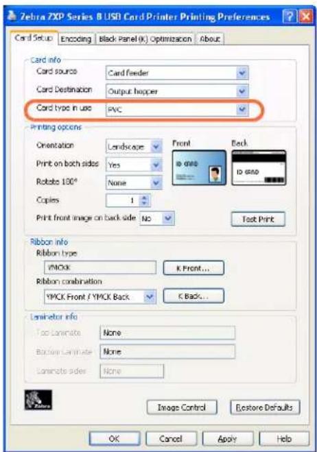
B.2 Process Flowchart

flowchart
graph TD
    A["start"] --> B["select card type"]
    B --> C["print card"]
    C --> D["examine card"]
    D --> E{partial transfer?}
    E -->|yes| F["adjust transfer temperature"]
    E -->|no| G{warpage?}
    G -->|yes| H["adjust transfer temperature"]
    G -->|no| I{card indentation?}
    H --> J["adjust transfer speed"]
    I --> K{flash?}
    K -->|yes| L["adjust transfer temperature"]
    K -->|no| M["stop"]
    L --> N["adjust transfer speed"]
    F --> O["Section B.4.2"]
    H --> P["Section B.4.3"]
    J --> Q["Section B.4.4"]
    N --> R["Section B.4.5 and Section B.4.6"]
    O --> S["Section B.4.2"]
    P --> T["Section B.4.3"]
    Q --> U["Section B.4.5 and Section B.4.6"]
B.3 3-Step Process
Step 1: Select the Card Type
From the Card type in use dropdown menu, select Custom 1 or Custom 2; and click OK. Note that Custom 1 or Custom 2 have adjustable transfer temperature and transfer speed tables; the other card types do not.


Setting Custom Card Specifications
3-Step Process
Step 2: Make adjustments

Note • Before making any adjustments, print and examine a test card (Step 3:). The quality of the test card will determine whether or not to continue the process.
After selecting Custom 1 or Custom 2, the Card Specifications window will appear. Make the recommended transfer temperature and/or transfer speed adjustment (Section B.4), and click OK.
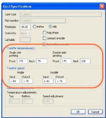
The Card Specifications window will close.
Step 3: Print and examine Test Card
From the Card Setup tab, print (click on the Test Print button circled below) and examine a test card.
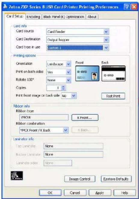
The quality of the test card will determine whether or not to continue the process.

Setting Custom Card Specifications
Adjustments
B.4 Adjustments
Problems addressed in this section include:
B.4.2 Partial Transfer.... 126
Front of card.... 126
Back of card.... 129
B.4.3 Warpage.... 132
Edges curled down 132
Edges curled up 135
Irregular Warpage 138
B.4.4 Card Indentation.... 142
B.4.5 Flash 146
Side Edge 146
Leading Edge.... 149
B.4.6 Special Cases.... 151
Flash on Smart Card Chip 151
Flash on Magnetic Stripe 155
Excess Leading-Edge Flash on Mag Cards.... 159
B.4.1 Adjustment Overview
When making adjustments, be aware that interdependencies exist between parameters; e.g., to fix the upward warpage, the first step is to decrease the front side transfer temperatures; but this could affect the partial transfer and possibly the flash.
To compensate for interdependency issues, adjust the parameters in the following order:
Step 1. Start by correcting any partial transfer issues using the same procedure outlined in Section B.4.2.
Step 2. Then attempt to improve warpage (Section B.4.3) and indentations (Section B.4.4). Start with the acceptable settings from Step 1. While adjusting parameters, ensure that the transfer quality remains acceptable. Do not continue reducing temperatures or increasing speeds if the transfer quality becomes unacceptable.
Step 3. Then attempt to improve flash (Section B.4.5). Start with the acceptable settings from Step 2. While adjusting parameters, ensure transfer and warpage remain acceptable.

Setting Custom Card Specifications
Adjustments
B.4.2 Partial Transfer
natural_image
Illustration of a zebra with rainbow-colored stripes, standing in front of zebra silhouettes (no text or symbols)Light or missing transfer on the sides
natural_image
Illustration of a zebra with rainbow-colored stripes, no text or symbols presentSpotty transfer anywhere on the card

natural_image
Illustration of zebra silhouettes with a rainbow-colored striped pattern on their backs (no text or symbols)Light transfer on entire card
Front of card
Partial transfer is usually caused by lack of energy being transferred to the card, i.e. the temperatures are too low or the speeds are too fast.
Step 1. Increase Front Transfer Temperature:
a. From the Card Specifications window, make a note of the default front transfer temperature settings; see Section B.3.
b. Increase the appropriate (single or double side) front transfer temperature by 5.
c. Click on the OK button.

d. Print a test card; see Section B.3.
e. Examine the test card.
- If there is noticeable improvement, continue increasing the front transfer temperature by 5, printing a test card, and examining the resulting card. Stop when the problem is corrected or there is no more improvement. If the problem is corrected, no more adjustment is required; otherwise go to Step 2.
- If there is no noticeable improvement, return the temperature to its default setting; and go to Step 2.
Step 2. Decrease Transfer Input Speed
a. From the Card Specifications window, make a note of the default transfer input speed settings.
b. Decrease the appropriate (single or double) transfer input speed by 0.2.
c. Click on the OK button.
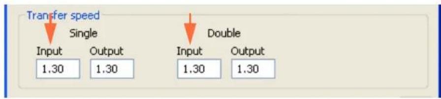
d. Print a test card.
e. Examine the test card.
- If there is noticeable improvement, continue decreasing the transfer input speed by 0.2, printing a test card, and examining the resulting card. Stop when the problem is corrected or there is no more improvement. If the problem is corrected, no more adjustment is required; otherwise go to Step 3.
- If there is no noticeable improvement, return the speed to its default setting; and go to Step 3.

Setting Custom Card Specifications
Adjustments
Step 3. Decrease Transfer Output Speed
a. From the Card Specifications window, make a note of the default transfer output speed settings.
b. Decrease the appropriate (single or double) transfer output speed by 0.2.
c. Click on the OK button.

d. Print a test card.
e. Examine the test card.
- If there is noticeable improvement, continue decreasing the transfer output speed by 0.2, printing a test card, and examining the resulting card. Stop when the problem is corrected or there is no more improvement. If the problem is corrected, no more adjustment is required. If the problem persists, contact Zebra Technical Support.
- If there is no noticeable improvement, return the transfer output speed to its default setting; and contact Zebra Technical Support.
Back of card
Partial transfer is usually caused by lack of energy being transferred to the card, i.e. the temperatures are too low or the speeds are too fast.
Step 1. Increase Back Transfer Temperature:
a. From the Card Specifications window, make a note of the default back transfer temperature settings; see Section B.3.
b. Increase the appropriate (single or double side) back transfer temperature by 5.
c. Click on the OK button.

d. Print a test card; see Section B.3.
e. Examine the test card.
- If there is noticeable improvement, continue increasing the back transfer temperature by 5, printing a test card, and examining the resulting card. Stop when the problem is corrected or there is no more improvement. If the problem is corrected, no more adjustment is required; otherwise go to Step 2.
- If there is no noticeable improvement, return the temperature to its default setting; and go to Step 2.

Setting Custom Card Specifications
Adjustments
Step 2. Decrease Transfer Input Speed
a. From the Card Specifications window, make a note of the default transfer input speed settings.
b. Decrease the appropriate (single or double) transfer input speed by 0.2.
c. Click on the OK button.

d. Print a test card.
e. Examine the test card.
- If there is noticeable improvement, continue decreasing the transfer input speed by 0.2, printing a test card, and examining the resulting card. Stop when the problem is corrected or there is no more improvement. If the problem is corrected, no more adjustment is required; otherwise go to Step 3.
- If there is no noticeable improvement, return the speed to its default setting; and go to Step 3.
Step 3. Decrease Transfer Output Speed
a. From the Card Specifications window, make a note of the default transfer output speed settings.
b. Decrease the appropriate (single or double) transfer output speed by 0.2.
c. Click on the OK button.

d. Print a test card.
e. Examine the test card.
- If there is noticeable improvement, continue decreasing the transfer output speed by 0.2, printing a test card, and examining the resulting card. Stop when the problem is corrected or there is no more improvement. If the problem is corrected, no more adjustment is required. If the problem persists, contact Zebra Technical Support.
- If there is no noticeable improvement, return the transfer output speed to its default setting; and contact Zebra Technical Support.

Setting Custom Card Specifications
Adjustments
B.4.3 Warpage
Edges curled down
Warpage is usually caused by too much energy being transferred to the card; i.e., the temperatures are too hot or the speeds are too slow.

natural_image
Illustration of a rectangular electronic device with an orange logo and curved base (no text or symbols)Step 1. Decrease Back Transfer Temperature:
a. Go to the Card Specifications window; see Section B.3.
b. Make a note of the default back transfer temperature settings.
c. Decrease the appropriate (single or double side) back transfer temperature by 5.
d. Click on the OK button.

e. Print a test card; see Section B.3.
f. Examine the test card.
- If there is noticeable improvement, continue decreasing the back transfer temperature by 5, printing a test card, and examining the resulting card. Stop when the problem is corrected or there is no more improvement. If the problem is corrected, no more adjustment is required; otherwise go to Step 2.
- If there is no noticeable improvement, return the temperature to its default setting; and go to Step 2.
Step 2. Increase Front Transfer Temperature:
a. From the Card Specifications window, make a note of the default front transfer temperature settings.
b. Increase the appropriate (single or double side) front transfer temperature by 5.
c. Click on the OK button.
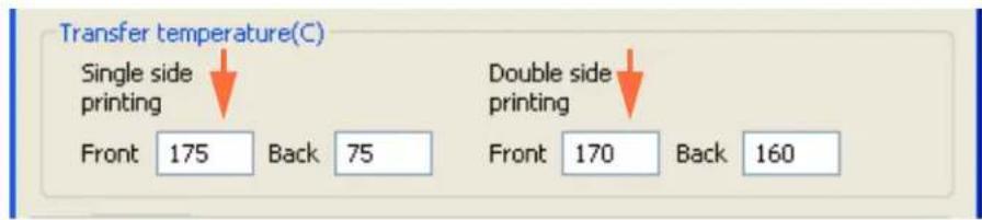
d. Print a test card.
e. Examine the test card.
- If there is noticeable improvement, continue increasing the front transfer temperature by 5, printing a test card, and examining the resulting card. Stop when the problem is corrected or there is no more improvement. If the problem is corrected, no more adjustment is required; otherwise go to Step 3.
- If there is no noticeable improvement, return the temperature to its default setting; and go to Step 3.

Setting Custom Card Specifications
Adjustments
Step 3. Increase Transfer Output Speed
a. From the Card Specifications window, make a note of the default transfer output speed settings.
b. Increase the appropriate (single or double) transfer output speed by 0.2.
c. Click on the OK button.

d. Print a test card.
e. Examine the test card.
- If there is noticeable improvement, continue increasing the transfer output speed by 0.2, printing a test card, and examining the resulting card. Stop when the problem is corrected or there is no more improvement. If the problem is corrected, no more adjustment is required. If the problem persists, contact Zebra Technical Support.
- If there is no noticeable improvement, return the transfer output speed to its default setting; and contact Zebra Technical Support.
Edges curled up
Warpage is usually caused by too much energy being transferred to the card, i.e. the temperatures are too hot or the speeds are too slow.

natural_image
Illustration of a rectangular electronic device with an orange logo on its side (no text or symbols)Step 1. Decrease Front Transfer Temperature:
a. Go to the Card Specifications window; see Section B.3.
b. Make a note of the default front transfer temperature settings.
c. Decrease the appropriate (single or double side) front transfer temperature by 5.
d. Click on the OK button.

e. Print a test card; see Section B.3.
f. Examine the test card.
- If there is noticeable improvement, continue decreasing the front transfer temperature by 5, printing a test card, and examining the resulting card. Stop when the problem is corrected or there is no more improvement. If the problem is corrected, no more adjustment is required; otherwise go to Step 2.
- If there is no noticeable improvement, return the temperature to its default setting; and go to Step 2.

Setting Custom Card Specifications
Adjustments
Step 2. Increase Back Transfer Temperature:
a. From the Card Specifications window, make a note of the default back transfer temperature settings.
b. Increase the appropriate (single or double side) back transfer temperature by 5.
c. Click on the OK button.
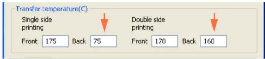
d. Print a test card.
e. Examine the test card.
- If there is noticeable improvement, continue increasing the back transfer temperature by 5, printing a test card, and examining the resulting card. Stop when the problem is corrected or there is no more improvement. If the problem is corrected, no more adjustment is required; otherwise go to Step 3.
- If there is no noticeable improvement, return the temperature to its default setting; and go to Step 3.
Step 3. Increase Transfer Output Speed
a. From the Card Specifications window, make a note of the default transfer output speed settings.
b. Increase the appropriate (single or double) transfer output speed by 0.2.
c. Click on the OK button.
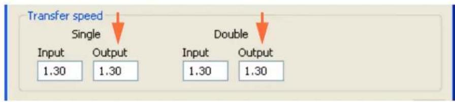
d. Print a test card.
e. Examine the test card.
- If there is noticeable improvement, continue increasing the transfer output speed by 0.2, printing a test card, and examining the resulting card. Stop when the problem is corrected or there is no more improvement. If the problem is corrected, no more adjustment is required. If the problem persists, contact Zebra Technical Support.
- If there is no noticeable improvement, return the transfer output speed to its default setting; and contact Zebra Technical Support.

Setting Custom Card Specifications
Adjustments
Irregular Warpage

Note • Irregular warpage is more common with Smart Cards.
Warpage is usually caused by too much energy being transferred to the card, i.e. the temperatures are too hot or the speeds are too slow.

natural_image
Two identical gray rectangular electronic devices with orange labels, shown from different angles (no text or symbols on the devices themselves)Step 1. Decrease Front Transfer Temperature:
a. Go to the Card Specifications window; see Section B.3.
b. Make a note of the default front transfer temperature settings.
c. Decrease the appropriate (single or double side) front transfer temperature by 5.
d. Click on the OK button.

e. Print a test card; see Section B.3.
f. Examine the test card.
- If there is noticeable improvement, continue decreasing the front transfer temperature by 5, printing a test card, and examining the resulting card. Stop when the problem is corrected or there is no more improvement. If the problem is corrected, no more adjustment is required; otherwise go to Step 2.
- If there is no noticeable improvement, return the temperature to its default setting; and go to Step 2.
Step 2. Decrease Back Transfer Temperature:
a. Go to the Card Specifications window.
b. Make a note of the default back transfer temperature settings.
c. Decrease the appropriate (single or double side) back transfer temperature by 5.
d. Click on the OK button.
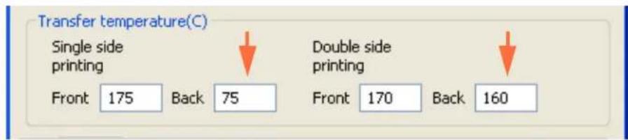
e. Print a test card.
f. Examine the test card.
- If there is noticeable improvement, continue decreasing the back transfer temperature by 5, printing a test card, and examining the resulting card. Stop when the problem is corrected or there is no more improvement. If the problem is corrected, no more adjustment is required; otherwise go to Step 3.
- If there is no noticeable improvement, return the temperature to its default setting; and go to Step 3.

Setting Custom Card Specifications
Adjustments
Step 3. Increase Transfer Output Speed
a. From the Card Specifications window, make a note of the default transfer output speed settings.
b. Increase the appropriate (single or double) transfer output speed by 0.2.
c. Click on the OK button.

d. Print a test card.
e. Examine the test card.
- If there is noticeable improvement, continue increasing the transfer output speed by 0.2, printing a test card, and examining the resulting card. Stop when the problem is corrected or there is no more improvement. If the problem is corrected, no more adjustment is required; otherwise go to Step 4.
- If there is no noticeable improvement, return the transfer output speed to its default setting; and go to Step 4.
Step 4. Increase Transfer Input Speed
a. From the Card Specifications window, make a note of the default transfer input speed settings.
b. Increase the appropriate (single or double) transfer input speed by 0.2.
c. Click on the OK button.

d. Print a test card.
e. Examine the test card.
- If there is noticeable improvement, continue increasing the transfer input speed by 0.2, printing a test card, and examining the resulting card. Stop when the problem is corrected or there is no more improvement. If the problem is corrected, no more adjustment is required. If the problem persists, contact Zebra Technical Support.
- If there is no noticeable improvement, return the transfer input speed to its default setting; and contact Zebra Technical Support.

Setting Custom Card Specifications
Adjustments
B.4.4 Card Indentation
Indentations are usually caused by too much energy being transferred to the card, i.e. the temperatures are too hot or the speeds are too slow.

natural_image
3D rendered image of a rectangular electronic device with an orange square logo and a dashed circular outline (no text or symbols)Step 1. Decrease Front Transfer Temperature:
a. Go to the Card Specifications window; see Section B.3.
b. Make a note of the default front transfer temperature settings.
c. Decrease the appropriate (single or double side) front transfer temperature by 5.
d. Click on the OK button.

e. Print a test card; see Section B.3.
f. Examine the test card.
- If there is noticeable improvement, continue decreasing the front transfer temperature by 5, printing a test card, and examining the resulting card. Stop when the problem is corrected or there is no more improvement. If the problem is corrected, no more adjustment is required; otherwise go to Step 2.
- If there is no noticeable improvement, return the temperature to its default setting; and go to Step 2.
Step 2. Decrease Back Transfer Temperature:
a. Go to the Card Specifications window.
b. Make a note of the default back transfer temperature settings.
c. Decrease the appropriate (single or double side) back transfer temperature by 5.
d. Click on the OK button.

e. Print a test card.
f. Examine the test card.
- If there is noticeable improvement, continue decreasing the back transfer temperature by 5, printing a test card, and examining the resulting card. Stop when the problem is corrected or there is no more improvement. If the problem is corrected, no more adjustment is required; otherwise go to Step 3.
- If there is no noticeable improvement, return the temperature to its default setting; and go to Step 3.

Setting Custom Card Specifications
Adjustments
Step 3. Increase Transfer Output Speed
a. From the Card Specifications window, make a note of the default transfer output speed settings.
b. Increase the appropriate (single or double) transfer output speed by 0.2.
c. Click on the OK button.

d. Print a test card.
e. Examine the test card.
- If there is noticeable improvement, continue increasing the transfer output speed by 0.2, printing a test card, and examining the resulting card. Stop when the problem is corrected or there is no more improvement. If the problem is corrected, no more adjustment is required; otherwise go to Step 4.
- If there is no noticeable improvement, return the speed to its default setting; and go to Step 4.
Step 4. Increase Transfer Input Speed
a. From the Card Specifications window, make a note of the default transfer input speed settings.
b. Increase the appropriate (single or double) transfer input speed by 0.2.
c. Click on the OK button.
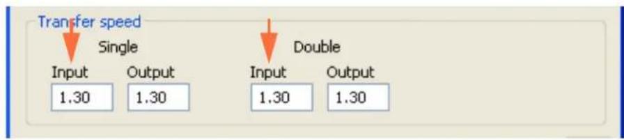
d. Print a test card.
e. Examine the test card.
- If there is noticeable improvement, continue increasing the transfer input speed by 0.2, printing a test card, and examining the resulting card. Stop when the problem is corrected or there is no more improvement. If the problem is corrected, no more adjustment is required. If the problem persists, contact Zebra Technical Support.
- If there is no noticeable improvement, return the transfer input speed to its default setting; and contact Zebra Technical Support.

Setting Custom Card Specifications
Adjustments
B.4.5 Flash
Flash is usually caused by too much energy being transferred to the card (i.e., temperatures are too high or input speed is too slow) and not allowing enough time for the cards to cool while exiting the transfer station (i.e., exit speed is too fast).

Side Edge
Step 1. Decrease Front Transfer Temperature:
a. Go to the Card Specifications window; see Section B.3.
b. Make a note of the default front transfer temperature settings.
c. Decrease the appropriate (single or double side) front transfer temperature by 5.
d. Click on the OK button.

e. Print a test card; see Section B.3.
f. Examine the test card.
- If there is noticeable improvement, continue decreasing the front transfer temperature by 5, printing a test card, and examining the resulting card. Stop when the problem is corrected or there is no more improvement. If the problem is corrected, no more adjustment is required; otherwise go to Step 2.
- If there is no noticeable improvement, return the temperature to its default setting; and go to Step 2.
Step 2. Decrease Back Transfer Temperature:
a. Go to the Card Specifications window.
b. Make a note of the default back transfer temperature settings.
c. Decrease the appropriate (single or double side) back transfer temperature by 5.
d. Click on the OK button.

e. Print a test card.
f. Examine the test card.
- If there is noticeable improvement, continue decreasing the back transfer temperature by 5, printing a test card, and examining the resulting card. Stop when the problem is corrected or there is no more improvement. If the problem is corrected, no more adjustment is required; otherwise go to Step 3.
- If there is no noticeable improvement, return the temperature to its default setting; and go to Step 3.

Setting Custom Card Specifications
Adjustments
Step 3. Decrease Transfer Output Speed
a. From the Card Specifications window, make a note of the default transfer output speed settings.
b. Decrease the appropriate (single or double) transfer output speed by 0.2.
c. Click on the OK button.

d. Print a test card.
e. Examine the test card.
- If there is noticeable improvement, continue decreasing the transfer output speed by 0.2, printing a test card, and examining the resulting card. Stop when the problem is corrected or there is no more improvement. If the problem is corrected, no more adjustment is required. If the problem persists, contact Zebra Technical Support.
- If there is no noticeable improvement, return the transfer output speed to its default setting; and contact Zebra Technical Support.
Leading Edge
Step 1. Decrease Front Transfer Temperature:
a. Go to the Card Specifications window; see Section B.3.
b. Make a note of the default front transfer temperature settings.
c. Decrease the appropriate (single or double side) front transfer temperature by 5.
d. Click on the OK button.

e. Print a test card.
f. Examine the test card; see Section B.3.
- If there is noticeable improvement, continue decreasing the front transfer temperature by 5, printing a test card, and examining the resulting card. Stop when the problem is corrected or there is no more improvement. If the problem is corrected, no more adjustment is required; otherwise go to Step 2.
- If there is no noticeable improvement, return the temperature to its default setting; and go to Step 2.

Setting Custom Card Specifications
Adjustments
Step 2. Decrease Back Transfer Temperature:
a. Go to the Card Specifications window.
b. Make a note of the default back transfer temperature settings.
c. Decrease the appropriate (single or double side) back transfer temperature by 5.
d. Click on the OK button.

e. Print a test card.
f. Examine the test card.
- If there is noticeable improvement, continue decreasing the back transfer temperature by 5, printing a test card, and examining the resulting card. Stop when the problem is corrected or there is no more improvement. If the problem is corrected, no more adjustment is required. If the problem persists, contact Zebra Technical Support.
- If there is no noticeable improvement, return the back transfer temperature to its default setting; and contact Zebra Technical Support.
B.4.6 Special Cases
Flash on Smart Card Chip
Step 1. Decrease Front Transfer Temperature:
a. Go to the Card Specifications window; see Section B.3.
b. Make a note of the default front transfer temperature settings.
c. Decrease the appropriate (single or double side) front transfer temperature by 5.
d. Click on the OK button.

e. Print a test card.
f. Examine the test card; see Section B.3.
- If there is noticeable improvement, continue decreasing the front transfer temperature by 5, printing a test card, and examining the resulting card. Stop when the problem is corrected or there is no more improvement. If the problem is corrected, no more adjustment is required; otherwise go to Step 2.
- If there is no noticeable improvement, return the temperature to its default setting; and go to Step 2.

Setting Custom Card Specifications
Adjustments
Step 2. Decrease Back Transfer Temperature:
a. Go to the Card Specifications window.
b. Make a note of the default back transfer temperature settings.
c. Decrease the appropriate (single or double side) back transfer temperature by 5.
d. Click on the OK button.
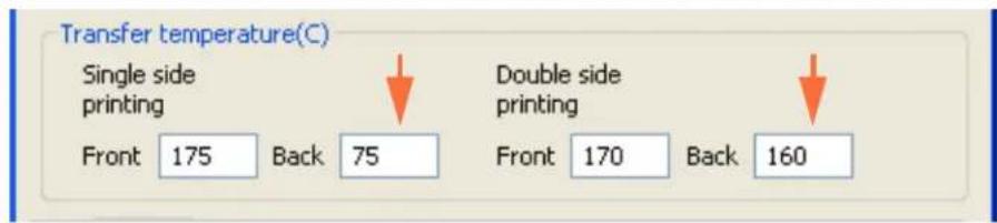
e. Print a test card.
f. Examine the test card.
- If there is noticeable improvement, continue decreasing the back transfer temperature by 5, printing a test card, and examining the resulting card. Stop when the problem is corrected or there is no more improvement. If the problem is corrected, no more adjustment is required; otherwise go to Step 3.
- If there is no noticeable improvement, return the temperature to its default setting; and go to Step 3.
Step 3. Increase Transfer Output Speed
a. From the Card Specifications window, make a note of the default transfer output speed settings.
b. Increase the appropriate (single or double) transfer output speed by 0.2.
c. Click on the OK button.

d. Print a test card.
e. Examine the test card.
- If there is noticeable improvement, continue increasing the transfer output speed by 0.2, printing a test card, and examining the resulting card. Stop when the problem is corrected or there is no more improvement. If the problem is corrected, no more adjustment is required; otherwise go to Step 4.
- If there is no noticeable improvement, return the transfer output speed to its default setting; and go to Step 4.

Setting Custom Card Specifications
Adjustments
Step 4. Increase Transfer Input Speed
a. From the Card Specifications window, mnake a note of the default transfer input speed settings.
b. Increase the appropriate (single or double) transfer input speed by 0.2.
c. Click on the OK button.
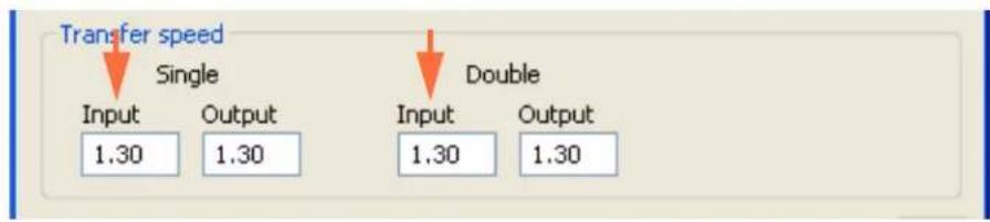
d. Print a test card.
e. Examine the test card.
- If there is noticeable improvement, continue increasing the transfer input speed by 0.2, printing a test card, and examining the resulting card. Stop when the problem is corrected or there is no more improvement. If the problem is corrected, no more adjustment is required. If the problem persists, contact Zebra Technical Support.
- If there is no noticeable improvement, return the transfer input speed to its default setting; and contact Zebra Technical Support.
Flash on Magnetic Stripe
Step 1. Decrease Back Transfer Temperature:
a. Go to the Card Specifications window; see Section B.3.
b. Make a note of the default back transfer temperature settings.
c. Decrease the appropriate (single or double side) back transfer temperature by 5.
d. Click on the OK button.

e. Print a test card.
f. Examine the test card; see Section B.3.
- If there is noticeable improvement, continue decreasing the back transfer temperature by 5, printing a test card, and examining the resulting card. Stop when the problem is corrected or there is no more improvement. If the problem is corrected, no more adjustment is required; otherwise go to Step 2.
- If there is no noticeable improvement, return the temperature to its default setting; and go to Step 2.

Setting Custom Card Specifications
Adjustments
Step 2. Increase Transfer Output Speed
a. From the Card Specifications window, make a note of the default transfer output speed settings.
b. Increase the appropriate (single or double) transfer output speed by 0.2.
c. Click on the OK button.
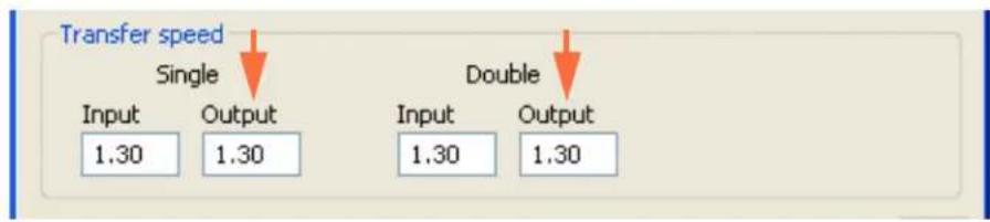
d. Print a test card.
e. Examine the test card.
- If there is noticeable improvement, continue increasing the transfer output speed by 0.2, printing a test card, and examining the resulting card. Stop when the problem is corrected or there is no more improvement. If the problem is corrected, no more adjustment is required; otherwise go to Step 3.
- If there is no noticeable improvement, return the transfer output speed to its default setting; and go to Step 3.
Step 3. Increase Transfer Input Speed
a. From the Card Specifications window, mnake a note of the default transfer input speed settings.
b. Increase the appropriate (single or double) transfer input speed by 0.2.
c. Click on the OK button.

d. Print a test card.
e. Examine the test card.
- If there is noticeable improvement, continue increasing the transfer input speed by 0.2, printing a test card, and examining the resulting card. Stop when the problem is corrected or there is no more improvement. If the problem is corrected, no more adjustment is required. If the problem is corrected, no more adjustment is required; otherwise go to Step 4.
- If there is no noticeable improvement, return the transfer input speed to its default setting; and go to Step 4.

Setting Custom Card Specifications
Adjustments
Step 4. Decrease Front Transfer Temperature:
a. Go to the Card Specifications window.
b. Make a note of the default front transfer temperature settings.
c. Decrease the appropriate (single or double side) front transfer temperature by 5.
d. Click on the OK button.

e. Print a test card.
f. Examine the test card; see Section B.3.
- If there is noticeable improvement, continue decreasing the front transfer temperature by 5, printing a test card, and examining the resulting card. Stop when the problem is corrected or there is no more improvement. If the problem is corrected, no more adjustment is required. If the problem persists, contact Zebra Technical Support.
- If there is no noticeable improvement, return the front transfer temperature to its default setting; and contact Zebra Technical Support.
Excess Leading-Edge Flash on Mag Cards
Use image with black printed line or text above the mag stripe (arrows below).

To assist with this issue, you can use the Inhibit pop-up window, which allows you to select the inhibit panel area for the mag stripe, signature panel, or other non-printing areas of a card; see Inhibit Pop-Up on page 66 for details.

natural_image
Line drawing of a mechanical device with ports and mounting brackets (no text or symbols)Appendix C
Network Operations

natural_image
Abstract black and white pattern with curved white lines on black background (no text or symbols)This section covers:
Setting Up a Network Printer.... 162
Pooling....169
Setting Up a Network Printer
Use this procedure if you have already installed an ethernet printer on your system (refer to Section 2), and you want to install a second ethernet printer on the network via the Microsoft Add Printer Wizard.
Step 1. Click on the Start button, select Control Panel > Printers and Faxes> Add a printer.
Step 2. Observe the Add Printer Wizard window open.

Step 3. Click on the Next button, and observe the Local or Network Printer window.
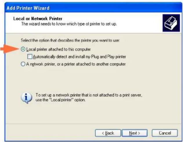
Step 4. Select Local printer attached to this computer. Ensure Automatically detect and install my Plug and Play printer is NOT checked.
Step 5. Click on the Next button
Step 6. Observe the Select a Printer Port window.
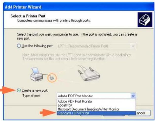
Step 7. Click on the Create a new port radio button.
Step 8. From the dropdown menu, select Standard TCP/IP Port.
Step 9. Click on the Next button, and observe the Add Standard TCP/IP Port Wizard window.

Step 10. Be sure that your printer is turned on and the network is connected and configured.
Step 11. Click on the Next button.
Step 12. Observe a second Add Standard TCP/IP Port Wizard window.

Note • You can get the IP Address via the OCP: INFO button > NETWORK INFO > IP.
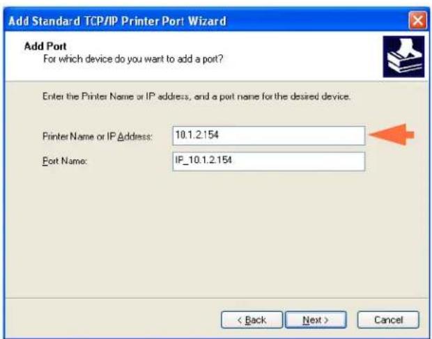
Step 13. Enter the IP Address of your printer. Note that the Port Name will automatically be filled in when you enter the IP Address. Do not change the Port Name.
Step 14. Click on the Next button, and observe the Additional Port Information Required window.

Step 15. Click on the Standard radio button; and from the dropdown menu, select Generic Network Card.
Step 16. Click on the Next button.
Step 17. Observe the Completing the Add Standard TCP/IP Printer Port Wizard window.

Step 18. Click on the Finish button, and observe the Install Printer Software window.
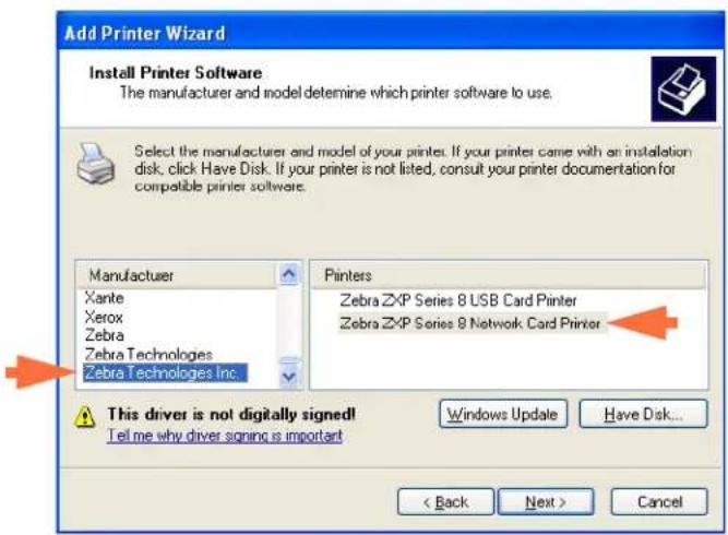
Step 19. Select the Manufacturer (Zebra Technologies Inc) and the Printers (Zebra ZXP Series 8 Network Card Printer).
Step 20. Click on the Next button.
Step 21. Observe the Use Existing Driver window.
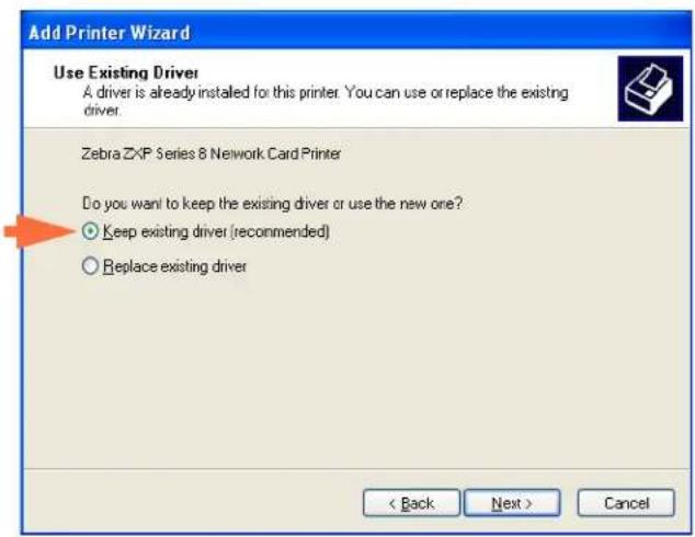
Step 22. Select the Keep existing driver radio button.
Step 23. Click the Next button, and observe the Name Your Printer window.

Step 24. Enter the printer name, use the default name, or add more information to indicate the printer location; e.g., Mike's Office, Hallway, Room 33, etc.
Step 25. Select the appropriate radio button in answer to the question Do you want to use this printer as the default printer?
Step 26. Click the Next button.
Step 27. Observe the Printer Sharing window.

Step 28. Select the appropriate radio button in answer to the question Do you want to share this printer...? Enter the Share name if applicable.
Step 29. Click the Next button, and observe the Print Test Page window.

Step 30. Select the appropriate radio button in answer to the question Do you want to print a test page?
Step 31. Click the Next button.
Step 32. Observe the Completing the Add Printer Wizard window.

Step 33. Click on the Finish button to complete the Add Printer Wizard.
You have successfully installed the network printer.
Pooling
Setting Up the Printer Pool
Printer Pooling is a standard feature of Windows, which lets you spread your printed output across a pool of several printers. In this example, we will install and setup the three network printers to be used for pooling.
Step 1. Before proceeding to pool the printers, test them individually, and be sure they are configured similarly. Specifically, check the following:
- Ribbon panel configuration (ribbon type, and what prints on which side of the card).
- Mag encoding configuration.
- Black extraction configuration (if applicable).
Step 2. Access the Ports Tab.
To access the Ports tab, select Start > Printers and Faxes. Right click on the Zebra ZXP Series 8 Card Printer listing. Select Properties > Ports.

Step 3. Select the Enable printer pooling checkbox (arrow above).
Step 4. Select the three printers by clicking on the associated checkbox (circle above).
Using the Printer Pool

Note • Send print jobs to the pool, not to an individual printer.
When the first printer has taken as many jobs as it can handle (that being two jobs - one to be printed immediately, the other waiting), the following jobs “spill over” to the second printer, and then to the third printer.
Note that if you are only printing two jobs, they would both go to the first printer. Pooling is a spill-over methodology. It does not balance printer usage.
Once the pool has been set up, maintenance and configuration changes should be done through the menus for each individual printer, not through the pool (which can produce undesirable results).

Important • The effect of any maintenance and/or changes can (and should) be tested by sending print jobs separately to each printer, not to the pool.
Appendix D
Magnetic Card Encoder

natural_image
Abstract black and white pattern with curved white lines on black background (no text or symbols)Introduction
This Appendix includes operation and maintenance requirements for Printers with the optional magnetic card stripe encoder.

he magnetic encoder can be set for either high or low coercivity, which must match the cards being used. Use the printer driver to change the encoder setting.
Driver Setting
The Card Setup tab allows the user to specify the Magnetic Encoder Card Type in use. Based on your selection, the printer automatically adjusts various printer properties for optimum performance.
If your card type is not listed in the drop-down menu, select Custom and fill out the Card Specifications pop-up screen.
To access the Card Setup Tab, select Start > Printers and Faxes. Right click on the Zebra ZXP Series 8 Card Printer listing; and select Printing Preferences > Card Setup.
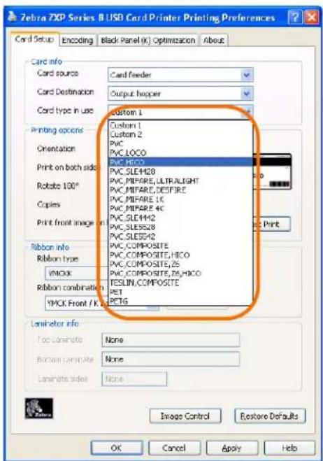
- Make the appropriate Magnetic Encoder Card Type selection.
Media Loading Orientation

Note • ONLY USE cards that comply with ISO 7810 and 7811 standards for magnetic stripe cards. The magnetic stripe must be flush to the surface of the card to work properly. Never use cards which have taped-on magnetic stripes.
Place the cards in the Input Hopper in the correct orientation as shown (with the magnetic stripe down and facing to the rear). Ensure that the cards are seated properly the hopper.

natural_image
Technical line drawing of a mechanical device with orange arrows indicating flow or movement, no text or symbols presentMagnetic Encoder Cleaning
The Magnetic Encoder is cleaned as part of the printer cleaning process; see Section 6. If the frequency of encoding errors increases, the head may need additional cleaning. To cleans, only use foam-tipped swabs.

Caution • Never use a sharp object or any abrasive to scrape deposits from the Magnetic Encoder. Permanent damage to the Magnetic Head will result.
Step 1. Open the Door.
Step 2. Open the idler roller assembly door.
Step 3. Bend the Cleaning Swab to release the cleaning fluid.
Step 4. Clean the Magnetic Encoder by moving Cleaning Swab tip side-to-side across the head elements. To re-order Cleaning Swabs, see the Media List on the User Documentation and Drivers CD supplied with this printer.
Step 5. Close the idler roller assembly door.
Step 6. Close the Door.
Magnetic Encoding Type
ISO (Default)
The encoder reads and writes standard ISO track data formats in standard ISO track locations. The following shows the three standard ISO tracks.

Each track can be encoded and decoded with ASCII characters in the standard default ISO data formats:
| Track Density(bits per inch) | Bits per character | Character parity | Length (characters) | LRC parity | Start sentinel | End sentinel | Start sentinel offset inches (mm) | |
| 1 210 7 Odd 76 Even % ? 0.293" (7.4) | ||||||||
| 2 | 75 | 5 | Odd | 37 | Even | ; | ? | 0.293" (7.4) |
| 3 | 210 | 5 | Odd | 104 | Even | ; | ? | 0.293" (7.4) |
The magnetic encoder can read or encode up to 3 tracks of digital information onto CR-80 cards incorporating a HiCo or LoCo magnetic stripe in the ISO 7811 format.
Encoding for the three tracks uses the ISO 7811 format.
- Track 1 uses 210 BPI (bits per inch) encoding in the International Air Transport Association (IATA) format of 79 alphanumeric characters, at 7 bits per character.
- Track 2 uses 75 BPI encoding to store 40 numeric characters at 5 bits per character in American Banking Association (ABA) format.
- Track 3 uses 210 BPI encoding of 107 numeric characters at 5 bits per character in THRIFT format.
The ISO data formats include a preamble (all zeros), a start character, data (7-bit or 5-bit as specified by ISO), a stop character, and a longitudinal redundancy check (LRC) character. The 7-bit data format has 6 bits of encoded data and a parity bit. The 5-bit data format has 4 bits of encoded data and a parity bit.
The ISO data formats include a data field separator (or delimiter) that allows parsing of the encoded track data. An example of separate data fields would be the ABA data format (Track 2) that includes a Primary Account Number (PAN) field and an account information field (for expiration date, country code, etc.).
AAMVA
Alpha-numeric characters on Tracks 1 and 3, numerals only on Track 2.
| Track Density(bits per inch) | Bits per character | Character parity | Length (characters) | LRC parity | Start sentinel | End sentinel | Start sentinel offset inches (mm) |
| 1 210 7 Odd 79 Even % ? 0.293" (7.4) | |||||||
| 2 | 75 | 5 | Odd | 37 | Even | ; | ? 0.293" (7.4) |
| 3 210 7 Odd 79 Even % ? 0.293" (7.4) | |||||||
CUSTOM
If a custom format is desired, the ISO standard format may be used as a starting point. The standard format can then be modified by assigning different values to any or all of the density, character, and sentinel attributes. (If any of these attributes is missing, its corresponding value in the standard ISO format will be substituted.)
BINARY
The binary option allows the user to specify directly the value for each bit on the mag stripe:.
In this “direct binary” mode, it is the host’s responsibility to fully populate the magnetic stripe; i.e., the hex data provided by the host must include the leading zeroes, start sentinel, data, end sentinel, LRC, and trailing zeroes. Note that the magnetic stripe is encoded from the right-hand end as viewed from the “stripe” side, with the stripe uppermost. The least significant bit of the data is encoded first.
A sufficient number of leading zeroes should be prepended to offset the start sentinel by approximately 0.3" (7.5 mm) from the right-hand end, as in the ISO format. Care should be taken to ensure that the payload data does not exceed the capacity of the tracks at their specified recording densities. (In the binary mode, out-of-range data is not recorded, and no error condition will result.)
A CR-80 size card has a nominal capacity of 252 bits per track at 75 BPI, and 708 bits at 210 BPI. These capacities equate approximately to 31 hex bytes (248 binary bits) and 88 hex bytes respectively.
Encoder Macro Commands
With ZXP Series 8 printers, we provide support for pass-through mag encoding commands.
The application developer or user can use a preamble or Macro to indicate to the driver that the data following the Preamble or Macro is to be mag encoded.
The user can have encoding and printing data on the same card, and the driver will filter out the encoding data from the printing data. The user does not have to know job control syntax or ZMotif commands to send mag encoding commands to the printer.
Supported Macro commands are:
1. C01<Track1 Data>
C02<Track2 Data>
C03<Track3 Data>
- 1
2 3
3. ~1=<Track1 data>
~2=<Track2 data>
~3=<Track3 data>
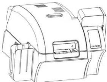
natural_image
Technical line drawing of a mechanical device with no visible text or symbolsAPPENDIX E
Smart Card Options

natural_image
Abstract black and white pattern with curved white lines on a black background (no text or symbols)Introduction
This Appendix contains information on the additional operations of a Printer equipped with one or more of the available Smart Card options.
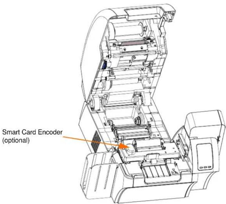
Smart Cards can have a built-in microcomputer and/or memory to store fingerprints, voice recognition patterns, medical records, and other such data. All other printer operations remain the same as the standard models.
Encoding and Reading Smart Cards
Encoding data onto Smart Cards and reading the data previously encoded on them is totally under control of the application software; no operator action is required.
If you experience any problems with encoding or reading data, refer to the users manual or other documentation for the application software.
Driver Setting
The Card Setup tab allows the user to specify the Smart Card Type in use. Based on your selection, the printer automatically adjusts various printer properties for optimum printer performance.
If your card type is not listed in the drop-down menu, select Custom and fill out the Card Specifications pop-up screen.
To access the Card Setup Tab, select Start > Printers and Faxes. Right click on the Zebra ZXP Series 8 Card Printer listing; and select Printing Preferences > Card Setup.

- Make the appropriate Smart Card Type selection.
Contact Smart Cards
Contact Smart Cards have a pad of contacts on the surface of the card that connect to the circuitry embedded into the card.
The printer responds to commands that position the card at the contact location, where the printer connects to the contacts on the Smart Card. Data to be encoded onto the Smart Card, and data read from the Smart Card, can interface via a connector on the printer's rear panel (Contact Station), or encoding/decoding can be performed by logic on the printer's Main PCBA (Contact Encoder).
All other printer operations remain the same as the standard models.
Media Loading Orientation for Contact Smart Cards
Place the cards in the Input Hopper in the correct orientation as shown (with the gold-plated Smart Card contacts at the top surface of the card and facing to the left). Ensure that the cards are seated properly the hopper.

natural_image
Technical line drawing of a mechanical device with an orange arrow indicating a component or operation, next to stacked books (no text or symbols present)Contact Station Smart Card Interface
When a command to the printer interface sends a card to the Smart Card Contact Station, the printer connects the Smart Card Contact Station to the female DB-9 connector on the rear of the printer.

natural_image
Line drawing of a computer front panel with ventilation grilles and control buttons (no text or symbols)DB-9 Connector location for Smart Card Contact Station
An attached external Smart Card Programmer can be used to program Smart Card chips. The following table shows the Smart Card Contact Points.
| Pin | Smart Card Contact Points | DB-9 | Smart Card Contact Points |
| 1 C1 (VCC) 6 C6 (Vpp) | |||
| 2 C2 (Reset) 7 C7 (I/O) | |||
| 3 C3 (Clock) 8 C8 (RFU) | |||
| 4 | C 4 | 9 | ( GND when chip is at station) |
| 5 C5 (GND) |
Contactless Smart Cards
Rather than using a contact pad, Contactless Smart Cards use various short-range radio technologies to “connect” to the printer. The printer moves the card to an antenna location on the card path, and the encoding or decoding occurs. All other printer operations remain the same.
Media Loading Orientation for Contactless Smart Cards
For Contactless Smart Cards, orientation is not a consideration.
Printing on Contactless Smart Cards
With reverse transfer printing technology, there are no restrictions when designing material to be printed on Contactless Smart Cards.
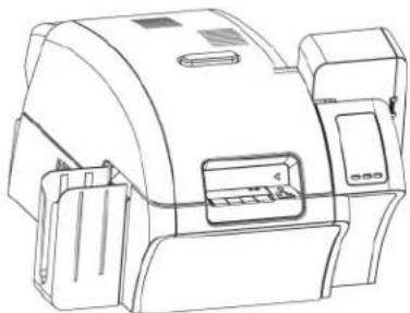
natural_image
Line drawing of a mechanical device with no visible text or symbolsAppendix F
Packing the Printer for Shipment

natural_image
Abstract black and white pattern with curved white lines on a black background (no text or symbols)Introduction
If the printer is to be shipped, it is important to use the original packing and shipping material to prevent damage to the Printer.
If the original material is lost, a replacement Shipping Kit can be ordered from Zebra; see the Spare Part Kits listing in the Service Manual or check the Partner Zone on www.zebracard.com.
Procedure

Note • The specifics of the shipment and the printer's condition may influence which of the following steps are followed; common sense should prevail.
Step 1. Remove any cards from the Input and Output Hoppers.
Step 2. If the printer still has power applied and is turned on and is still connected to the host computer, set the printer's power switch (on the back of the printer) to the OFF (Q position; and disconnect the interface and power cables to the printer.
Step 3. Open the printer Door.
Step 4. Remove the Print Ribbon and Transfer Film. (If you wish to save the print ribbon and film for future use, you may want to put them in a plastic bag for storage.)
Step 5. Remove the Card Cleaning Cartridge and Card Cleaning Roller, and place them in the foam insert.
Step 6. Close the printer Door.
Step 7. Remove the Input and Output Hopper, and place them in the foam insert.

Note • In the figure below, the printer and accessories are shown in the bottom foam insert, out of the shipping carton for clarity.

Step 8. Place the Printer in its protective plastic bag.
Step 9. Place the lower foam insert in the Shipping Carton.
Step 10. Use both hands to carefully place the Printer into the recess in the lower foam insert.
Step 11. Place the upper foam insert onto the Printer, and gently press it down so it makes a snug fit on the Printer -- the top of the upper foam insert should be even with the upper edge of the Shipping Carton.
Step 12. Close the Shipping Carton.
Step 13. Tape the Shipping Carton securely.
For Technical Support or Repair Services, contact the appropriate facility listed below.
North America and Latin America - Technical Support
Phone: +1 877 ASK ZEBRA (877 275 9327)
+1 847 913 2259
email: ts1@zebra.com
North America and Latin America - Repair Services
Before returning any equipment to Zebra Technologies Corporation for in-warranty or out-of-warranty repair, contact Repair Services for a Repair Order (RO) number. Mark the RO number clearly on the outside of the box. Ship the equipment, freight prepaid, to the address listed below:
Zebra Technologies Repair Services
333 Corporate Woods Parkway
Vernon Hills, IL 60061
webform: www.zebra.com/repair
Phone: 1-877-275-9327
email: repair@zebra.com
Europe, Middle East, and Africa - Technical Support
| Language Phone Email | ||
| German +49 (0) 2159 676 870 zebratechDE@zebra.com | ||
| French +33 (0) 1 53 48 12 74 zebratechFR@zebra.com | ||
| English +44 (0) 1628 556 225 zebratechUK@zebra.com |
For further assistance, contact:
Zebra Technologies Card Printer Solutions
Dukes Meadow
Millboard Road, Bourne End
Buckinghamshire SL8 5XF, UK
Phone: +44 (0) 1628 556 025
FAX: +44 (0) 1628 556 001
e-mail: cardts@zebra.com
Europe, Middle East, and Africa - Repair Services
Before returning any equipment to Zebra Technologies Corporation for in-warranty or out-of-warranty repair, contact your supplier for a Return Materials Authorization (RMA) number, or contact one of the following repair centers for support and instructions:
| Type of repair and location Phone | ||
| Depot Repair in Germany, Austria, Switzerland | +49 (0) 2159 676 870 zebracareDE@zebra.com | |
| Depot Repair in France | +33 (0) 1 53 48 12 74 | zebracareFR@zebra.com |
| Depot and On-Site Repair in UK and Ireland | +44 (0) 1628 556 225 zebracareUK@zebra.com | |
| Depot Repair in South Africa | +27 (0) 11 201 7777 | - |
| Depot Repair in the Middle East +971 | (0) 46058220 support_dxb@emitac.ae |
For further assistance, contact:
For assistance anywhere in the EMEA, contact After Sales Customer Services at:
Phone: +44 (0) 177 2 69 3069
email: ukrma@zebra.com
Asia Pacific - Technical Support
Zebra Technologies Asia Pacific Pte. Ltd.
120 Robinson Road
06-01 Parakou Building
Singapore 068913
Phone: +65 6858 0722
Fax: +65 6885 0838
Email: tsasiapacific@zebra.com
Asia Pacific - Repair Services
Before returning any equipment to Zebra Technologies Corporation for in-warranty or out-of warranty repair, contact Repair Services for a Return Materials Authorization (RMA) number. Repack the equipment in the original packing material, and mark the RMA number clearly on the outside. Ship the equipment, freight prepaid, to either address listed below:
Zebra Technologies Asia Pacific Pte. Ltd.
No.5 Changi North Way Level 3
Singapore 498771
Agility Building
Phone: +65 6546 2670 ext 3203 and 3204
Fax: +65 6546 5328
Email: APACRepair@zebra.com
Zebra Website
www.zebracard.com

natural_image
Line drawing of a mechanical device with no visible text or symbols

- Zebra® ZXP Series 8™ Card Printer
- Copyright Notice
- Trademarks
- Product Disposal
- Contents
- • Introduction. 1
- · Installation and Setup. 7
- 3·Operation. 35
- • Printer Settings and Adjustments .... 51
- • ZXP Series Toolbox.... 71
- • Cleaning. 93
- • Troubleshooting ..... 99
- • Technical Specifications .....111
- Appendix A • Printer Configurations .....117
- Appendix B • Setting Custom Card Specifications. .....119
- Appendix C • Network Operations ..... 161
- Appendix D • Magnetic Card Encoder ..... 171
- Appendix E • Smart Card Options 179
- Appendix F • Packing the Printer for Shipment. 185
- Appendix G • Worldwide Support. 187
- Components
- Front View, Printer Cover Open
- Introduction
- Controls, Connectors, and Indicators
- Icons
- Zebra Supplies
- 2
- Installation and Setup
- General Information
- Unpacking the Printer
- Installing the Card Hoppers
- Input Hopper
- Output Hopper
- Loading Cards
- Opening the Printer Door
- Installing the Card Cleaning Cartridge
- Installing the Card Cleaning Roller
- Loading the Transfer Film
- Loading a Print Ribbon
- Connecting Power
- Connecting the Printer to your Computer
- USB Connection
- Installing the Windows Printer Driver Initial Steps
- Requires Internet Connection
- Installing the USB Printer Driver
- Installing the Ethernet Printer Driver
- Step 14. Identify the printer:
- Card Type Selection
- Printing a Sample Card
- Manual Card Feed
- Operator Control Panel (OCP)
- Messages
- Warning Messages
- Error Messages
- Printer Menu Information
- Info Menu
- Operation
- Print Test Cards Menu
- Advanced Settings Menu
- Clean Printer Menu
- Ethernet Indicators -- Detail
- Link/Activity Indicator (Green)
- Speed Indicator (Orange)
- Printer Settings and Adjustments
- Properties
- General Tab
- Sharing Tab
- Ports Tab
- Advanced Tab
- Color Management Tab
- Security Tab
- Device Information Tab
- Printing Preferences
- Card Setup Tab
- Advanced Black Panel Options Pop-Up
- Uv Panel Pop-Up
- - Select the Uv type:
- Inhibit Pop-Up
- - Select the inhibit panel area:
- Image Control Option
- Encoding Tab
- Black Panel (K) Tab
- About Tab
- ZXP Series Toolbox
- ZXP Series Toolbox Access
- Information
- Printer
- Sensors
- Media
- Configuration
- Image Control
- Job Log
- Save/Restore
- Firmware and Settings
- • Temperature and Position Settings
- Cleaning
- Clean Printer
- - Side Card Path
- - Front Card Path
- - Heater Rollers
- Print Test Card
- Print Sample Card
- Technology
- Magnetic Encoding
- Smart Card
- Advanced Security
- Configure Security
- Textbox Password:
- vanced Password:
- Last Print job option:
- Establish Security Roles
- Print Viewer
- Print PRN file
- Cleaning the Printer
- When to Clean
- Cleaning the Rollers
- Cleaning the Platen
- Cleaning the Printhead
- Card Cleaning Cartridge
- Card Cleaning Roller
- Troubleshooting
- OCP Test Card Images
- Ethernet Issues
- Technical Specifications
- Standard Features
- Specifications
- Encoding Options
- Communications Interfaces
- Software
- Microsoft Windows Certified Printer Drivers Supported
- Driver Features
- ZXP Toolbox
- Card Compatibility
- Agency Approvals
- Electrical
- Physical
- Environmental
- Declarations of Conformity
- ZEBRA TECHNOLOGIES CORPORATION
- Zebra ZXP Series 8 Card Printer
- CE
- Applicable Directives and Supporting Standards:
- RFID Enabled
- FCC Radiation Exposure Statement (applicable to 15.247 device only)
- Industry Canada Notice
- Japan: Ministry of Internal Affairs and Communications (MIC) Certification
- APPENDIX A
- Printer Configurations
- Appendix B
- Setting Custom Card Specifications
- B.1 Introduction
- B.2 Process Flowchart
- B.3 3-Step Process
- Step 1: Select the Card Type
- Step 2: Make adjustments
- Step 3: Print and examine Test Card
- Adjustments
- B.4 Adjustments
- B.4.1 Adjustment Overview
- B.4.2 Partial Transfer
- Front of card
- Step 2. Decrease Transfer Input Speed
- Step 3. Decrease Transfer Output Speed
- Back of card
- B.4.3 Warpage
- Edges curled down
- Step 1. Decrease Back Transfer Temperature:
- Step 2. Increase Front Transfer Temperature:
- Step 3. Increase Transfer Output Speed
- Edges curled up
- Step 1. Decrease Front Transfer Temperature:
- Step 2. Increase Back Transfer Temperature:
- Irregular Warpage
- Step 2. Decrease Back Transfer Temperature:
- Step 4. Increase Transfer Input Speed
- B.4.4 Card Indentation
- B.4.5 Flash
- Side Edge
- Leading Edge
- B.4.6 Special Cases
- Flash on Smart Card Chip
- Flash on Magnetic Stripe
- Step 2. Increase Transfer Output Speed
- Step 3. Increase Transfer Input Speed
- Step 4. Decrease Front Transfer Temperature:
- Excess Leading-Edge Flash on Mag Cards
- Appendix C
- Network Operations
- Setting Up a Network Printer
- Pooling
- Setting Up the Printer Pool
- Using the Printer Pool
- Appendix D
- Magnetic Card Encoder
- Driver Setting
- Media Loading Orientation
- Magnetic Encoder Cleaning
- Magnetic Encoding Type
- ISO (Default)
- AAMVA
- CUSTOM
- BINARY
- Encoder Macro Commands
- APPENDIX E
- Smart Card Options
- Encoding and Reading Smart Cards
- Contact Smart Cards
- Media Loading Orientation for Contact Smart Cards
- Contact Station Smart Card Interface
- Contactless Smart Cards
- Media Loading Orientation for Contactless Smart Cards
- Printing on Contactless Smart Cards
- Appendix F
- Packing the Printer for Shipment
- Procedure
- North America and Latin America - Technical Support
- North America and Latin America - Repair Services
- Europe, Middle East, and Africa - Technical Support
- For further assistance, contact:
- Europe, Middle East, and Africa - Repair Services
- Asia Pacific - Technical Support
- 06-01 Parakou Building
- Asia Pacific - Repair Services
- Zebra Website
Brand : ZEBRA
Model : Z82
Category : Card printer