
K7302 - Charger VELLEMAN - Free user manual and instructions
Find the device manual for free K7302 VELLEMAN in PDF.


| Product Type | Battery Charger |
| Brand | Velleman |
| Model | K7302 |
| Input Voltage | 100-240 V AC, 50/60 Hz |
| Output Voltage | Typically 1.2-12 V DC (depending on battery type) |
| Charging Current | Up to 1 A |
| Compatible Battery Types | NiCd, NiMH, Li-ion, Lead-acid |
| Number of Channels | 1 |
| Protection Features | Overcharge, short circuit, reverse polarity protection |
| Dimensions | Approx. 120 x 70 x 40 mm |
| Weight | Approx. 200 g |
| Power Supply | Mains powered with detachable cord |
| Display | LED indicators for charging status |
| Operating Temperature | 0°C to 40°C |
| Storage Temperature | -20°C to 60°C |
| Certifications | CE, RoHS |
| Maintenance | Clean with a dry cloth; avoid moisture |
| Safety Instructions | Read manual before use; do not charge non-rechargeable batteries |
| Spare Parts Availability | Contact Velleman support for replacement parts |
| Repairability | Repairs should be carried out by qualified personnel only |
| Country of Origin | China |
| Warranty | 2 years (excluding wear and tear) |
Frequently Asked Questions - K7302 VELLEMAN
User questions about K7302 VELLEMAN
0 question about this device. Answer the ones you know or ask your own.
Ask a new question about this device
Download the instructions for your Charger in PDF format for free! Find your manual K7302 - VELLEMAN and take your electronic device back in hand. On this page are published all the documents necessary for the use of your device. K7302 by VELLEMAN.
USER MANUAL K7302 VELLEMAN
Total solder points: 20
Difficulty level: beginner 1 ☑ 2 ☐ 3 ☐ 4 ☐ 5 ☐ advanced
velleman®-kit HIGH-Q
UNIVERSAL BATTERY CHARGER
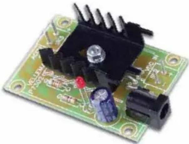
natural_image
Close-up of a green printed circuit board with electronic components and connectors (no visible text or symbols)K7302
Low cost solution for charging of both NiCd and NiMn batteries.
ILLUSTRATED ASSEMBLY MANUAL H7302IP-1
Specifications:
☑ Charges Ni Cd or Ni MH batteries.
☑ Ideal for in car use.
☑ Transforms a mains adapter into a charger (adapter socket included).
☑ Charge cellular phone, toys, portables, video batteries ...
☑ Selectable charge current.
☑ LED charge indication.
Features:
- Charge current (±20%): 50mA, 100mA, 200mA, 300mA, 400mA. (selectable)
• Supply voltage: from 6.5VDC to 21VDC (depending on used battery)
• Supply current: same as charge current.
• Power supply polarity protected.
• LED function indication.
• Dimensions: 40 x 60 mm
• Fits in G403 type housing
1. Assembly (Skipping this can lead to troubles!)
Ok, so we have your attention. These hints will help you to make this project successful. Read them carefully.
1.1 Make sure you have the right tools:
- A good quality soldering iron (25-40W) with a small tip.
- Wipe it often on a wet sponge or cloth, to keep it clean; then apply solder to the tip, to give it a wet look. This is called 'thinning' and will protect the tip, and enables you to make good connections. When solder rolls off the tip, it needs cleaning.
- Thin raisin-core solder. Do not use any flux or grease.
- A diagonal cutter to trim excess wires. To avoid injury when cutting excess leads, hold the lead so they cannot fly towards the eyes.
- Needle nose pliers, for bending leads, or to hold components in place.
- Small blade and Phillips screwdrivers. A basic range is fine.

For some projects, a basic multi-meter is required, or might be handy
1.2 Assembly Hints :
⇒ Make sure the skill level matches your experience, to avoid disappointments.
⇒ Follow the instructions carefully. Read and understand the entire step before you perform each operation.
⇒ Perform the assembly in the correct order as stated in this manual
⇒ Position all parts on the PCB (Printed Circuit Board) as shown on the drawings.
Values on the circuit diagram are subject to changes.
⇒ Values in this assembly guide are correct*
⇒ Use the check-boxes to mark your progress.
⇒ Please read the included information on safety and customer service
* Typographical inaccuracies excluded. Always look for possible last minute manual updates, indicated as 'NOTE' on a separate leaflet.

natural_image
Line drawing of a soldering iron with a curved wire (no text or symbols)
natural_image
Line drawing of two pair of pliers (no text or symbols)

1.3 Soldering Hints :
1- Mount the component against the PCB surface and carefully solder the leads
2- Make sure the solder joints are cone-shaped and shiny
3- Trim excess leads as close as possible to the solder joint


natural_image
Illustration of a hand using a pen to draw a U-shaped object on a flat surface (no text or symbols)

REMOVE THEM FROM THE TAPE ONE AT A TIME!
AXIAL COMPONENTS ARE TAPED IN THE CORRECT MOUNTING SEQUENCE!

natural_image
Abstract curved line diagram with horizontal lines and dots, no text or symbols present
You will find the colour code for the resistances and the LEDs in the HALG (general manual) and on our website: http://www.velleman.be/common/service.aspx
Charging batteries
Determining the charge current:
Before building the kit, one must determinate how much current will be used to charge the battery or battery pack.
It is advisable to charge the battery with a current that is 10 times smaller then the battery capacity, and to charge it for about 15 hours. If you double the charge current, then you can charge the battery in half the time.
Example:
A battery pack of 6V / 1000mAh can be charged with 100mA during 15 hours. If you want to charge faster, then a charge current of 200mA can be used for about 7 hours.
CAUTION: The higher the charge current, the more critical the charge time must be checked. When faster charging is used, it is advisable to discharge the battery completely before charging.
Using a charge current of 1/10 of the capacity will expand the lifetime of the battery. The charge time can easily be doubled without damaging the battery.
Determining the supply voltage :
This table indicates the minimum and maximum voltages to supply the charger.
Example:
To charge a 6V battery a minimum supply voltage of 12V is needed, the maximum voltage is then 15V.
| Supply voltage | Usable adapter | ||
| Battery Voltage Min. | Max. type | ||
| 1.2V | 6.5V | 10V | |
| 2.4V | 7.5V | 11V | |
| 3.6V | 9.6V | 12V | |
| 4.8V | 10.5V | 13V | |
| 6V | 12V | 15V | |
| 7.2V | 13.2V | 16V | |
| 8.4V | 14.5V | 17V | |
| 9.6V | 15.6V | 18V | |
| 10.8V | 16.8V | 19V | |
| 12V | 18V | 21V | |
1. Diode. Watch the polarity!

D1 : 1N4007

2. 1/2W Resistor


R1 : 120 (1 - 2 - 1 - B - 9).
3. Resistor

The value of resistor R2 determines the charge current:

R2
| 50mA : | 47 1/4W | (4 - 7 - 0 - B) |
| 100mA : | 18 1/4W | (1 - 8 - 0 - B) |
| 200mA : | 6,8 1/4W | (6 - 8 - B - B) |
| 300mA : | 3,9 1/2W | (3 - 9 - B - B - 9) |
| 400mA : | 2,7 1/2W | (2 - 7 - B - B - 9) |
4. LED (check the polarity!)
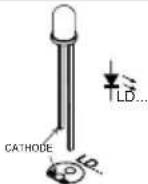


LD1:3mm low current RED

REMARK: Depending on the used housing, the LED can be mounted at a higher position, to make it visible through a hole in the housing.
5. PCB pins
To connect the input and output wires via PCB tabs, mount pins at positions SK2 and SK3


SK2: +

SK3: +

SK2: -

SK3 : -
6. Electrolytic Capacitor. Watch the polarity!

C1 : 220μF

natural_image
Technical illustration of two cylindrical electronic components with mounting holes, one with a capacitor symbol (no text or labels)7. DC Jack


Remark: even if the DC adapte jack is not used, it must be mounted, due to the internal switch.

SK1:DJ-005
8. Transistor


T1 : BD135
Mount the transistor together with the heatsink on the PCB, bend the leads as necessary. Take care that the metal back of the transistor touches the heatsink. Check that the leads of the transistor do not touch the heatsink.
9. Mounting in an housing
The PCB can easily be mounted into our housing type G403.
Due to heat dissipation, it is advisable to make some 4mm ventilation holes into the housing. Holes for the adapter jack and wires will also be necessary.
10. Connection

flowchart
graph LR
    A["DC ADAPTOR"] --> B["P7302"]
    B --> C["RECHARGEABLE BATTERY"]
    B --> D["VDC IN +"]
    B --> E["ACCU OUT +"]
    B --> F["Ground"]

flowchart
graph LR
    A["DC POWER SUPPLY"] --> B["P7302"]
    B --> C["RECHARGEABLE BATTERY"]
    B --> D["VDC"]
    B --> E["IN"]
    B --> F["ACCU"]
    B --> G["OUT"]

☐ Connecting the supply voltage and the battery. See table on page 6 for suitable supply voltage
- Schematic diagram

12. PCB

VELLEMAN Components NV
Legen Heirweg 33
9890 Gavere
Belgium Europe
www.velleman.be
www.velleman-kit.com
Modifications and typographical errors reserved
© Velleman Components nv.
H7302IP - 2004 - ED1

- UNIVERSAL BATTERY CHARGER
- K7302
- Specifications:
- Features:
- Assembly (Skipping this can lead to troubles!)
- Make sure you have the right tools:
- For some projects, a basic multi-meter is required, or might be handy
- Assembly Hints :
- Soldering Hints :
- REMOVE THEM FROM THE TAPE ONE AT A TIME!
- Charging batteries
- Determining the charge current:
- Example:
- Determining the supply voltage :
- Diode. Watch the polarity!
- 1/2W Resistor
- Resistor
- LED (check the polarity!)
- PCB pins
- Electrolytic Capacitor. Watch the polarity!
- DC Jack
- Transistor
- Mounting in an housing
- Connection
- PCB
Brand : VELLEMAN
Model : K7302
Category : Charger