
Ambition Robo Scooter 300 - Lawn mower Wolf Garten - Free user manual and instructions
Find the device manual for free Ambition Robo Scooter 300 Wolf Garten in PDF.


| Product Type | Robotic Lawn Mower |
| Brand | Wolf Garten |
| Model | Ambition Robo Scooter 300 |
| Dimensions (L x W x H) | Approx. 55 x 40 x 30 cm |
| Weight | Approx. 10 kg |
| Power Source | Rechargeable lithium-ion battery |
| Battery Voltage | 18 V |
| Cutting Width | 22 cm |
| Cutting Height Range | 20 – 60 mm |
| Max. Slope Capability | Up to 25% (14°) |
| Mowing Area Capacity | Up to 300 m² |
| Rain Sensor | Yes, automatic return to charging station |
| Control | Via control panel on device; optional app connectivity |
| Charging Station Included | Yes |
| Boundary Wire | Yes, included for defining mowing area |
| Noise Level | Approx. 60 dB(A) |
| Protection Class | IPX4 (splash water resistant) |
| Maintenance | Regular cleaning of blades, undercarriage, and sensors; replace blades when dull |
| Safety Features | Lift sensor, tilt sensor, rain sensor, automatic shut-off when lifted |
| Spare Parts Availability | Blades, wheels, batteries, charging station parts available via Wolf Garten service |
Frequently Asked Questions - Ambition Robo Scooter 300 Wolf Garten
User questions about Ambition Robo Scooter 300 Wolf Garten
0 question about this device. Answer the ones you know or ask your own.
Ask a new question about this device
Download the instructions for your Lawn mower in PDF format for free! Find your manual Ambition Robo Scooter 300 - Wolf Garten and take your electronic device back in hand. On this page are published all the documents necessary for the use of your device. Ambition Robo Scooter 300 by Wolf Garten.
USER MANUAL Ambition Robo Scooter 300 Wolf Garten
1
2
3
4
5
6
7
Base Station and Power Box:
- Generates signal along the wire.
- Charges Robomow's battery.
Large trees: Robomow is allowed to bump
into them. at this size, the objects do not
require a Perimeter Wire around them

Tree surrounded by a groove, ditch or flower beds requires a wire around it.
2.2 Funktionsweise



13


Oder:


How to calculate the slope of your lawn?
35 cm(Elevation)/100 cm(Length) = 35 % (slope)

WICHTIGE INFORMATION


6. Betrieb
L2 - Separate Zone A
L3 - Separate Zone B


WICHTIG
- Introduction And Safety 47
- Know Your Unit 50
- Planning Ahead 53
- Initial Setup 58
- Preparing the Unit 68
- Operation 71
- Using The Power Box 76
- Charging 77
- Troubleshooting and User Messages 78
- Product Specification 83
- Maintenance and Storage 84
- Accessories 86
- Tips for maintaining your lawn 87
Warranty 88
1. Introduction And Safety
1.1 Introduction
Product, product specifications and this document are subject to change without notice. All other trademarks are property of their respective owners.
Welcome to the world of home robotics!
Thank you for purchasing our product. We know that you will enjoy the extra free time you will have while using the unit to mow your lawn. When set up and used properly, the unit will operate safely on your lawn and provide you with a quality of cut matched by a few mowers of any kind. You will be impressed with your lawn's appearance and best of all, the unit did it for you.
IMPORTANT!
The following pages contain important safety and operating instructions. Please read and follow all instructions in this manual. Carefully read and review all safety instructions, warnings and cautions contained in this manual. Failure to read and follow these instructions, warnings and cautionary statements may result in severe injury or death to persons and pets or damage to personal property.
1.2 Warning Decal Definitions
These are the symbols on the unit; Read them carefully before operating the unit.

1
2
3
4
5 7
- This is a dangerous power tool. Use care when operating and follow all safety instructions and warnings.
- Read through the Operating & Safety Manual carefully before operating your unit.
- Hazard of throwing or flying objects while in operation.
- Keep a safe distance from the unit when operating. Keep people in particular children, pets and bystanders away from the area in which the unit is being used.
- Severing of toes or fingers – Rotary mower blade. Risk of injury from rotating cutting blade. Keep hands and feet away and do not attempt to lift the unit from this area.
- Operate the disabling device before working on or lifting the unit.
- Do not ride on the unit.
Do not dispose the unit or any other part of it as unsorted municipal waste – It should be collected separately.

This product conforms to the applicable EU Directives

1.3 Safety Warnings & Precautions
Training -
- Read this Operating and Safety Manual carefully before operating the unit. Be familiar with the controls and the proper use of the unit.
- Never allow people unfamiliar with these instructions or children to use the unit.
- The operator or user is responsible for accidents or hazards occurring to other people or their property.
Preparation -
- Ensure the correct installation of the Perimeter Wire system as instructed.
- Periodically inspect the area where the unit is to be used and remove all stones, sticks, wires, bones, and other foreign objects.
- Periodically visually inspect to see that the blade are not worn or damaged. Replace worn or damaged blade in sets to preserve balance.
Operation -
- Do not operate the unit if any safety feature or any part is damaged, worn or inoperable.
- Keep hands and feet away from the cutting blade and other moving parts.
- Never pick up or carry the unit while the motors are running.
- Do not leave the unit to operate unattended if you know that there are pets, children or people in the vicinity.
- Never mow while people, especially children, or pets are nearby.
- Always switch off the Safety Switch before lifting the mower or attempting any adjustments.
- Do not to touch the blade before the blade have come to a complete stop.
- Do not use the unit for any purpose other than for which it is intended.
- Keep all guards, shields, safety devices, and sensors in place. Repair or replace damaged parts, including decals.
Transport -
To safely move from or within the working area:
- Press the STOP button to stop the unit.
- Use the Remote Control (available as an accessory) to drive it from place to place.
- In case of different height level, switch off the Safety Switch, and carry the mower by the carrying handle.
- In case of long transportation, use the original packaging.
- When transporting the unit over long distances set the battery power to off by pressing the STOP + HOME + LEFT buttons for more than 2 seconds (to awake the mower again press the 'Settings' button).

Using Remote Control (Manual Mowing)
- Mow only in daylight or in a good artificial light and avoid operating in wet grass.
- Do not operate the unit when barefoot or wearing open sandals. Always wear substantial footwear and long trousers; Always be sure of your footing on slopes.
- Use extreme caution when reversing the mower towards you.
- Always switch on the motor according to instructions with feet well away from the blade.
- Do not mow manually in slope greater than 15 degrees or where a firm footing is not possible.
Maintenance and Special Instructions—
- Always switch off the Safety Switch of the unit before clearing blockage/ checking/ cleaning/ working on the unit or replacing the blade. Never attempt to service or adjust the mower while it is in operation.
- In case of abnormal vibrations, stop the mower, switch off the Safety Switch and check for any damage of the blade. Replace worn or damaged blade to preserve balance. If vibration continues, call for service.
- Use heavy gloves when inspecting or servicing the blade.
- Replace worn or damaged parts for safety.
- Use only the original equipment and accessories. It is not permitted to modify the original design of the unit. All modifications are made at your own risk.
- Maintenance/ Servicing / Cleaning of the unit should be according to manufacturer's instructions.
- Keep all nuts, bolts and screws tight to be sure the machine is in safe working condition.
- Warning! When there is a risk of a lightning storm, disconnect the Perimeter Wire from the Base Station / Perimeter Switch and the Power Box 230V/120V plug from the power outlet.
Batteries -
- Do not open or mutilate the battery pack.
- The battery pack should be replaced by a service dealer only.
-
The Battery Pack contains electrolytes. In case of an electrolyte leakage from the battery pack, the actions described below are required:
-
Skin contact: Wash the contact areas off immediately with plenty of water and soap.
- Eye contact: Flush the eyes with plenty of clean water for at least 15 minutes immediately, without rubbing.
-
Get medical treatment.
-
Ensure that the battery pack is charged using the correct charger recommended by the manufacturer. Incorrect use may result in electric shock, overheating or leakage of corrosive liquid from the battery.
Product End of Use -
- The unit and its accessories should be collected separately at the end of their life to prevent waste electrical and electronic equipment from ending up in landfill sites, to promote the reuse, treatment and recovery of electrical and electronic equipment with the purpose to preserve, protect and improve the quality of the environment, protect human health and utilize natural resources prudently and rationally.
- Do not dispose of the unit or any other part of it (including the Power Box, Base Station and Perimeter Switch) as unsorted municipal waste – it should be collected separately.
- Ask your local distributor/dealer about return and collection systems available.
- Do not dispose of the battery pack in a fire and do not place used batteries in your household trash.
- The battery must be collected, recycled, or disposed of in an environmentally sound manner.
1.4 The Unit Safety Features
1. Child Lock
The Child Lock prevents unintended operation of the unit by an accidental press of one of the buttons. Only pressing of two buttons in a certain order will initiate the operation.
2. Anti-Theft / Safety Guard
The Anti-Theft system provides the user a disabling function that will prevent anyone from using or driving the unit unless they have the valid code to enter. You will be prompted to enter a four digit code of your choice to use as your personal security code.
3. Lift Sensor
In the event the mower is raised from the ground during blade operation, the blade will stop rotating immediately.
4. Tilt Sensor
In case the mower is tilted up towards a vertical position, the blade will stop immediately.
5. Obstruction Sensor
The unit detects when there is an obstacle in its way during operation. When the mower collides with an obstacle, the mower will stop the rotation of the blade immediately, will stop movement in that direction and reverse itself away from the obstacle.
6. Emergency Stop Button
Pressing the STOP button at any time during operation will stop the mower and the blade immediately.
7. Safety Switch
Switching off the Safety Switch will prevent any operation of the unit. It is required to switch it off before lifting the unit and before any maintenance is done.
8. Sealed Batteries
The batteries that operate the unit are completely sealed and will not leak any type of fluids, regardless of position.
9. Base Station / Perimeter Switch and Perimeter Wire
The unit cannot operate without a Perimeter Wire installed and activated through the Base Station / Perimeter Switch. In the event the Perimeter Switch is turned off or otherwise fails to function, the unit will stop operating.
2. Know Your Unit
2.1 How the Unit Works for You
Perform a One-Time Setup before operating the unit for the first time.
[Detailed instructions are in the following chapters]
- Install a wire around the entire lawn and around protected areas within the lawn area. - The Perimeter Wire sets the boundaries for the unit. The Perimeter Wire is laid around the edges of the lawn and around trees, plants, ponds and objects that you want to prevent the unit to run into.
- If the supplied wire is not sufficient, more wire can be purchased and spliced with a supplied connector to the existing wire.
- Small pegs are used to fasten the Perimeter Wire into the ground, below grass level.
- The Perimeter Wire will gradually disappear under the growth of new grass until it will be invisible.
- You will place a Base Station along the Perimeter Wire. They perform two basic functions:
- Generate a signal along the Perimeter Wire.
- Charge the unit's batteries.
- The Power Box is connected between the Base Station and a 230V wall socket, using a 15m long low voltage cable.

- After having completed the installation of the Perimeter Wire, Base Station, and the Power Box, and performing the One-Time Setup, the unit will do all the mowing for you for the entire season!
- The unit is a robotic lawn mower that is powered by a maintenance-free battery. It leaves its Base Station at the scheduled mowing time. The unit mows the lawn and then drives back to the Base Station to be charged and ready for its next scheduled mowing.
- As soon as the unit leaves for mowing, the Base Station automatically triggers a special signal. This signal creates a virtual wall, visible only to the unit. This signal keeps the unit within the lawn boundaries, and prevents it from entering areas it was programmed to skip or protect.
Base Station and Power Box:
- Generates signal along the wire.
- Charges Robomow's battery.
Large trees: Robomow is allowed to bump into them. at this size, the objects do not require a Perimeter Wire around them

2.2 Operation Method
- The unit is a robotic lawnmower designed to mow and maintain your lawn completely by itself.
- Simple One-Time Setup - The unit requires a simple one time setup, which can easily be done by the consumer. The unit recognizes the wire using special sensors, and makes sure it always stays inside the designated area. Essential accessories are supplied with the product.
- Working Method –
- The unit will automatically mow the lawn. It continuously alternates between mowing and charging.
- It independently leaves the Base Station and cuts the lawn.
- Edge Cutting - Unlike other robotic lawn mowers, the unit is the only robotic mower that has a special Edge mode, in which it follows the perimeter wire for complete coverage of the lawn edges. The unit is the only robotic mower to cut outside the wheels.
- Search the Base Station - The unit starts to search for the Base Station when the battery capacity becomes too low. It does not mow when it is searching for the Base Station.
- The unit will then recharge and proceed mowing as needed. It will continue in mowing until completing the required mowing time for your lawn (based on the area you have set).
- When completing the mowing of the entire area (Mowing Cycle), the unit will stay in the Base Station until the next Mowing Cycle will start.
- The unit completes two Mowing Cycles per week in order to keep your lawn healthy and good looking. However if your lawn requires more time to maintain your lawn, you can easily adjust the time the unit runs in a single Mowing Cycle.
- The Operating Panel on the top of the unit is where you manage the mower and operating settings.
- Strong Cutting System - The unit's extra sharp blade enables to perform the first cut of the season, when the grass is relatively high.
- Availability - The mowing width of the unit (28cm) and the powerful cutting system help the unit to finish the job very fast and leave your lawn free for the family to enjoy.
- A Remote Control is available as an accessory and is used for driving the unit to a separated zone, if necessary. It is also used for mowing small patches of grass that cannot be reached in automatic operation.
- Grasscycling - The unit cuts the grass into very small clippings that are buried in the roots of the lawn, where they decompose and act like a natural fertilizer. Grass clippings contain 80-85% water and release valuable nutrients that return back into the soil. It is the natural recycling of grass.
2.3 What's in the Box





Models with a Base Station

13

Models without a Base Station
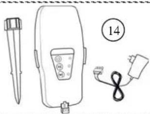
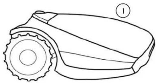
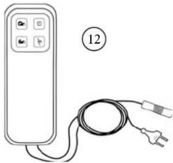
| 1 | Unit 8 | Plot ConnectorsUsed for connecting the Perimeter Wire to the Base Station | |
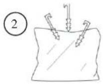
| 2 | Wire PegsUsed for securing the wire to the ground. | 9 | Base StationUsed by the unit to dock and charge when it is not mowing. |
| 3 | Perimeter WireUsed to create a virtual wall for your unit | 10 | Base Station StakesUsed for securing the Base Station to the ground |
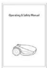
| 4 | Operating & Safety Manual 11 | Extension Cable15 meters (50 ft.), (Low voltage cable) | |
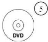
| 5 | DVDSetup and Operation Video. | 12 | Power BoxUsed to deactivate (halt) the automatic operation mode and reactivate it as needed. Also provides indication of the unit's status (Docking or Operating) and the Perimeter Wire's health. |
| 6 | RoboRulerUsed for setting the distance of the Perimeter Wire from the lawn edge. | 13 | Power Box MountUsed for fixing the Power Box to a wall (including Screws and dowels). |
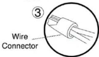
| 7 | Wire ConnectorsUsed for splicing wires (as needed) | 14 | Perimeter Switch (incl. Power Supply and Stake)Used to generate the signal in a Non-Base zone. The Perimeter Switch comes with models which are not supplied a Base Station and is available as an accessory. |
3. Planning Ahead
Getting your lawn ready for the unit is rather simple.
Still, as each lawn is unique, we recommend to read this chapter before starting to install the perimeter wire. Planning the wire route and drawing a sketch of the lawn, including all obstacles and Base Station location, will make it easier and will prevent mistakes during the setup.

Please watch the setup video on the unit DVD. This Video will walk you through the complete setup process.

Please complete reading this "Planning Ahead" chapter before you start the setup. It will guide you in finding the best locations for the Base Station, Power Box, and for the Perimeter Wire.
3.1 Planning the Perimeter Wire's Layout
The Perimeter Wire functions as an “invisible wall” for the unit. It sets the boundaries of lawn zones and it surrounds specific areas where you do not want the unit to enter. The Perimeter Wire is held to the ground with small pegs, supplied with the unit. Soon after settling, the wire will become invisible under the growth of new grass.
As soon as the unit starts operating, it turns on a signal that runs along the Perimeter Wire. This signal keeps the unit within its working zones and away from preset demarcated areas.
3.2 Lawn Types: What does your lawn look like?
There are 2 basic types of lawns.
Your first task is to determine which type is yours.
○ Main Zone Only
The unit will simply mow this lawn within its set boundaries.
- Separated Zone
The unit will mow each zone separately. Its movement between zones is restricted. Thus, you will have to bring the mower from the Main Zone to the Separated Zone every time you want to mow it.
3.2.1 "Main Zone" Type Lawn
The “Main Zone” lawn consists of one whole area. It has no Sub-Zones and no Separated Zones.
If you answer "yes" to the all of the following questions, your lawn is a "Main Zone Only" type lawn:
- Is your grass area one continuous zone? And:
Are all areas of your lawn wide enough for the unit to navigate through effectively? (Min. 3 meters (10 ft.) wide at its narrowest point).

▶▶ If your lawn does not match this description, read the next Sections to find the style of your lawn.
▶▶ If your lawn is “Main Zone Only”, you can skip to Section 3.3 of this chapter to determine the Base Station location.
3.2.2 "Separated Zones" Type Lawn
If your lawn contains a Separated Zone as defined in this section, refer to Section 6.4.2 (Add Separated Zone - number p014 in the table).
“Separated Zones” type lawn consists of two or more zones that are not connected. The unit cannot drive between these zones.
If you answer "yes" to at least one of the following questions, your lawn is of the "Separated Zones" type.
- Are parts of your lawn separated by fences, sidewalks, or other objects that the unit cannot pass? Or
○ Are parts of your lawn separated by a gravel path or similar material that may damage the mower blade?
Or
o Are the zones of your lawn situated at lower or higher level?

If your lawn does not fit any of these descriptions, it is probably either a "Main Zone" type. Skip to Section 3.3 – Select Base Station and Power Box Location.
A lawn may consist of up to 2 Separated Zones.
■ The mower must be carried or driven to this area manually.

Types of Separated Zone setups:
A Separated Zone smaller than 100m² (1100 ft²)
○ Separated area that is smaller than 100m2 (1100 ft 2 ) can be covered in a single operation, thus, if possible, the separated area may be connected to the main area's Perimeter Wire (have the signal come from the Main Base Station).
Or
- It may have to have its own separate Perimeter Wire. In that case, it will have to be connected to a Perimeter Switch (optional accessory – see Chapter 12 - Accessories).
Or:
A Separated Zone larger than 100 m² (1100 ft²)
○ If a separated area is larger than 100m2 (1100 ft 2 ), then it requires more than a single operation to cover the area;
○ In such cases, an additional Base Station (optional accessory) should be installed in the Separated Zone, otherwise you will have to manually bring the mower several times to the Separated Zone in order to complete the mowing of the area.
Separated Zone Smaller than 100m²(1100ft²)

Separated Zone larger than 100m²(1100ft²)

3.3 Select Base Station Location
3.3.1 Base Station Location Guidelines
- Do not place the Base Station within 3 meters (10 ft.) after a corner (relevant for Internal setup only (section 3.3.2).
- The Base Station should be within 15m (50 ft.) of a power outlet (230V / 120V).
- If the lawn has more than one zone, place the Base Station within the largest zone.
■ Make the Base Station invisible to the street to avoid theft. - Select a shady spot. This will extend battery lifetime.
- Place the Base Station on a relatively level ground. Do not place it on a slope.
- Place the Base Station away from sprinkler heads.
There are two options to set the Base Station:
3.3.2 Internal Setup (on the lawn perimeter)
- Choose a place along the Perimeter Wire where you want to place the Base Station, based on the inputs given in paragraph 3.3.1.
- Place the Base Station in the direction shown in the figure to the right.
3.3.3 External Setup (off the lawn perimeter): At a corner
In this type of setup, the Base Station is located at one of the corners of the lawn, as shown in the figure at the right.
- Choose a corner where you want to place the Base Station outside of the lawn area.
- Place the Base Station, where its front side is touching the lawn edge or placed somewhat on the lawn.
- Continue to lay the perimeter wire as shown in the figure to the right, where it continues at least 10cm beyond the Base Station and turns back towards the lawn at a distance of 10cm from the other wire.
- The Base Station may be placed in a small shift to the right in order to allow smooth entry of the mower to the Base Station.
- You will have the opportunity to later adjust the Base Station position to confirm smooth entry.


3.4 Select Power Box Location
Consider the following in order to select the Power Box location:
- The Power Box will be connected to the Base Station using the 15m (50ft.) Extension Cable.
- Select a suitable location for the Power Box to be mounted on a wall near a power outlet.
- Locate it outside the lawn perimeter.
- Select an easily accessed spot.
- Select a dry and sheltered location.
■ The Power Box is to be mounted vertically.

The Power Box is suitable for Outdoor use. Yet, it should be placed in a sheltered, dry and well ventilated spot. The Power Box should not be exposed to direct sunlight or rain.
3.5 Planning the Perimeter Wire Layout
3.5.1 Objects insidelawn
- Objects such as flower beds, ponds, or small trees can be protected by designating "Perimeter Islands", which are demarcated areas of the lawn, where the unit does not enter.
- If the areas where obstacles are grouped closely together, they should be demarcated by a single, continuous Perimeter Island.
- Obstacles that are vertical, relatively rigid, and higher than 15 cm (6 inches), such as trees, phone or power poles, do not need Perimeter Island. The unit will turn when it collides with these obstacles.
3.5.2 Slopes
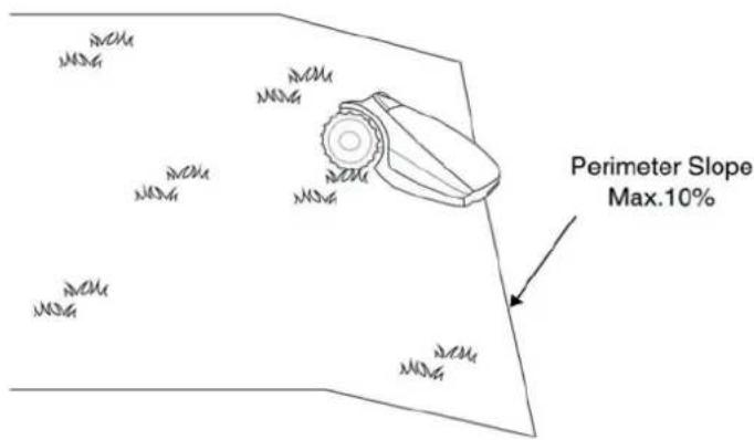
Slope on the perimeter
- The Perimeter Wire can be laid across a slope that slants less than 10% (10cm rise per 1m).
CAUTION! If the Perimeter Wire is laid across a slope steeper than 10%, it may cause the mower to slip, especially when the grass is wet, and to cross outside the wire.
However, if there is a barrier (e.g. fence or wall) that can protect the mower from slipping off, the Perimeter Wire can be set on that slope.

Slope inside the lawn
- The unit can mow areas inside the working area with a slope of up to 35% (35cm rise per 1m).
- Tip: If the mower tilts off the ground while climbing a slope, it is too steep. Exclude this steep area from the unit's cutting area.
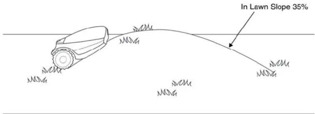
How to calculate the slope of your lawn?

How to calculate the slope of your lawn?
35 cm ( Elevation )/100 cm ( Length ) = 35 % ( slope )
3.5.3 Distances from the Edge (Pools, Ponds, Cliffs, etc.)
■ RoboRuler is used to measure the distance from the edge, where the wire is to be placed.

- In certain cases, near bodies of water such as pools and ponds, or great height differences such as cliffs, it is required to maintain a greater distance from the Edge (see Section 4.2.2).
4. Initial Setup
4.1 Preparations
Recommendation before you start:
During setup, you will insert pegs into the ground. To complete this task smoothly, we recommend not to do it while the grass is high and to water it before starting.
4.1.1 Getting Ready
Make sure all parts needed for setup are within reach. Have the unit box nearby, so all items are available.
In addition, you will need the following tools: A hammer, small flat screwdriver, Phillips screwdriver, Combination Pliers.

4.1.2 Installing the Power Box
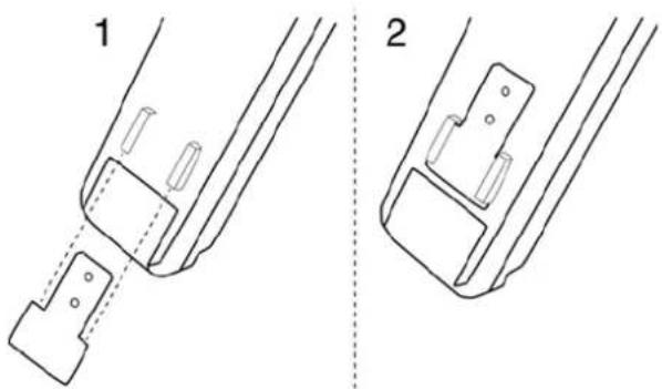
Mount the metal bracket onto a vertical surface with the provided screws. Make sure the narrow part with the holes facing up as shown in the figure to the right.
- Place the Power Box above the metal bracket and slide it into place along the vertical surface.
- Connect the Power Box to a regular power outlet (230V / 120V).
4.1.3 Charging the battery before the first operation
You can charge the unit battery while running the setup of the Perimeter Wire. This will ensure that the unit will be ready for operation when the setup is completed.
- The power of the mower is switched off when shipped from the factory. Press the 'Settings' button on the Operating Panel for 3 seconds to awake the mower.
- Connect the DC Cable coming from the Power Box to the Charging Socket at the rear side of the unit.
- Confirm the Battery LED on the unit is blinking, which is an indication of charging.
- Leave the unit connected to the Power Box while completing the setup of the Perimeter Wire.

4.2 Perimeter Wire Setup
Before you start the setup, you should have a plan for the Perimeter Wire layout and for the location of the Base Station. Your plan should consider the following:
o What type of lawn areas does your lawn have?
(Main Zone / Separated Zones / combination of types).
- Are there protected or excluded areas on the lawn? (Perimeter Islands).
o Are there any slopes that the unit should avoid?
o Are there edges of pools, ponds, cliffs etc., that need an extra distance from the Perimeter Wire?
4.2.1 Starting Point: Perimeter Wire at the Base Station area.
- Place the Base Station, according to your plan, as shown in the figure to the right.
- Do not place the Base Station within 3m (10 ft.) of a corner
- Select the roll of wire with a green plot connector attached to the end.
- Pull the plot connector and some wire out of the plastic covering.
! Do not remove the spool of wire from its covering. The plastic covering is the dispenser for the wire.
- Peg the beginning of the wire to the ground, where the Base Station will be located. Pegs are supplied in the unit's box.
- Pull out 30 cm (12 inches) of wire and leave it loose near the Base Station location. Later, at the end of the setup, this part of the wire will close the Perimeter Wire loop.
- Start laying the wire in an anticlockwise direction.
- Continue to pull the Perimeter Wire out of its covering, laying it loosely as you walk along the lawn edge.

! If you get to any area /object that needs care or special boundaries, make sure you carefully lay the Perimeter Wire as needed. The next sections deal with such special cases.
4.2.2 Laying the Perimeter Wire
○ The Perimeter Wire is secured to the ground by pegs supplied with the unit. Initially insert pegs every few meters and at corners. At this early stage set a minimum number of pegs. Later, after testing the wire setup, you will insert all necessary pegs.
○ After uncoiling some wire, before inserting pegs, use the RoboRuler to determine the distance of the wire from the lawn edge or obstacles.
- If the working area borders against a flat area, flower bed, small step (more than 1 cm), or a small elevation (up to 5 cm), the Perimeter Wire should be laid 20 cm (8 inches) inside the working area. This prevents the wheels from driving into a ditch.
- If the edge is sloped (max 10% is allowed) or is bordered with high obstacles such as a wall or fence, the Perimeter Wire should be laid at a distance of 28 cm (11 inches) from the obstacle.

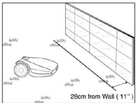
- If the working area borders against a flat path that lies level with the lawn, it is possible to allow the unit to run over the path. The Perimeter Wire should then be laid 10 cm (4 inches) from the edge of the path.
- When the working area is divided by a flat path that is level with the lawn, it is possible to allow the unit to run over the path. The Perimeter Wire can be laid under the pavement blocks or in the joint between them.
Important! The mower must never run over gravel, mulch, or similar material, which can cause the mower to slip and damage the blade.

IMPORTANT INFORMATION
If the working area is adjacent to a swimming pool, watercourse, slope greater than 10%, precipice higher than 50cm or a public road, the Perimeter Wire must be supplemented with a fence or the like. The height must then be at least 15 cm (6 inches). This will prevent the mower from ending up outside the working area under any circumstances.
If such a barrier exists, you may set the Perimeter Wire 28 cm (11 inches) from the barrier.
If there is no fence or the like, then lay the Perimeter Wire at minimum distance of 1.2m from the water.

○ Maintain a 45° angle in all left-turn corners when laying the wire along the perimeter. It is not necessary to maintain 45° angle on right-turn corners along the perimeter.
- Continue laying the wire, according to your plan. Gradually pull the wire out of its dispenser and lay it loosely as you are moving in an anticlockwise direction.

4.3 Perimeter Wire within the Working Area 4.3.1 Hard Obstacles
Obstacles that can withstand a collision, for example, trees or bushes higher than 15 cm, do not need to be demarcated by the Perimeter Wire. The unit will turn when it collides with this type of obstacle.

4.3.2 Perimeter Islands
Use the Perimeter Wire to demarcate areas inside the working area by creating islands around obstacles that cannot withstand a collision, for example, flower beds and fountains.
- Continue uncoiling the wire, moving from the edge towards the protected object.
o Peg the Perimeter Wire around the protected object in a clockwise direction.
- Complete bordering the island and return to the spot where you left the lawn's edge
- The wires leading to the Island and from it should be parallel and touching.
Therefore, peg both wires, to and from the island, together with the same pegs.
- The unit will not recognize these two wires. It will mow over them as if they do not exist.
- The unit will recognize the single blocking wire around the Perimeter Island and will not enter this area.

CAUTION! Setting the Perimeter Wire anticlockwise around the obstacle will cause the mower to drive into the island.
Keep the following distances when setting Perimeter Islands:
- The minimum distance of the Perimeter Wire from the protected area should be 28 cm (11 inches).
- If you need to protect a thin object, set the minimum radius of the Island to 35 cm (15 inches).
- Maintain a minimum of 1m (3.3 ft.) between adjacent islands.
- Maintain a minimum of 1m (3.3 ft.) between island wire and the Perimeter Wire.
- If protected objects are grouped closely together, demarcate them as a single Perimeter Island.

4.3.3 Setting a Narrow Pass
If the Narrow Pass is wider than 2m, and you want the unit to mow the area inside the Narrow Pass, then you can set the wire as shown in the figure below. Such a setup allows the mower to mow inside the Narrow Pass while mowing the inner part of the lawn, but prevents it from crossing between the zones.
![graph TD A["Sub-Zone"] --> B["Main-Zone"] B --> C["Perimeter Island"] C --> D["Main-Zone"] D --> E["Main-Zone"] style A fill:#f9f,stroke:#333 style B fill:#ccf,stroke:#333 style C fill:#cfc,stroke:#333 style D fill:#fcc,stroke:#333](/content/2026/05/1027935/images/df24b691faf72d791308ad2509ce9585a4347c7b69c40d4ae8f00c0967eceed9.jpg)
4.4 Fastening Perimeter Wire to the Ground
Before starting to lay the Perimeter Wire, it is recommended to cut the grass where the wire is to be laid. It will then be easier to attach the wire to the ground. The risk that the mower will damage the wire during the operation is reduced.
o It is not necessary to bury the Perimeter Wire, though you may do so, up to 5 cm (2 inches) deep.
o Pull the wire tight while hammering the peg all the way into the ground.

WARNING!
Protect your eyes! Protect your hands!
Use proper eye protection and wear appropriate work gloves when hammering the pegs.
Hard or dry ground may cause pegs to break when driving them in.
- Use a hammer to insert the pegs into the ground. - Insert the pegs at distances that will keep the wire down below the grass level and prevent the wire from becoming a tripping hazard (approximately 75 cm between pegs).
- The wire and the pegs will gradually become invisible under the growth of new grass.
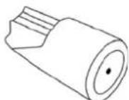
○ If an additional wire is required in order to complete the setup, connect it using the water-proof wire connectors supplied with the unit. (See Section 11.4 – Splicing the Perimeter Wire).


Use only the wire connectors supplied with the unit.
Neither Twisted cables, nor a screw terminal insulated with insulation tape are a satisfactory splice.
Soil moisture will cause the conductors to oxidize, which will later cause a broken circuit.
4.5 Back at the Base Station – Completing the Perimeter Wire Setup
Once the Perimeter Wire loop is completed and pegged to the ground, complete the setup by attaching the beginning and the end of the Perimeter Wire to the Base Station Head.
○ Hold both ends of the Perimeter Wire: the wire that started the loop is the one with an attached connector.
○ Twist the two wires.
○ Trim the end without the connector to make both of equal length. Remove any excess wire and strip back 5 mm (1/4 inches) of insulation from the wire end.
o Peg the two Perimeter Wires down to the ground using the same peg leaving enough loose wire. Twist together the two loose parts.
o Insert the end of the wire without the connector into the hole of the connector. Use a small flat screwdriver to tighten and secure this wire into the connector.


4.6 Placement and connection of the Base Station
- Place the Base Station on the Perimeter Wire as shown in the figure to the right.
o Align the center of the Base Station on the wire.

○ Attach the Perimeter Wire connector to the Base Station Head

○ After the Base Station has been positioned, insert 2 stakes into the Base Station holes as shown in the figure to the right. Only after the Base Station position will be tested, will you insert the 2 remaining stakes.
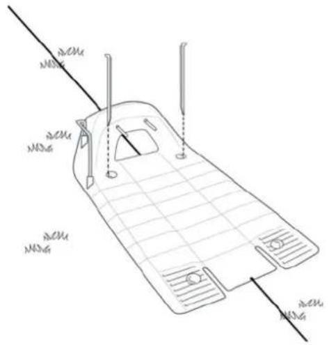
Laying and fastening Extension Cable

Safety – Avoid injury!
The Extension Cable from the Power Box to the Base Station should be securely fastened to the ground! It should never present a tripping hazard.
The Extension Cable should cross ONLY over soft surfaces.
It should not cross over hard surfaces (e.g. Sidewalk, driveway) where it cannot be securely fastened.

○ The 15m (50 ft.) Extension Cable is already attached to the Base Station Head, but if you need to disconnect it for any reason, remove the Base Station Head as shown in the figure to the right:
4.7 At the Power Box Location:
- Connect the DC Cable from the Power Box to the 15 m (50 ft.) Extension Cable.
- Connect the Power Box to a regular power outlet (230V / 120V).

- The Docking Indicator (1) will light up if the mower is in the Base Station.

- The Operating Indicator (3) will light up if the mower is not in the Base Station.
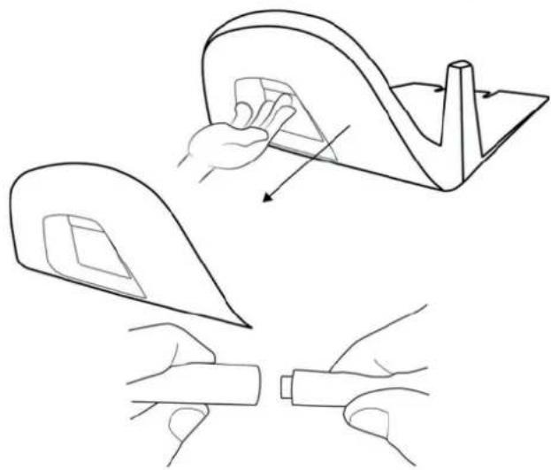

4.8 Setup in a Non-Base Zone
A Non-Base Zone is an area of the lawn that is not connected to a Base Station.
A Perimeter Switch should be installed in these areas.
When necessary, the Perimeter Switch can be easily moved to other zones.
4.8.1 Determining the Perimeter Switch Location
Consider the following in order to install the Perimeter Switch at an optimal location:
- The Perimeter Switch is to be installed outside the perimeter of the Non-Base Zone.
- Select a dry and sheltered location.
- The Perimeter Switch is to be mounted vertically.
- The Perimeter Switch is supplied with an indoor power supply. Choose a location close to a regular power outlet (230V / 120V).
Note - a rechargeable battery for the Perimeter Switch is available as an accessory (See Chapter 12 - Accessories).

4.8.2 Perimeter Switch placing options
- The Perimeter Switch connector is easily connected and disconnected. It allows for quickly switching from one zone to another.
- You may use the large stake, attached to the back of the Perimeter Switch, to easily insert it in and out of the ground.
- You may mount the Perimeter Switch on a vertical surface, such as a wall or deck railing. Use the three marks on the back of the Perimeter Switch cover.
4.8.3 Laying out the Perimeter Wire
The perimeter wire setup in a Base and Non-Base Zone are the same, except for the starting point:
- The Perimeter Switch is placed out of the area (at least 1 meter from the lawn).
- Start lay the Perimeter Wire from the Perimeter Switch location.
- Lay the Perimeter Wire from the Perimeter Switch to the lawn.

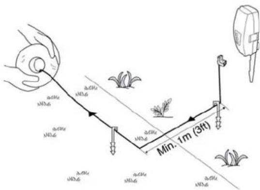

- Start laying the wire in anticlockwise direction.
- Once completing the Perimeter Wire loop, lay the wire back towards the Perimeter Switch.
- At the end of the Perimeter Wire loop, you have now two wires. Lay the two loose wires in the direction of the Perimeter Switch location and peg them to the ground using a single peg for both.
4.8.4 At the Perimeter Switch's location:
- Trim the ends of the loose wire to equal length and twist them together.
- Strip 5mm (0.2 inches) of insulation from the wire without the plot connector.
- Insert this wire end into the free hole in the connector and tighten the screws.


- Plug the perimeter wire connector into the Perimeter Switch.

- Hold the Perimeter Switch and squeeze its side tabs (1) to remove it from the back cover (2).
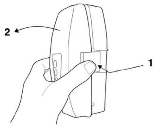
- Connect the Power Supply plug to the Perimeter Switch board. Replace the cover.
- Connect the power supply to a regular power outlet (230V / 120V).

IMPORTANT The Power Supply is for indoor use ONLY.
Choose a sheltered, dry, and well ventilated location that is NOT exposed to direct sunlight, water, or rain.
- Press the 'ON' button on the Perimeter Switch.
A small flashing green light next to the 'ON' button indicates the system is on and functioning correctly.
The control panel has other indicators: a disconnected or broken Perimeter Wire and a poor splicing (connection) in the Perimeter Wire.

The Perimeter Switch has an automatic shutoff feature. There is no need to turn it off after each use. The Perimeter Switch will shut itself off after 12 hours of operation. You may manually turn it off by pressing the ON/OFF button and holding it for 3 seconds. A beep will sound to indicate that the Perimeter Switch is off.
The Perimeter Switch can be operated by a rechargeable battery (available as an accessory).
5. Preparing the Unit
Before using the unit for the first time, you have to perform some simple preliminary settings. Once the preparations are complete, your unit will be ready to mow your lawn.
5.1 Adjust the Cutting Height
Blade Cutting Range: 15 - 60 mm (0.6 - 2.4 inches)
To adjust the cutting height of the blade, do the following:
CAUTION! ALWAYS TURN THE SAFETY SWITCH OFF BEFORE SERVICING BLADE!
- Lift the front side of the mower.
- Turn the knob while pushing it down.
• To raise the cutting height, turn anticlockwise.
• To lower the cutting height, turn clockwise
• The cutting height is displayed at the side of the mower.
5.2 One-Time Setup (Step by Step)
If the mower is in charging, remove it from the Base Station. Otherwise press the 'Settings' button to wake the mower.
Make sure the Power Box is plugged in.
The mower is now ready to perform the One-Time Setup process.
5.3 Using the Operating Panel
Use the buttons on the Operating Panel as follows:
- Press the 'Right' or 'Left' arrows until your selection is displayed.
- Press OK to select the value shown on the display.
- Press 'Back' (STOP) to go back or to cancel.
5.3.1 Choose Measurements Units and Formats
| Area / Distance Temp. Clock | |||
| EU | Meter | Celsius | 24 |
| US | Foot | Fahrenheit | 12 Hours (AM / PM) |
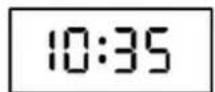
5.3.2 Set Day and Time
- Scroll to set the Day and press OK to confirm.
- Scroll to set the Time and press OK to confirm.


Mo Tu We Th Fr Sa Su
5.3.3 Main Zone Area
- Scroll to select an approximate area (EU- m² / US- ft²) of the Main Zone, where the Base Station is installed.
If an additional zone (Separated Zone) exists, do not include it in this area (it will be set separately).
Note - It is necessary to complete the above settings (5.2.1 - 5.2.3) in order to operate the mower. Every press on the STOP button will change the screen one step back in the process.
5.3.4 Test Base Station Position
- After setting the area, U001 (Test Base Station Position) is displayed.
- Place the unit inside the lawn, approximately 3 m (10 ft.) in front of the Base Station, facing the Perimeter Wire and press OK to start the test.
• The unit drives towards the Base Station:
If the mower does not start the test, then one of the following messages will be displayed:
E3 (No Wire Signal) – Confirm that the Power Box is connected to the power outlet and that the Extension Cable is connected at both ends, from the Power Box to the Base Station.
U029 (Swap wires in plot connectible Perimeter Wire has been connected in the opposite direction. Swap the wires at the plot connector.
- The unit will enter the Base Station, drive back, wait in front of the Base Station, and display U002 (Peg Base).
If U051 (Reposition Base Stationage is displayed:
- Move the Base Station slightly to align it with the Perimeter Wire.
- Check for any obstacles that may interfere with the mower's entrance to the Base Station.
- While 'U002' (Peg Base) is displayed, insert the remaining Stakes of the Base Station to secure it to the ground and press OK.


5.3.5 Test WirePosition
• U003 is displayed (Test Wire Position) – press OK.
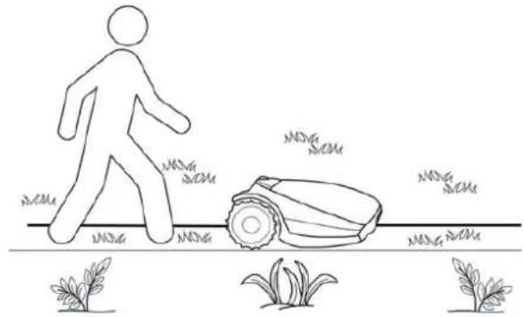
- The unit will follow the wire along the edge to test the wire position.
Walk alongside the unit while it is following the edge. Having completed the process, the unit will enter the Base Station and the setup process is completed.
If the mower collides with obstacles along the edge, the mower will stop and drive backwards with '
U052' (Adjust Wire) displayed:
- Move the wire slightly inward.
- Press OK to continue the Wire Test.
- If, at any point, you wish the mower to drive closer to the edge to enlarge the covered area, press Stop ('U003' is displayed - Test Wire Position):
- Move the wire slightly outward.
- Place the mower in front of the changed section of wire.
-
Press OK to continue the 'Test Wire Position' process.
-
If you want to quite the setup process, press the STOP button continuously for 3 seconds. The screen will change to the Main Display (current time).
- After completing the Test Wire Position, test the mower in Near Wire Follow mode to confirm it completes the drive near the wire smoothly, without acquiring any adjacent wire or hitting any obstacle on its way to the Base Station.
- If the mower fails to complete the Near Wire Follow smoothly to the Base Station, then reduce the Near Wire Follow Distance (Menu P004) and repeat the test until it will complete the drive smoothly.
5.3.6 After Setup is Completed
Once the wire setup is complete, drive additional pegs at a distance of approximately 0.75 m (2.5 ft.) apart.
- Use additional pegs in areas where there are bumps or dips in the lawn.
If needed, purchase extra pegs.
- Inspect the wire installation for tripping hazards.

6. Operation
6.1 Automatic Operation
During the One-Time Setup, you have defined the size of your lawn. The unit will automatically derive the required Mowing Time for your lawn.
- The One-Time Setup configures the unit to perform automatically the following cycle of operations:
- When the battery is fully charged the unit departs from the Base Station.
- The unit mows the lawn.
- It searches for the Base Station when the battery level gets low (The unit doesn't mow when it is searching for the Base Station).
- It recharges the battery and gets ready for the next scheduled operation.
- It continues mowing until it completes the required time for the lawn area (this is known as a Mowing Cycle).
Note: The unit mows the Edge only in the first mowing of each cycle. In the rest of the operations, the unit mows the lawn without the Edge.
- The unit stays at the Base Station during the default Inactive Time (All day Sunday and nighttime daily 23:00 to 06:00). Inactive Time may be changed – see Section 6.4.1.3.
o Mowing Time is derived from the set lawn Area.
Mowing Time may be changed using the Intensity menu - see Section 6.4.1.2.
o The unit mows the entire area Twice a week.
This frequency can be changed using the Interval menu - see Section 6.4.2 (p001 in the table).
Note!
The unit has the power to mow high grass. However when mowing high grass during the first use or the first mowing of the season, initially you will see uneven patches of grass.
Please be patient as it may take a few days to one week to overcome and bring the lawn to an even height and consistency.
6.2 Operating Panel
Operating Panel and buttons:

OK to choose / approve selection

6.3 Manual Operation
Manual Operation is used when mowing the lawn at unscheduled times.
To initiate Manual Operation when the unit is at the Base Station, press one of the buttons (except the STOP button) to show the display.
If the battery is fully charged and the mowing schedule is set to 'On', then the start time of the next operation is displayed, otherwise the current day and time are displayed.
Once the display is shown, choose the operation mode you want as provided in the table below:
| Operation Mode Child Lock is Off Child Lock is On | ||
| Mowing with Edge – Mowing the edge before starting to mow the inner area. It is recommended to use this mode once or twice a week, depending on how fast the grass is growing. | Press the 'Edge before mowing' (left arrow) button once | Press the 'Edge before mowing' (left arrow) button then press OK |
| Mowing without Edge – Mowing only the inner area without the edge. It is recommended to use this mode only in the first operation of each Mowing Cycle. | Press the 'Mowing' (right arrow) button once | Press the 'Mowing' (right arrow) button then press OK |
Note - if a Sub-Zone is defined, then once you choose the Operation Mode, then L1 (Main Zone) will be displayed. Use the arrow buttons to scroll and choose the required zone to be mowed and press OK.
6.4 Menu Options
There are several levels of menu options that can be set in your unit:
A. Basic Settings
B. Advanced Settings
6.4.1 Basic Settings
The Basic Settings are the most common menu options changed by the user. Each of the Basic Settings has an icon on the mower (refer to 6.2 – Operating Panel) that is lit to indicate the selected menu option.
o To change Basic Settings, press the 'Settings' button.
- Every press on the Setting button will move between the following 4 menu options:
6.4.1.1 Day and Time - Set the current Day and Time.
Press the 'Settings' button so the 'Day and Time' (Clock) icon is constantly lit. 'Day' is blinking → Scroll to the required day and press OK to confirm; 'Hours' is blinking → Scroll to the required hour and press OK to confirm; 'Minutes' is blinking → Scroll to the required min and press OK to confirm;
6.4.1.2 Intensity - Increase/decrease the number of operating hours needed to cover the lawn size.
Press the 'Settings' button twice until the 'Intensity' LED is constantly lit.
Use the scrolling arrows to change the Intensity and press OK to confirm;
The default Intensity is 100% and it can be changed from 50% to 150% .
Example: Intensity of 120%, means that the unit will run 20% more hours on the lawn.
6.4.1.3 Inactive Time - Set times when the mower will be inactive. Inactive operating times can be set for specific day(s) of the week, and for specific hours for all days in the week.
Inactive Day(s) defines the day(s) when the mower will be inactive (Default: Sunday).
Inactive Hours define the hours when the unit will not mow and stays in the Base Station (Default: 23:00-06:00)
IMPORTANT!
It is required to go through the entire Inactive Days and Hours sequence in order to save the settings. Pressing STOP before completing the whole sequence will not save the settings.
To change the Inactive Time, it is required to perform the following steps:
- Press the 'Settings' button 3 times until the 'Inactive Time' icon is constantly lit.
- The current Inactive Day(s) will constantly lit.
- Press the OK button; 'Mon' will start blinking.
- Press the RIGHT arrow to scroll to the day you want to set.
- Press 'OK' to toggle between 'Active' and 'Inactive' options for that day: The LED is lit - 'Inactive Day' (mower will stay in the Base Station all day).
The LED is off - available day for mowing. Press the RIGHT arrow to scroll to the next day you want to set
- Scroll through all the days to the right until the 'Inactive Hours' will start blinking.
- First set the time, which the Inactive Hours start and press 'OK'. Then set the time which the Inactive Hours will end.
- The unit will not operate during the Inactive Hours throughout all days of the week.
- If too many days/hours have been deactivated relative to the zone area, then 'E8' (Decrease Inactive Time) will be displayed – you need to decrease the number of inactive time so that the mower will have enough time to mow your lawn.
- To set the 'Inactive Hours' to 'Off' set the same time for the start and the end (i.e.: 00:00 to 00:00).
- Only one window of Inactive Hours can be set in the Basic Settings. To open an additional window of Inactive Hours use the Unit App.
6.4.1.4 Area - Update the size of the lawn in case it h changed.
- Press the 'Setting' button 4 times until the Area icon is blinking.
- Scroll to change the area and press 'OK' to confirm.
- If more than one zone is defined, then first scroll to select the zone you want to edit and set the area for that zone as described above.
Names of zones are as follows:
L1 - Main Zone
L2 - Separated Zone A
L3 - Separated Zone B
6.4.2 Advanced Settings
The Advanced Settings are additional menu options that are not changed very often and thus are not included in the Basic Settings.
- To change any option/feature in the Advanced Settings, press the 'Settings' button continuously for 3 Sec.
- 'P001' is displayed. Use the arrows to scroll to the setting you want to change, then press OK.
- Use the arrow button to change the setting and press OK to confirm.
- Scroll to change additional menu options or press STOP to go back to the main display.
Below are the Advanced Settings options:
| Screen | Setting Description | Options | |
| P001 | Interval(Default = 3) | Controls the Interval (frequency) of mowing cycles in the zone.ThedefaultInterval isTwice a week. It means that the unit will complete the entire mowing of your lawn twice a week (2 Mowing Cycles every week).The numbers in the menu represent the following:2 – Every two days3 -Twice a week7 - Once a week14 - Every two weeksIf there is more than one zone, the Interval can be set for all zones together or for each zone individually. You can choose All for all zones or scroll to the zone you want to change and change its setting.During off-season when the growth rate of the grass is slower, it is recommended to change the Interval to 'Once a Week' or 'Every Two Weeks'. This resting period helps the grass and prolongs the lifetime of the mower.Grass growth rate changes during the year (depending on temperature, grass type, fertilizing and etc.).High fertilization and favorable weather conditions may cause the grass to grow faster. In such cases, use the Interval option to decrease the time between cycles.The minimum Interval is Every 2 Days, but it is available only for relatively small areas, where the mower can complete mowing the area within 2 days. | 2/3/7/14 |
| P002 | Island(Default = OFF) | In rare cases, you may notice that the mower circles a Perimeter Island unnecessarily while searching for the Base Station.The Islands option helps overcome this situation. To avoid such cases, turn the Islands feature On. | On/ OFF |
| Screen | Setting Description Options | ||
| P003 | Near Wire Follow(Default = ON) | ·When the unit completes its operation, or when the 'Home' button instructs it to Go To Base, it drives itself to the Base Station.·The unit drives along the Perimeter Wire with a dynamic offset (not centered) to prevent wheel tracks along the same path. This return behavior can be turned off. | On/OFF |
| P004 | Max Near Wire Follow Distance(Default = changed based on the lawn area) | ·The maximum distance the unit will drive from wire when returning to the Base Station.·The distance does not represent actual units of measurement.·The offset Distance values range from 1 to 12. They represent different distances from the wire.·The higher the Distance setting, the smaller the probability of tracks along the perimeter.·Perimeter Islands that are relatively close to the Perimeter Wire or narrow passages may prevent the mower to complete its drive to the Base Station in 'Near Wire Follow' mode. In such cases decrease the distance to allow the mower to complete the drive to the Base Station. | 1-12 |
| P005 | Min Near Wire Follow Distance(Default = 1) | ·The minimum distance the unit will drive from wire when returning to the Base Station.·The larger the number, the bigger the distance the mower will drive from the wire while returns to the Base Station. | 1-5 |
| P006 | Rain Sensor(Default = ON) | ·The Rain Sensor feature halts operation on rainy or highly humid weather.·This is recommended for the health of the lawn. However, mowing wet grass does not present any technical problem. | On/OFF |
| P007 | Rain Sensor Sensitivity(Default = 25) | ·The unit detects rain when the current reading value is below the set Sensitivity value and postpones operation.·The higher the Sensitivity setting, the more sensitive the unit is to rain detection. | 0-30 |
| P008 | Sound(Default = ON) | ·Use the Sound option to turn all non-safety sounds off. | On/OFF |
| P009 | Base Station(Default = ON) | ·This option should be used for a Separated Zone which has a Base Station or when adding a Base Station to a model that does not have one.·If you have defined more than one zone, then select the relevant zone before changing the setting. | On/OFF |
| P010 | Child Lock(Default = OFF) | ·The Child Lock feature locks the buttons to prevent unintended operation, especially by children.·If the Child Lock is set to 'On', to operate the mower it is required to first press one of the operating mode buttons and then to press the OK button to confirm. | On/OFF |
| P011 | Anti-Theft Change PIN code | ·Allows changing of the Anti-Theft PIN code.·Enter a new code and then re-enter the new code for confirmation. | 0000 |
| P012 | N/A | ·N/A | N/A |
| P013 | Statistics(Default = OFF) | ·This menu is displayed only if P012 is set to 'On.·Enables to send the operation statistics from the mower to the manufacturer for diagnostics in case of problems. | On/OFF |
| P014 | Add Separated Zone | ·Enables the addition of a Separated Zone.·L2 is displayed for Separated Zone A - press OK.·Scroll to set the area of the Separated Zone and press OK. | L2100 |
| P015 | Remove Separated Zone | ·Enables the removal of a Separated Zone.·Choose the Zone you ant to remove and press OK. | L2L3 |
| P016 | Near Wire Follow Test | Enables to test the mower in the max 'Near wire Follow Distance' that is defined in menu P004.If the mower is not able to complete the drive in 'Near Wire' mode smoothly, then it is recommended to reduce the max distance set in menu P004. |
6.5 Operation in a Non-Base Zone (using a Perimeter Switch)
In order for the unit to operate in a Non-Base Zone, the Perimeter Switch has to be turned on and the mower should be inside the active perimeter area.
- Verify that the Perimeter Switch is connected to the zone to be mowed.
- Press the 'ON' button to turn on the Perimeter Switch.
- Drive/carry the unit to the lawn area.
- To initiate the operation, choose the operation mode you want, press the arrow buttons to choose the Zone you want to mow and press OK to start operation (refer to Section 6.3).
- When the unit completes the mowing, it will stay on the lawn. You will have to drive/carry it back to its place for charging.
7. Using The Power Box
7.1 Power Box Alerts
| Event Alert | |
| Docking Indicator is lit. The | mower is in its Base Station. |
| Operating Indicator is lit The | mower is not in its Base Station. |
| On/Off Button Indicator is lit.'OFF' will be displayed on themower. | Mowing schedule is Off. |
| Wire Indicator - Flashes and Beeps | The Perimeter Wire is cut, disconnected,or too long. |
| All Indicators flash | The mower did not return to the BaseStation after 4 hours of departure.When the mower is detected at the BaseStation, alerts will turn Off. |
| All Indicators flash and Buzzer sounds for 10 seconds. | The Anti-Theft option is set to On, andthe mower was removed from its BaseStation when it was not scheduled tooperate. |

Note - To stop an alert when sounding, press the On/Off Button.
7.2 Turn the Buzzer On/Off
- Press and hold the On/Off button for 10 seconds.
- A short beep indicates On.
- A flash indicates Off.
7.3 Disable the Automatic Operation
- This option is used to disable the predefined Automatic Operation of the unit. This option does not prevent Manual Operation (Chapter 6.3).
- Press and hold the On/Off button for 2 seconds.
'OFF' will be displayed on the mower:
○ If the unit is currently in the process of mowing:
- The unit will complete the current mowing cycle.
- After returning to the Base Station, the unit will not go out for its next scheduled operation.
• To Enable the Automatic Operation
o Press and hold the On/Off button for 2 seconds.
8. Charging
Laying and fastening the Extension Cable

Safety – Avoid injury!
Important: It is recommended to place the Power Box in a sheltered and dry location.
The Power Box should be well ventilated. Avoid exposure to direct sunlight or rain.
8.1 Charging During the Season
The Base Station is the primary charging source when the unit is docked and will maintain the optimal battery charge while awaiting departure.
8.2 Charging Out of Season
During out of season months, such as winter, it is required to:
- Fully charge the battery in the Base Station till the Battery indicator is green and lit constantly.
LED indicators for charging:
- Red is lit constantly – Charge the battery.
- Green is blinking – During battery charging.
- Green is lit constantly – Battery is fully charged.
- Remove the unit from its Base Station. Turn the Safety Switch off and store the mower in a room temperature.
- If the mower is stored for more than 3 months, it is required to recharge the battery every 3 months till the Battery indicator shows it is fully charged.
• The charging can be done in one of the following options:
-
Place the mower in the Base Station for charging.
-
Connect the unit directly to the Power Box as follows:
- Disconnect the DC Cable coming from the Power Box to the 15m Extension Cable and connect it to the rear side of the mower as shown in the figure to the right.
- Once the season starts, just place the unit in its Base Station to begin automatic operation.


9. Troubleshooting and User Messages
9.1 General Error Codes
The unit continuously monitors its operation. It produces error codes to assist you in running it smoothly.
A sticker containing the most common error codes is provided in the box. You can place it on the mower for your convenience.
E9* (See Troubleshooting in Manual) represents stops and error that are not very common, and thus they are not shown in the above Error Code Table. If E9 is displayed, press the RIGHT arrow to receive the Error Code reason, for which the mower has stopped and refer to the User Manual for more details.
- Usually, if the mower stops, an error code is displayed. This display stays on for 5 minutes. If you arrive later than those 5 minutes, the display will be blank.
- To wake the unit up and see the last error code displayed prior to stopping, press the OK button on the mower.
| Unit Error Codes Table | |
| E 1 | Stuck in Place |
| E 2 | The mower is Outside |
| E 3 | No Wire Signal |
| E 4 | Check Power |
| E 5 | Check Blade / Cutting Height |
| E 6 | Check Drive |
| E 7 | Front Wheel problem |
| E 8 | Decrease Inactive Time |
| E 9* | See Troubleshooting in Manual |
The following table displays all Error Codes and gives possible causes and corrective actions:
| Display | Message | Probable Cause/Event | Corrective Actions |
| E1 | Stuck in Place | - The unit got stuck in place. It cannot continue driving.- Drive wheel motors have been working under a severe load.- The unit has difficulty turning in place because the front wheel is blocked by a ditch or non-level ground. | - Remove the mower away from this particular location and restart operation.- Rectify the reason for it getting stuck.- Check the ground around the mower for ditches or non-level ground. Fill with dirt and level off.- Check if the drive wheels are free to rotate and nothing is blocking them.- Verify that the cutting height is not set too low for the grass condition - increase the cutting height if needed. |
| E 2 | The mower is Outside | - The Perimeter Wire is too close to the edge of the lawn.- The Perimeter Wire has been laid the wrong way around a perimeter island.- The lawn slope is too steep along the edge.- The unit does not succeed to turn in place at the edge and it I causing the mower to slip out of the designated area.- Automatic operation is initiated while the robot is placed out of the Perimeter Wire loop. | - Check that the Perimeter Wire is not too close to the edge - remove the wire towards the inner side of the lawn.- Confirm that the Perimeter Wire has been laid according to the instructions in the Manual.- Do not include areas with very steep slopes.- Verify that the cutting height is not set too low - Increase the cutting height.- Place the mower inside the lawn and renew the operation. |
| E 3 | No Wire Signal | - Power Box/Perimeter Switch is not turned on or not connected- The Perimeter Wire is not connected to the Base Station/Perimeter Switch.- The Perimeter Wire is cut. | - Make sure the Base Station is connected to the mains supply.- Disconnect the Power Box from the mains power and reconnect after 10 seconds.- Check that the low voltage cable between the Power Box and the Base Station is connected.- Check the LED indications on the Power Box.- Check the connection of the Perimeter Wire to the Base Station / Perimeter Switch.- Check the installation for cut wire. Repair broken cable with the waterproofed connector supplied in the box. |
| E 4 | Check power | - Power Box is not plugged in properly into the power outlet.- No power at the power outlet or the main power is shut off.- The mower or Base Station contacts are dirty.- Charging is not detected, although there is a physical contact between the mower and the Base Station contacts. | - Confirm Power Box is plugged into the power outlet.- Turn power on to the power outlet.- Check the power outlet using another appliance.- Clean the contacts with a brush or piece of cloth.- Confirm a good connection of the Power Box to the Base Station. |
| E 5 | Check Blade / Cutting Height | - Mowing motor has faced over-current conditions for too long as a result of high grass or an obstacle that is stuck or wrapped around the blade.- Something is preventing a blade from rotating freely (Accumulated grass clippings under the mowing deck; rope or similar object wrapped around mowing blade). | - CAUTION - Switch off the Safety Switch before checking the blade.- Inspect blade for foreign material or debris preventing rotation.- Clean out accumulated grass clippings using a wooden stick. |
| E 6 | Check Drive | - Grass or other object has wrapped around the drive wheel.- The drive motors have been working under severe load for too long. | - Check the drive wheels and remove the grass or other objects. |
| E 7 | Front Wheel Problem | - The Front Wheel has left the ground for too long during operation. | - If the unit has driven onto an obstacle, Switch off the Safety Switch, raising the front end: Remove or exclude the object from the mowing area.- If the unit is being used on a slope too steep for safe mowing, exclude this from the mowing area.- If high grass is preventing the front wheel from fully turning on the ground, raise the cutting height.- If the ground contains large holes or indentations where the front wheel can drop into when passing across, fill these areas with dirt and level off. |
| E 8 | Decrease Inactive Time | - Too many Inactive Days and/or Hours have been set for your lawn area. | - Decrease the number of Inactive Days and/or the number of Inactive Hours to allow the unit to complete mowing your lawn. |
| E 9 | See Troubleshooting in Manual | - E 9 is displayed for all other messages that are not listed in the above table. | - Press the 'Right arrow' button to receive the stop reason number and refer to the next table for more details about the stop reason, causes, and actions. |
9.2 Detailed Error Codes
If the above table (Section 9.1) does not give enough information to help solve the problem, then press the RIGHT arrow while the error code is displayed in order to receive a number that gives more details about the problem and refer to the table below:
| Display | Message | Probable Cause/Event | Corrective Actions |
| 0010 | Mow Overheat | - The mowing motor has been working under a severe load for too long. | - No need for action – the unit will renew automatically the operation after the mowing motor will cool down. |
| 0011 | Drive Overheat | - The drive motors have been working under a severe load for too long. | - No need to do anything.- The unit will renew the operation automatically as soon as the drive motor will cool down. |
| 0012 | No wire signal | - See E3 in the above table | |
| 0014 | Front wheel problem | - See E7 in the above table | |
| 0015 | Button pressed | - One of the operating panel buttons is constantly pressed. | - Press 'OK' to confirm the message and continue operation. This message is displayed to inform only. |
| 0016 | Low temperature | - Mower does not depart automatically from the Base Station when the ambiance temperature is lower than 5°C (41°F).- Information - When the temperature is below 5°C (41°F) the grass does not grow or grows very slowly.However Manual Depart is enabled. | - No need to do anything.- The unit will renew the operation automatically as soon as the ambiance temperature will rise above 5°C (41°F). |
| 0020 | Rain detected | - The operation is delayed as the unit detects rain. | - No need for action.- The message is displayed until the unit will not detect rain and then will start mowing. |
| 0021 | Check mowing height | - Mowing motor has faced over-current conditions for too long as a result of high grass or an obstacle that is stuck or wrapped around the blade.- Something is preventing a blade from rotating freely.Severe grass accumulation under the mowing deck, rope, or similar object is wrapped around mowing blade. | - CAUTION – Switch Off the Safety Switch before checking the blade.- Inspect the blade for foreign material or debris preventing rotation.- Clean out accumulated grass clippings using a wooden stick. |
| 0022 | Check mowing motor | - Mowing motor has faced over-current for too long in the Base Station before starting the operation. | - CAUTION – Switch Off the Safety Switch before checking the blade.- Remove the mower from the Base Station. Inspect the blade for foreign material or debris preventing rotation. |
| 0023 | Check power | - See E4 in the above table | |
| 0026 | Base problem | - The unit fails to enter the Base Station several consecutive times. | - Adjust the Base Station position.- Clean the contacts with a brush or piece of cloth. |
| 0027 | Start Elsewhere | - Drive wheel motors have been working under severe load during automatic or manual operation. | - Check to insure the mower is not stuck, causing the drive wheels to slip.- Check the ground around the mower for holes or indentations. Fill with dirt and level off.- Check if the drive wheels are free to rotate and nothing is blocking them.- Remove the mower away from this particular location and restart operation. |
| 0028 | Cross Outside | - The Perimeter Wire is too close to the edge.- The lawn slope is too big.- The unit does not succeed to turn in place at the edge and it causes the mower to slip out of the designated area.- The unit has slipped out of the Perimeter Wire lope because of sloping area or wet grass. | - Remove the wire towards the inner part of the lawn.- Do not include this area because of its steep slopes.- Fill holes and pits in the ground.- Increase the cutting height. |
| 0030 | Start Inside | - Automatic operation is initiated while the robot is placed out of the Perimeter Wire loop. | - Place the mower inside the lawn and renew the operation. |
| 0031 | Stuck in place | - See E1 in the above table | |
| 0060 | Check Intensity | - The Intensity you have set is too high for your lawn area. | - Decrease the Intensity you have set for the zone(s) in your lawn. |
| 0061 | Decrease Inactive Time | - See E8 in the above table | |
9.3 User Messages
The next table gives information about User Messages that can be displayed on the mower:
| Display Message / Description Action Required | ||
| BATT | Recharge Battery. Low battery voltage. Recharge the Battery. | |
| U001 | Test Base Station position. Displayed during the One-Time Setup. | Refer to section 5.2.4 in the User Manual. |
| U002 | Peg Base Station. Displayed during the One-Time Setup. | Refer to section 5.2.4 in the User Manual. |
| U003 | Test wire position. Displayed during the One-Time Setup. | Refer to section 5.2.5 in the User Manual |
| U004 | Test wire ended (during the One-Time Setup) Displayed only when using the Unit App. | No action is required. |
| U018 | Operation time is shorter than expected. Battery run time is too short. Replace Battery. | |
| U024 | Keep charging if not used. Displayed only if the mower is disconnected from a Charging Adaptor. | It is recommended to keep the mower connected to the Power Supply when not in use. |
| U025 | Switch Off before lifting | It is required to switch Off the System Switch before lifting and carrying the mower. |
| U029 | Change the wires in plot connector Displayed during the One-Time Setup. | Swap the wires at the plot connector. Refer to section 5.2.4 in the User Manual. |
| U032 | Switch on the System Switch. Displayed if the mower is connected to charging, but the System Switch is 'Off'. | Switch the System Switch to 'On'. |
| U041 | N/A | N/A |
| U042 | N/A | N/A |
| U043 | N/A N/A | |
| U044 | N/A | N/A |
| U051 | Reposition the Base Station position. Displayed during the One-Time Setup. | Refer to section 5.2.4 in the User Manual. |
| U052 | Adjust Wire Refer to section 5.2.5 in the User Manual. | |
| U062 | An alarm will soon be activated. | This message warns you to enter the PIN code before the Anti-Theft alarm will sound. |
| U064 | The Searching Base Station operation cannot be performed | When choosing the 'Home' button in a zone without a Base Station. |
| U086 | Waiting for the signal... The unit has stopped the operation. It does not detect a signal. | Check the power to the Power Box. There may be an electrical power interruption. There is no need to do anything. The unit will renew operation as soon as the power is back on. |
| U087 | Mow motor overheat, Cooling... The mowing motor has been working under a severe load for too long. | No need for action – the unit will renew automatically the operation, as the mowing motor will cool down. |
| U088 | Drive motor overheat, Cooling... The drive motors have been working under a severe load for too long. | No need to do anything. The unit will renew the operation automatically as soon as the drive motor will cool down. |
9.4 Fault Symptom
The next table will give details and possible causes of other faults, that do not provide error codes. If a fault cannot be dealt with using these tables, please call your service provider.
| Problem Encountered | Probable Cause/Event Corrective Actions | |
| Poor quality of mowing | - Dull blade | - Replace blade. |
| - The grass is too high in relation to the set cutting height. | - It is recommended to cut less than a 1/3 of the green part of the grass.- Set the cutting height to a higher position and then successively lower.- If it is during a fast growing season - change the Interval (refer to Section 6.4.2 - P001). | |
| - The grass is wet and causes accumulation of grass clippings around the blade. | - For best cut, operate the unit when the grass is dry. Do no to mow in the early morning hours.- Switch Off the Safety Switch and use heavy gloves to clean and remove the grass clippings. | |
| Mower doesn't find the Base Station | - There is a Perimeter Island or a Narrow Passage that prevents the mower to complete its drive towards the Base Station in Near Wire Follow mode. | - Reduce the Near Wire Follow Distance in the Settings menu from the default 7. |
| The unit is noisy and vibrates | - Damaged or unbalanced blade | - Check if the lawn is free from branches, stones or other objects that can damage the blade.- Replace the blade |
| Mower does not dock properly and sometimes misses the Base Station contacts | - Height differences between the lawn and the Base Station surface. | - Fill some ground to flatten the lawn to the Base Station to allow smooth entrance. |
| - The wire underneath the Base Station is not tight and placed in the middle of the Station. | - Confirm the wire underneath the Base Station is straight, tight, and centered below the Base Station. | |
| - The Base Station is set up on a side slope. | - Move the Base Station to a relatively level ground. | |
| - The Base Station is placed too close to the corner of the lawn | - Move the Base Station so it is not within 3 meters from a corner. | |
| Uneven mowing results | - The time between operations is too long because of long inactive time windows. | - Minimize the Inactive Time windows to allow the unit to complete the Mowing Cycle faster and to achieve even mowing results. |
| - Grass is growing very fast. | - If it is during a fast growing season - change the Interval (refer to Section 6.4.2 - P001). | |
| - The shape of the lawn is complicated (Narrow Passages, obstacle and islands). | - In a complicated lawn more time is required for the lawn to achieve better mowing results.- Increase the Intensity (refer to Section 4.3.2.1). | |
| - The set area is smaller than the actual lawn size. | - Increase the zone area (refer to Section 4.3.3 Edit an existing Zone). | |
| The unit operates during Inactive Time. | - Wrong clock time is set in the mower. | - Verify that the time on the mower is set correctly.- Set the time (refer to Section 4.4.4). |
| - Reset the Inactive Time (refer to Section 4.3.1). | ||
| Cut wire indicator is flashing on Power Box | - The Extension Cable is disconnected or damaged between Power Box and the Base Station. | - Confirm the Extension Cable is plugged in and wire leads are firmly attached. |
| - Perimeter Wire is cut. | - Walk along Perimeter Wire.- Look for cuts or breaks in the wire.- Repair with the unit wire splice connectors. | |
| The poor connection indicator is flashing on Power Box | - Poor connections | - Check and repair all loose, poor, or corroded connections. |
| - Twisted cables, or a screw terminal which is insulated with insulation tape is not a satisfactory splice.- Soil moisture causes the conductors to oxidize. | - Use the connectors supplied in the box. They are waterproof and give a reliable electrical connection. | |
10. Product Specification
| RS 300 RS 400 | RS 600 | |||
| Max Lawn Size | 00 m3 | 400 m2 | 600 m2 | |
| Base Station Included Included Included | ||||
| Robot Dimensions 63 x 46 x 21 cm 63 x 46 x 21 cm 63 x 46 x 21 cm | ||||
| Package Dimensions 80 x 54 x 33 cm 80 x 54 x 33 cm 80 x 54 x 33 cm | ||||
| Robot Weight 10.3 kg 10.3 kg 10.3 kg | ||||
| Package Weight | 22 kg | 22 kg | 22 kg | |
| Cutting Width | 28 cm | 28 cm | 28 cm | |
| Cutting Height | 15-60 mm | 15-60 mm | 15-60 mm | |
| Mowing Power | 200 Watts | 200 Watts | 200 Watts | |
| Mowing Motors | DC Brush | DC Brush | DC Brush | |
| Noise Level | TBD | TBD | TBD | |
| Battery Type | 26V Lithium (LiFePO4) | 26V Lithium (LiFePO4) | 26V Lithium (LiFePO4) | |

Anti-Theft PIN Code
Write down your 4-digit Anti-Theft PIN code.
Return here, if you ever forget the code.
Unit Serial Number
11. Maintenance and Storage
11.1 Maintenance of the Mowing Deck
The unit is a dedicated mulching mower. It may accumulate clippings under the mowing deck, particularly when mowing wet or damp grass.

Warning!
Severe injury hazard!
Always turn the Safety Switch Off before lifting the mower.
The blade is very sharp. They can cause severe cuts or lacerations.
Always wear heavy work gloves when working with or around the blade.
NEVER, use a damaged or a broken blade. Use only a sharp blade.
- Inspect the underside of the mower periodically. Clean if necessary. - Carefully scrape the collected grass debris from under the mowing deck.
- Most grass accumulation can be removed using a small wooden stick or similar object. - You may remove the blade to gain better access to the mowing chambers.
IMPORTANT
Do not place the mower upside down.
Instead, lean the mower against a surface to gain access to the mowing deck area.
IMPORTANT
NEVER use a water hose or any type
of liquid to clean the underside of the mower. Liquids can damage components.
Use only damp or wet cloth to wipe the surface clean after scraping.


11.2 Maintenance of the Blade
- Examine the cutting blade for damage periodically.
- Use only a sharp blade. Replace any damaged blade.
- Replace the blade once a year between seasons.
CAUTION! ALWAYS TURN THE SAFETY SWITCH OFF BEFORE SERVICING BLADE!

IMPORTANT
Sharpening of the blade is not
recommended, as it may create difficulties in balancing.
To remove the blade:
- Insert the clamp side of the Blade Removal Tool into the open slits beside the locking tabs on either side of the blade.
- Turn the Blade Removal Tool slightly so that the clamp resides on top of the locking tabs on either side.
- Squeeze the handle of the Blade Removal Tool. The locking tabs on each side of the blade will be pressed (1).
- Pull the blade assembly off, away from the mower (2)
- When reinstalling the blade, line up the mating splines and push until a firm click is heard, indicating a proper seating of the blade onto the shaft.

11.3 Disposing of the Old Battery Pack
IMPORTANT Do not place used batteries in your household trash. The battery must be collected, recycled, or disposed of in an environmentally sound manner. Return the old power pack to an approved battery recycler.
11.4 Splicing the Perimeter Wire
If the Perimeter Wire needs to be spliced, use the connectors supplied in the unit box. It is waterproof and gives a reliable electrical connection.
IMPORTANT
Before slicing the Primeter Wire, disconnect the Power Box from the power outlet.
-
Strip 1 cm (0.5 inch) of each wire end together and twist the stripped ends using pliers.
-
Insert the twisted wires into the splicing connector.
-
Screw the wire connector on the twisted wires. Make sure it is tightly secured.
IMPORTANT
Neither twisted cables, nor a screw terminal
insulated with insulation tape are a satisfactory splice. Soil moisture will cause such conductors to oxidize and will later lead to a broken circuit.


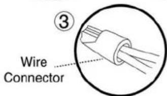
11.5 Maintenance of the Base Station Area
- Keep the Base Station entrance and area clean of leaves, sticks, twigs or any other debris that usually accumulate in such areas.
• NEVER spray a water hose directly towards the Base Station.
- Be careful when trimming around the Base Station with a powered weed trimmer as damage to the Extension Cable may occur.
- In the event of damage to any part of the Extension Cable, stop the use of the mower and the Base Station. Disconnect the Extension Cable and replace it.
12. Accessories
| BladeKeep a spare blade on hand.A sharp blade is important for safety and best cutting performance. | 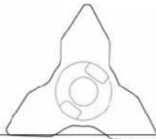 | BatteryUsed to replace the existing battery and refresh cutting capacity. | ||
| Perimeter WireFor larger lawns or additional zones. |  | Peg PackUsed to fasten the Perimeter Wire to the ground.For larger lawns or additional zones. |  | |
| Wire Repair ConnectorsUsed for repairing or splicing wires |  | Plot ConnectorsUsed for connecting the Perimeter Wire to the Base Station or Perimeter Switch. |  | |
| Base Station and Power BoxUsed for:○ Enabling multiple mowing cycles in a Separated Zone○ Upgrade a model without a Base Station to work in a fully automatic mode. |  | Remote ControlUsed to Manually drive and mow anywhere. Includes a Safety function to prevent accidental use. |  | |
| Perimeter SwitchFor zones that are not connected to the Base Station. |  | Batteries Pack for Perimeter SwitchPreferable for areas where electricity is not available or not close enough to the Perimeter Switch | 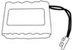 |
13. Tips for maintaining your lawn
Lawn care has never been so easy
Best time to mow
Mow your lawn when the grass is dry. This prevents the clippings from clumping and leaving piles on the lawn. Mow it late in the day rather than during the heat of the day.
Mowing frequency
Mow often, producing short, small clippings. During the active growing season the mowing frequency should be increased to once every 3-5 days, before the grass is too long. Short clippings decompose quickly and will not cover the grass surface. If the grass gets too high, raise the cutting height, mow, then gradually lower it over several mowings.
Cutting Height
Follow the "1/3 rule". Mow no more than 1/3 of the length of the grass.
Proper mowing will produce short clippings that will not cover up the grass surface.
You may have to cut the lawn more frequently, or double cut, when the lawn is growing fast, such as in the spring.

Water
Grasscycling reduces the amount of water needed by lawns since the clippings are about 80 – 85% water. Grasscycling slows evaporation losses from the soil surface, and conserves water. Most lawns need less water when Grasscycling.
Watering
Water your lawn between 4 a.m. and 8 a.m. in the morning, so water has time to soak into the soil before the heat of the sun causes evaporation.
Your lawn needs 1 to 1-1/2" (3-4cm) of water weekly. Deep watering allows grass to develop a deep root system, enabling the lawn to resist disease and drought.
Do not over water
Too much water is not only wasteful but can also increase turf growth, which requires more frequent mowing. Let the soil partially dry out between watering. Water when the top two inches of soil have dried out. Use an object such as a screwdriver to probe your soil and measure the depth of the moisture.
Fertilization
Grasscycling reduces the amount of lawn fertilizer needed because the clippings provide about 1/4 of a lawn's annual needs.
Blade
Keep your mower blade sharp. A sharp blade provides a clean, safe, and efficient cut. A dull mower blade will tear and shred the tips of the grass, which can provide an entry for disease organisms and weaken the grass plant. It is recommended to replace the mower blade once a year.
Thatch
Clippings and thatch are simply not connected. As mentioned previously, grass clippings are approximately 80-85 percent water with only small amounts of lignin, and decompose rapidly.
When we stop and think about it, golf courses, sports fields, and parks, have been mowing grass for years and recycling with no grass catchers.
A small amount of thatch (approximately 1/2 inch) is actually beneficial to a lawn. Grass clippings protect your lawn's root system from heat and water loss.
Garantie
1
2
3
4
5
6
7
Base Station and Power Box:
- Generates signal along the wire.
- Charges Robomow's battery.
Large trees: Robomow is allowed to bump
into them. at this size, the objects do not
require a Perimeter Wire around them
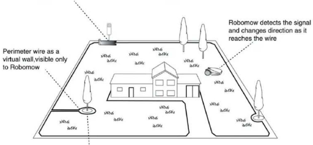
Tree surrounded by a groove, ditch or flower beds
requires a wire around it.
2.2 Driftsmetode


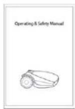
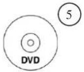


13
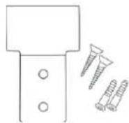

Separated Zone Smaller than 100m²(1100ft²)
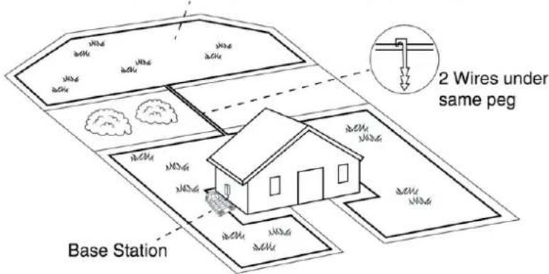
Eller:
Separated Zone larger than 100m²(1100ft²)


Skråning på plenen
How to calculate the slope of your lawn?
35 cm ( Elevation )/100 cm ( Length ) = 35 % ( slope )
3.5.3 Avstander fra kanten (basseng, dammer, klipper osv.)
4.1.2 Installere strømboksen


! Hvis du kommer til et område/objekt som trenger spesiell behandling eller spesielle grenser, sørg for at du legger grenseledningen forsiktig der den trengs. Det neste avsnittet omhandler slike spesielle tilfeller.
4.2.2 Legge grenseledningen

4.3.2 Grenseøyer

Bruk bare de ledningskoblingene som leveres med maskinen.
Verken vridde ledninger eller en skrueterminal isolert med isolasjonstape er en tilfredsstillende spleisekobling.


4.8 Oppsett i en sone uten base
En sone uten base er et område av plenen som ikke er koblet til en basestasjon.
4.8.3 Legge grenseledningen
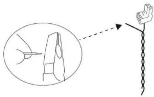
- Plugg grenseledningspluggen inn i grensebryteren.
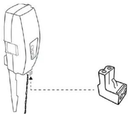
VIKTIG
5.3.5 Test ledningsplassering
6. Drift
6.1 Automatisk drift
A. Grunninnstillinger
B. Avanserte innstillinger
6.4.1 Grunninnstillinger


VIKTIG
11.3 Kassere den gamle batteripakken

1
2
3
4
5
6
7
Base Station and Power Box:
- Generates signal along the wire.
- Charges Robomow's battery.
Large trees: Robomow is allowed to bump into them. at this size, the objects do not require a Perimeter Wire around them

2.2 Princip provozu
2


4

6

7
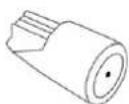
8

Modely se základnou
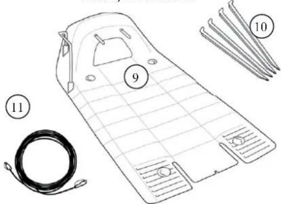
13


Modely bez
základny
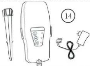
Nebo:

3.5.2 Svahy
Svah na obvodu
How to calculate the slope of your lawn?
35 cm(Elevation)/100 cm(Length) = 35 % (slope)


4.3.2 Ostrůvky

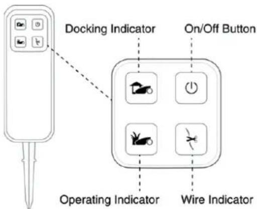
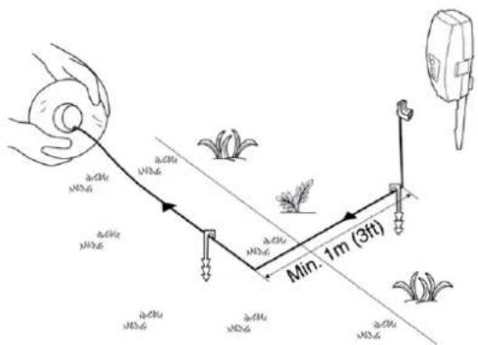
! DÜLEŽITÉ !
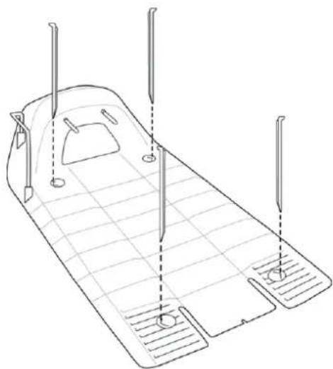
6. Provoz


11.2 Údržba nože
! DÜLEŽITÉ !
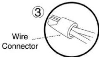
Base Station and Power Box:
- Generates signal along the wire.
- Charges Robomow's battery.
Large trees: Robomow is allowed to bump into them. at this size, the objects do not require a Perimeter Wire around them
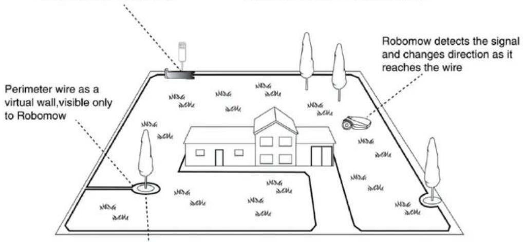
Tree surrounded by a groove, ditch or flower beds requires a wire around it.
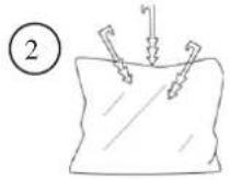
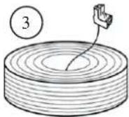

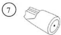
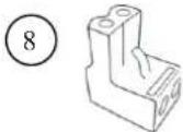
13


0:
Una zona separada mayor de 100 m² (1100 pies²)
Separated Zone larger than 100m²(1100ft²)
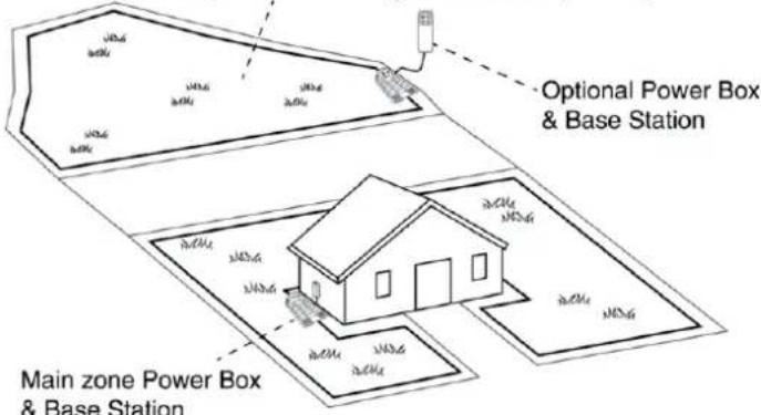


How to calculate the slope of your lawn?
35 cm ( Elevation )/100 cm ( Length ) = 35 % ( slope )


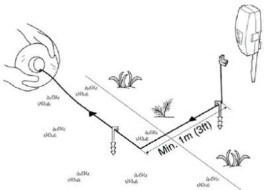
Mo Tu We Th Fr Sa Su

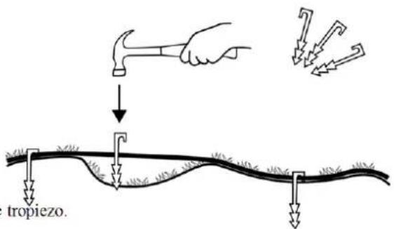
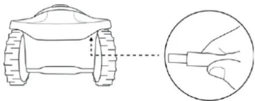


1
2
3
4
5
6
[Non-Text]
- Ovo je opasan aparat. Budite oprezni pri rukovanju i slijedite sve sigurnosne upute i upozorenja.
- Prije korištenja jedinice pažljivo pročitajte priručnik o rukovanju i sigurnosti.
- Tijekom rada postoji opasnost od bacanja ili leta predmeta.
- Tijekom rada budite na sigurnoj udaljenosti od jedinice. Ljude, a posebno djecu, kućne ljubimce i promatrače držite podalje od područja na kojem se jedinica koristi.
- Odsijecanje prstiju ruku ili nogu – rotirajuća oštrica kosilice. Rizik od ozljede zbog rotirajuće oštrice. Pazite na ruke i noge i nemojte pokušavati podići jedinicu s tog područja.
- Pokrenite uređaj za onemogućivanje prije nego krenete raditi na jedinici ili je podizati.
- Na jedinici se nemojte voziti.
Jedinicu ili bilo koji njen dio nemojte odlagati kao nerazdijeljeni komunalni otpad – potrebno ga je zasebno odlagati.
2.2 Način rada
Modeli s baznom stanicom

Modeli bez
bazne stanice
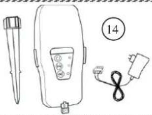
| 1 | Jedinica 8 | VodiliceKoriste se za povezivanje žice vanjskog ruba s baznom stanicom | |
| 2 | KolčićiKoriste se za osiguravanje žice na tlu. | 9 | Bazna stanicaKoristi je jedinica kao sidrište i mjesto za punjenje dok ne kosi. |
| 3 | Žica vanjskog krugaKoristi se za stvaranje virtualnog zida za vašu jedinicu | 10 | Držači bazne staniceKoriste se za osiguravanje bazne stanice na tlu |
| 4 | Priručnik za rad i sigurnost | 11 | Produžni kabel15 metara (50 ft.), (niskonaponski kabel) |
| 5 | DVDVideo za postavljanje i rad. | 12 | Kutija napajanjaKoristi se za deaktiviranje (zaustavljanje) automatskog načina rada i njegovo ponovno aktiviranje kad je to potrebno. Također osigurava status jedinice (sidrenje ili rad) te stanja žice vanjskog ruba. |
| 6 | RoboRulerKoristi se za postavljanje udaljenosti žice vanjskog ruba od ruba tratine. | 13 | Držač kutije napajanjaKoristi se za pričvršćivanje kutije napajanja na zid (uključujući vijke i zaglavnice). |
| 7 | Priključci žiceKoriste se za produljivanje žice (ako je potrebno) | 14 | Prekidač vanjskog ruba (uključujući napajanje i držače)Koristi se za stvaranje signal u zoni izvan baze. Prekidač vanjskog ruba dolazi s modelima koji nemaju baznu stanicu i dostupan je kao dodatna oprema. |
3. Planiranje
Ako vaša tratina ne odgovara ovom opisu, pročitajte sljedeće odjeljke da biste pronašli stil koji najbolje odgovara vašem stilu tratine.
Ako je vaša tratina vrsta “Samo glavna zona”, preskočite na odjeljak 3.3 ovog poglavlja da biste odredili položaj bazne stanice.
Vrste postavljanja zasebne zone:
Zasebna zona koja je manja od 100 m² (1100 ft²)
Ili:
Separated Zone larger than 100m²(1100ft²)

3.3 Odabir lokacije bazne stanice
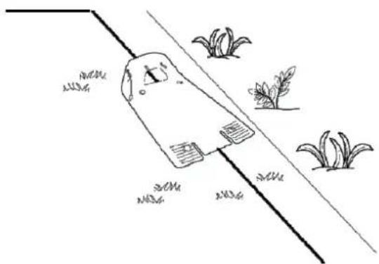

3.4 Odabir lokacije kutije za napajanje
Da biste odabrali lokaciju kutije za napajanje, razmislite o sljedećem:
How to calculate the slope of your lawn?
35 cm(Elevation)/100 cm(Length) = 35 % (slope)
3.5.3 Udaljenosti od ruba (bazena, jezeraca, strmina itd.)
4.1.2 Ugradnja kutije za napajanje
Metalno kućište postavite na okomitu površinu i učvrstite vijcima koje ste dobili. Pazite da uži dio rupa bude okrenut onako kako je prikazano na slici s desne strane.
- Kutiju za napajanje smjestite iznad metalnih držača i pomaknite je na mjesto duž okomite površine.
- Kutiju za napajanje povežite s običnom strujnom utičnicom (230 V / 120 V).
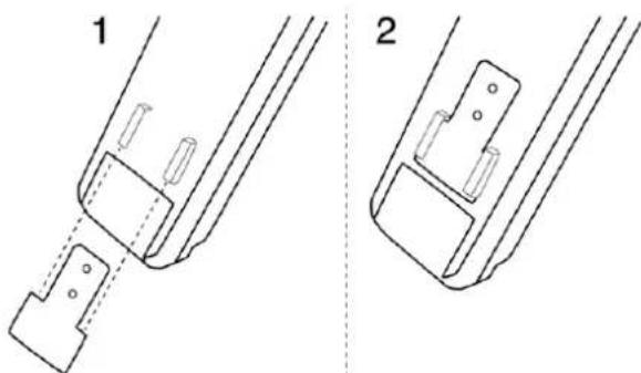
4.1.3 Punjenje baterije prije prvog pokretanja
Bateriju jedinice možete puniti dok pokrećete postavljanje žice vanjskog ruba. Tako ćete osigurati da jedinica bude spremna za rad do dovršetka postavljanja.
- Napajanje kosilice isključuje se prilikom isporuke iz tvornice. Da biste probudili kosilicu tri sekunde držite pritisnutim gumb "Settings" (Postavke) na upravljačkoj ploči.
- Povežite DC kabel koji izlazi iz kutije napajanje s utorom za napajanje sa stražnje strane jedinice.
- Potvrdite da LED žaruljica baterije na jedinici treperi, što je indikator punjenja.
- Ostavite jedinicu povezanu s kutijom za napajanje dok dovršavate postavljanje žice vanjskog ruba.
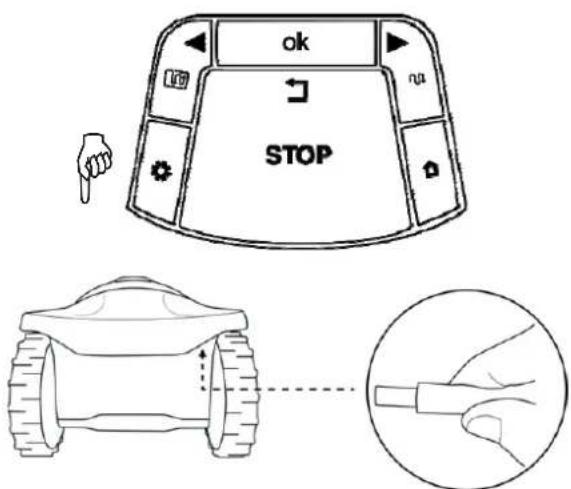
4.2 Postavljanje žice vanjskog ruba
Prije pokretanja postavljanja trebali biste imati plan za raspored žice vanjskog ruba i lokaciju bazne stanice. Vaš bi plan trebao uzeti u obzir sljedeće:
o Kakve vrste područja tratine postoje na vašoj tratini?
(Glavna zona / Odijeljene zone / kombinacija vrsta).
o Postoje li na tratini zaštićena ili isključena područja? (Otoci vanjskog ruba).
o Postoje li strmine koje bi jedinica trebala izbjegavati?
o Postoje li rubovi bazena, jezcraca, strmina itd. Kojima je potrebna dodatna udaljenost od žice vanjskog ruba?
- Ak o radna površina graniči s ravnim putem koji je u ravnini s tratinom, moguće je dopustiti jedinici da prijeđe preko puta. Žicu vanjskog ruba treba potom postaviti 10 cm (4 in.) od ruba puta.

4.6 Smještaj i povezivanje bazne stanice


4.8.4 Na lokaciji prekidača vanjskog ruba:
- Podrežite krajeve slobodne žice na jednaku dužinu i stegnite ih.
- Ogulite 5 mm (0,2 in.) izolacije sa žice na kojoj nema vodilica.

• Umenite taj kraj žice u slobodnu rupu u vodilici i stegnite vijke.

• Vodilicu žice vanjskog ruba umetnite u prekidač vanjskog ruba.

- Držite prek idač vanjskog ruba i stegnite njegove bočne jezičce (1) da biste ga skinuli s poklopca (2).


Mo Tu We Th Fr Sa Su


5.3.5 Testiranje položaja žice
• U003 se prikazuje (testiranje položaja žice) – pritisnite OK.
- Jedinica će pratiti žicu uz rub da bi ispitala položaj žice. Hodajte uz jedinicu dok ona prati rub. Nakon dovršetka postupka, jedinica će ući u baznu stanicu i postupak postavljanja je dovršen.
Ako se kosilica uz rub susretne s preprekama, zaustavit će se i krenuti unazad s prikazanom porukom "U052" (prilagodite žicu):
- malo pomaknite žicu unazad.
- Pritisnite OK da biste nastavili s ispitivanjem.

6. Rad
6.1 Automatski rad


11.2 Održavanje oštrice
- Povremeno provjerite ima li oštećenja oštrice.
- Koristite samo oštru oštricu. Zamijenite bilo kakvu oštećenu oštricu.
- Zamijenite oštricu jednom godišnje, između sezona.
OPREZ! PRIJE SERVISIRANJA OŠTRICE, UVIJEK UKLJUČITE SIGURNOSNI PREKIDAČ!

!VAŽNO! Ne preporučuje se oštrenje oštrice jer može izazvati poteškoće s balansiranjem.
Uklanjanje oštrice:
11.3 Odlaganje starog kompleta baterija
VAŽNO Istrošene baterije nemojte smještati u otpad iz domaćinstva. Baterije treba odlagati, reciklirati i bacati na ekološki održiv način. Stari komplet odnesite na odobreno mjesto za reciklažu baterija.
Base Station and Power Box:
- Generates signal along the wire.
- Charges Robomow's battery.
Large trees: Robomow is allowed to bump
into them. at this size, the objects do not
require a Perimeter Wire around them

Tree surrounded by a groove, ditch or flower beds
requires a wire around it.






13

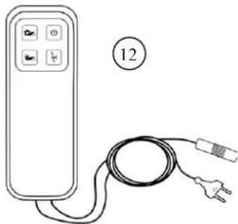
Alebo:
Separated Zone larger than 100m²(1100ft²)

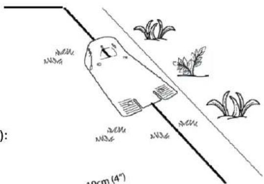

3.5.2 Svahy
Svah na obvode
How to calculate the slope of your lawn?
35 cm(Elevation)/100 cm(Length) = 35 % (slope)


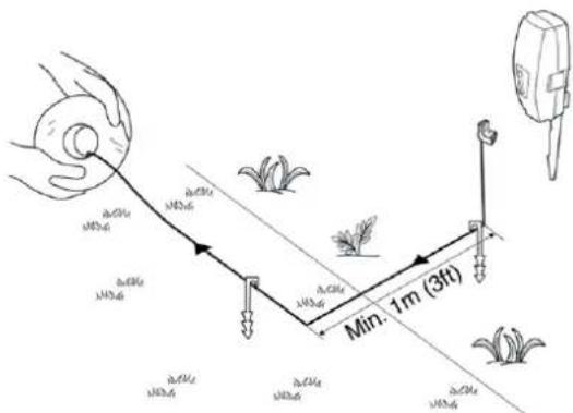

Obvodový spínač má funkciu automatického vypnutia. Nemusíte ho vypínat' po každom použití. Obvodový spínač sa sám vypne po 12 hodinách prevádzky. Môžete ho vypnút' aj ručne stlačením tlačidla ON/OFF (Zapnút/Vypnút') a podržanim na 3 sekundy. Ako signál vypnutia obvodového spínača zaznie pípnutie.

5.3.5 Test polohy drôtu
- Zobrazí sa hlásenie U003 (Test polohy drôtu) – stlačte OK.
6. Prevádzka


11.2 Údržba noža
! DÔLEŽITÉ

11.3 Zneškodnenie starej batérie

OX26 4UR Bicester, Oxfordshire

0 18 69 36 36 36

0 18 69 36 36 20
HU
MTD Hungária Kft
Dózsa György út 1
8248 Nemesvámos

06 88 51 55 00

06 88 50 55 20
NL
MTD Poland sp. z o.o.
UL. Ogrodnicza 1
84-252 Orle

058 57 20 701

058 57 20 699
RU
MTD Products Sweden AB
Sätunavägen 3
52141 Falköping

0 51 51 71 00

0 51 57 11 41 4
WOLF Garten









- 2.2 FUNKTIONSWEISE
- WICHTIGE INFORMATION
- BETRIEB
- WICHTIG
- INTRODUCTION AND SAFETY
- 1.1 INTRODUCTION
- WELCOME TO THE WORLD OF HOME ROBOTICS
- IMPORTANT
- 1.2 WARNING DECAL DEFINITIONS
- 1.3 SAFETY WARNINGS & PRECAUTIONS
- TRAINING
- PREPARATION
- OPERATION
- TRANSPORT
- USING REMOTE CONTROL (MANUAL MOWING)
- MAINTENANCE AND SPECIAL INSTRUCTIONS
- BATTERIES
- PRODUCT END OF USE
- 1.4 THE UNIT SAFETY FEATURES
- CHILD LOCK
- ANTI-THEFT / SAFETY GUARD
- LIFT SENSOR
- TILT SENSOR
- OBSTRUCTION SENSOR
- EMERGENCY STOP BUTTON
- SAFETY SWITCH
- SEALED BATTERIES
- BASE STATION / PERIMETER SWITCH AND PERIMETER WIRE
- KNOW YOUR UNIT
- 2.1 HOW THE UNIT WORKS FOR YOU
- 2.2 OPERATION METHOD
- WORKING METHOD
- PLANNING AHEAD
- 3.1 PLANNING THE PERIMETER WIRE'S LAYOUT
- 3.2 LAWN TYPES: WHAT DOES YOUR LAWN LOOK LIKE
- ○ MAIN ZONE ONLY
- SEPARATED ZONE
- 3.2.1 "MAIN ZONE" TYPE LAWN
- 3.2.2 "SEPARATED ZONES" TYPE LAWN
- TYPES OF SEPARATED ZONE SETUPS
- A SEPARATED ZONE SMALLER THAN 100M² (1100 FT²)
- A SEPARATED ZONE LARGER THAN 100 M² (1100 FT²)
- 3.3 SELECT BASE STATION LOCATION
- 3.3.1 BASE STATION LOCATION GUIDELINES
- 3.3.2 INTERNAL SETUP (ON THE LAWN PERIMETER)
- 3.3.3 EXTERNAL SETUP (OFF THE LAWN PERIMETER): AT A CORNER
- 3.4 SELECT POWER BOX LOCATION
- 3.5 PLANNING THE PERIMETER WIRE LAYOUT
- 3.5.1 OBJECTS INSIDELAWN
- 3.5.2 SLOPES
- SLOPE ON THE PERIMETER
- SLOPE INSIDE THE LAWN
- 3.5.3 DISTANCES FROM THE EDGE (POOLS, PONDS, CLIFFS, ETC.)
- INITIAL SETUP
- 4.1 PREPARATIONS
- RECOMMENDATION BEFORE YOU START
- 4.1.1 GETTING READY
- 4.1.2 INSTALLING THE POWER BOX
- 4.1.3 CHARGING THE BATTERY BEFORE THE FIRST OPERATION
- 4.2 PERIMETER WIRE SETUP
- 4.2.1 STARTING POINT: PERIMETER WIRE AT THE BASE STATION AREA
- 4.2.2 LAYING THE PERIMETER WIRE
- IMPORTANT INFORMATION
- 4.3 PERIMETER WIRE WITHIN THE WORKING AREA 4.3.1 HARD OBSTACLES
- 4.3.2 PERIMETER ISLANDS
- 4.3.3 SETTING A NARROW PASS
- 4.4 FASTENING PERIMETER WIRE TO THE GROUND
- WARNING
- 4.5 BACK AT THE BASE STATION – COMPLETING THE PERIMETER WIRE SETUP
- 4.6 PLACEMENT AND CONNECTION OF THE BASE STATION
- LAYING AND FASTENING EXTENSION CABLE
- SAFETY – AVOID INJURY
- 4.7 AT THE POWER BOX LOCATION
- 4.8 SETUP IN A NON-BASE ZONE
- 4.8.1 DETERMINING THE PERIMETER SWITCH LOCATION
- 4.8.2 PERIMETER SWITCH PLACING OPTIONS
- 4.8.3 LAYING OUT THE PERIMETER WIRE
- 4.8.4 AT THE PERIMETER SWITCH'S LOCATION
- IMPORTANT THE POWER SUPPLY IS FOR INDOOR USE ONLY
- PREPARING THE UNIT
- 5.1 ADJUST THE CUTTING HEIGHT
- 5.2 ONE-TIME SETUP (STEP BY STEP)
- 5.3 USING THE OPERATING PANEL
- 5.3.1 CHOOSE MEASUREMENTS UNITS AND FORMATS
- 5.3.2 SET DAY AND TIME
- 5.3.3 MAIN ZONE AREA
- 5.3.4 TEST BASE STATION POSITION
- 5.3.5 TEST WIREPOSITION
- 5.3.6 AFTER SETUP IS COMPLETED
- 6.1 AUTOMATIC OPERATION
- NOTE
- 6.2 OPERATING PANEL
- 6.3 MANUAL OPERATION
- 6.4 MENU OPTIONS
- 6.4.1 BASIC SETTINGS
- 6.4.2 ADVANCED SETTINGS
- 6.5 OPERATION IN A NON-BASE ZONE (USING A PERIMETER SWITCH)
- USING THE POWER BOX
- 7.1 POWER BOX ALERTS
- 7.2 TURN THE BUZZER ON/OFF
- 7.3 DISABLE THE AUTOMATIC OPERATION
- CHARGING
- LAYING AND FASTENING THE EXTENSION CABLE
- 8.1 CHARGING DURING THE SEASON
- 8.2 CHARGING OUT OF SEASON
- TROUBLESHOOTING AND USER MESSAGES
- 9.1 GENERAL ERROR CODES
- 9.2 DETAILED ERROR CODES
- 9.3 USER MESSAGES
- 9.4 FAULT SYMPTOM
- PRODUCT SPECIFICATION
- ANTI-THEFT PIN CODE
- MAINTENANCE AND STORAGE
- 11.1 MAINTENANCE OF THE MOWING DECK
- SEVERE INJURY HAZARD
- 11.2 MAINTENANCE OF THE BLADE
- 11.3 DISPOSING OF THE OLD BATTERY PACK
- 11.4 SPLICING THE PERIMETER WIRE
- 11.5 MAINTENANCE OF THE BASE STATION AREA
- ACCESSORIES
- TIPS FOR MAINTAINING YOUR LAWN
- LAWN CARE HAS NEVER BEEN SO EASY
- BEST TIME TO MOW
- MOWING FREQUENCY
- CUTTING HEIGHT
- WATER
- WATERING
- DO NOT OVER WATER
- FERTILIZATION
- BLADE
- THATCH
- GARANTIE
- 2.2 DRIFTSMETODE
- SKRÅNING PÅ PLENEN
- 3.5.3 AVSTANDER FRA KANTEN (BASSENG, DAMMER, KLIPPER OSV.)
- 4.1.2 INSTALLERE STRØMBOKSEN
- 4.2.2 LEGGE GRENSELEDNINGEN
- 4.3.2 GRENSEØYER
- 4.8 OPPSETT I EN SONE UTEN BASE
- 4.8.3 LEGGE GRENSELEDNINGEN
- VIKTIG
- 5.3.5 TEST LEDNINGSPLASSERING
- DRIFT
- 6.1 AUTOMATISK DRIFT
- 6.4.1 GRUNNINNSTILLINGER
- 11.3 KASSERE DEN GAMLE BATTERIPAKKEN
- 2.2 PRINCIP PROVOZU
- 3.5.2 SVAHY
- SVAH NA OBVODU
- 4.3.2 OSTRŮVKY
- DÜLEŽITÉ
- PROVOZ
- 11.2 ÚDRŽBA NOŽE
- UNA ZONA SEPARADA MAYOR DE 100 M² (1100 PIES²)
- 2.2 NAČIN RADA
- PLANIRANJE
- VRSTE POSTAVLJANJA ZASEBNE ZONE
- ZASEBNA ZONA KOJA JE MANJA OD 100 M² (1100 FT²)
- 3.3 ODABIR LOKACIJE BAZNE STANICE
- 3.4 ODABIR LOKACIJE KUTIJE ZA NAPAJANJE
- 3.5.3 UDALJENOSTI OD RUBA (BAZENA, JEZERACA, STRMINA ITD.)
- 4.1.2 UGRADNJA KUTIJE ZA NAPAJANJE
- 4.1.3 PUNJENJE BATERIJE PRIJE PRVOG POKRETANJA
- 4.2 POSTAVLJANJE ŽICE VANJSKOG RUBA
- 4.6 SMJEŠTAJ I POVEZIVANJE BAZNE STANICE
- 4.8.4 NA LOKACIJI PREKIDAČA VANJSKOG RUBA
- 5.3.5 TESTIRANJE POLOŽAJA ŽICE
- RAD
- 6.1 AUTOMATSKI RAD
- 11.2 ODRŽAVANJE OŠTRICE
- 11.3 ODLAGANJE STAROG KOMPLETA BATERIJA
- ALEBO
- SVAH NA OBVODE
- 5.3.5 TEST POLOHY DRÔTU
- PREVÁDZKA
- 11.2 ÚDRŽBA NOŽA
- DÔLEŽITÉ
- 11.3 ZNEŠKODNENIE STAREJ BATÉRIE
- HU
- NL
- RU
- WOLF GARTEN
Brand : Wolf Garten
Model : Ambition Robo Scooter 300
Category : Lawn mower