
Silence TP 2 - Desktop computer Baaske Medical - Free user manual and instructions
Find the device manual for free Silence TP 2 Baaske Medical in PDF.


| Product Type | Desktop Computer |
| Brand | Baaske Medical |
| Model | Silence TP 2 |
| Dimensions (W x D x H) | Approx. 200 x 400 x 450 mm |
| Weight | Approx. 12 kg |
| Power Supply | AC 100-240V, 50/60 Hz, 300W |
| Operating System | Windows 10 Pro (64-bit) |
| Processor | Intel Core i5 10th Gen or equivalent |
| RAM | 8 GB DDR4 |
| Storage | 256 GB SSD |
| Sound Level | < 20 dB(A) at idle |
| Intended Use | Medical environment (e.g., doctor's office, hospital) |
| Key Features | Silent operation, fanless design, medical-grade compliance |
| Connectivity | 4x USB 3.0, 2x USB 2.0, HDMI, DisplayPort, Ethernet LAN |
| Cleaning Instructions | Wipe with a soft, dry cloth. Do not use liquid cleaners. |
| Safety Certifications | CE, FCC, RoHS, IEC 60601-1 |
| Spare Parts Availability | Contact Baaske Medical support for spare parts |
| Reparability | Repairs should be performed by authorized technicians only |
| Warranty | 2 years (standard) |
Frequently Asked Questions - Silence TP 2 Baaske Medical
User questions about Silence TP 2 Baaske Medical
0 question about this device. Answer the ones you know or ask your own.
Ask a new question about this device
Download the instructions for your Desktop computer in PDF format for free! Find your manual Silence TP 2 - Baaske Medical and take your electronic device back in hand. On this page are published all the documents necessary for the use of your device. Silence TP 2 by Baaske Medical.
USER MANUAL Silence TP 2 Baaske Medical
All-in-one Medical Panel PC
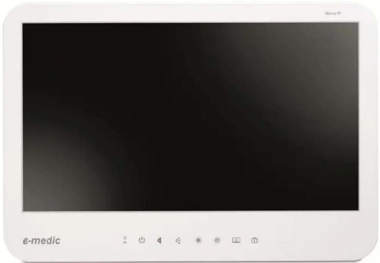
User Manual
Table of Contents
I. Safety & Regulatory Noce......2-9
A. Electronic Magnec Compatibility.... 2-6
B. Safety....7-8
C. Intended use....9-9
II. Product Basic 10-18
A. Specicaons 10-12
B. The Packing / Outline / I/O / Control Buons 13-15
C. Others....16-18
III. BIOS....19-29
I. Safety & Regulatory Noce
A. Electronic Magnec Compatibility
| Guidance and manufacturer's declaraon – electromagnec emissions | |||
| The e-medic Silence TP 2 & TP 1 are intended for use in the electromagnec environment specied below. The user should assure the products are used in such an environment. | |||
| Emissions test | Compliance | Electromagnec environment – guidance | |
| RF emissionsCISPR 11 | The e-medic Silence TP 2 & TP 1use RF energy only for its internal funcon.Therefore, its RF emissions are very low and are not likely to cause any interference in nearby electronic equipment. | ||
| RF emissionsCISPR 11 | The e-medic Silence TP 2 & TP 1 are suitable for use in all establishments, including domesc establishments and those directly connected to the public low-voltage power supply network that supplies buildings used for domesc purposes. | ||
| Harmonic emissionsIEC 61000-3-2 | |||
| Voltageuctuaons/icker emissionsIEC 61000-3-3 | |||
| Recommended separaon distances between portable and mobile RF communicaons equipment and the e-medic Silence TP 2 & TP 1 | |||
| The e-medic Silence TP 2 & TP 1 are intended for use in an electromagnec environment in which radiated RF disturbances are controlled. The user of the e-medic Silence TP 2 & TP 1 can help prevent electromagnec interference by maintaining a minimum distance between portable and mobile RF communicaons equipment (transmiers) and the e-medic Silence TP 2 & TP 1 as recommended below, according to the maximum output power of the communicaons equipment. | |||
| Rated maximum output power of transmier W | Separaon distance according to frequency of transmier m | ||
| 150 kHz to 80 MHz d = 1,2 | 80 MHz to 800 MHz d = 1,2 | 800 MHz to 2,5 GHz d = 2,3 | |
| 0,01 | 0,12 | 0,12 | 0,23 |
| 0,1 | 0,38 | 0,38 | 0,73 |
| 1 | 1,2 | 1,2 | 2,3 |
| 10 | 3,8 | 3,8 | 7,3 |
| 100 | 12 | 12 | 23 |
| For transmiers rated at a maximum output power not listed above, the recommended separaon distanced in meters (m) can be esmated using the equaon applicable to the frequency of the transmier, where P is the maximum output power rang of the transmier in was (W) according to the transmier manufacturer.NOTE 1 At 80 MHz and 800 MHz, the separaon distance for the higher frequency range applies.NOTE 2 These guidelines may not apply in all situaons. Electromagnec propagaon is aected by absorpon and reecon from structures, objects and people. | |||
| Guidance and manufacturer's declaraon – electromagnec immunity | |||||
| The e-medic Silence TP 2 & TP 1 are intended for use in the electromagnec environment specied below. The user of the e-medic Silence TP 2 & TP 1 should assure that it is used in such an environment. | |||||
| Immunity test | IEC 60601test level | Compliancelevel | Electromagnecenvironment –guidance | ||
| Electrostac | ?6 kV contact | ?6 kV contact | Floors should be wood, | ||
| discharge (ESD)IEC 61000-4-2 | ±8 kV air | ±8 kV air | concrete or ceramicle. If oors are covered with synthec material, the relave humidity should be at least 30 %. | ||
| Electrical fast transient/burstIEC 61000-4-4 | ±2 kV for power supply lines±1 kV for input/output lines | ±2 kV for power supply lines±1 kV for input/output lines | Mains power quality should be that of a typical commercial or hospital environment. | ||
| SurgeIEC 61000-4-5 | ±1 kV line(s) to line(s)±2 kV line(s) to earth | ±1 kV line(s) to line(s)±2 kV line(s) to earth | Mains power quality should be that of a typical commercial or hospital environment. | ||
| interrupons and voltage variaons on power supply input linesIEC 61000-4-11 | <5 % UT(>95 % dip in UT)for 0,5 cycle40 % UT(60 % dip in UT)for 5 cycles70 % UT(30 % dip in UT)for 25 cycles<5 % UT(>95 % dip in UT)for 5 sec | <5 % UT(>95 % dip in UT)for 0,5 cycle40 % UT(60 % dip in UT)for 5 cycles70 % UT(30 % dip in UT)for 25 cycles<5 % UT(>95 % dip in UT)for 5 sec | Mains power quality should be that of a typical commercial or hospital environment. If the user of the e-medic Silence TP 2 & TP 1 require connued operaon during power mains interrupons, it is recommended that the e-medic Silence TP 2 & TP 1 be powered from an uninterruptible power supply or a baery. | ||
| Power frequency(50/60 Hz)magnec eldIEC 61000-4-8 | 3 A/m | 3 A/m | Power frequencymagnec elds shouldbe at levelscharacterisc of atypical locaon in atypical commercial orhospital environment. | ||
| NOTE UT is the a.c. mains voltage prior to applicaon of the test level. | |||||
| Guidance and manufacturer's declaraon – electromagnec immunity | |||||
| The e-medic Silence TP 2 & TP 1 are intended for use in the electromagnecenvironment specied below. The user of the e-medic Silence TP 2 & TP 1should assure that it is used in such an environment. | |||||
| Immunity | IEC60601testlevel | Compliancelevel | Electromagnec environment –guidance | ||
| ConductedRFIEC61000-4-6Radiated RFIEC61000-4-3 | 3 Vrms150kHz to80MHz3 V/m80MHzto 2,5GHz | VrmsV/m | Portable and mobile RFcommunicaons equipment shouldbe used no closer to any part of thee-medic Silence TP 2 & TP 1,including cables, than therecommended separaon distancecalculated from the equaonapplicable to the frequency of thetransmier.Recommended separaondistance d = 1,2 d = 1,2 √80 MHz to 800 MHz d = 2,3 √800 MHz to 2,5 GHzwhere P is the maximum outputpower rang of the transmier inwas (W) according to thetransmier manufacturer and d isthe recommended separaon | ||
distance in meters (m).Field strengths from xed RF transmiers, as determined by an electromagnec site survey, a should be less than the compliance level in each frequency range. b Interference may occur in the vicinity of equipment marked with the following symbol: | |||||
| NOTE 1 At 80 MHz and 800 MHz, the higher frequency range applies.NOTE 2 These guidelines may not apply in all situaons. Electromagnec propagaon is aected by absorponand reecon from structures, objects and people. | |||||
| a Field strengths from xed transmitters, such as base staons for radio (cellular/cordless) telephones and land mobile radios, amateur radio, AM and FM radio broadcast and TV broadcast cannot be predicted theoretically with accuracy. To assess the electromagnec environment due to xed RF transmiers, an electromagnec site survey should be considered. If the measured eld strength in the locaon in which the e-medic Silence TP 2 & TP 1 are used exceeds the applicable RF compliance level above, the e-medic Silence TP 2 & TP 1 should be observed to verify normal operaon. If abnormal performance is observed, additional measures may be necessary, such as reorienng or relocang the e-medic Silence TP 2 & TP 1. b Over the frequency range 150 kHz to 80 MHz, eld strengths should be less than V/m. | |||||
B. Safety
 | ISO 7000-0434 : CAUTION, consult ACCOMPANYING DOCUMENTS. |
 | ISO 7000-1641 : Follow operang instrucons or Consult instrucons for use. |
 | IEC 60417 -5009 : STAND-BY. |
| IEC 60417-5031 : Direct current. | |
 | EU-wide legislaon, as implemented in each Member State, requires that waste electrical and electronic products carrying the mark (le) must be disposed of separately from normal household waste. This includes monitors and electrical accessories, such as signal cables or power cords. When you need to dispose of your display products, please follow the guidance of your local authority, or ask the shop where you purchased the product, or if applicable, follow any agreements made between yourself.The mark on electrical and electronic products only applies to the current European Union Member States. |
When networking with electrical devices, the operator is responsible for ensuring that the resulting system meets the requirements set forth by the following standards:
- EN 60601-1 (IEC 60601-1)
Medical electrical equipment
Part 1: General requirements for safety
- EN 60601-1-1 (IEC 60601-1-1)
Medical electrical equipment
Part 1-1: General requirements for safety
Collateral standard: Safety requirements for
Medical electrical systems
- EN 60601-1-2 (IEC 60601-1-2)
Medical electrical equipment
Part 1-2: General requirements for safety
Collateral standard: Electromagnec compatibility; Requirements and tests
Accessory equipment connected to the analog and digital interfaces must be in compliance with the respective naonally harmonized IEC standards (i.e. IEC 60950 for data processing equipment, IEC 60065 for video equipment, IEC 61010-1 for laboratory equipment, and IEC 60601-1 for medical equipment.) Furthermore all conguraons shall comply with the system standard IEC 60601-1-1. Everybody who connects additional equipment to the signal input part or signal output part congures a medical system, and is therefore, responsible that the system complies with the requirements of the system standard IEC 60601-1-1. The unit is for exclusive interconnecon with IEC 60601-1 cered equipment in the patent environment and IEC 60XXX cered equipment outside of the patent environment. If in doubt, consult the technical services department or your local representave.
C. Intended Use
The e-medic Silence TP 2 & TP 1 are designed to serve as a medical PC for general purpose usage in the hospital environment and for clinic review purpose. It could be used as a computer device for Surgical, Radiology, PACS (Picture Archiving Communicaton Systems), LIS (Lab Informaon Systems) and Electronic Medical Record applicaon.
It shall not be used in life-supporting systems.
WARMING: Crical diagnosc decision must not be based solely on images displayed by this device.
CAUTION: Use suitable moung apparatus to avoid risk of injury.
The user is not to touch SIP/SOPs and the paent at the same me.
The sound pressure level at the operator's posion according to IEC 704-1:1982 is no more than 70dB (A).
a) Grounding reliability can only be achieved when the equipment is connected to an equivalent receptacle marked “Hospital Only” or “Hospital Grade”.
b) Use a power cord that matches the voltage of the power outlet, which has been approved and complies with the safety standard of your parcular country.
c) CAUTION: This power adapter "Sinpro MPU101-105" is a forming part of this medical PC.
CAUTION:
Do not leave this equipment in an uncontrolled environment where the storage temperature is below -20° C ( -4° F) or above 60° C ( 140° F). This may damage the equipment.
II. Product Basic
A. Specicaons
| Main System | ||
| CPU: for TP 2 | . Support Intel Core i Ivy Bridge ultra low power CPU w/ BGA1023 package, 17W TDP (max.) and integrated graphics | |
| CPU: for TP 1 | . Support Intel Core i Ivy Bridge mobile CPU w/ PGA988 package, 35W TDP (max.) and integrated graphics | |
| Chipset | Intel BD82HM65 PCH | |
| Graphics | Intel HD Graphics HD 4000 | |
| Memory | 8GB maximum, x 2 DDR3 SODIMM, 1066/1333/1600MHz, 2GB/4GB/8GB | |
| Serial ATA | SATA3 x 2, 600MB/s transfer rate | |
| USB | x 7 (socket), USB 2.0 (x 4 external, x 3 internal) | |
| COM | x 6 (x 2 external, x 4 internal) | |
| Audio | Realtek ALC262 audio codec, 2+2 was amplifier | |
| LAN | Marvell 88E8071 Gigabit Ethernet x 2 | |
| BIOS | . AMI BIOS, 4M EEPROM . RTC wake up/Wake on LAN/Power on aer power failure/ PnP/ACPI | |
| Speaker | 1.5 was x 2 (front boom) | |
| LCD Panel | ||
| Size | 21.5" wide 16:9 | |
| Resoluon | Full HD 1920 x 1080 | |
| Brightness | 250 nits | |
| Contrast | 1000:1 | |
| Color numbers | 16.7M (6-bit x 3 + Hi FRC) | |
| Viewing angle | 170 (H) / 160 (V) | |
| Response me | 5 ms (R + F) | |
| Backlight | LED, 30,000 hours life me | |
| Touch Panel | ||
| Type | Front full at customized touch panel | |
| Technology | Resisve touch, 5-wire | |
| Light transmiance | >78% (at 550 nm wavelength) | |
| Hardness | 3H | |
| Touch stylus | No limitaon | |
| Resoluon | 4096 x 4096 | |
| Life me | 35 million acvaons | |
| Storage & Expansion | ||
| HDD | 2.5” SATA HDD drive bay x 1 + an-vibraon kit | |
| Expansion slot | PCI-E (x16) x 1 (oponal)Card size: 100 x 155 x 18/0.5 mm or 68 x 220 x 18/0.5 mmMini PCIe x 2 (52 pin card-edge type) | |
| I/O & Control Keys | ||
| USB | USB 2.0 x 4 | |
| COM | DB-9 x 2 (RS232, RS232/422/485) | |
| LAN | RJ-45 x 2, Gigabit | |
| Video-out | DVI-I x 1 | |
| Audio | Line-out, Microphone-in (3.5 mm phone-jack) | |
| Power input | DC-in x 1, 6V~32V | |
| Control keys | Front side, projected capacive typePower on/o, Brightness, Audio volume, Backlight on/o, Touch on/o | |
| Power | ||
| Power adaptor | External, 100 was, 90~264V AC in, 12V DC out, medical grade, (Sinpro MPU101-105) | |
| Power consumpon | TP 2 - 65 was (typical, without any add-ons)TP 1 – 75 was (typical, without any add-ons) | |
| Internal baery (oponal) | Rechargeable Lithium-Ion, 2S2P, 29.2Wh (avg.) / 27.74Wh (min.), for 20-25 minutes operang (approx.)Charge me: 2 hours (system o), 3.5 hours (system on) | |
| Mechanical & Environmental | ||
| Housing | Front: Full at design / Touch (standard), Glass (oponal)Rear: Plasc + I/O cover w/ anbacterial treatment | |
| Color | Housing: White . Control key icons: Grey | |
| IP rang | IP65 – front side | |
| Cooling | TP 2 - fanlessTP 1 - Variable speed smart fan design, < 30 dB (typical) | |
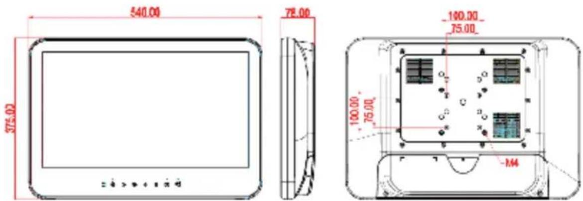
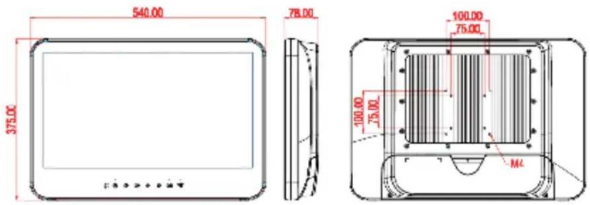
| Mounng | VESA 75 x 75 / 100 x 100 mm | |
| Kensington lock | Yes, x 1 at boom | |
| Dimension | 540 x 375 x 78 mm (W x H x D, w/o stand) | |
| Weight (net) | 7 Kg (approximate, w/o power adaptor) | |
| Temperature | Operang: 0°C to 40°C (32°F ~104°F)Storage/Transportaon: -20°C to 60°C (-4°F ~140°F) | |
| Humidity | Operang: 10% to 90%, non-condensingStorage/Transportaon: 10% to 90%@ 40°C, non-condensing | |
| Altudes | . Operang: up to 3,000 m (9,842 feet). Shipping: up to 12,192 m (40,000 feet) | |
| Pressure | . Operang: 700 – 1060 hPa. Storage/Transportaon: 186 – 1,060 hPa | |
| Vibraon | . Operang: 15g/0.53 oz, 11 ms, half sine wave. Non-operang: 50g/1.76 oz, 11 ms, half sine wave | |
| Shock | . Operang: 5 ~ 17 Hz ,Amplitude - 0.117 ~ 500Hz ,Acceleraon - 1.0G. Non-operang:10~55Hz/0.15g, 55~500Hz/2.0g | |
| Regulatory | . CE / Medical Safety 60601-1 3rdedion (EN 60601-1:2006)/ Medical EMC 60601-1-2:2007 | |
| Opons | ||
| Opons | . WLAN – mini PCIe module w/ internal antenna x 2 | |
| . Bluetooth 2.1 (USB) | ||
| . Baery pack | ||
| . Power adaptor w/ 2.4m or 3.6m DC cable | ||
| . Desktop stand | ||
B. The Packing / Outline / I/O / Control Buons
Basic packing list --
. The medical PC: e-medic Silence TP 2 (fanless) or TP 1 (smart fan)
. Power adaptor (Sinpro MPU101-105)
. AC power cord
. Touch stylus pen
. DVD tle (with drivers & user's manual)
. Screws (for rear cover VESA mounng)
Note: The contents may vary due to dierent opons or conguraon.
Outline dimension --
. e-medic Silence TP 1
. e-medic Silence TP 2
. The I/O interface (basic conguraon)
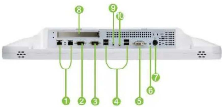
① LAN x 2
② RS232/422/485
③ RS232
4 USB x 4
⑤ DVI-I
6 Reset
⑦ DC-in
8 PCI-E/PCI expansion
9 Line-out
10 Micropone-in
. The control buons & LED indicators
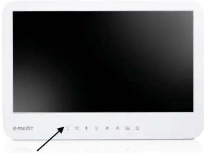
Control buons & LED indicators

- HDD indicator:
Dark - non-operang/stand-by Amber blinking - accessing
- Baery indicator:
Dark - non-operang Amber - operang Amber blinking - baery low
-
Power indicator: Dark - o Green - on
-
Power on/o buon
-
Speaker volume adjustment (-) button
-
Speaker volume adjustment (+) buon
-
LCD brightness (-) buon
-
LCD brightness (+) buon
-
LCD backlight on/o buon & indicator:
Dark - backlight on Green - backlight o
- Touch enable/disable buon & indicator:
Dark - touch enabled Amber - touch disabled
a. Press the buon for 5 seconds to disable or enable touch.
b. When the touch is disabled, aer 60 seconds, the touch will be enabled automacally.
C. Others
. To clean or disinfect the system
To clean or disinfect the system, to avoid any damage to the touch panel and the plasc housing, please check below chemical resistance table to ensure you disinfectant does not contain harmful ingredients.
We suggest to use Ethanol and do check with the personal who is responsible for disinfectng.
| Chemical | Touch panel |
| 10% Sodium Hydroxid | OK |
| Acetone | OK |
| Carbitol Acetate | OK |
| Cellosolve Acetate | OK |
| Ethanol / Alcohol | OK |
| Methylene Chloride | OK |
| Hydrochloric Acid - 6% | OK |
| Nitric Acid - 40% | Damage |
| Hexane | OK |
| Isopropanol (Isopropyl Alcohol)/Propanol | OK |
| Methyl Ethyl Ketone | OK |
| Heptane | OK |
| Toluene | Damage |
| Turpenne | OK |
| Vm & P Naptha | OK |
| Bleach (Sodium Hypochlorite, NaOCI) | Damage |
| Benzyl alcohol | Damage |
| Hydrogen peroxide | Damage |
| Chemical | Plasc housing |
| 40% Sodium Hydroxid | Damage |
| Acetone | Damage |
| Carbitol Acetate | Damage |
| Cellosolve Acetate | Damage |
| Ethanol / Alcohol | 500g load with 95% Alcohol--> OK |
| Methylene Chloride | Damage |
| Hydrochloric Acid - 6% | Damage |
| Hexane | Damage |
| Isopropanol (Isopropyl Alcohol)/Propanol | Damage |
| Methyl Ethyl Ketone | Damage |
| Heptane | Damage |
| Toluene | 500g load with 5% Cresol --> OK |
| Turpenne | Damage |
| Vm & P Naptha | Damage |
| Bleach (Sodium Hypochlorite, NaOCI) | 500g load with 10% Bleach--> OK |
| Benzyl alcohol | Damage |
| Hydrogen peroxide | Damage |
. The internal baery (oponal)
For those systems installed with internal baery, below is the specicaon.
| Baery cell type | Lithium-Ion rechargeable baery cell (2000mAh/cell) |
| Conguraon | 2S2P |
| Typical capacity | 4000mAh (for two cells) |
| Minimum capacity | 3800mAh (for two cells) |
| Nominal voltage | 7.3 V (average) |
| Energy | 29.2 Wh (typical) / 27.74 Wh (minimum) |
| Charge voltage | 8.4 V (typical) |
| Charge me | .System on (1A): 200 minutes.System o (2A): 120 minutes |
| Baery life | Discharge (> 10 minutes) for 300 mes, < 70% capacity le |
During the transportaon, we suggest you to disable baery
. Power o the system
. Disconnect the DC power (or AC power cord)
. Press the “speaker volume (+)” buon for 10 seconds
Next me when you connect the AC power and power on the system, the baery will be enabled automacally.
III. BIOS
Immediately aer powering on the system, during the POST (Power On Self Test) stage, press the key to enter the BIOS setup utility program.
Follow the menu & the keys instrucon to modify the BIOS conguraon & sengs.
Main --

Advanced --
![Aptio Setup Utility - Copyright (C) 2010 American Megatrends, Inc. Main Advanced Chipset Boot Security Save & Exit Legacy OpROM Support Launch FXE OpROM [Disabled] Launch Storage OpROM [Disabled] PCI Subsystem Settings ACPI Settings S5 RTC Make Settings CPU Configuration IDE Configuration Intel IGD…](/content/2026/05/1027851/images/4f564f1e767c2da347ec3c9b8bff6df46d1e06c348814d599ec5276543fb7eed.jpg)
Launch OpROM Support
Launch PXE OpROM
Enables or disables Boot Opon for Legacy Network Devices.
Launch Storage OpROM
Enables or disables Boot Opon for Legacy Mass Storage Devices with Opon ROM.
PCI Subsystem Sengs
PCI ROM Priority
In Case of mulple Opon ROMs (Legacy and EFI Compatible), species what PCI Opon ROM to launch.
PCI Latency Timer
Value to be programmed into PCI Latency Timer Register.
VGA Palee Snoop
Enables or disables VGA Palee Registers Snooping.
PERR# Generaon
Enables or Disables PCI Device to Generate PERR#.
SERR# Generaon
Enables or Disables PCI Device to Generate SERR#.
Relaxed Ordering
Enables or Disables PCI Express Device Relaxed Ordering.
Extended Tag
If ENABLED allows Device to use 8-bit Tag eld as a requester.
No Snoop
Enables or Disables PCI Express Device No Snoop opon.
Maximum Payload
Set Maximum Payload of PCI Express Device or allow System BIOS to select the value
Maximum Read Request
Set Maximum Read Request Size of PCI Express Device or allow System BIOS to select the value.
ASPM Support
Set the ASPM Level: Force L0 – Force all links to L0 State : AUTO – BIOS auto congure : DISABLE – Disables ASPM.
Extended Synch
If ENABLED allows generaon of Extended Synchronizaon paerns.
ACPI Sengs
Enables ACPI Auto Conf
Enables or Disables BIOS ACPI Auto Conguraon.
Enable Hibernaon
Enables or Disables System ability to Hibernate (OS/S4 Sleep State). This opon may be not eecve with some OS.
ACPI Sleep State
Select the highest ACPI sleep state the system will enter, when the SUSPEND buon is pressed.
S5 RTC Wake Sengs
Wake System with Fixed Time
Enables or disables system wake on alarm event. When enabled, the system will wake on the me specied.
Wake system with Dynamic Time
Enables or disables system wake on alarm event. When enabled, the system will wake on the current me+Increase minute(s).
CPU Conguraon
Hyper-Threading
Enabled for Windows XP and Linux (OS optimized for Hyper-Threading Technology) and Disabled for other OS (OS optimized for Hyper-Threading Technology)
Core-Mul Processing
Enable or Disable Core-Mul Processing mode.
Execute Disable Bit
XD can prevent certain classes of malicious buer overow aacks when combined with a supporting OS (Windows Server 2003 SP1, Windows XP SP2, SuSE Linux 9.2, RedHat Enterprise 3 Update 3.)
Limit CPUID Maximum
Disabled for Windows XP.
IDE Conguraon
ATA or IDE Conguraon
Select ATA or IDE conguraon.
Congure SATA AS
Select a conguraon for SATA controller.
HDD Acousc Power Ma
Opon to enable or disable HDD Acousc Power Management.
DiPM
Opon to enable or disable DiPM.
Intel IGD SWSCI OpRegion
DVMT Mode Select
Selects DVMT Mode used by Internal Graphics Device.
DVMT/FIXED Memory
Selects DVMT/FIXED Mode Memory size used by Internal Graphics Device.
IGD – Boot Type
Select the Video Device which will be acvated during POST. This has no effect if external graphics present.
LCD Panel Type
Select LCD panel used by Internal Graphics Device by selecng the appropriate setup item.
Panel Scaling
Select the LCD panel scaling opon used by the Internal Graphics Device.
GMCH BLC Control
Back Light Control Seng
BIA Control
Spread Spectrum clock
Hardware: Spread is controlled by chip;
Soware: Spread is controlled by BIOS.
TV1 Standard
TV2 Standard
Acve LFP
Select the Acve LFP Conguraon.
No LVDS:VBIOS does not enable LVDS.
INT-LVDS:VBIOS enables LVDS driver by Integrated encoder.
SDV0 LVDS:VBIOS enables LVDS driver by SDV0.
USB Conguraon
Legacy USB Support
Allows USB devices to be used in MS-DOS.
EHCI Hand-o
This is a workaround for OSes without EHCl hand-o support. The EHCl ownership change should be claimed by EHCl driver.
USB transfer me-out
The me-out value for Control, Bulk, and Interrupt transfers.
Device reset me-out
USB mass storage device Start Unit command me-out.
Device power-up delay
Maximum me the device will take before it properly reports itself to the HOST Controller.
'Auto' uses default value: for a Root port it is 100 ms, for a Hub port the delay is taken from Hub descriptor.
F71869 Super IO Conguraon
Serial Port 0 Conguraon
Set Parameters of Serial Port 0 (COM A).
Serial Port 1 Conguraon
Set Parameters of Serial Port 1 (COM B).
F71869 H/W Monitor
Monitor hardware status
Second Super IO Conguraon
Serial Port 1 Conguraon
Set Parameters of Serial Port 1 (COM C).
Serial Port 2 Conguraon
Set Parameters of Serial Port 2 (COM D).
Serial Port 3 Conguraon
Set Parameters of Serial Port 3 (COM E).
Serial Port 4 Conguraon
Set Parameters of Serial Port 4 (COM F).
Serial Port Console Redirecon
Serial Port Console Redirecon.
Chipset --
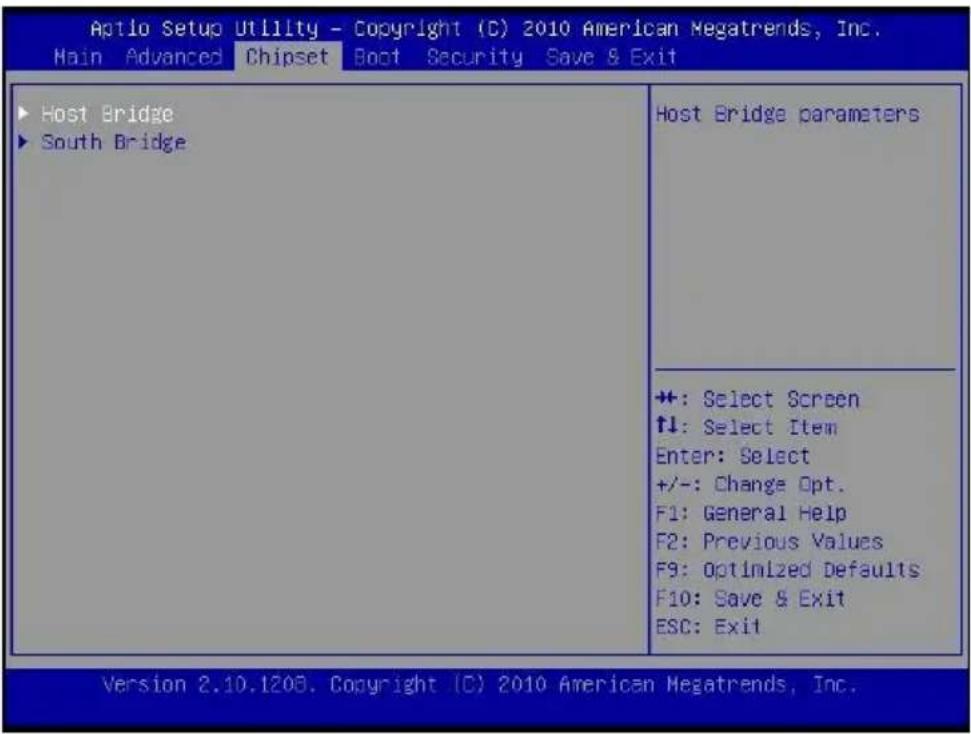
Host Bridge/South Bridge
This screen provides informaon on Host Bridge/South Bridge parameters.
Boot --
| Aptio Setup Utility - Copyright (C) 2011 American Megatrends, Inc. Main Advanced Chipset Boot Security Save & Exit | |
| Boot Configuration Setup Prompt Timeout Bootup NumLock State Boot Beep | Sets the system boot order B02 D00 is LAN#1 B03 D00 is LAN#2 Note: Bxx is dynamic bus address which depends on there is add-on card in system or not. |
| Quiet Boot Fast Boot | 07.65 |
| CSM16 Module Version | |
| GateA20 Active Option ROM Messages | [Upon Request] [Keep Current] |
| Interrupt 19 Capture | [Disabled] |
| UEFI Boot | [Disabled] |
| Boot Option Priorities | |
| Boot Option #1 | [B02 D00 Yukon Boot...] |
| Boot Option #2 | [B03 D00 Yukon Boot...] |
| Boot Option #3 | [ADATA USB Flash Dr...] |
| ++: Select Screen ↑↓: Select Item Enter: Select +/-: Change Opt. F1: General Help F8: Previous Values F9: Optimized Defaults F10: Save a Exit ESC: Exit | |
| Version 2.14.1219. Copyright (C) 2011 American Megatrends, Inc. | |
Setup Prompt Timeout
Number of seconds to wait for setup acvaon key. 65535(0xFFFF) means indenite waing.
Bootup Numlock State
Selects the keyboard NumLock state.
Quiet Boot
Allows you to determine whether to display the AMI Logo at system startup. Disabled displays normal POST message.
Fast Boot
Enables or disables the quick boot funcon to speed up the system boot-up process to shorten the waiing me for entering the operang system and to deliver greater eciency for daily use.
GateA20 Acve
This opon is useful when any RT code is executed above 1MB. Upon Request GA20 can be disabled using BIOS services. (Default)
Always Do not allow disabling GA20.
Opon ROM Messages
Sets display made for opon ROM.
Interrupt 19 Capture
Enables or disables Opon ROMs to Trap Int 19.
Boot Opon Priories
Species the sequence of loading the operang system from the installed hard drives.
Security –
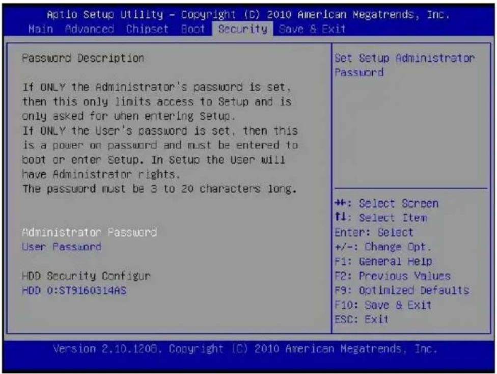
Enables or disables the security chip. It is recommended that you use this funcon with the Administrator/User password.
Save & Exit –
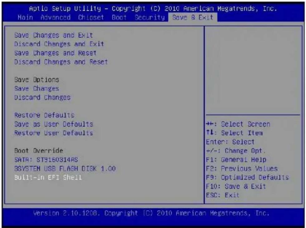
Save Changes and Exit
Exit system setup aer saving the changes.
Discard Changes and Exit
Exit system setup without saving any changes.
Save Changes and Reset
Reset the system aer saving the changes.
Discard Changes and Reset
Reset system setup without saving the changes.
Save Changes
Save the changes done so far to any of setup opons.
Discard Changes
Discard the changes done so far to any of setup opons.
Restore Defaults
Restore/load default values for all the setup opons.
Save as User Defaults
Save the changes done so far as User Defaults.
Restore the User Defaults to all the setup opons.
EFIGUI_FLASH
Press




- USER MANUAL
- TABLE OF CONTENTS
- SAFETY & REGULATORY NOCE......2-9
- PRODUCT BASIC 10-18
- BIOS....19-29
- SAFETY & REGULATORY NOCE
- SAFETY
- EN 60601-1-2 (IEC 60601-1-2)
- INTENDED USE
- CAUTION
- PRODUCT BASIC
- THE PACKING / OUTLINE / I/O / CONTROL BUONS
- BASIC PACKING LIST
- OUTLINE DIMENSION
- THE CONTROL BUONS & LED INDICATORS
- CONTROL BUONS & LED INDICATORS
- OTHERS
- TO CLEAN OR DISINFECT THE SYSTEM
- THE INTERNAL BAERY (OPONAL)
- BIOS
- MAIN
- ADVANCED
- LAUNCH OPROM SUPPORT
- LAUNCH PXE OPROM
- LAUNCH STORAGE OPROM
- PCI SUBSYSTEM SENGS
- PCI ROM PRIORITY
- PCI LATENCY TIMER
- VGA PALEE SNOOP
- PERR# GENERAON
- SERR# GENERAON
- RELAXED ORDERING
- EXTENDED TAG
- NO SNOOP
- MAXIMUM PAYLOAD
- MAXIMUM READ REQUEST
- ASPM SUPPORT
- EXTENDED SYNCH
- ACPI SENGS
- ENABLES ACPI AUTO CONF
- ENABLE HIBERNAON
- ACPI SLEEP STATE
- S5 RTC WAKE SENGS
- WAKE SYSTEM WITH FIXED TIME
- WAKE SYSTEM WITH DYNAMIC TIME
- CPU CONGURAON
- HYPER-THREADING
- CORE-MUL PROCESSING
- EXECUTE DISABLE BIT
- LIMIT CPUID MAXIMUM
- IDE CONGURAON
- ATA OR IDE CONGURAON
- CONGURE SATA AS
- HDD ACOUSC POWER MA
- DIPM
- INTEL IGD SWSCI OPREGION
- DVMT MODE SELECT
- DVMT/FIXED MEMORY
- IGD – BOOT TYPE
- LCD PANEL TYPE
- PANEL SCALING
- GMCH BLC CONTROL
- BIA CONTROL
- SPREAD SPECTRUM CLOCK
- TV1 STANDARD
- TV2 STANDARD
- ACVE LFP
- USB CONGURAON
- LEGACY USB SUPPORT
- EHCI HAND-O
- USB TRANSFER ME-OUT
- DEVICE RESET ME-OUT
- DEVICE POWER-UP DELAY
- F71869 SUPER IO CONGURAON
- SERIAL PORT 0 CONGURAON
- SERIAL PORT 1 CONGURAON
- F71869 H/W MONITOR
- SECOND SUPER IO CONGURAON
- SERIAL PORT 2 CONGURAON
- CHIPSET
- HOST BRIDGE/SOUTH BRIDGE
- BOOT
- SETUP PROMPT TIMEOUT
- BOOTUP NUMLOCK STATE
- QUIET BOOT
- FAST BOOT
- GATEA20 ACVE
- OPON ROM MESSAGES
- INTERRUPT 19 CAPTURE
- BOOT OPON PRIORIES
- SECURITY
- SAVE & EXIT
- SAVE CHANGES AND EXIT
- DISCARD CHANGES AND EXIT
- SAVE CHANGES AND RESET
- DISCARD CHANGES AND RESET
- SAVE CHANGES
- DISCARD CHANGES
- RESTORE DEFAULTS
- SAVE AS USER DEFAULTS
- EFIGUI_FLASH
Brand : Baaske Medical
Model : Silence TP 2
Category : Desktop computer