
DVG8640X - Range hood GORENJE - Free user manual and instructions
Find the device manual for free DVG8640X GORENJE in PDF.


| Product Type | Range Hood |
| Brand | Gorenje |
| Model | DVG8640X |
| Width | 60 cm |
| Dimensions (W x D x H) | 600 x 300 x 150 mm (approx.) |
| Weight | 12 kg (approx.) |
| Power Supply | 220-240 V, 50 Hz |
| Motor Power | 200 W |
| Maximum Extraction Rate | 620 m³/h |
| Number of Speeds | 3 |
| Noise Level (max speed) | 65 dB(A) |
| Lighting | 2 x LED, warm white |
| Filter Type | Aluminum grease filter |
| Control Type | Touch control panel |
| Installation Type | Built-in |
| Duct Diameter | 150 mm |
| Energy Class | A+ |
| Functionality | Exhaust or recirculation (optional charcoal filter) |
| Grease Filter Cleaning | Dishwasher safe |
| Safety Features | Overheat protection, automatic shut-off |
| Warranty | 2 years (depending on region) |
Frequently Asked Questions - DVG8640X GORENJE
User questions about DVG8640X GORENJE
0 question about this device. Answer the ones you know or ask your own.
Ask a new question about this device
Download the instructions for your Range hood in PDF format for free! Find your manual DVG8640X - GORENJE and take your electronic device back in hand. On this page are published all the documents necessary for the use of your device. DVG8640X by GORENJE.
USER MANUAL DVG8640X GORENJE
natural_image
Line drawing of a cabinet with ventilation grilles and a sloped roof (no text or symbols)Kitchen extractor hood Kaminhaube
Type
Typ:
DVG 6640 AX
DVG 8640 X
natural_image
Abstract geometric logo composed of nested triangles (no text or symbols)You are now a user of the newest generation kitchen extractor hood of DVG 8640 X / DVG 6640 AX type.
This hood has been designed and manufactured specially with a view to satisfying your expectations and it will certainly constitute a fitting element of a modern kitchen. The modern structural solutions and the newest technologies used in production of this hood guarantee its high effectiveness and good appearance.
Please read these instructions carefully before installing the hood. They will make you avoid mistakes during installation and operation of the hood. We wish you a lot of satisfaction from choosing our kitchen extractor hood.
| CONTENTS | |
| I Characteristics | |
| II Components | |
| III Technical data | |
| IV Operating conditions | |
| V Installation | |
| 1. Installation of the hood | |
| 2. Connecting to the power network and operation check | |
| 3. Setting the operation mode of the kitchen extractor hood | |
| 3.1. Setting the air extractor mode of operation of the hood | |
| 3.2. Setting the odour absorber mode of operation of the hood | |
| 3.3 Fan speeds | |
| VI Operation and maintenance | |
| 1. Operational safety | |
| 2. Operation | |
| 2.1. Control panel | |
| 2.2. Program function | |
| 3. Maintenance | |
| 3.1. Metal grease filters | |
| 3.2. Carbon filter | |
| 3.3. Lighting | |
| 3.4. Cleaning | |
I Characteristics
DVG 8640 X / DVG 6640 AX kitchen extractor hood was designed to remove kitchen fumes. It requires installation of a conduit discharging used air to the outside. The conduit (usually a pipe ∅150 or 120 mm) shall not be longer than 4-5 m. The hood can operate as an odour absorber after installation of an active carbon filter. In such case a conduit discharging used air to the outside is not necessary, but it is recommended to install an air exhaust guide.
The kitchen hood is an electrical appliance manufactured according to class II of shock protection.
It has its own lighting and an exhaust fan which can be set to one of three rotational speeds.
The hood was designed for permanent installation on a vertical wall over a gas or electric cooker.
II Components
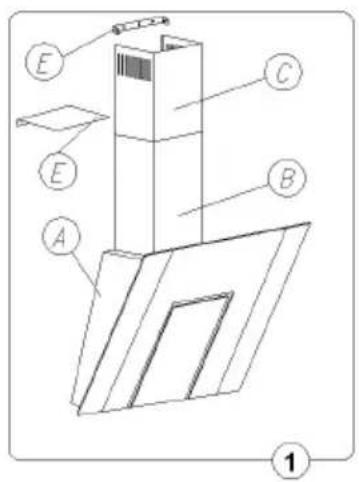
The hood consists of the following elements (Fig. 1):
- Hood body with a glass [A], equipped with glass, lights and the fan unit,
- The decorative cover consisting of the top funnel [C] and the bottom funnel [B],
- Wall hanger of the hood [D] and the hanger of the top decorative cover [E],
- Set of mounting plugs.
| III Technical data | |
| Characteristics | Hood typeDVG 8640 X / DVG 6640 AX |
| Supply voltage AC 230V 50Hz | |
| Fan motor 1 | |
| Lighting 2 x 20 W | |
| Number of grease filters 1 | |
| Fan speeds 4 | |
| Width [cm] 80 | |
| Depth [cm] | |
| Height [cm] | |
| Outlet [ø mm] 150 or 120 | |
| Capacity [m ^3 /h] Max 700 | |
| Power consumption [W] 240 | |
| Noise level [dBA] Max 54 | |
| Operational mode Extractor or absorber | |
| Colour INOX stainless steel, mat | |
IV Operating conditions
1. SAFETY PRECAUTION
Take care when the cooker hood is operating simultaneously with an open fireplace or burner that depend on the air in the environment and are supplied
by other than electrical energy, as the cooker hood removes the air from the environment which a burner or fireplace need for combustion. The negative pressure in the environment must not exceed 4Pa (4x10 -5 bar). Provide adequate ventilation in the environment for a safe operation of the cooker hood. Follow the local laws applicable for external air evacuation.
- The kitchen hood was designed for removal of kitchen fumes to the outside. It should be connected to an appropriate ventilation duct (do not connect the hood to any chimney, smoke or flue-gas ducts which are in use).
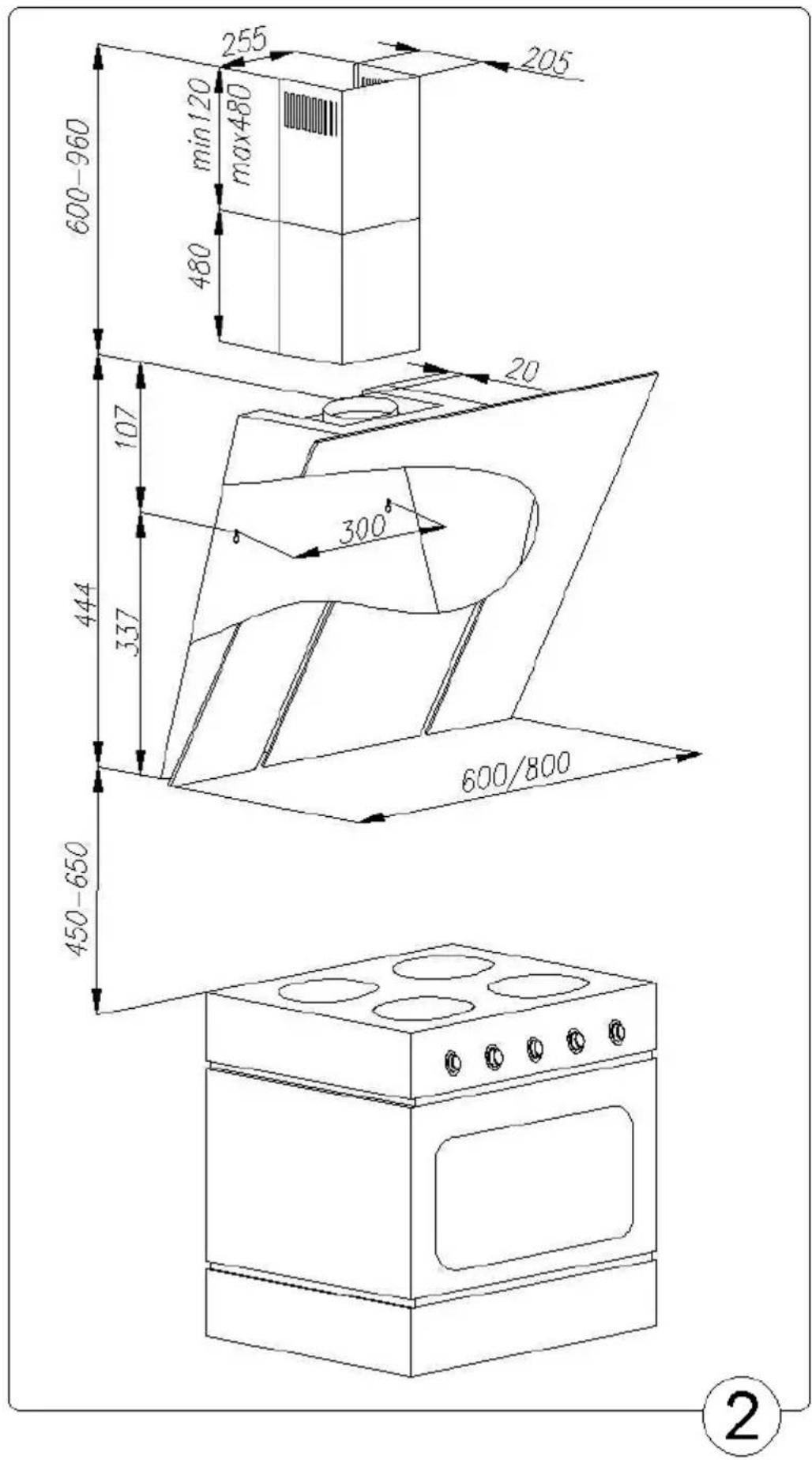
- The device shall be installed at the distance of at least 450 mm above the working top of an electric cooker and 550 mm - of a gas cooker.
- Do not leave open flame under the hood. When removing pots from the burners set the flame to its minimum level.
- Any food cooked in fat shall be constantly monitored, since overheated fat can ignite very easily.
- The grease filter of your kitchen hood should be cleaned at least every 2 months, because a filter soaked with grease becomes easily flammable.
- Pull the plug of the power cord from a wall socket before any cleaning, filter replacement or repair operation.
- If any other non-electric devices are used in the same room as the hood (e.g. liquid fuel ovens, flow-through or volumetric water heaters), it is necessary to provide appropriate ventilation (air supply). Safe operation is possible when during simultaneous operation of the hood and combustion devices dependent on air supply the negative pressure of not more than 0.004 milibar is maintained at the location of these devices inside the room (this point does not apply when the hood is used as an odour absorber).
- When connecting to 230V power supply network use an electric socket in working order
V Installation
To install the hood proceed as follows:
- Install the cooker hood [D] at the appropriate level.
- Connect the hood to the ventilation duct.
- Connect the hood to the power network.
- Install the wall hanger [E] at the appropriate level.
- Install the telescopic column of the masking cover.
1. Installation of the hood
a) Trace a vertical line on the wall to indicate the center of the cooker plate,
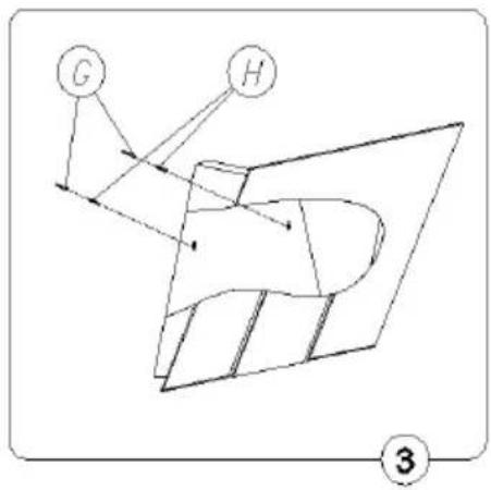
b) Hold a cooker hood [A] to the wall (Fig. 3), set it symmetrically in relation to the central line, with the distance between the holes in the profile and the cooker plate amounting to min. 787~mm , level the hood preliminarily, indicate the spacing of mounting holes on the wall,
c) Drill the holes as indicated on the wall, using drills of diameter corresponding to the attached expansion plugs, drive the plugs in and then screw the cooker hood body to the wall, and then tighten the screw [H]
d) Attach the telescoping column of the masking cover [A and B] on the mounted hood (Fig. 1)
e) Extend the top masking cover [C] (Fig. 1) to the required height, indicate its max. reach on the center line, remove the cover,
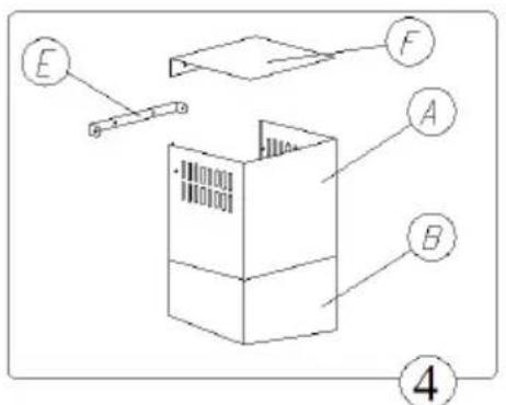
f) Hold the hanger of the top masking cover [E] at the center line, at a distance of 65 mm from the indicated point of max. reach (Fig. 4), indicate the mounting holes on the wall and install the hanger as described under d
g) Install the masking cover column again and, using appropriate screws, fix it to the bottom masking cover and the top hanger profile,
h) Connect the hood to the power supply network.
3. Connecting to the power network and operation check
After connecting the device to the power supply network (in accordance with the requirements defined above) it is necessary to check the lighting of the hood and whether its motor works correctly. The wall socket shall be accessible for disconnecting the plug after the hood is installed.
4. Setting the operation mode of the kitchen extractor hood
4.1 Setting the air extractor mode of operation of the hood
In the extractor mode air is discharged to the outside by a special conduit. In that setting any carbon filters shall be removed.
The hood can be connected to the opening discharging air to the outside by means of a rigid or flexible conduit of 150 or 120 mm diameter, and appropriate clamps for conduits which should be purchased in a shop selling installation materials.
A qualified installer should be commissioned to make the connection.
4.2 Setting the odour absorber mode of operation of the hood
In this option filtered air returns to the room through cut outs on both sides of the top funnel.
In this setting it is necessary to install the carbon filter; installation of the air exhaust guide is recommended.
4.3 Fan speeds
The lowest and medium speeds should be used under normal conditions and with low concentration of fumes. The top speed should be used in case of high concentration of kitchen fumes, e.g. during frying or grilling.
VI Operation and maintenance
1. Operational safety
All safety instructions included in this manual shall be observed without exception!
Grease filters and active carbon filters should be cleaned and replaced according to manufacturer's instructions, or more frequently in periods of intensive use (more than 4 hours a day).
If a gas cooker is used it is forbidden to leave uncovered flame. When removing pots from gas burners set the flame to its minimum level.
Always make sure that flame does not extend outside the pot. Such a situation causes undesired energy losses and dangerous heat build-ups.
The hood should not be used for other purposes than those for which it was designed.
2. Operation
2.1 Control panel
Operation of the hood can be controlled by means of a combined switch.
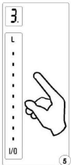
Sensor "Slider"- adjust the fan speed level, ranging from 1 to 9, Sensor "On / Off"(I / 0)
- turns on and off the fan
- turns on the fan, on last memorized fan speed,
- longer touch “on / off” sensor, when the fan is turned on, 5 min. timer is on (informing - a dot on the display).
Sensor "Light"(L)
- turns on / off lighting
- longer touch causes a gradual brightening / dimming of lighting, on 3 levels of 100, 75 and 50%
2.1 Program function
Timer function: DVG 8640 X kitchen extractor hood is equipped with the option of programming automatic switch-off of the hood fan after 5-minute. “Timer” is actuated by pressing „I/0” indicator during operation of the hood with the required fan speed. The display will flash and a dot will appear indicating that the device is in the switch-off time programming mode. After setting the delay pulsating dot will indicate that the time to switching off of the hood motor is being counted.
TIMER function can be cancelled by pressing “I/0” indicator again during counting of the time.
NOTE: The program always memorizes the last delay setting.
The microprocessor system may get deleted or crash during momentary voltage drops in the network, and stop responding to commands from the keyboard. In such case the hood has to be disconnected from and then connected again to the power network in order to reset the system.
3. Maintenance
Regular maintenance and cleaning of the device will guarantee its good and fault-less operation, and extend its life. Attention should be paid to replacing grease and carbon filters according to manufacturer's instructions.
3.1 Metal grease filters
1. Cleaning.
Grease filters should be cleaned every two months during normal operation of the hood, in a dishwasher or manually, using mild detergent or liquid soap.
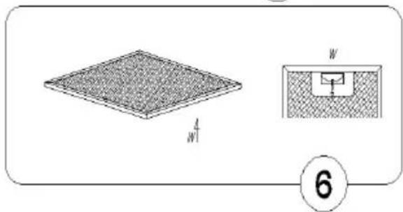
2. Replacement (Fig. 6).
To dismantle the filter proceed as follows:
a) remove the bottom cover by releasing the lock catch,
b) remove the metal grease filter
3.2. Carbon filter
1. Operation.
Carbon filters can be used only when the hood is not connected to any ventilation duct.
Filters with active carbon can absorb odours until they are saturated. They cannot be washed or regenerated and should be replaced at least every 2 months or more frequently in case of very intensive use.
2. Replacement.
a) Remove the metal grease filter,
b) Remove the carbon filter situated on the aluminium filter (Fig.6)
c) Install a new filter on the aluminium filter
3.3. Lighting
The lighting system consists of two halogen lamps.
To replace a light bulb proceed as follows:
a) Using a flat tool or screwdriver prise the ring holding the halogen lamp glass (Fig. 8) and, holding it, remove to the outside.
b) Replace the bulb using a piece of cloth or paper for that purpose.
c) Then reinstall the ring and the glass proceeding in reverse order.
Note: Make sure that you do not touch the halogen bulb to be installed with your bare fingers!
3.4. Cleaning
The following shall be avoided during normal cleaning of the hood:
- wet cloth or sponge and water jet,
- solvents or alcohols which might dull lacquered surfaces,
• caustic agents, particularly in regard to cleaning stainless steel elements, - hard, rough cloth
It is recommended to us moist cloth and neutral cleaning agents.
natural_image
Diagram showing a 3D grid structure with labeled dimensions and an inset basketball court view (no text or symbols)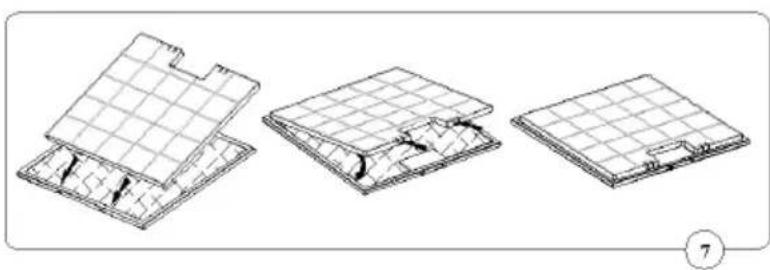
natural_image
Three technical line drawings of a grid-patterned architectural or structural component, shown from different angles (no text or symbols)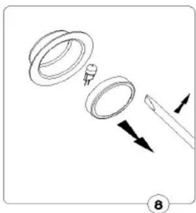
natural_image
Diagram showing three stages of a mechanical component with arrows indicating direction (no text or symbols)
natural_image
Abstract geometric logo with nested V-shaped and triangle shapes (no text or symbols)- I Characteristics
- II Components
- IV Operating conditions
- SAFETY PRECAUTION
- V Installation
- To install the hood proceed as follows:
- Installation of the hood
- Connecting to the power network and operation check
- Setting the operation mode of the kitchen extractor hood
- Setting the air extractor mode of operation of the hood
- Setting the odour absorber mode of operation of the hood
- Fan speeds
- VI Operation and maintenance
- Operational safety
- Operation
- Control panel
- Program function
- Maintenance
- Metal grease filters
- Cleaning.
- Replacement (Fig. 6).
- Carbon filter
- Operation.
- Replacement.
- Lighting
- Cleaning
Brand : GORENJE
Model : DVG8640X
Category : Range hood