C-650 Plus II - Printer Godex - Free user manual and instructions
Find the device manual for free C-650 Plus II Godex in PDF.

| Product Type | Barcode Label Printer |
| Print Method | Direct Thermal / Thermal Transfer |
| Print Resolution | 203 dpi (8 dots/mm) |
| Max Print Width | 104 mm (4.09 inches) |
| Max Print Speed | 6 ips (152 mm/s) |
| Dimensions (W x D x H) | 285 x 225 x 170 mm |
| Weight | 2.8 kg (6.17 lbs) |
| Power Supply | 100-240 VAC, 50/60 Hz |
| Interface | USB 2.0, Serial RS-232, Ethernet |
| Media Sensors | Gap sensor, Black mark sensor |
| Ribbon Capacity | 300 m (984 ft) max. length |
| Display | 2-line LCD with backlight |
| Supported Media Types | Labels, tags, receipts, fanfold, continuous |
| Supported Label Width | 25 mm to 118 mm |
| Label Length | 5 mm to 2540 mm (100 inches) |
| Cutting | Optional cutter module |
| Bar Code Symbologies | All major 1D and 2D codes |
| Operating Temperature | 5°C to 40°C (41°F to 104°F) |
| Storage Temperature | -20°C to 60°C (-4°F to 140°F) |
| Humidity | 20% to 85% (non-condensing) |
| Cleaning | Use a soft cloth with mild detergent; avoid abrasives |
| Maintenance | Periodic cleaning of print head and rollers |
| Safety | CE, FCC, UL approved |
| Spare Parts | Print head, platen roller, cutter blade (optional) |
| Repairability | Modular design for easy replacement of key parts |
Frequently Asked Questions - C-650 Plus II Godex
User questions about C-650 Plus II Godex
0 question about this device. Answer the ones you know or ask your own.
Ask a new question about this device
Download the instructions for your Printer in PDF format for free! Find your manual C-650 Plus II - Godex and take your electronic device back in hand. On this page are published all the documents necessary for the use of your device. C-650 Plus II by Godex.
USER MANUAL C-650 Plus II Godex
User Information according to European Directive 2002/95/EC and 2003/108/EC

natural_image
Symbol of a trash bin crossed with no text or labels, accompanied by a black rectangular block below (no readable text or symbols)This unit must be recycled or discarded according to applicable local and national regulations.
The symbol shown above, applied to the product or on its packing, indicates that, at end of life, the product is not to be thrown away, or disposed as unsorted municipal waste, but separately collected.
Godex encourages owners of information technology (IT) equipment to responsibly recycle their equipment when it is no longer needed.
Customer that needs to dispose this equipment must contact the produce and follow the collection framework available locally for the return, recycling and recovery of WEEE.
Customer participation to the separate collection is important to minimize any potential effects on the environment and human health, due to the potential presence of hazardous substances in the equipment, and aids the reuse and recycle of the materials by which the equipment is made.
Uncorrect disposal of the product by the customer will be punished according to the local regulations and Laws.
SPECIFICATIONS ARE SUBJECT TO CHANGE WITHOUT NOTICE.
This manual refers to various company and products by their trade names. In most of the cases, these designations are claimed as trademarks or registered tramarkers by their respective companies.
Copyright 2012 GODEX
Godex Product Information
Thanks for choosing the Godex FPB-650PII printer.
Your printer is a reliable working equipment that will be very useful in your daily job.
Our printers have been designed to be compact and respectful of the work environment. They offer a wide range of features and multiple functions that confirm the high technological level reached by Godex printers. To maintain these printing performances unchanged in the long run, Godex has developed its own specific branded consumables for each printer type that assure an excellent operation with high printing quality level reliability.
Godex recommends to use only its original Godex branded consumables with original packaging (identified by its holographic label). In this way, a proper use of the printer at quality level stated in the product characteristics can be assured. All typical usage problems related to not certified consumables may be avoided, such as an overall quality print level degradation and, often, the reduction of the product life due to the fact that the proper working conditions for the print heads and other printer parts are not assured.
Moreover, Godex does not only certify its consumables in terms of working conditions but also carefully controls their compliance with the international standard rules concerning:
no cancerous materials;
no flammability of the plastic materials;
other standards
Godex advises the customers not to use products for which the compliance to this safety rules are not warranted. Finally seek your dealer or contact a GODEX office and be sure that are provided you the original Godex branded consumables.
FCC Notes
This equipment has been tested and found to comply with the limits for a Class B digital device, pursuant to Part 15 of the FCC Rules. These limits are designed to provide reasonable protection against harmful interference when the equipment is operated in a commercial environment. This equipment generates, uses and can radiate radio frequency energy and, if not installed and used in accordance with the instruction manual, may cause harmful interference to radio communications. However, there is no guarantee that interference will not occur in a particular installation. If this equipment does cause harmful interference to radio or television reception, which can be determined by turning the equipment off and on, the user is encouraged to try to correct the interference by one or more of the following measures:
- Reorient or relocate the receiving antenna.
○ Increase the separation between the equipment and the receiver. - Connect the equipment into an outlet on a circuit different from that to which the receiver is connected
- Consult the dealer or an experienced technician for help.
A shielded Centronics IEEE1284 compliant bi-directional parallel cable, maximum length 3 meters (10 feet), and a shielded RS-232 serial cable, maximum length 15 meters (50 feet), are necessary for this device to meet the requirements of a Class B digital device pursuant to part 15 of the FCC rules.
The above specified cables are readily available as Personal Computer or Peripheral accessories from multiple retail outlets. Please consult your dealer for details concerning such cables and also for information about FCC rules for digital devices.
Changes or modifications to the device covered by this manual, which are not expressly approved by the party responsible for compliance, could void the user's authority under the FCC rules to operate the equipment.
Canadian D.O.C. Radio Interference Regulation
This digital apparatus complies with the Canadian ICES-003 Class B limits for radio frequency emissions.
This equipment conforms to the essential requirements of EU Directives 2006/95/EC, 2004/108/EC.
Per the applicable requirements of EU Directive 2006/42/EC (“machines”) sound pressure of this product (measured according to EN27779) does not exceed 70 dBA.
This product is also compliant to the EU directive 2002/95/EC (RoHS) and 2002/96/EC (WEEE).
Table of Contents
User Information according to European
Directive 2002/95/EC and 2003/108/EC i
Godex Product Information i Offset Adjustments 27
FCC Notes i Reading the Preprinted Setup Forms 28
Canadian D.O.C.
Radio Interference Regulation ii
EEC Regulations ii
Table of Contents iii
Printer Presentation 1
Unpacking the Printer 1
Printer Parts 2
Front View 2
Rear View 3
Inside View 3
Printer Installation 4
Installing the Power Cable 4
Installing the Ribbon Cartridge 5
Paper Handling 9
Loading Paper 9
The Operator Panel 10
Function Keys 10
Leds 11
LCD display messages 11
Software Driver Selection 12
Connection to the Host 13
Setting the Interface Parameters 14
Parallel Interface 14
Serial Interface 14
USB Interface 14
Printer Setup 15
Entering the Printer Setup Mode 15
Printing the Self Test Page 16
Printing the Printer Setup Forms 18
Filling the Printer Setup Forms 21
Setup Parameters 21
Printer Setup Flow Chart 29
Printer Setup through USB and RS232/C
Ports 30
Godex CDC RS-232 Emulation Driver
Installation 30
FBP-650PII Setup Utility Installation 32
Remote Setup 32
Read NVM 33
Troubleshooting 35
Paper Problems 35
Paper Jams 35
Paper Damaged after printing 36
Hexadecimal Dump 36
Error Handling 37
Recoverable Errors 37
Not-Recoverable Errors 38
Ribbon Cartridge Problems 39
Paper Specifications 40
Cut Sheets 40
Technical Specifications 41
Serial Interface Connection 42
Printer Presentation
This dot-matrix printer is a multi-purpose printer for front office applications. Its compact structure is designed for integration in an ergonomic environment. The printer provides a high level of reliability, form-handling accuracy and data integrity.
Its main features are:
○ Printing on a wide range of paper media: different types of cut sheets and multi-parts.
- High print pressure for multi-parts documents
o High print quality supplied by a 24 wire print head
o High reliability paper handling
The straight paper path allows the printing on particular documents such as envelopes and multipart forms.
○ Automatic paper thickness adjustment
The print head detects the paper thickness for correct printing on any type of document. This printer can print also on documents with a variable thickness.
- Easy paper handling
The operator places the paper on the front table and the printer loads it without any other user intervention. The paper ejection towards the front or the rear of the printer allows an easy access to the printed document.
○ Automatic document alignment feature
The printer checks automatically the alignment of the top margin of the document and adjusts it, if necessary. The printout is therefore performed correctly independently from the paper loading position.
o Standard parallel, serial and USB interface with automatic switch-over function.
- Easy printer setup through an optically managed menu.
- Supported emulations: Epson 570, IBM Proprinter XL24E, XL24E AGM, IBM 2390+, 4722, 9068 and Olivetti PR40+, PR2, 2845.
Unpacking the Printer
Together with the printer the following items are included in the shipment box:
Notify any damage to your supplier.
- Ribbon Cartridge
Power Cable - CD-ROM with printer documentation and drivers.
- Quick Reference Guide
○ USB Cable
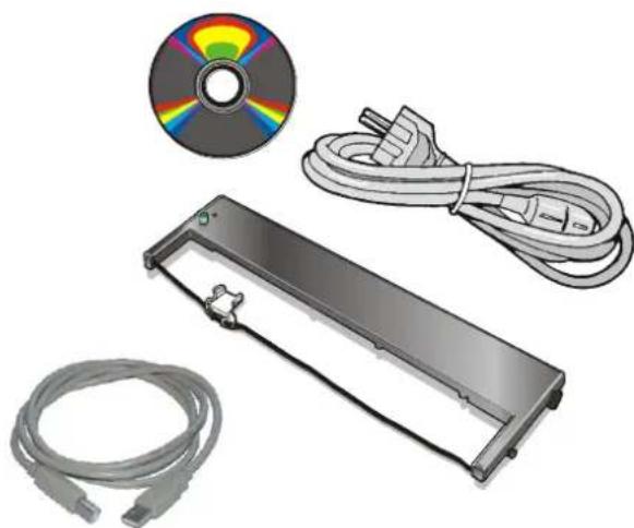
natural_image
Illustration of a CD or DVD device with two cables and a separate CD/DVD disc (no text or symbols)Always keep the packing material in a safe place as you must repack the printer into it, when you need to move it.
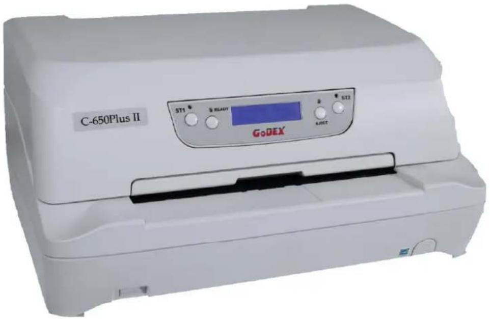
Printer Parts
Never remove any printer part unless it is expressly indicated in this manual.
Front View
Rear view
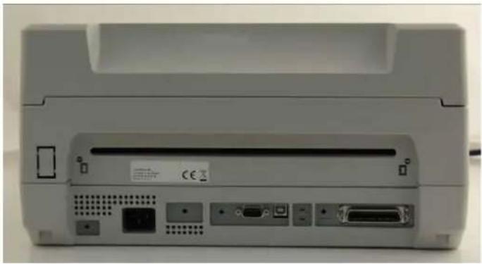
natural_image
Back view of a beige electronic device with ports and connectors (no visible text or symbols)Inside view
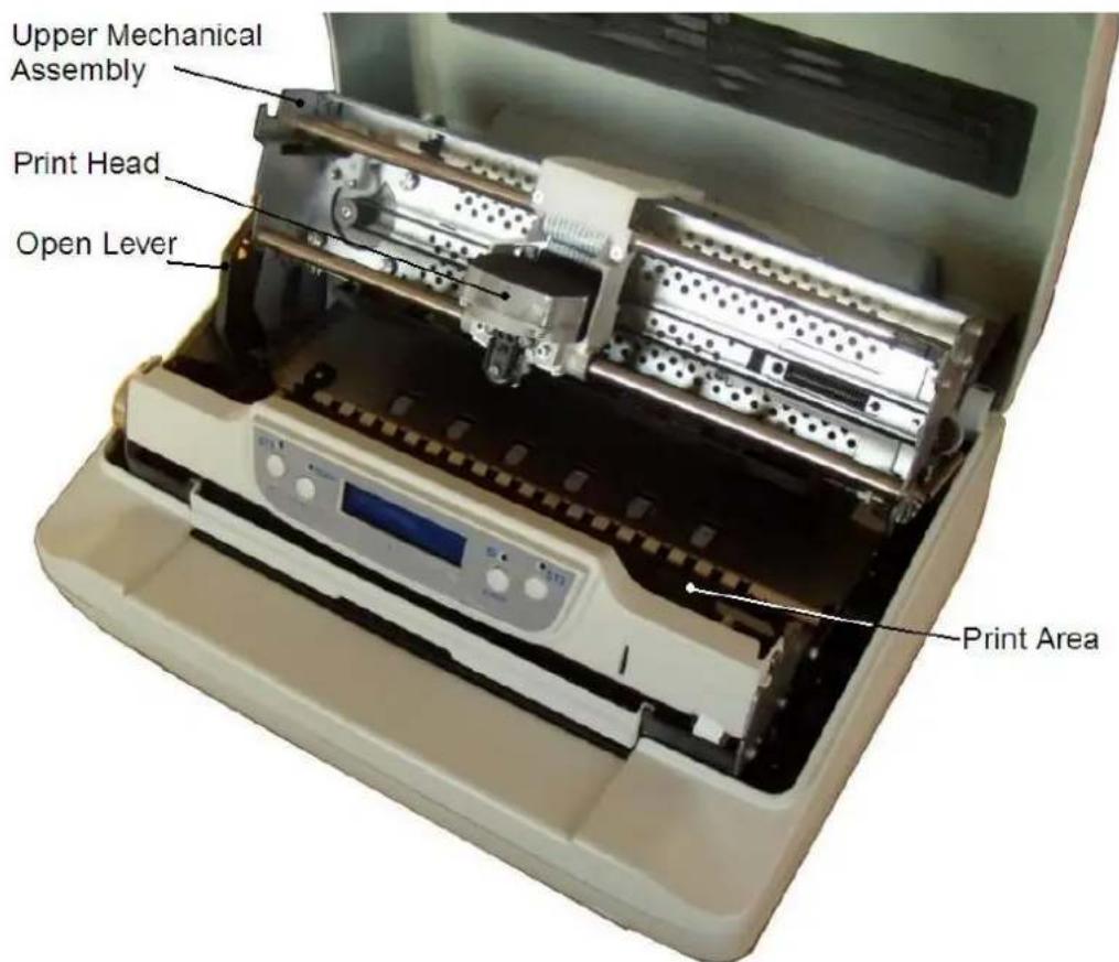
Inside View
Printer Installation
Choosing a Suitable Location
Consider the following points when you choose the location for your printer:
The distance between the printer and the host computer must not exceed the length of the interface cable; The location must be sturdy, horizontal and stable;
Your printer must not be exposed to direct sunlight, extreme heat, cold, dust or humidity;
When printing on standard paper formats, the paper comes out partially on the rear side of the printer. Make sure that behind the printer there is sufficient clearance to correctly move the paper.
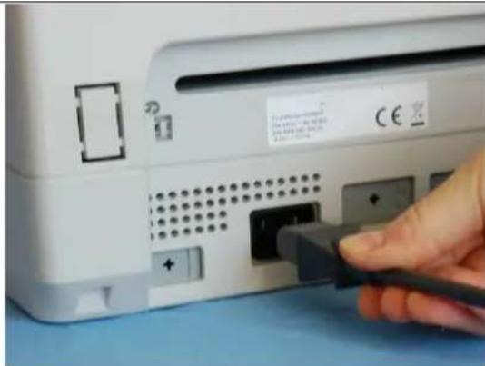
Installing the Power Cable
- Find the power cable connector on the rear side of the printer.
Always use a grounded outlet
- Insert the power cable into the connector on the printer and the other end into a convenient mains outlet.
natural_image
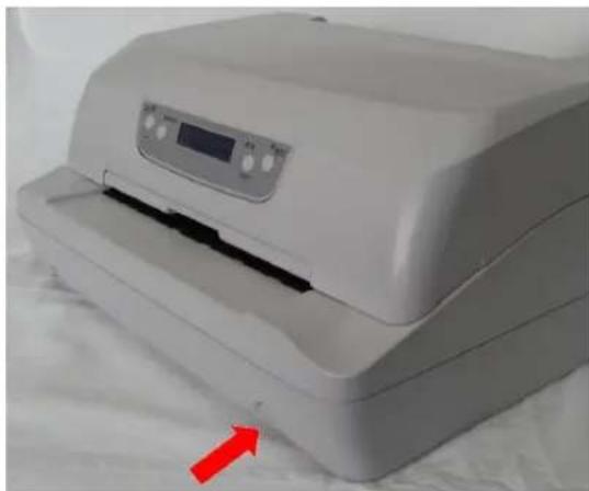
Close-up of a hand inserting a USB into a device panel (no visible text or symbols)- Press the key on the right side of the printer front to power the printer on.
natural_image
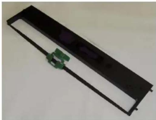
White printer with digital display and red arrow pointing to a textured surface (no visible text or symbols)Installing the Ribbon Cartridge
In order to avoid damaging the print head or mechanical gearings, this printer accepts only original Godex ribbon cartridges.
Therefore, if you install a not original cartridge, the printer may not work.
- Remove the cartridge from its bag.
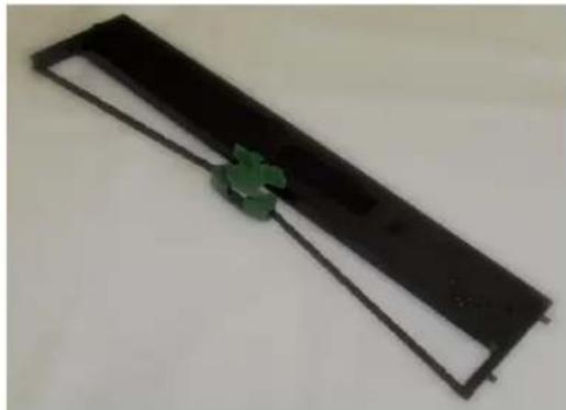
natural_image
Black rectangular object with a green flower-like symbol on its side, placed on a plain surface (no text or symbols visible)- Unhook the green ribbon mask from the cartridge pins.
natural_image
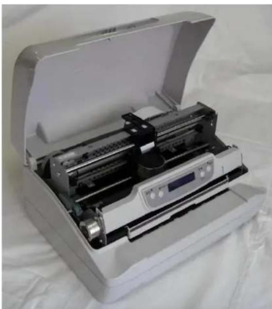
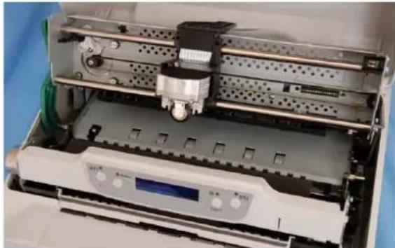
Black rectangular electronic component with a green connector, no visible text or symbols- Open the printer cover.
The print head will automatically move in the middle of the printer.
natural_image
Open industrial machine with internal components, no visible text or symbolsUser Manual
-
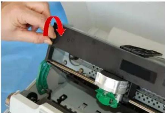
Open the upper mechanical frame. Locate the open green lever in the left side of the printer.
-
Unhook the green lever with the left hand towards the rear of the printer in the open position.
-
Then rise up the lever to its maximum position in order to completely open the head assembly.
-
Check for the "click" which means the correct open lever position, showed in the inset picture.

natural_image
Close-up of a green mechanical component being inserted into a white housing (no visible text or symbols)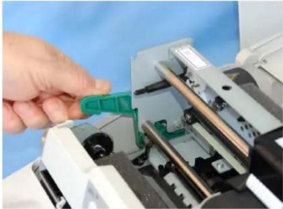
natural_image
Close-up of a hand inserting a green plastic clip into a printer or machine component (no visible text or symbols)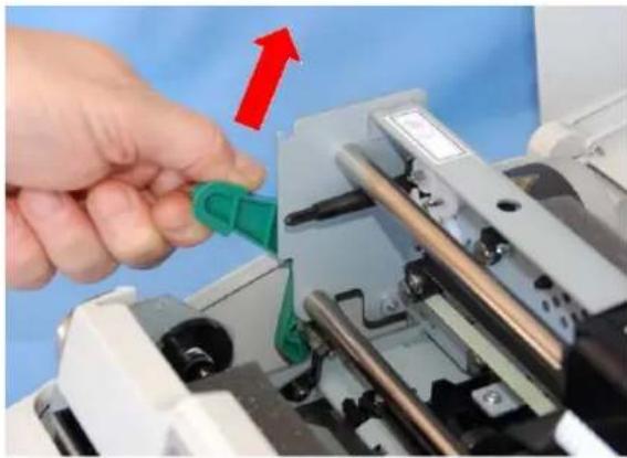
natural_image
Close-up of a hand inserting a green plastic clip into a mechanical device with a red upward arrow (no text or symbols visible)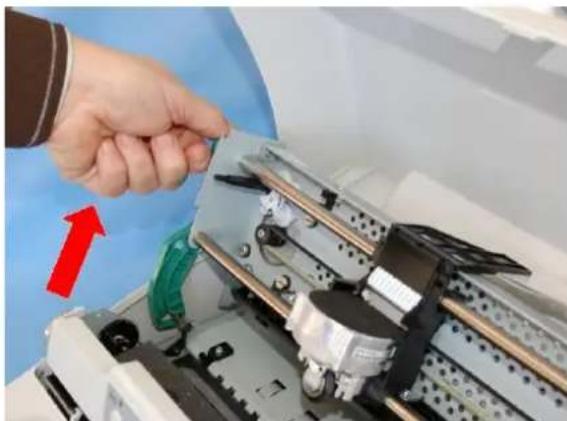
natural_image
Close-up of a hand inserting a component into a machine, with a red arrow indicating direction (no text or symbols visible)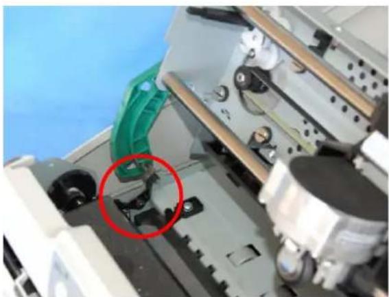
natural_image
Close-up of a mechanical assembly with a green handle and black components, no visible text or symbolsUser Manual
-
The printer is now ready to install the ribbon cartridge.
-
Turn the tension knob in the direction of the arrow to tighten the ribbon.
-
Insert the upper cartridge pins onto the corresponding grooves on both sides of the upper mechanical frame.
-
Then push the lower cartridge pins into the corresponding lower grooves on both sides of the upper mechanical frame until it clicks into place.
natural_image
Interior view of an industrial machine with a central component and control panel (no visible text or symbols)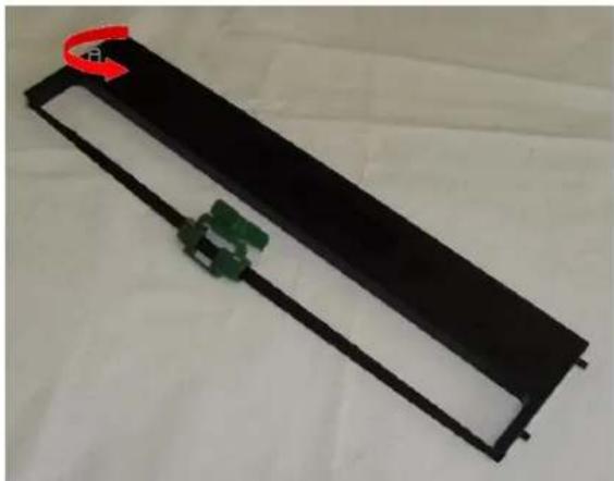
natural_image
Black rectangular electronic device with green connectors and a red circular component on top (no visible text or symbols)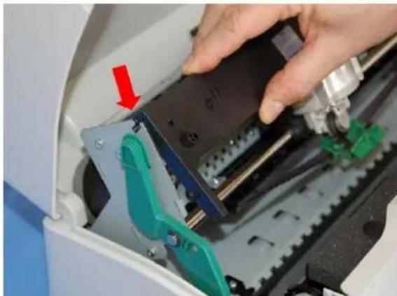
natural_image
Close-up of a hand operating a mechanical device with a red arrow pointing to a component (no visible text or symbols)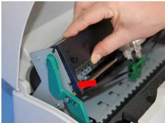
natural_image
Close-up of hands operating a mechanical device with green and red clamps, no visible text or symbolsUser Manual
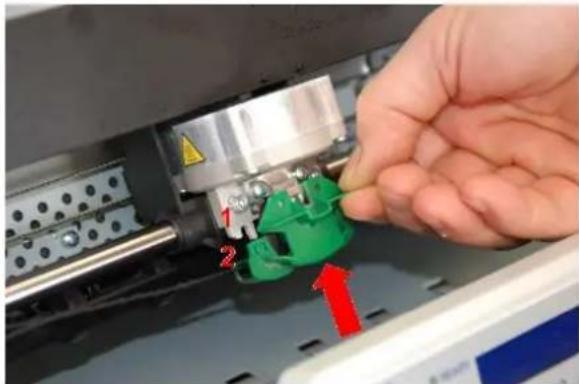
- Insert the green plastic ribbon mask onto the print head. Pay attention to match the two pins (2) on both sides of the green ribbon mask with the grooves (1) on both sides of the print head.
natural_image
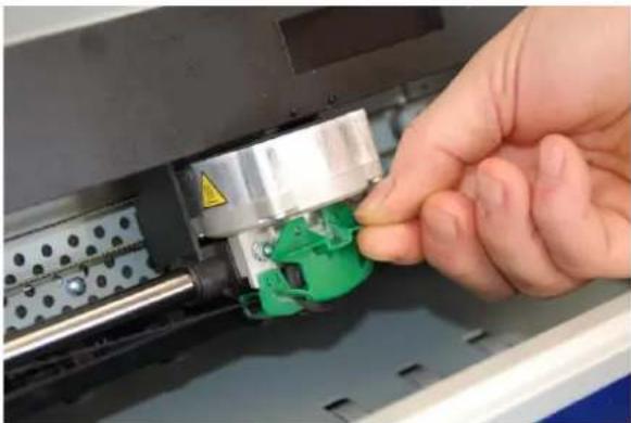
Close-up of a hand inserting a green plastic component into a machine, with red arrows indicating direction (no text or symbols visible)- Push the green ribbon mask up until it clicks into place.
natural_image
Close-up of a hand adjusting a green mechanical component on an industrial machine (no visible text or symbols)- Turn the tension knob in the direction of the arrow to tighten the ribbon
natural_image
Close-up of a hand inserting a red circular component into a device, with no visible text or symbols.-
Carefully pull down the green lever following the step 3, 4, and 5 in reverse order in order to securely close the Upper Mechanical Frame. If you do not LOCK the Upper Mechanical Frame, the printer does not print correctly.
-
Close the printer cover.
Remark
The printer detects the Ribbon Genuine type and the amount of printed characters and stops in error if appearing.
See "Error Message" later in this manual.
Paper Handling
This printer is designed for versatile and reliable paper handling. The flat-bed mechanism allows the handling of special documents, such as multiple invoices, postcards, labels and tickets.
The print head detects the paper edges automatically, the sheet can therefore be inserted in any position within the detection area according to the rules described in the following paragraph.
The paper alignment sensors determine the alignment of the upper paper margin, adjusting it if necessary.
Loading Paper
The inserted documents must not have folds, tears, pins, clips, staples or any foreign material.
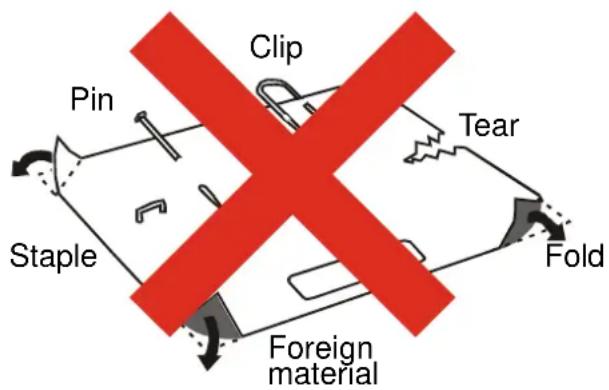
If you insert damaged documents or paper with foreign material, you can seriously damage the printer.
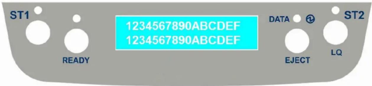
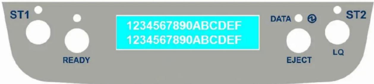
The Operator Panel
The operator panel is located in the middle of the printer cover and is composed of function keys and leds with which you can easily check the printer status and select the functions.
Function Keys
| KEY | NORMAL MODE | SETUP MODE | SPECIAL MODE |
 | When using the IBM 4722, IBM 9068 and the Olivetti protocols in two operators (“booking”) mode, the application software determines the function of this key. | When the Printer is in the Printer Setup mode, pressing this key the operator selects the Configuration Page to be printed. See “Printer Setup” later in this manual. | When pressed while powering the printer on with READY key selects the T&D mode (diagnostic).When pressed while powering the printer on with cover open enters in firmware upgrading procedure. |
 | Toggles the printer between Ready (on-line) and Local (off-line) status. | If pressed in the Printer Setup mode, the printer prints the Self Test Page.See “Printer Setup” later in this manual. | When pressed while powering the printer on, selects the Printer Setup Mode.When pressed while powering the printer on with ST1 key select the T&D mode (diagnostic). |
| EJECT | Pressing this key, when the printer is offline, or when the printer is online and no print data are in the buffer, the printer ejects the paper, if inserted (EJECT function). In the Olivetti protocols, the EJECT function may be performed only if the printer is offline. | ||
  | When using the IBM 4722, IBM 9068 and the Olivetti protocols in two operators (“booking”) mode, the application software determines the function of this key.When the printer is offline or when the printer is online and no print data are in the buffer, pressing this key, the printer toggles between Letter Quality and Draft printing mode (no Olivetti) | When the Printer is in the Printer Setup mode, pressing this key the Setup Page selected with the ST1 key will be printed. See “Printer Setup” later in this manual. | When pressed while powering the printer on, selects the HEX_DUMP mode.See “Hexdump Mode” later in this manual. |
Leds
| LED | NORMAL MODE | SETUP MODE | SPECIAL MODE |
 | Lit if paper presence, Unlit without paper (no Olivetti).When using the IBM 4722, IBM 9068 and the Olivetti protocols in two operators (“booking”) mode, the ST1 led is under software control. | If the printer is in Setup Mode, this led indicates which setup page is selected for printing. See “Printer Setup” later in this manual. | Blinks, together with the ST2 led, if a printer error occurs. See “ErrorMessage” later in this manual. |
 | Lit, when the printer is ready (on line).Unlit, when the printer is in local (off line). | If the printer is in Setup Mode, this led indicates which setup page is selected for printing. See “Printer Setup” later in this manual. | |
 | On, if the printer is powered on without data.Off, if the printer is powered off.Blinks if the printer has data traffic or data in the buffer. | Blinks if the printer is in Setup Mode. See “Printer Setup” later in this manual. | |
 | Lit when the Letter Quality print mode is selected. Unlit when the Draft printmode is selected.When using the IBM 4722, IBM 9068 and the Olivetti protocols in two operators (“booking”) mode, the S2 led is under software control. | If the printer is in Setup Mode, this led indicates which setup page is selected for printing. See “Printer Setup” later in this manual. | Blinks, together with the ST1 led, if a printer error occurs. See “ErrorMessage” later in this manual. |
LCD display messages
| Upper line messageLower line message | Indication |
| STARTING UP | The printer initialization phase is starting-up. |
| ..INIT.. | The printer initialization phase is ended |
| FPB-650PII Rel. xxx | The printer firmware release message |
| PRINTER READYPROG1 DRAFT | The printer is in normal ready status showing the current Program and the current Font |
| PRINTER READYHEX-DUMP MODE | The printer is in normal ready status in hex dump mode. |
| PRINTER OFF-LINEPUSH ON LINE | The printer is in off-line status. |
| PAUSE ON PRINTPUSH ON LINE | The printer is going in off-line status while data are in the buffer and ready to be printed. |
| WAITING MEDIAINSERT MEDIA | Data are sent to the printer, the printer is waiting for the insertion of the paper. |
| PRINTER BUSYEPSON PARALLEL | The printer is currently printing showing the used Emulation and interface |
| SET UP | The printer is in Set Up status and is waiting for a blank sheet to be loadedSee “Printer Setup” later in this manual. |
| SETUP PAG=CONFST1=PAG ST2=PRT | The printer is waiting for a Set Up operation selection.See “Printer Setup” later in this manual. |
| NVM CHANGED | The firmware of the printer has been updated and the NVM values have been resored to the default parameters. |
Software Driver Installation
At this point it is necessary to configure your printer for your application package.
The installation procedures depend upon the host environment.
The printer is Plug&Play, therefore when it is connected to a computer under Windows O.S., it automatically discovers the new hardware and it looks in the systems the proper drivers.
For this purpose, together with the printer you receive a CD-ROM containing the printer drivers for the Windows environment. This printer supports the Plug&Play facility in the 2000 / XP / Vista (32 or 64 bits) / Win 7 (32 or 64 bits).
If you want to install the printer in the Windows environment, insert the CD-ROM and follow the given instructions.
Connection to the Host
This printer can be connected to the host by means of the following available interface ports:
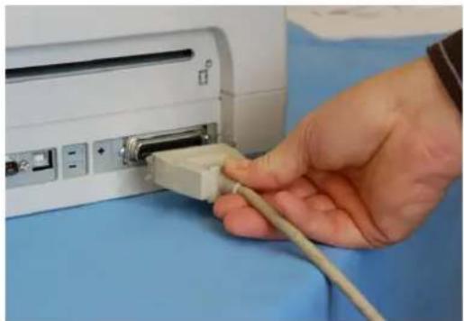
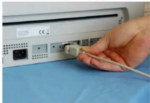
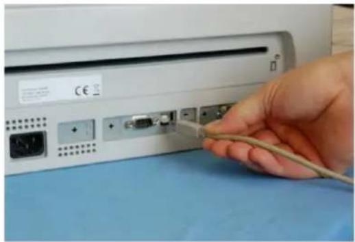
- Parallel standard Centronics or bi-directional IEEE 1284 type interface
- Serial RS-232/C interface
- USB 2.0 full speed interface
Proceed as follows:
Make sure that both the host and the printer are turned off.
Identify the connector for the interface you want to plug and firmly insert the cable into it.
Fix the cable by means of the corresponding hooks or screws. on either side of the connector.
natural_image
Close-up of a hand inserting a USB into a computer port (no visible text or symbols)Parallel Interface Connection
natural_image
Hand inserting a cable into a device port, showing ports and connectors (no text or symbols visible)Serial Interface Connection
natural_image
Hand inserting a cable into a computer monitor (no visible text or symbols)USB Interface Connection
Setting the Interface Parameters
Parallel Interface
The parameters set for the parallel interface mainly match of the most common environments and the printer can be used immediately after connection to the host.
In case you need to modify the standard parameters see "Printer Setup" later in this section.
Serial Interface
Because of the great variety of the possible connection configurations, when you use the serial interface you will need to set the parameters accordingly.
To assure a correct functioning of the printer connected through the serial interface, the transmission parameters set for the printer must match the values set for the host.
In case you need to modify the standard parameters see "Printer Setup" later in this section.
USB Interface
Once the Godex FPB-650PII driver has been correctly installed, printer can be immediately used with USB port.
For a complete description of the printer setup procedure see the paragraph "Printer Setup" later in this manual.
Printer Setup
The Printer Setup is used to configure the printer parameters and to print a Self Test page, to check the settings and the printer installation, and to perform the Print Offset Tuning.
The default configuration of this printer matches most of the commonly used environments, but it may be necessary to change some printer parameters.
With this printer you print the forms for the setup, you fill them in, and then you insert them back into the printer for reading.
Once the printer reads the form, the new values are set.
The following is the complete description of the Setup Procedure.
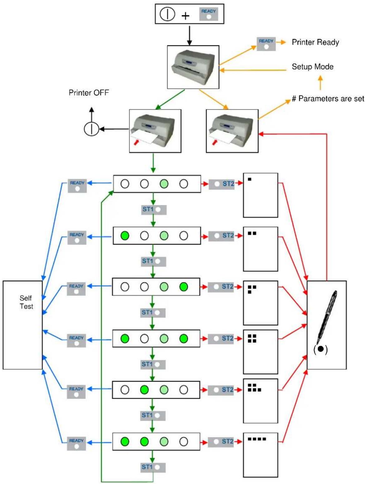
Entering the Printer Setup Mode
To enter the Printer Setup Mode press and hold the READY key pressed for at least 1 second while powering the printer on. The printer enters the Setup Mode.
The leds ST1, ST2 and READY are unlit, the DATA led is flashing.
You can now:
Print the Self Test. See "Printing the Self Test" later in this manual.
Print one of the Printer Setup Forms (Configuration Menu or Program1 – Program2 – Program 3 - Program4 Menu) or the Offset Tuning Form. See “Printing the Printer Setup Forms” later in this manual.
Insert a filled-in Printer Setup Form to set the corresponding Setup values.
Printing the Test Page
The Self Test page is useful to test, if the printer has been correctly installed, and allows to see the current parameter settings.
- With the printer in the Setup Mode, insert a single sheet in A4 or Letter format.
- The printer loads the sheet and stops.
- Press the READY key again.
The printer prints the Self-Test page. Check that the printout is correct. The following printout example shows the Printer Setup default values.
Once the self-test is finished, the printer remains in Setup Mode.
SELF TEST
C650PlusII : Code Version v1.33 CharGen : 78411902 ver.4.07 (Godex Europe GmbH - Arazhausen 36, 42929 Wermelskirchen) SERIAL NUMBER : 00000000
CONFIGURATION SETUP
| DISPLAY LANG. | English | BUFFER CONTROL | DTR+SRTS |
| PROGRAM | on interface | ROBUST XON | enabled |
| ERROR BUZZER | enabled | WORD LENGTH | 8 bit |
| JOB BUZZER | no beep | BAUD RATE | 9600 bps |
| COPIES | no | PARITY BIT | none |
| LOW NOISE | no | STOP BIT | 1 |
| SAFE BOTTOM EDGE | yes | USB MODE | 2.0 |
| GET EDGE QUOTE | 1/4" | ||
| PASSBOOK TYPE | sw controlfixed thick | ||
| INTERFACE TYPE | automatic | ||
| IBM FINANCIAL | no | ||
| INPUT BUFFER | 8 Kb | ||
| AUTOFEED SIGNAL | disabled | ||
| SLCT-IN SIGNAL | disabled | ||
| IGNORE PE | enabled | ||
| RIBBON LIFE (3f) | 12K chars | PRINT HEAD LIFE | 67K chars |
PROGRAM SETUP
| PROGRAM 1 | PROGRAM 2 | PROGRAM 3 | PROGRAM 4 | |
| PROTOCOL | EPSON 570 | OLI. PR2 | IBM X24E | OLI. PR2 |
| FONT | Draft | Draft | Draft | Draft |
| QUALITY MODE | 1q | 1q | 1q | 1q |
| DRAFT MODE | draft | draft | draft | draft |
| DOWNLINE LOADING | enabled | enabled | enabled | enabled |
| HORIZONTAL PITCH | 10 cpi | 10 cpi | 10 cpi | 10 cpi |
| VERTICAL PITCH | 6 lpi | 6 lpi | 6 lpi | 6 lpi |
| LOCK | no lock | no lock | no lock | no lock |
| FORM LENGTH | A4 | A4 | A4 | A4 |
| 70 | 70 | 70 | 70 | |
| LEFT MARGIN | 0 | 0 | 0 | 0 |
| RIGHT MARGIN | 93 | 93 | 93 | 93 |
| TOP MARGIN | 0 | 0 | 0 | 0 |
| BOTTOM MARGIN | 0 | 0 | 0 | 0 |
| IBM C-SET | IBM set 1 | IBM set 1 | IBM set 1 | IBM set 1 |
| IBM COMPRESS | 17.1 cpi | 17.1 cpi | 17.1 cpi | 17.1 cpi |
| EPSON C-SET | graphic | graphic | graphic | graphic |
| NATION C-SET | USA | USA | USA | USA |
| CODE PAGE | CP437 | CP437 | CP437 | CP437 |
| OLIVETTI C-SET | INTERN. | INTERN. | INTERN. | INTERN. |
| OLIVETTI COMPRES | 17.1 cpi | 17.1 cpi | 17.1 cpi | 17.1 cpi |
| VERT. RESOLUTION | 1/240 inch | 1/240 inch | 1/240 inch | 1/240 inch |
| PRINT DIRECTION | sw control | sw control | sw control | sw control |
| LINE MODE | LF=LF,CR=CR | LF=LF,CR=CR | LF=LF,CR=CR | LF=LF,CR=CR |
| WRAP MODE | autowrap | autowrap | autowrap | autowrap |
| REFERENCE EDGE | left | left | left | left |
| SLASHED ZERO | no | no | no | no |
| EJECT ON FF | yes | yes | yes | yes |
| RESET WITH EJECT | yes | yes | yes | yes |
| CUT SHEET EJECT | on front | on front | on front | on front |
| VERT.POS 1/10" | 0 | 0 | 0 | 0 |
| VERT.ADJ 1/60" | 0 | 0 | 0 | 0 |
| HORIZ.POS 1/10" | 0 | 0 | 0 | 0 |
| HORIZ.ADJ 1/60" | 0 | 0 | 0 | 0 |
Printing the Printer Setup Forms
If you already have the preprinted forms for the printer setup, go to "Filling in the Printer Setup Forms" later in this manual.
- With the printer in Setup Mode, insert a blank sheet in A4 or Letter format.
- The printer loads the sheet and stops.
- If you press the ST1 key, the three leds change and you can select the Setup Page you want to print as follows:
$$ ⓞ = \text { unlit } = ⓕ = \text { flashing } $$
Pressing the ST2 key, the printer prints the selected Setup Page, showed in next pages.
Only the Program 1 Setup Page printout is reported because the other are exactly the same except for the marker.
The printer setup forms contain all printer parameters and the values that can be set. The current value is indicated by an asterisk (*).
For a detailed description of the parameters and the settings see "Setup Parameters" later in this manual.
Each Setup form is identified by a marker in the upper left corner of the page as follows:
| Configuration Setup | ( ) FPB-650PII | |
 | Program 1 | ( ) FPB-650PII |
 | Program 2 | ( ) FPB-650PII |
| [YW8Z] | Program 3 | ( ) FPB-650PII |
| [WHZZ] | Program 4 | ( ) FPB-650PII |
| [XBBV] | Offset Tuning Setup | ( ) FPB-650PII |
In this line an empty marker ( ) is printed within the printer model and the Code Version to be used for the white calibration check.
Remark: do not fill this empty marker
For the printer with operator panel with LCD, the SETUP operation are directly displayed on the LCD jointly with the above described leds combination.
| CONFIGURATION SETUP ( )C650PlusII : Code Version v1.33 | ||||||||
| RESTORE TO MFG | ( )no* | ( )all | ( )config | ( )prog.1 | ( )prog.2 | ( )prog.3 | ( )prog.4 | |
| DISPLAY LANG. | ( )English* | ( )Italian | ( )German | ( )French | ( )Spanish | ( )Czech | ||
| PROGRAM | ( )progr.1 | ( )progr.2 | ( )progr.3 | ( )progr.4 | ( )on interface* | |||
| ERROR BUZZER | ( )disabled | ( )enabled* | ||||||
| JOB BUZZER | ( )no beep* | ( )1 beep | ( )continuous | |||||
| INTERFACE TYPE | ( )parallel | ( )serial | ( )serial_2 | ( )usb | ( )automatic* | |||
| IBM FINANCIAL | ( )no* | ( )honorCTS | ( )ignoreCTS | |||||
| INPUT BUFFER | ( )1 Kb | ( )8 Kb* | ( )16 Kb | ( )32 Kb | ( )64 Kb | ( )128 Kb | ||
| IGNORE PE | ( )disabled | ( )enabled* | ||||||
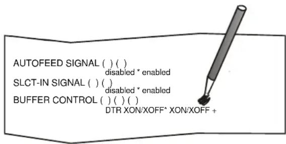
| AUTOFEED SIGNAL | ( )disabled* | ( )enabled | ||||||
| SLCT-IN SIGNAL | ( )disabled* | ( )enabled | ||||||
| BUFFER CONTROL | ( )DTR+SRTS* | ( )SRTS | ( )XON/XOFF | ( )ETX/ACK | ( )XON/XOFF+DTR+SRTS | |||
| ROBUST XON | ( )disabled | ( )enabled* | ||||||
| WORD LENGTH | ( )7 bit | ( )8 bit* | ||||||
| BAUD RATE | ( )1200 bps | ( )2400 bps | ( )4800 bps | ( )9600 bps* | ( )19200 bps | ( )38400 bps | ||
| PARITY BIT | ( )even | ( )odd | ( )space | ( )mark | ( )none* | |||
| STOP BIT | ( )1* | ( )2 | ||||||
| USB MODE | ( )2.0* | ( )1.1 | ||||||
| COPIES | ( )no* | ( )yes | ||||||
| LOW NOISE | ( )no* | ( )yes | ||||||
| SAFE BOTTOM EDGE | ( )no | ( )yes* | ||||||
| GET EDGE QUOTE | ( )0/4" | ( )1/4"* | ( )2/4" | ( )3/4" | ( )4/4" | ( )5/4" | ( )6/4" | ( )7/4" |
| PASSBOOK TYPE | ( )setup | ( )sw control* | ||||||
| ( )fixed thick*( )vertical | ( )horizontal | |||||||
| PROGRAM 1 | ( )C650PlusII : Code Version v1.33 | ||||||||||
| PROTOCOL | ( )EPSON S70* | ( )IBM X24E | ( )X24E AGN | ( )IBM 2390 | ( )OLI. PR40* | ( )OLI. PR2 | ( )OLI. PR2845 | ( )IBM 4722 | |||
| ( )IBM 9068 | ( )HPR 4915 | ||||||||||
| FONT | ( )Draft* | ( )Courier | ( )OCR-B | ( )Gothic | ( )Prestige | ( )Present | ( )OCR-A | ( )Script | |||
| ( )Boldface | |||||||||||
| QUALITY MODE | ( )lq* | ( )nlq | DRAFT MODE | ( )draft* | ( )hsd | ( )vhsd | |||||
| DOWNLINE LOADING | ( )disabled | ( )enabled* | |||||||||
| HORIZONTAL PITCH | ( )10 cpi* | ( )12 cpi | ( )15 cpi | ( )16.6 cpi | ( )17.1 cpi | ( )20 cpi | |||||
| VERTICAL PITCH | ( )5 lpi | ( )6 lpi* | ( )8 lpi | ||||||||
| LOCK | ( )no lock* | ( )font | ( )hor .pitch | ( )font + hor .pitch | |||||||
| FORM LENGTH | ( )lines | ( )M* | ( )letter | ( )A5 | ( )legal | ||||||
| 100 x ( )0 | ( )1 ( )2 | ||||||||||
| 10 x ( )0 | ( )1 ( )2 | ( )3 ( )4 | ( )5 ( )6 | ( )7 ( )8 | ( )9 | Minimum = 1 | |||||
| 1 x ( )0 | ( )1 ( )2 | ( )3 ( )4 | ( )5 ( )6 | ( )7 ( )8 | ( )9 | Maximum = 255 | Current = 70 | ||||
| LEFT MARGIN | 10 x ( )0 | ( )1 ( )2 | ( )3 ( )4 | ( )5 ( )6 | ( )7 ( )8 | ( )9 | Minimum = 0 | ||||
| 1 x ( )0 | ( )1 ( )2 | ( )3 ( )4 | ( )5 ( )6 | ( )7 ( )8 | ( )9 | Maximum = 90 | Current = 0 | ||||
| RIGHT MARGIN | 100 x ( )0 | ( )1 | |||||||||
| 10 x ( )0 | ( )1 ( )2 | ( )3 ( )4 | ( )5 ( )6 | ( )7 ( )8 | ( )9 | Minimum = 0 | |||||
| 1 x ( )0 | ( )1 ( )2 | ( )3 ( )4 | ( )5 ( )6 | ( )7 ( )8 | ( )9 | Maximum = 190 | Current = 93 | ||||
| TOP MARGIN | 10 x ( )0 | ( )1 ( )2 | ( )3 ( )4 | ( )5 ( )6 | ( )7 ( )8 | ( )9 | Minimum = 0 | ||||
| 1 x ( )0 | ( )1 ( )2 | ( )3 ( )4 | ( )5 ( )6 | ( )7 ( )8 | ( )9 | Maximum = 90 | Current=0 | ||||
| BOTTOM MARGIN | 10 x ( )0 | ( )1 ( )2 | ( )3 ( )4 | ( )5 ( )6 | ( )7 ( )8 | ( )9 | Minimum = 0 | ||||
| 1 x ( )0 | ( )1 ( )2 | ( )3 ( )4 | ( )5 ( )6 | ( )7 ( )8 | ( )9 | Maximum = 90 | Current = 0 | ||||
| IBM C-SET | ( )IBM set 1* | ( )IBM set 2 | IBM COMPRESS | ( )17.1 cpi* | ( )20 cpi | ||||||
| EPSON C-SET | ( )italic | ( )graphic* | |||||||||
| NATION C-SET | ( )USA* | ( )FRANCE | ( )GERMANY | ( )ENGLAND | ( )DENMARK1 | ( )SHEDEN | ( )ITALY | ( )SPAIN1 | |||
| ( )JAPAN | ( )MORWAY | ( )DENMARK2 | ( )SPAIN2 | ( )LATIN A1 | |||||||
| CODE PAGE | ( )CP437* | ( )CP437G | ( )96GREEK | ( )CP850 | ( )CP851 | ( )CP852 | ( )CP853 | ( )CP855 | |||
| ( )CP857 | ( )CP858 | ( )CP860 | ( )CP862 | ( )CP863 | ( )CP864 | ( )CP865 | ( )CP866 | ||||
| ( )CP867 | ( )CP876 | ( )CP877 | ( )CP1098 | ( )CP1250 | ( )CP1251 | ( )CP1252 | ( )CP1257 | ||||
| ( )POST | ( )TASS | ( )HAZOWIA | ( )CP437SL | ( )UKRAIN | ( )X018-U | ( )8859/1 | ( )8859/2 | ||||
| ( )8859/3 | ( )8859/4 | ( )8859/5 | ( )8859/6 | ( )8859/7 | ( )8859/8 | ( )8859/9 | ( )8859/15 | ||||
| ( )ROMAN-8 | ( )ID 12 | ( )CP874 | ( )ID 14 | ( )ID 17 | ( )SANYO | ( )KU | ( )PHILIP | ||||
| OLIVETTI C-SET | ( )CODE PAGE | ( )INTERN.* | ( )GERMANY | ( )PORTUGAL | ( )SPAIN 1 | ( )DEN/NORM | ( )FRANCE | ( )ITALY | |||
| ( )SWE/FIN | ( )SWISS | ( )6 . BRITAIN | ( )USA ASCII | ( )GREECE | ( )ISRAEL | ( )SPAIN 2 | ( )JUGOSLAVIA | ||||
| ( )TCV 370 | ( )CANADA | ( )SDC | ( )TURKEY | ( )ARABIC | ( )CIBC | ( )PC-DEN/NORM | ( )PC-DEN OPE | ||||
| ( )PC-210 | ( )PC-220 | ( )OLI-UNIX | |||||||||
| OLIVETTI COMPRES | ( )17.1 cpi* | ( )16.6 cpi | VERT. RESOLUTION | ( )1/216 inch | ( )1/240 inch* | ||||||
| CUT SHEET EJECT | ( )on front* | ( )on rear | PRINT DIRECTION | ( )unidir. | ( )bidir. | ( )su control* | |||||
| LINE MODE | ( )LF=LF,CR=CR* | ( )CR=LF+CR | ( )LF=LF+CR | ( )LF&CR=LF+CR | |||||||
| WRAP MODE | ( )truncate | ( )autowrap* | REFERENCE EDGE | ( )left* | ( )right | ||||||
| SLASHED ZERO | ( )no* | ( )yes | EJECT ON FF | ( )no | ( )yes* | ||||||
| RESET WITH EJECT | ( )no | ( )yes* | |||||||||
Filling in the Printer Setup Forms
To change the values of the parameters, fill in the marker ( ) beside the value you want to set with a black or blue ball-point pen or a fiber-pen.
Do not use pencils.
If more than one value is set for a parameter, the printer ignores these parameters and maintains the currently set value.
Do not fill in the marker beside the title of the preprinted form, otherwise the printer will not be able to read that page.
For a detailed description of the parameters and values contained in the Configuration and Program1, Program2, Program3 and Program4 Menus, see "Setup Parameters" later in this manual.
For a detailed description of the Offset Tuning procedure, see "Offset Adjustment" later in this manual.
Setup Parameters
The following is a listing of the setup parameters.
Configuration Setup ( ) FBP-650PII : Code Version xxxx
| Setup Parameter | Values | Description |
| RESTORE TO MFG | No*allconfigprog. 1, prog. 2prog. 3, prog. 4 | The selected values are not set to factory defaults.The values set in all printer setups are reset to factory defaults.The values set in the configuration setup are reset to factory default values |
| PROGRAM | prog. 1, prog. 2prog. 3, prog. 4on interface(*) | Defines the default Program Setup. Selecting prog.1, prog. 2, progr 3 or progr.4 the setup parameters set in the corresponding Program Setup are set. Selecting on interface the printer matches the Program 1 settings with the data arriving on the Centronics interface, the Program 2 settings with the data it receives from the serial interface, Program 3 settings with the data from USB interface and Program 4 setting fo any other optional interface.When changing from one interface to the other, the default values are set for the corresponding Program Setup. |
| ERROR BUZZER | Disable, enable* | Enables or disables the buzzer in case of an error. |
| JOB BUZZER | no beep*,1 beep, continuous | Selects the behavior of the buzzer when a new print job starts: no signal (no beep), one beep (1 beep) or a continuous signal (continuous). |
| INTERFACE TYPE | parallel, serial, opt, usb, automatic* | Selects the interface type. In case of printer with optional interface ports are installed, they are listed to be selected. Choosing ‘automatic’ the interface type is selected between all the available interface ports depending on data coming from host. |
| IBM FINANCIAL | No* | Disables the Financial protocol if IBM 4722 or IBM 9068 emulation is selected |
| honorCTS, ignoreCTS | Enables the IBM FINANCIAL for the IBM 4722 and 9068 protocols. Considers (handles) or ignores the CTS signal received from host for the control of the data stream from host | |
| INPUT BUFFER | 1 Kb, 8 Kb*, 16 Kb, 32 Kb, 64 Kb | Selects the buffer size.When the 'financial' interface is selected, this setting is ignored. |
| IGNORE PE | Enabled, disable* | Selects whether the printer signals the paper empty condition (disabled) or not (enabled) on the busy line. |
| AUTOFEED SIGNAL | Disable*, enabled | The parallel interface uses (enabled) or does not use (disabled) the AUTOFEED signal. |
| SLCT-IN SIGNAL | Disable*, enabled | The parallel interface uses (enabled) or does not use (disabled) the SELECT-IN signal. |
| BUFFER CONTROL | DTR+SRTS*, SRTS, XON/XOFF, ETX/ACK, XON/XOFF+DTR+SRTS | Selection of the buffer protocol. When the 'financial' interface is selected, this setting is ignored. |
| ROBUST XON | Enabled*, disabled | Perform the Robust XON (enabled) or not (disabled). |
| WORD LENGTH | 7 bit, 8 bit* | Sets the number of the data bits. When the 'financial' interface is selected, this value is always set to 8 bits. |
| BAUD RATE | 1200, 2400, 4800, 9600*, 19200, 38400 bps | Sets the data transfer rate. |
| PARITY BIT | even, odd, space, mark, none* | Selects the parity control for the data. |
| STOP BIT | 1*,2 | Selects the number of stop bit. |
| USB MODE | 2.0*, 1.1 | Select the USB specification level |
| COPIES | no, yes* | Selects the printing on normal paper (no) or on multicopy format paper (yes) |
| LOW NOISE | No*, yes | Disables/enables the low noise function |
| SAFE BOTTOM EDGE | no, yes* | Distance from the bottom of the last printer line. Yes = 5,8 mm from bottom edge no = 1,5 mm from bottom edge |
| GET EDGE QUOTE | 0/4", 1/4"*, 2/4", 3/4", 4/4", 5/4", 6/4", 7/4 | Sets the position in which the left paper edge is checked. If set to 0, the check is performed at the first line. The other values correspond to the physical distance from the first line. |
| PASSBOOK TYPE | Setup sw control* | Enables the setting made in the current PASSBOOK TYPE section and the specific Escape command is not actives. Enables the specific ESCape command. Printing a document with fixed thickness. Printing of passbooks with vertical binding. Printing of passbooks with horizontal binding |
| Fixed thick* | ||
| Vertical | ||
| Horizontal | ||
| PROTOCOL | EPSON 570*, IBM X24E*X24E AGM, IBM 2390,OLI. PR40+, OLI. PR2*,OLI. PR2845, IBM 4722, IBM9068, HPR 4915 | Defines the printer protocol.NOTE: For the IBM 4722 and 9068 protocols, ifthe software driver uses the controlled link ofthe IBM financial driver, set the IBM FINANCIALitem in the Configuration Menu.The default value is EPSON 570 for Program1,IBM X24E for Program 3, OLI. Pr2 for Program2 and 4. |
| FONT | Draft*, Courier, OCR-B,Gothic, Prestige, Present,OCR-A, Script, Boldface | Selects the font. |
| QUALITY MODE | LQ*, NLQ | Select the level of quality font. |
| DRAFT MODE | DRAFT*, HSD, VHSD | Select the level of draft font. |
| DOWNLINE LOADING | disabled, enabled* | Disable or enable the font downloading |
| HORIZONTAL PITCH | 10 cpi*, 12 cpi, 15 cpi,16.6 cpi, 17.1 cpi, 20 cpi | Selects the character spacing in characters perinch (cpi). |
| VERTICAL PITCH | 5 lpi, 6 lpi*, 8 lpi | Selects the line spacing in lines per inch (lpi). |
| LOCK | no lock*, font, hor. pitch,font+hor.pitch | The following selections made in the printer setupmay be locked: font, horizontal pitch (hor.pitch), oboth the font and horizontal pitch (font+hor. pitch)The locked settings cannot be changed viasoftware commands. |
| FORM LENGTH | # lines, A4*, letter, A5, legal | Sets the page length in number of lines orstandard formats A4, Letter, A5 or Legal. If youselect # lines, you must indicate the number oflines you want to set in the scheme below thisselection. The values range between 0 and 255.To set the values combine the numbersconsidering that the first line corresponds to thehundreds, the second line to the tens and the thiroline to the units. See the example below. |
Example:
How to set the form length to 82 lines:
FORM LENGTH
| #lines | ( )A4 | ( )Letter | ( )A5 | ( )Legal | ||||||
| 100x | ( )0 | ( )1 | ( )2 | |||||||
| 10x | ( )0 | ( )1 | ( )2 | ( )3 | ( )4 | ( )5 | ( )6 | ( )7 | ■8 | ( )9 |
| 1x | ( )0 | ( )1 | ■2 | ( )3 | ( )4 | ( )5 | ( )6 | ( )7 | ( )8 | ( )9 |
| Setup Parameter | Values | Description |
| LEFT MARGIN | 10 x | Sets the left margin in number of columns. The values range between 0 and 90. To set the values combine the numbers considering that the first line corresponds to the tens, the second line to the units. See the example below. |
| 1 x |
Example:
How to set the Left Margin to 20.
LEFT MARGIN
| Setup Parameter | Values | Description |
| RIGHT MARGIN | 100 x | Sets the right margin in number of columns. The values range between 0 and 190. The physical position of margin depends on the current character spacing. To set the values combine the numbers considering that the first line corresponds to the hundreds, the second line to the tens and the third line to the units. See the example below: |
| 10 x | ||
| 1 x |
Example:
How to set the Right Margin to 101.
RIGHT MARGIN
| Setup Parameter | Values | Description |
| TOP MARGIN | 10 x | Sets the top margin in number of lines. The values range between 0 and 90. To set the values combine the numbers considering that the first line corresponds to the tens, the second line to the units. See the example below. |
| 1 x |
Example:
How to set the Top Margin to 15.
TOP MARGIN
| Setup Parameter | Values | Description |
| BOTTOM MARGIN | 10 x | Sets the bottom margin in number of lines. The values range between 0 and 90. To set the values combine the numbers considering that the first line corresponds to the tens, the second line to the units. See the example below. |
| 1 x |
Example:
How to set the bottom margin to 34 lines:
BOTTOM MARGIN
| Setup Parameter | Values | Description |
| IBM C-SET | IBM set 1*, IBM set 2 | Selects the IBM character set. |
| IBM COMPRESS | 17.1 cpi*, 20 cpi | Selects the pitch for the compressed mode printing in IBM emulation. |
| EPSON C-SET | Italic, graphic* | Selects italic or graphic Epson character set. |
| NATION C-SET | USA*, FRANCE, GERMANY, ENGLAND, DENMARK1, SWEDEN, ITALY, SPAIN1, JAPAN, NORWAY, DENMARK2, SPAIN2, LATIN A1 | Selects the national character sets. |
| CODE PAGE | CP437*, CP437G, 96GREEK, CP850, CP851, CP852, CP853, CP855, CP857, CP858, CP860, CP862, CP863, CP864, CP865, CP866, CP867, CP876, CP877, CP1098, CP1250, CP1251, CP1252, CP1257, GOST, TASS, MAZOWIA, CP437SL, UKRAIN, KOI8-U, 8859/1, 8859/2, 8859/3, 8859/4, 8859/5, 8859/6, 8859/7, 8859/8, 8859/9, 8859/15, ROMAN-8, ID 12, CP874, ID 14, ID 17, SANYO, KU, PHILIP | Selects the code page for both the IBM and the EPSON emulations. |
| OLIVETTI C-SET | CODE PAGE, INTERN.*, GERMANY, PORTUGAL, SPAIN1, DEN/NORW, FRANCE, ITALY, SWE/FIN, SWISS, G. BRITAIN, USA ASCII, GREECE, ISRAEL, SPAIN 2, JUGOSLAVIA, TCV 370, CANADA, SDC, TURKEY, CIBC, PC-DEN/NORW, PC-DEN OPE, PC-210, PC-220, OLI-UNIX | Selects the character sets for the OLIVETTI protocol.Selecting CODE PAGE, it is possible to select one of the above Code Pages to be used with the OLIVETTI protocol. |
| OLIVETTI COMPRES | 17.1 cpi*, 16.6 cpi | Selects the compressed pitch in OLIVETTI protocol. |
| VERT. RESOLUTION | 1/216 inch, 1/240 inch* | Sets the vertical character resolution.Setting used for the OLIVETTI protocols. |
| CUT SHEET EJECT | on front*, on rear | Selects whether the cut sheet loaded into the printer is ejected towards the front or the rear of the printer. |
| PRINT DIRECTION | unidir., bidir., sw control* | Selects the printing direction of the print head: unidirectional (unidir.), bidirectional (bidir.) or selected via software (sw control). |
| LINE MODE | LF=LF, CR=CR* | If the printer receives a LF code (LF), it only performs a line feed. If the printer receives a CR code (CR), it only performs a carriage return.If the printer receives a CR code (CR), it performs a carriage return followed by a line feed. If the printer receives a LF code (LF), it performs a line feed.If the printer receives a LF code (LF), it performs a line feed followed by a carriage return. If the printer receives a CR code (CR), it only performs a carriage return.If the printer receives a LF code (LF) or a CR code (CR), it performs both a line feed and a carriage return. |
| CR=LF+CR | ||
| LF=LF+CR | ||
| LF&CR=LF+CR | ||
| WRAP MODE | truncate, autowrap* | The data exceeding the line length are truncated (truncate) or printed on the following line (autowrap). |
| REFERENCE EDGE | Left*, right | Document reference on left or right, for software compatibility. |
| SLASHED ZERO | No*, yes | Selects the printing character for zero, with a slash (yes) or without (no). |
| EJECT ON FF | no, yes* | Performs a form feed according to the selected page format (no) or ejects a cut sheet loaded into the printer (yes). |
| RESET WITH EJECT | no, yes* | When the printer receives a reset command, if this item is set to yes the paper inserted in the printer is ejected. If the item is set to no the printer performs only the reset command. |
| CUT SHEET EJECT | On front*, on rear | Selects whether the cut sheet loaded into the printer is ejected toward the front or the rear of the printer. |
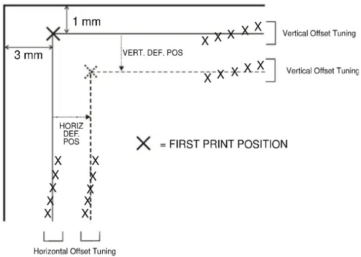
Offset Adjustments
For a precise adjustment of the position of the printed characters on a preprinted form, the printer allows to easily adjust the first line and the first printing column as follows:
- When the printer is in Setup Mode, insert a blank sheet into the printer press the ST1 key until the leds are in the configuration showed in previous SETUP STATUS table.
- Press ST2 key, the following sheet will be printed:
- Fill in the marker corresponding to the value you want to set.
The Vertical Offset Tuning values correspond to 1/60 inches and set the vertical offset of the first print line starting from the default standard position at 1 mm from the upper paper margin.
The Horizontal Offset Tuning values correspond to 1/60 inches and set the horizontal offset of the first print line starting from the default standard position at 3 mm from the left paper margin.
If you need to change the default position of the first print line the vertical offset can be set in the Vertical Position Offset lines and/or the horizontal offset in the Vertical Position Offset lines.
Both these values correspond to 1/10 inch values.
Reading the Preprinted Setup Forms
When the Printer Setup Forms have been filled in, insert them back into the printer, when the printer is in Setup Mode.
The printer is able to recognize the Setup Forms by means of the markers on these pages. The printer reads the values marked for the various parameters and configures the printer accordingly.
The settings are confirmed by a # symbol printed on the left of the corresponding marker.
The following page shows the printer setup flow-chart.
For further details concerning the parameters that can be set in the Configuration Setup, Program 1, Program 2, Program 3 and Program 2, see "Setup Parameters" before in this manual.
For further details on how to adjust the offset with this printer, see "Offset Adjustments" before in this manual.
Printer Setup Flow Chart
flowchart
graph TD
    A["Printer OFF"] --> B["Printer Ready"]
    B --> C["Setup Mode"]
    C --> D["# Parameters are set"]
    D --> E["Self Test"]
    E --> F["READY"]
    E --> G["ST1"]
    E --> H["ST2"]
    F --> I["SET"]
    G --> J["SET"]
    H --> K["SET"]
    I --> L["SET"]
    J --> M["SET"]
    K --> N["SET"]
    L --> O["SET"]
    M --> P["SET"]
    N --> Q["SET"]
    O --> R["SET"]
    P --> S["SET"]
    Q --> T["SET"]
    R --> U["SET"]
    S --> V["SET"]
    T --> W["SET"]
    U --> X["SET"]
    V --> Y["SET"]
    W --> Z["SET"]
    X --> AA["SET"]
    Y --> AB["SET"]
    Z --> AC["SET"]
    AA --> AD["SET"]
    AB --> AE["SET"]
    AC --> AF["SET"]
    AD --> AG["SET"]
    AE --> AH["SET"]
    AF --> AI["SET"]
    AG --> AJ["SET"]
    AH --> AK["SET"]
    AI --> AL["SET"]
    AJ --> AM["SET"]
    AK --> AN["SET"]
    AL --> AO["SET"]
    AM --> AP["SET"]
    AN --> AQ["SET"]
    AO --> AR["SET"]
    AP --> AS["SET"]
    AQ --> AT["SET"]
    AR --> AU["SET"]
Printer Setup through USB and RS232/C Ports
The printer Setup parameters can be changed through normal Setup as described in previous chapter or through USB or Serial 232/C port.
For this purpose is necessary install the "Godex CDC RS-232 Emulation" driver creating a virtual serial port and the "FPB-650PII Setup" software, Windows based utility able to configures the printer through USB (directly) or RS232/C Serial connection (directly or via a serial/USB adapter).
This chapter described how to install the driver and the utility.
This utility can be used also for the Firmware downloading, but this features is not covered with this manual
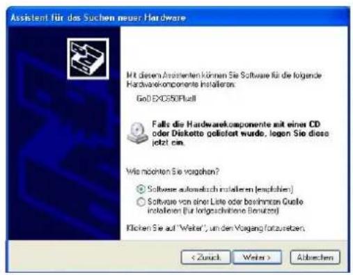
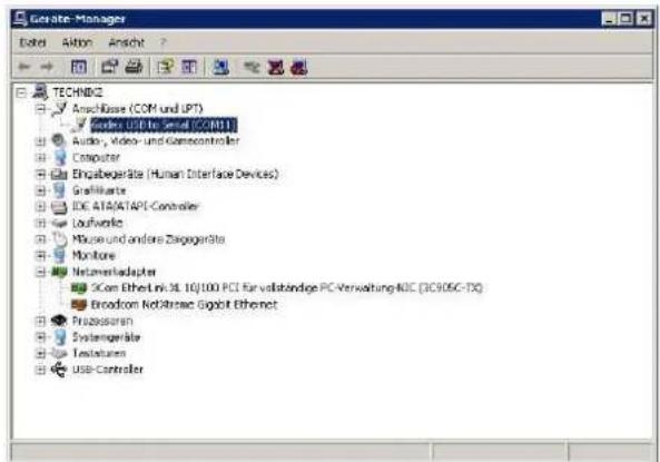
Godex CDC RS-232 Emulation Driver installation
If the printer is connected through the USB interface and the Setup mode is running, the Windows gives a message for "founds a new hardware, Godex CDC RS-232 Emulation".
Follow the steps displayed in the below masks in order to correctly install the driver.
The information file for the driver is : Godex-CDC.inf
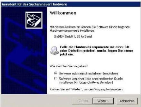
If the installation is positively ended, in the Windows hardware resources a new COMn port will be found.
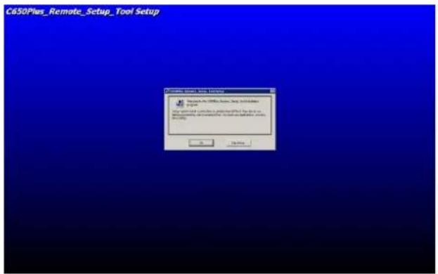
FBP-650PII Setup utility installation
Once the Godex CDC RS-232 Emulation driver has been installed, found the Setup.exe file and double click on it.
Follow the steps displayed in the below masks in order to correctly install the utility.
The utility will ask where install the program and choose the program group.
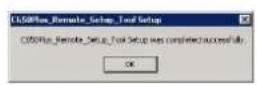
If the installation is positively ended, in the program pop-up window, the FBP-650PII Setup icon will appear. Double click on it and the FBP-650PII Setup utility will be run. See next chapter for details.
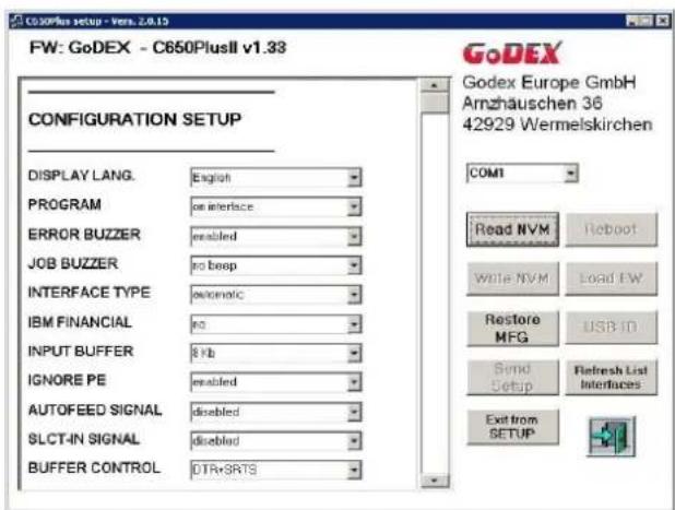
Remote Setup
When this utility is running, the following home mask will be displayed.
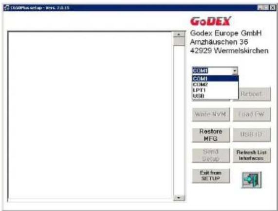
In the left top side, under Option, there is the choice of the FPB-650PII Program Setup selection.
In the right to side there are the following selection window:
1) port selection choice COMn (*)
The following action keys:
2) NVM choices for Read, Write, Send Setup, Restore MFG and Exit from Setup for Setup Parameters
3) Refresh List Interfaces
4) Load FW
5) Other selection keys are currently disables (Reboot and USB ID).
Note (\*)
The first available port number used by the Setup utility is taken from the system registry and can be different from the one displayed.
When the Read/Write/Restore MFG action will be run, the following message will be displayed by the operator panel LCD :
| REMOTE FROM: | SETUP USB |
| REMOTE FROM: | SETUP SERIAL |
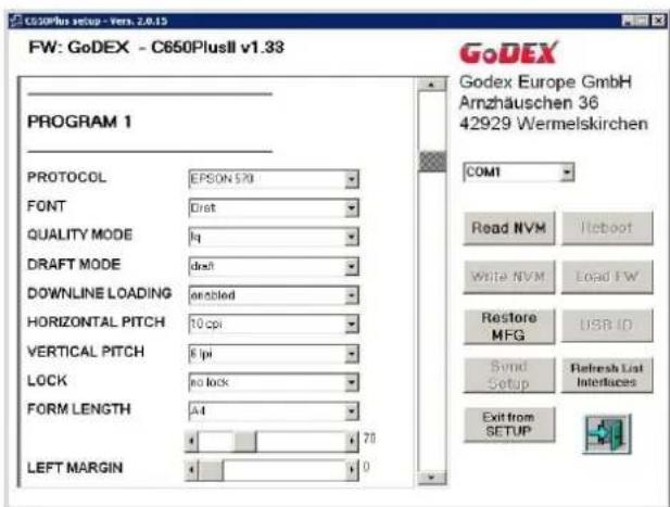
Read NVM
In the left part are displayed the current Setup parameters when the Read NVM selection are done.
The parameters are read from the selected port.
Through the vertical cursor it is possible to change each of them for all the Setup selection pages (Configuration, Program 1 to 4, Offset Tuning) and write using the selected port.
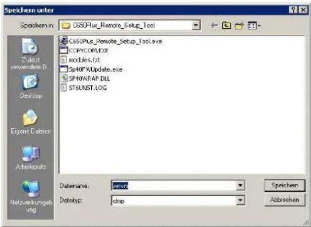
Write NVM
After reading the configuration, it is possible to do all the possible changes simply select the new values. When all modification are done, the new configuration can be stored in the printer NVM pressing the Write NVM action key.
The utility will show the "save as name" mask.
The new configuration can be saved in a specific file and path (default name is wnvm.dmp and default path is where the FBP-650PII Setup utility is stored) to be used for future configuration with a simply copy file action.
After that the printer will reboot.
The configuration file.dmp can be simply used to duplicate the same configuration on more printers. FPB-650PII unit has to be powered on in normal mode, connected to the PC through any active interface (Centronics or Serial port) and prompt:
copy file.dmp lpt1: /b command from a DOS shell,
After that the printer will reboot.
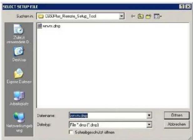
Send Setup
When Send Setup action key is activated, the host will displayed the stored configuration files.dmp; select one and then click on open to immediate send it to the printer.
After that the printer will reboot.
After that the printer will reboot.
Troubleshooting
Paper Problems
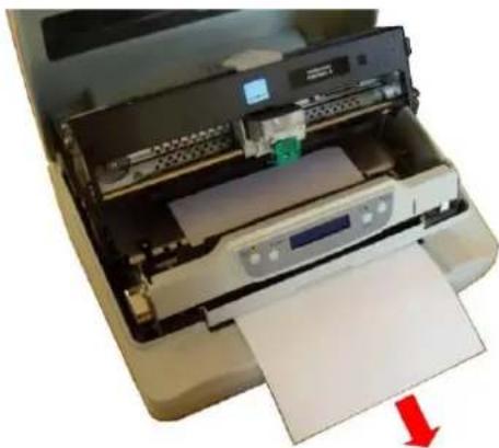
The straight paper path of this printer is designed for trouble-free handling of a great variety of documents.
Paper Jam
In case a paper jam condition occurs, proceed as follows:
- Open the printer cover. And rise the upper mechanical frame as explained in the chapter: Installing the Ribbon Cartridge, page 5.
- Remove the jammed paper, pulling it towards the fron
natural_image
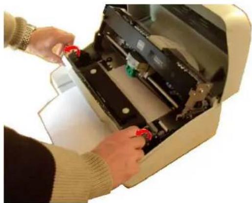
Interior view of a printer with paper feed and printer slot, showing paper sheet and printer casing (no text or symbols visible)- To have an even better access to the paper path, unlock and rotate down the Operator Panel Group
natural_image
Person installing or adjusting a mechanical device with red buttons (no visible text or symbols)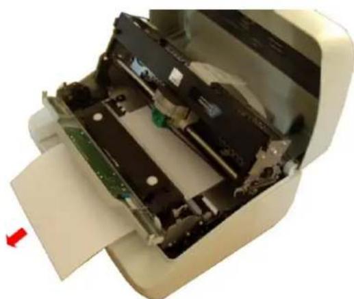
natural_image
Interior view of a printer showing internal components and a red arrow indicating left motion (no text or symbols visible)User Manual
- In case it is not possible to remove the jammed paper because you cannot reach it with your hand or it is embedded so that you cannot move it, rotate the paper belt to free the paper.
natural_image
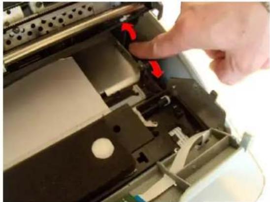
Close-up of a hand pressing down on a mechanical device with red arrows indicating motion (no visible text or symbols)-
Carefully pull down the green lever following the step 3, 4, and 5 in reverse order in order to securely close the Upper Mechanical Frame. If you do not close the Upper Mechanical Frame, the printer does not print correctly.
-
Close the printer cover.
Paper Damaged after Printing
If the paper is damaged after printing, it probably does not correspond to the specifications given in this manual or was not loaded according to the indications given.
Verify that the paper corresponds to the specifications (see "Paper Specifications" later in this manual) and has been loaded according to the indications given (see "Paper Handling" before in this manual).
Hexadecimal Dump
The hexadecimal dump function is activated when the ST2 key is press at power-on.
The printer enters in this functions and remains until it is powered-off.
The hexadecimal-dump shows all the characters sent by the host to the printer, even the not-printable ones as well as escape commands or line terminator.
Error Handling
There are two types of error:
- Recoverable errors
- Not-recoverable errors
Recoverable errors
When an error of this kind occurs:
- The printer is disabled with the ST1 and ST2 led flashing and the printer sounds a beeps.
- With operator panel with display, the following messages will be displayed; the first line indicates the error, while the second line gives more details concerning the error conditions.
Press always the READY key to reset the error condition
Recoverable error message description
| Upper line messageLower line message | Indication | Solution |
| RIBBON BROKENREPLACE RIBBON | The ribbon cartridge installed is not genuine or it is wrongly installed. | Verify if the ribbon cartridge is a Godex genuine one.Check that the ribbon is correctly insertedSee “Installing the Ribbon Cartridge”. |
| RIBBON NEAR END | The ribbon cartridge installed is near its end of life (500.000 characters to be printed) | Prepare a new Godex genuine ribbon cartridge.See “Installing the Ribbon Cartridge”. |
| RIBBON EXHAUST.REPLACE RIBBON | The ribbon cartridge installed has reached the 105% of the its nominal life. | Install a new Godex genuine ribbon cartridge.See “Installing the Ribbon Cartridge”. |
| CARRIAGE ERROR | The carriage movement has been stopped during printing causing print integrity. | Check for carriage free movement. |
| PAPER JAMREMOVE PAPER | A paper jam error condition occurs in the paper path. | Check the paper path and remove the jammed paper. |
| RS232 FAILURE DATA LOST | A buffer overflow condition occurred for the serial interface. | Check the RS232 parameters.Check the interface cable. |
| RS232 FAILURE DSR SIGNAL FLT | The DSR signal is not connected to the printer and is not ready for data transfer. | Check the interface cable connection. |
| RS232 FAILURE GENERIC ERROR | A generic error on the serial interface. | Check the RS232 parameters.Check the interface cable.Check the interface cable connection. |
Not-Recoverable errors
When an error of this kind occurs:
- The printer is halted with all the four leds flashing.
- With operator panel with display, the following messages will be displayed; the first line indicates the error, while the second line gives more details concerning the error conditions.
Power-off and Power-on the printer. It the problem remains contact the service.
Not-Recoverable error messages description
| Upper line messageLower line message | Indication | Solution |
| ENGINE FAULT | The software of the printer detects an engine failure during the initialization phase. | The problem may depends by the home carriage or paper sensor initialization errors.Check for paper inside the paper path.Check for the carriage free movement. |
| SOFTWARE FAULT**SUPERVISOR** | The software of the printer detects a failure during the displayed phase. | The problem may depends by an internal software routine error. |
| SOFTWARE FAULT**PARSER** | The software of the printer detects a failure during the displayed phase. | The problem may depends by an internal software routine error. |
| SOFTWARE FAULT*PRINT MANAGER* | The software of the printer detects a failure during the displayed phase. | The problem may depends by an internal software routine error. |
| SOFTWARE FAULT**ENGINE** | The software of the printer detects a failure during the displayed phase. | The problem may depends by an internal software routine error. |
Ribbon Cartridge Problems
The following table is useful to identify and solve print quality problems.
| Problem | Cause | Solution |
| Fading print | The ribbon is not fed | Check that the ribbon is correctly inserted (see “Installing the Ribbon Cartridge”.Turn the ribbon tension knob to verify, that the ribbon is not blocked.If the problem is not solved, change the ribbon cartridge. |
| The ribbon is used up or torn | Change the ribbon cartridge.NOTE:Godex FPB-650PII printer can signal with a specific display message or by means of a blinking led configuration when original Godex ribbon near to be replace(“Installing the Ribbon Cartridge”. | |
| The printer does not print | The ribbon cartridge is not an original Godex cartridge or it is an exhausted cartridge. | The printer checks the inserted cartridge, to avoid damaging the print head assembly due to incorrect ribbon feeding.Insert or replace with an original Godex ribbon cartridge. |
Paper Specifications
The documents must all guarantee the following characteristics:
- Use paper matching the indicated characteristics.
- They must have well defined top and left edges, with a square angle tolerance of 0.1° on all edges.
- The radius on a corner of the form must be within 9.5 mm from the left or right edge.
- The form to be printed must not contain foreign material.
- Form opacity must be at least 75%. Forms with a lower opacity may cause feed errors.
- Never print on documents with metallic or hard plastic fasteners or staples, they may damage the printer.
To get the maximum print contrast you should print on white or light colored paper. You may overstrike to improve the low contrasting paper.
- It is preferable to use single and multiple documents with the fibre running in the insertion direction of the printing unit.
- Recycled paper is permitted on principle.
- It is preferable to print on multiple forms with a narrow glue strip or top-gluing. The gluing must not cause waving in the set of forms.
Cuts Sheets
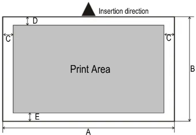
| Dimensions | Maximum | Minimum | |
| A | Form width | 244 mm (9,606 in.) | 65 mm (2,559 in.) |
| B | Form length | 470 mm (18,50 in.) | 65 mm (2.559 in.) |
| C | Distance between dot position and left or right paper edge | - | 3.0 mm (0,1181 in.) |
| D | Distance between top of the first printed line and top margin of the document | - | 1 mm (0.0394 in.) |
| E | Distance between the lower margin and the lower part of the last printed line | - | 5.8 mm (0..2283 in.)Reduced to 1.5 mm (0.0591 in.) with item SAFE BOTTOM EDGE = no |
| Weight (original) | 200 g/m^2 | 40 g/m^2 | |
| Weight(original + 1 to 6 copies) | 1^st 75 g/m^2 other 75 g/m^2 carbon 35 g/m^2 | 1^st 55 g/m^2 other 45 g/m^2 carbon 14 g/m^2 | |
| Thickness | Single form media up to 0,65 mm (0.0256 in.) | ||
| Multi form media up to 0.65 mm (0.0256 in.).Overall thicker than 0,35 mm (0.0138 in.) may cause print quality degradation in last copy. | |||
Technical Specifications
| Printing Technology | 24 pin serial dot matrix printer (needle diameter 0,25 mm) |
| Printing Speed(@10 cpi) | HSD 520 cps |
| Draft 400 cps | |
| NLQ 200 cps | |
| LQ 133 cps | |
| Line Length | 94 columns @10 cpi - 112 columns @ 12 cpi - 141 columns @ 15 cpi |
| Paper Handling | Single Sheet, envelopes, labels, (paper weight from 40gr/m^2 to 200 gr/m^2 )Cut Sheet max thickness: up to 0.65mmSingle Sheet Width: 64 - 244 mm Single sheet Length: 65 - 470 mm |
| Copies | 1 + 6 |
| Special Functions | Automatic Gap Adjustment (AGA), Auto Alignment, Auto Border Recognition, Optical Mark reading, Horizontal and Vertical, Automatic Set-up (automatic recognition of marked values) |
| Graphic resolution(dpi) | 60, 120, 180, 240, 360 (horizontal)72, 90, 180, 216, 360 (vertical) |
| Vertical spacing | 6-8-12- lines/inch, 3-4-6-8-12-lines/30mm, n/60, n/72, n/180, n/216, n/360 per inch |
| Barcodes | UPC/A, UPC/E, EAN8, EAN13, Code 39, Code 128, Postnet, Codabar, ADD-ON 2, ADD-ON 5, Code 11, Code 93, BCD, MSI, 2/5 Interleaved, 2/5 Matrix, 2/5 Industrial |
| Character set(IBM and Epson) | PC standard set (CS1-CS2) - 13 National Epson sets - CP437 (USA) - CP437G (Greek) - CP437 Slavic - CP850 (Multilanguage) - CP851 (Greek) - CP852 (Latin 2) - CP853 (Turkish) - CP855 (Russian) - CP857 (Turkish) - CP 858 (Euro) - CP860 (Portuguese) - CP862 (Hebrew) - CP863 (French/Canadian) - CP864 (Arabic) - CP865 (Norwegian) - CP866 (Cyrillic) - CP867 (Turkish) - CP876 (OCRA) - CP877 (OCRB) - CP1098 (Farsi Arabic) - CP1250 (Central Europe) - CP1251 (Cyrillic) - CP1252 (Windows Latin1 Ansi) - Gost - Tass - Mazowia - ISO 8859/1/2/3/4/5/6/7/8/9/15 - 96GREEK- Ukrainian - ID 12 - ID 14 - ID 17 - Roman-8 - Sanyo - Ku - Philip |
| Character set(Olivetti) | CS000 - CS010 International, CS020 Germany, CS030 Portugal, CS040 Spain1, CS050 Denmark/Norway, CS060 France, CS070 Italy, CS080 Sweden/Finland, CS090 Switzerland, CS100 Great Britain, CS110 USA ASCII, CS140 Greece, CS150 Israel, CS170 Spain 2, CS200 Jugoslavia, CS410 Olivetti TCV 370, CS510 SDC, CS520 Turkey, CS540 CIBC, CS680 OLI-UNIX, CS701 PC-220 Spain2, CS711 PC-Denmark/Norway, CS712 PC-Denmark OPE, CS771 PC-210 Greek |
| Resident Fonts | Draft, Courier, Gothic, Prestige, Presentor, Script, OCR-A, OCR-B, Boldface |
| Resident Emulations | IBM ® Personal Printer 2390+, Proprinter XL24E, Proprinter XL24AGM, IBM ® 4722, Epson ® LQ2550/LQ1170 and Olivetti ® PR40 PLUS/PR2/PR2845, IBM 9068, HPR 4915 |
| Interfaces | Parallel IEEE 1284 bidirectional, Serial RS232C, USB 2.0 Full Speed Automatic Interface Switching |
| Optional: 2nd RS232, Ethernet 10/100 LAN, 2nd USB 2.0 High Speed, up to 3 USB ports Hub/Hosts for external devicesInput Buffer up to 64 KbytesPlug&Play - Drivers Windows 2000, XP, VISTA (32/64 bits), Windows 7 (32/64 bits) | |
| Reliability | >10.000 hours MTBF (mean time between failure) |
| Print Head Life | >400 Million characters or > Billion strokes/wire |
| Consumables | Type: black ribbon cartridge Life: >10 Million characters |
| Noise Level<54 dbA | <54 dbA |
| Power Supply | Universal from 100 to 230 V Frequency: 50 / 60 Hz |
| Power consumption: | 45 W max. (printing DIN letter) - < 3 W (standby - 0 W (switched off) |
| Physical Dimensions & Weight | 8 Kg (9.2 Kg packed) |
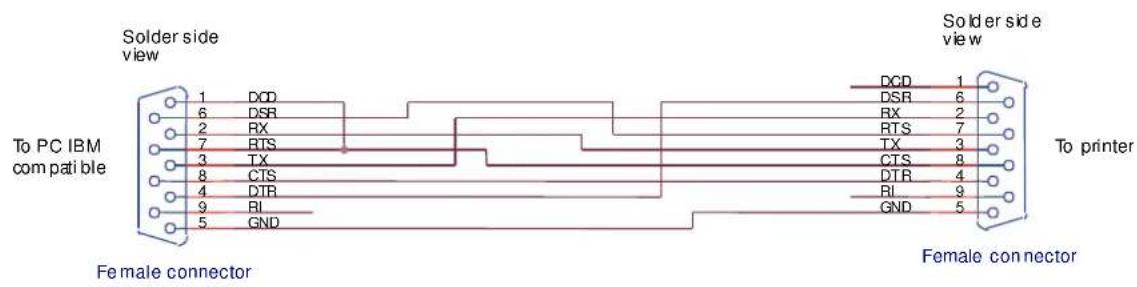
Serial Interface Connection
- User Information according to European Directive 2002/95/EC and 2003/108/EC
- Godex Product Information
- FCC Notes
- Canadian D.O.C. Radio Interference Regulation
- Table of Contents
- Printer Presentation
- Unpacking the Printer
- Notify any damage to your supplier.
- Printer Parts
- Front View
- Rear view
- Inside view
- Printer Installation
- Choosing a Suitable Location
- Installing the Power Cable
- Always use a grounded outlet
- Installing the Ribbon Cartridge
- User Manual
- Remark
- Paper Handling
- Loading Paper
- The Operator Panel
- Software Driver Installation
- Connection to the Host
- Setting the Interface Parameters
- Parallel Interface
- Serial Interface
- USB Interface
- Printer Setup
- Entering the Printer Setup Mode
- Printing the Test Page
- SELF TEST
- Printing the Printer Setup Forms
- Remark: do not fill this empty marker
- Filling in the Printer Setup Forms
- Setup Parameters
- Offset Adjustments
- Reading the Preprinted Setup Forms
- Printer Setup Flow Chart
- Printer Setup through USB and RS232/C Ports
- Godex CDC RS-232 Emulation Driver installation
- FBP-650PII Setup utility installation
- Remote Setup
- Note (\*)
- Read NVM
- Write NVM
- Send Setup
- Troubleshooting
- Paper Problems
- Paper Jam
- Paper Damaged after Printing
- Hexadecimal Dump
- Error Handling
- Recoverable errors
- Press always the READY key to reset the error condition
- Not-Recoverable errors
- Power-off and Power-on the printer. It the problem remains contact the service.
- Ribbon Cartridge Problems
- Paper Specifications
- Cuts Sheets
- Serial Interface Connection
Brand : Godex
Model : C-650 Plus II
Category : Printer