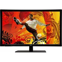
LED215W2 - Monitor V7 - Free user manual and instructions
Find the device manual for free LED215W2 V7 in PDF.


| Product Type | LED Monitor |
| Model | LED215W2 |
| Brand | V7 |
| Screen Size (diagonal) | 21.5 inches (54.6 cm) |
| Resolution | 1920 x 1080 (Full HD) |
| Panel Type | TN or IPS (typical) |
| Aspect Ratio | 16:9 |
| Refresh Rate | 60 Hz |
| Brightness | 250 cd/m² |
| Contrast Ratio | 1000:1 (typical) |
| Viewing Angles | 170° (H) / 160° (V) |
| Inputs | VGA, DVI, HDMI |
| Power Consumption (typical) | 25 W |
| Power Supply | External AC adapter (100-240V) |
| Dimensions (with stand) | 20.0 x 7.0 x 15.0 inches (508 x 178 x 381 mm) |
| Weight (with stand) | 5.5 lbs (2.5 kg) |
| VESA Mount Compatibility | 100 x 100 mm |
| Anti-Glare | Yes |
| Built-in Speakers | No |
| Stand Features | Tilt adjustment (optional) |
| Cleaning Instructions | Use a soft, dry cloth; avoid liquid cleaners |
| Safety Features | Anti-flicker, low blue light modes |
| Spare Parts Availability | Power adapter, stand, screws |
| Reparability | User-replaceable stand; internal repairs by professionals |
| Warranty | 1 year limited warranty |
Frequently Asked Questions - LED215W2 V7
User questions about LED215W2 V7
0 question about this device. Answer the ones you know or ask your own.
Ask a new question about this device
Download the instructions for your Monitor in PDF format for free! Find your manual LED215W2 - V7 and take your electronic device back in hand. On this page are published all the documents necessary for the use of your device. LED215W2 by V7.
USER MANUAL LED215W2 V7
F.C.C STATEMENT IMPORTANT SAFEGUARDS
1. Introduction....1
1.1 Features .... 1
1.2 Checking List....1
2. Installation....2
2.1 Install the pedestal 2
2.2 Connect your monitor to computer....2
3. Front Panel overview .... 3
4. Access Features .... 4
4.1 Switching the Monitor On/Off 4
4.2 Power Indicator 4
4.3 Menu Features .... 4
4.4 OSD Functional Control Description ....5
4.5 Preset Modes Timing Chart....7
4.6 Plug and Play 8
5.Technical Information 9
5.1 D-SUB Signal connector pin assignment....9
5.2 Visual Inspection....10
5.3 Trouble shooting....11
FEDERAL COMMUNICATIONS COMMISSION
This equipment has been tested and found to comply with the limits of a Class B digital device, pursuant to Part 15 of the FCC Rules. These limits are designed to provide reasonable protection against harmful interference in a residential installation. This equipment generates uses and can radiate radio frequency energy and, if not installed and used in accordance with the instructions, may cause harmful interference to radio communications. However, there is no guarantee that interference will not occur in a particular installation. If this equipment does cause harmful interference to radio or television reception, which can be determined by turning the equipment off and on, the user is encouraged to try to correct the interference by one or more of the following measures:
- Reorient/Relocate the receiving antenna.
- Increase the separation between the equipment and receiver.
- Connect the equipment into an outlet on a circuit different from that to which the receiver is connected.
- Consult the dealer of an experienced radio/TV technician for help.
CAUTION: Changes or modifications not expressly approved by the manufacturer responsible for compliance could void the user's authority to operate the equipment.
NOTE: The use of a non-shielded interface cable with this equipment is prohibited
Warnings:
- Read all of these instructions Save these instructions for later use, please.
- Unplug this monitor from the wall outlet before cleaning. Do not use liquid cleaners or aerosol cleaners. Use a damp cloth for cleaning.
- Do not use attachments not recommended by the monitor manufacturer as they may cause hazards.
- Do not use this monitor near water. For example near a bathtub, washbowl, kitchen sink, or laundry tub, in a wet basement, or near a swimming pool, etc...
- Do not place this monitor on an unstable cart, stand, or table. The monitor may fall, causing serious injury to a child or adult and serious damage to the appliance. Use only with a cart or stand recommended by the manufacturer or sold with monitor. Wall or shelf mounting should follow the manufacturer's instructions, and should use a mounting kit approved by the manufacturer.
- Slots and openings in the cabinet and the back or bottom are provided for ventilation, and to insure reliable operation of the television receiver and to protect it from overheating, these openings must not be blocked or covered. The openings should never be blocked by placing the monitor on a bed, sofa, rug, or other similar surface. This monitor should never be placed near or over a radiator or heat register. This monitor should not be placed in built-in installation such as a bookcase unless proper ventilation is provided.
- This monitor should be operated only from the type of power source indicated on the marking label. If you are not sure of the type of power supplied in your home, consult your monitor dealer or local power company.
- The national approved class II power cord is provided with the product. Only use the power cord provided with the product. If need to replace the power cord, contact the monitor dealer.
- Do not allow anything to rest on the power cord. Do not locate this monitor where the cord will be abused by persons working on it.
- Follow all warnings and instructions marked on the monitor.
- For added protection for this monitor, when it is left unattended and unused for long periods of time, unplug it from the wall outlet. This will prevent damage to the monitor due to power-line surges.
- Do not overload wall outlets and extension cords as this can result into fire or electric shock.
- Never push objects of any kind into this monitor through cabinet slots as they may touch dangerous voltage points or short out parts that could result in a fire or electric shock. Never spill liquid of any kind on the monitor.
- Do not attempt to service this monitor yourself since opening or removing
covers may expose you to dangerous voltage or other hazards. Refer all servicing to qualified service personnel.
- Unplug this monitor from the wall outlet and refer servicing to qualified service personnel under the following conditions:
a. When the power cord or plug is damaged or frayed.
b. If liquid has been spilled into the monitor.
c. If the monitor has been exposed to rain or water.
d. If the monitor does not operate normally by following the operating instructions. Adjust only those controls that are covered by the operating instructions as improper adjustment of other controls may result in damage and will often require extensive work by a qualified technician to restore the monitor to normal operation.
e. If the monitor has been dropped or the cabinet has been damaged.
f. When the monitor exhibits a distinct change in performance this indicated a need for service.
-
When replacement parts are required, be sure the service technician has used replacement parts specified by the manufacturer that have the same characteristics as the original parts. Unauthorized substitutions may result in fire, electric shock, or other hazards.
-
Upon completion of any service or repairs to this monitor, ask the service technician to perform routine safety checks to determine that the monitor is in safe operating condition.
-
The socket outlet shall be near the equipment and shall be easily accessible.
-
The power supply cord is used as the main disconnect device.
1. Introduction
1.1 Features
- Microprocessor based with OSD (On Screen Display) control.
Compatible with standard IBM VGA, extended VGA, super VGA, IBM XGA, SXGA modes, as well as VESA resolution standards.
➢ Universal power supply 100-240 Vac, 50/60Hz(Power box)/DC 12V(Monitor)
Microsoft Windows 95/98/2000/XP/VISTA compatible & VESA Display Data channel (DDC)1/2B compatible
1.2 Checking List
Please make sure the following items are included with your LED monitor:
☑ Your monitor
☑ AC-DC adapter
User manual
☑ Signal cable
If any of these items are missing, please contact with your dealer for technical support and customer service.
2. Installation
2.1 Install the Pedestal
To attach the base to your monitor, please follow the steps for installation of the pedestal as below:

natural_image
Illustration of a computer monitor, CD/DVD, and an open hard disk with a screwdriver (no text or symbols)2.2 Connect your monitor to computer
- Turn off the computer and unplug the power cable.
- Connect the signal cable to the signal port on the back of the computer.
- Connect the DC plug of the AC-DC adapter to the DC 12V port at the rear of the monitor. Connect the power cord to the AC-DC adapter and wall outlet.
- Press the power button, located on the bottom side of the main unit to turn the monitor on and then turn the computer on. If the monitor displays an image, the monitor is successfully installed. If no image is displayed, check all connections.
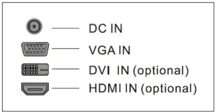
Connecting the monitor to the computer and the power supply
3. Front Panel Overview

flowchart
graph TD
    A["MENU"] --> B["1"]
    B --> C["2"]
    C --> D["3"]
    D --> E["4"]
    E --> F["5"]
    G["AUTO"] --> H["↑"]
    H --> I["↓"]
1、Menu Button
To push menu button turns on the menu, and it activates the items you highlight.
To choose which function you need. You may choose DOWN counterclockwise or UP clockwise.
3、Auto Button
Auto adjusts the display mode to its utmost performance according to VGA setting.
4、Power Button(⏻)
Use this button to turn the monitor on and off.
5、Power indicator
This light glows green or blue during normal operation and glows black during power off, glows orange during power saving mode.
4. Access Features
4.1 SWITCHING THE MONITOR ON/OFF
This power button is used for switching the monitor on and off.
Note: The power button does not disconnect the device from the mains voltage. To completely disconnect the mains voltage. Please remove the power plug from the socket.
4.2 POWER INDICATOR
This indicator lights up green or blue when the monitor operates normally. If the monitor is in power saving mode, this indicator change to orange. When monitor is turn off, this indicator changes the color to dark.
4.3 MENU FEATURES
The following features can all be accessed by using your monitor's on screen menu system. Once are finished. Making adjustments to a feature, selecting the exit icon to turn off the menu.
Please follow the procedure of selection and adjust an item using the OSD system as below steps for main functions adjustment.
- Press the MENU button to activate the OSD menu. The main menu appears on the screen with icons for the setting functions.
- If necessary, use the DOWN (▼) or UP (▲) button to mark another icon.
- Press the MENU button to activate the highlighted icon.
- Use the DOWN (▼) or UP (▲) button to make the desired setting.
- Select the EXIT symbol to exit the OSD menu.
- Repeat step 2 through 5 to make further adjustments.
All changes are stored immediately.
4.4 OSD Functional Control Description
1. Main Menu
OSD main menu of controls gives you an overview of the selection of controls available. When you want to make adjustment of the screen image, press and release button Menu

2. OSD Adjustment

You can choose where you would like OSD image to appear on your screen.
H-Position

To move the OSD image horizontally left or right.
V-Position

To move the OSD image vertically up or down.
Exit :


To exit the sub menu
3. Language

You can choose one of the muti-languages you need.
4. Reset

Reset the currently highlighted control to the factory setting. User must be using factory preset video mode to use this function.
5. Auto

Auto adjust display mode to its utmost performance according to VGA setting. In the event of the display image needs further adjustment.
Input Select → (Optional)
For switching between DVI (or HDMI) and VGA when using both connections.

6. Color Select
Color Select Menu
Select user mode

User color you can adjust to individual color gum intensity by yourself. Increase or decrease red, green or blue depending upon which color is selected.
Cool:
This control adjusts the color temperature of the screen image. This item are preset by factory, you can not adjust these setting. The performance is bluer and brighter.
Warm: The performance is redder and closer to paper white.
Native: to give the white color a natural tint.
sRGB: Display standard color.
MWE: Include STANDARD, SCENERY, THEATER, GAME, NIGHT, DCR, FLIT etc. display models (Selective function)
7. Phase

To improve focus clarity an image stability.
8. H. Size

To increase or decrease the horizontal size of image.
9. V. Position

To move the picture image vertically up or down.
10. H. Position

To move the picture image horizontally left or right.
11. Contrast

Adjust the image brightness in relation to the background.
12. Brightness

Adjust the overall image and background screen brightness
4.5 Preset Modes Timing Chart
The screen image has been optimized during manufacture for the display modes listed below.
- Aspect ratio 16:10
| Item | Dot X Line | Refresh rate(Hz) |
| 1 | 720 x 400 | 70 |
| 2 | 640 x 480 | 60, 75 |
| 3 | 800 x 600 | 60, 75 |
| 4 | 1024 x 768 | 60, 75 |
| 5 | 1280 x 1024 | 60, 75 |
| 6 | 1440 x 900 | 60 |
| 7 | 1680 x 1050 | 60 |
| 8 | 1920 x 1200 | 60 |
NOTE: All preset modes are subject to change without notice.
19"w: Items 1\~6; 20"w, 22"w: Items 1\~7; 24"w, 26"w: Items 1\~6, 8;
- Aspect ratio 16:9
| Item | Dot X Line | Refresh rate(Hz) |
| 1 | 720 x 400 | 70 |
| 2 | 640 x 480 | 60, 75 |
| 3 | 800 x 600 | 60, 75 |
| 4 | 1024 x 768 | 60, 75 |
| 5 | 1360 x 768 | 60 |
| 6 1600x900 60 | ||
| 7 | 1280 x 1024 | 60,75 |
| 8 | 1440 x 900 | 60 |
| 9 | 1680 x 1050 | 60 |
| 10 | 1920 x 1080 | 60 |
NOTE: All preset modes are subject to change without notice.
18.5"w: 1\~5; 20"w, 1\~4, 6; 21.5"w, 23.6"w: 1\~4, 7\~10;
4.6 Plug and Play
This monitor features the VESA DDC (Display Data Channel) standard, which when used with a DDC compatible video card, will simplify the monitor's set up. With VESA DDC 1/2B, when the monitor is powered up, it will automatically notify a windows 9X/2000/XP host computer of its scanning frequencies, capabilities and characteristics. Windows 9X/2000/XP will automatically recognize the connection of the monitor and select the appropriate display resolution.
5. Technical Information
5.1 D-SUB Signal connector pin assignment
| PIN | Signal (D-sub) | PIN | Signal (D-sub) |
| 1 | Red | 9 | 5 VDC |
| 2 | Green | 10 | Ground |
| 3 | Blue | 11 | Ground |
| 4 | Ground | 12 | SDA (For DDC) |
| 5 | Self Test | 13 | H. Sync. |
| 6 | Red Ground | 14 | V. Sync. |
| 7 | Green Ground | 15 | SCL (For DDC) |
| 8 Blue | Ground |

D-SUB connector
DVI-D Signal connector pin assignment (Optional)
| PIN | Signal (DVI) | PIN | Signal (DVI) |
| 1 | TMDS Data 2- | 13 | TMDS Data 3+ |
| 2 | TMDS Data 2+ | 14 | +5V Power |
| 3 | TMDS Data 2/4 shield | 15 | Ground |
| 4 | TMDS Data 4- | 16 | Hot Plug Detect |
| 5 | TMDS Data 4+ | 17 | TMDS Data 0- |
| 6 | DDC Clock | 18 | TMDS Data 0+ |
| 7 | DDC Data | 19 | TMDS Data 0/5 shield |
| 8 | Analog Vertical Synchronal | 20 | TMDS Data 5- |
| 9 | TMDS Data 1- | 21 | TMDS Data 5+ |
| 10 | TMDS Data 1+ | 22 | Clock shield |
| 11 | TMDS Data 1/3 shield | 23 | Clock+ |
| 12 | TMDS Data 3- | 24 | Clock- |

DVI-D connector
5.2 Visual Inspection
Permanently unlit or lit pixels
The standard of production techniques today cannot guarantee an absolutely fault-free screen display. A few isolated constant lit or unlit pixels may be present. The maximum permitted number of pixels faults is stipulated in the stringent international standard ISO-9241-302 (Class II).
Example: a 17" flat-screen monitor with a resolution of 1280 x 1024 has 1280 x 1024 = 1310720 pixels. Each pixel consists of three subpixels (red, green and blue), so there are about 4 million dots in total.
According to ISO-9241-302 (Class II), a maximum of 6 pixels and 7 subpixels may be defective, i. e. a total of 25 faulted dots. This corresponds to approx. 0.002 % of the entire screen surface.
5.3 Trouble Shooting
Before calling for service, check the information in this section to see if you can remedy any problems by yourself. If you need assistance, please call the dealer where you purchased the LED monitor.
There is no SCREEN image
Please check these items:
The power cord is securely connected the monitor, the adaptor, and the wall outlet.
Check the signal cable connection between the monitor and the computer.
Adjust the brightness and contrast controls.
Monitor in power saving mode.
Display image is too large or small
Use the OSD controls to adjust Auto Setup.
The colors are discord
Signal cable properly connected?
Use OSD controls to adjust the color control setting.
The image is too light or too dark
Use OSD controls to adjust the brightness and contrast.
Regulatory Information: Disposal of Waste Electrical and Electronic Equipment (WEEE)
The Waste Electrical and Electronic Equipment (WEEE) Directive aims to minimize the impact of electrical and electronic goods on the environment, by increasing re-use and recycling and by reducing the amount of WEEE going to landfill. The symbol on your V7 product or its packaging signifies that this product must be disposed separately from ordinary household wastes at its end of life. Please kindly be aware that this is your responsibility to dispose electronic equipment at recycling centers so as to help conserve natural resources.
Each country in the European Union should have its collection centers for electrical and electronic equipment recycling. For information about your recycling drop off area, please contact your related electrical and electronic equipment waste management authority or the retailer where you bought the product. Authorized Representative in European Community: Ingram Micro Pan Europe GmbH, Heisenbergbogen 3, D-85609 Dornach / Munich, Germany. (www.V7-world.com)
www.V7-world.com
- F.C.C STATEMENT IMPORTANT SAFEGUARDS
- Introduction....1
- Installation....2
- Front Panel overview .... 3
- Access Features .... 4
- 5.Technical Information 9
- FEDERAL COMMUNICATIONS COMMISSION
- Warnings:
- Introduction
- Features
- Checking List
- Installation
- Install the Pedestal
- Connect your monitor to computer
- Front Panel Overview
- Access Features
- SWITCHING THE MONITOR ON/OFF
- POWER INDICATOR
- MENU FEATURES
- OSD Functional Control Description
- Main Menu
- OSD Adjustment
- H-Position
- V-Position
- Language
- Reset
- Auto
- Input Select → (Optional)
- Color Select
- Color Select Menu
- Select user mode
- Cool:
- Phase
- H. Size
- V. Position
- H. Position
- Contrast
- Brightness
- Preset Modes Timing Chart
- Plug and Play
- Technical Information
- D-SUB Signal connector pin assignment
- Visual Inspection
- Trouble Shooting
- Please check these items:
- Display image is too large or small
- The colors are discord
- The image is too light or too dark
Brand : V7
Model : LED215W2
Category : Monitor