1739L - Screen ELO - Free user manual and instructions
Find the device manual for free 1739L ELO in PDF.


| Product Type | 17-inch LCD Touchscreen Monitor |
| Brand | Elo |
| Model | 1739L |
| Display Size | 17 inches (43.2 cm) diagonal |
| Resolution | 1280 x 1024 (SXGA) |
| Aspect Ratio | 5:4 |
| Touch Technology | Resistive (5-wire) or IntelliTouch Surface Acoustic Wave |
| Brightness | 300 cd/m² (typical) |
| Contrast Ratio | 800:1 (typical) |
| Response Time | 10 ms (typical) |
| Viewing Angle | 160° horizontal / 140° vertical (typical) |
| Inputs | VGA (DB-15), DVI-D |
| USB Ports | 1 x USB Type-B (touch controller) |
| Dimensions (W x H x D) | 15.7 x 13.0 x 10.2 inches (399 x 330 x 259 mm) |
| Weight | 10.5 lb (4.8 kg) |
| Power Supply | External AC adapter (100-240V, 50/60Hz) |
| Power Consumption | 30W (typical), <1W (standby) |
| VESA Mount | 75 x 75 mm |
| Cleaning Instructions | Clean with soft dry cloth; avoid solvents |
| Safety | UL/cUL, FCC Class B, CE, RoHS compliant |
| Spare Parts | Contact Elo support for replacement power adapter, touch controller board |
Frequently Asked Questions - 1739L ELO
User questions about 1739L ELO
0 question about this device. Answer the ones you know or ask your own.
Ask a new question about this device
Download the instructions for your Screen in PDF format for free! Find your manual 1739L - ELO and take your electronic device back in hand. On this page are published all the documents necessary for the use of your device. 1739L by ELO.
USER MANUAL 1739L ELO
Touchmonitor User Guide
1739L 17" LCD Rear-mount Touchmonitor
User Guide
17" LCD REAR-MOUNT TOUCHMONITOR
1739L Family 3000 Series
Revision D
P/N E247574
Copyright © 2007 Tyco Electronics. All Rights Reserved.
No part of this publication may be reproduced, transmitted, transcribed, stored in a retrieval system, or translated into any language or computer language, in any form or by any means, including, but not limited to, electronic, magnetic, optical, chemical, manual, or otherwise without prior written permission of Elo TouchSystems.
Disclaimer
The information in this document is subject to change without notice. Elo TouchSystems makes no representations or warranties with respect to the contents hereof, and specifically disclaims any implied warranties of merchantability or fitness for a particular purpose. Elo TouchSystems reserves the right to revise this publication and to make changes from time to time in the content hereof without obligation of Elo TouchSystems to notify any person of such revisions or changes.
Trademark Acknowledgments
IntelliTouch is a trademark of Tyco Electronics. Other product names mentioned herein may be trademarks or registered trademarks of their respective companies.
Table of Contents
Chapter 1
Introduction 7
Product Description ....7
Precautions 7
About the Product 8
Chapter 2
Installation and Setup 9
Unpacking Your Touchmonitor....9
Touch Interface Connection ....10
Product Overview 11
Main Unit 11
Rear View ....11
Installing the Driver Software ....12
Installing the Serial Touch Driver ....13
Installing the Serial Touch Driver for Windows
XP, Windows 2000, Me, 95/98 and NT 4.0 .....13
Installing the Serial Touch Driver for MS-DOS
and Windows 3.1....14
Installing the USB Touch Driver ....15
Installing the USB Touch Driver for Windows
XP, Windows 2000, Me, 95/98 and NT 4.0 .....15
Chapter 3
Operation 17
About Touchmonitor Adjustments ....17
Rear Panel Controls....18
Remote OSD Buttons(option) 18
Controls and Adjustment ....19
On Screen Display (OSD) Menu Functions......19
On Screen Display (OSD) Control Options .....20
Preset Modes ......21
Power Management System ......22
Chapter 4
Troubleshooting 23
Solutions to Common Problems ....23
Appendix A
Native Resolution ......25
Appendix B
Touchmonitor Safety 27
Care and Handling of Your Touchmonitor ....28
Warning 28
Appendix C
Touchmonitor Specifications ....30
IntelliTouch TouchScreen Specifications ....31
CarrollTouch TouchScreen Specifications......32
Surface Capacitive TouchScreen Specifications .33
SecureTouch TouchScreen Specifications......34
AccuTouch Touchscreen Specification ....35
17" LCD Touchmonitor (ET1739L-XCWA-X-G)
Dimensions 36
Regulatory Information 37
Warranty 39
Index 41
1
INTRODUCTION
Product Description
Your new touchmonitor combines the reliable performance of touch technology with the latest advances in (LCD) display design. This combination of features creates a natural flow of information between a user and your touchmonitor.
This LCD monitor incorporates a 17" color active matrix thin-film-transistor (TFT) to provide superior display performance. A maximum resolution of SXGA 1280 x 1024 is ideal for displaying graphics and images. Other outstanding features that enhance this LCD monitor's performance are Plug & Play compatibility, and On Screen Display (OSD) controls.
Precautions
Follow all warnings, precautions and maintenance as recommended in this user's manual to maximize the life of your unit. See Appendix B for more information on touchmonitor safety.
Your LCD rear-mount touchmonitor is a 17" SXGA TFT color display with the following features:
- The internal microprocessor digitally controls auto-scanning for horizontal scan frequencies between 31.5 KHz and 80 KHz, and vertical scan frequencies between 56.3 Hz and 75.0 Hz. In each frequency mode, the microprocessor-based circuitry allows the monitor to function at the precision-of a fixed frequency.
- High contrast color TFT LCD display supports resolutions up to SXGA 1280 x 1024. Compatible with VGA, SVGA, XGA, SXGA (non-interlaced) and most Macintosh compatible color video cards.
- Power management system conforms to VESA DPMS standard.
- Supports DDC1/2B for Plug & Play compatibility.
- Advanced On Screen Display (OSD) control for picture quality adjustment.
For full Product Specifications refer to Appendix C.
2
INSTALLATION AND SETUP
This chapter discusses how to install your LCD touchmonitor and how to install the driver software.
Unpacking Your Touchmonitor
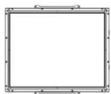
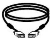
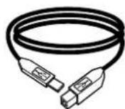
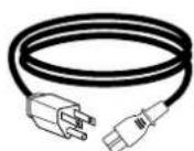
Check that the following 9 items are present and in good condition:
natural_image
Empty rectangular frame with decorative border (no text or symbols)LCD monitor Video cable
USB cable
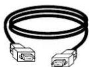
Serial cable
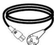
European power cable
ower cable US/Canada
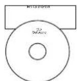
Touch Tools CD+Quick Install Guide
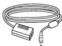
Brick power supply
Note: Before connecting the cables to your touchmonitor and PC, be sure that the computer and touchmonitor are turned off.
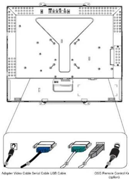
- Connect one end of the power adapter to the monitor and the other end to the connector of the power cord.
- Connect one end of either the touchscreen serial (RS232) cable or the touchscreen USB cable (but not both) to the rear side of the computer and the other end to the LCD monitor. Tighten by turning the two thumb screws clockwise to ensure proper grounding (USB cable does not have thumb screws).
- Connect one end of the video cable to the rear side of computer and the other to the LCD monitor. Tighten by turning the two thumb screws clockwise to ensure proper grounding.
- Press the power button on the rear panel to turn the monitor power on.
- Connect one end of OSD remote control key(option) to the monitor.
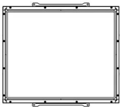
Main Unit
natural_image
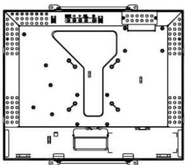
Empty rectangular frame with corner brackets and mounting holes (no text or symbols)Rear View
natural_image
Technical line drawing of a mechanical component with no visible text or symbolsElo TouchSystems provides driver software that allows your touchmonitor to work with your computer. Drivers are located on the enclosed CD-ROM for the following operating systems:
- Windows XP
- Windows 2000
- Windows Me
- Windows 98
- Windows 95
- Windows NT 4.0
The latest versions of drivers and driver information for other operating systems are available on the Elo TouchSystems web site at www.elotouch.com.
Your Elo touchmonitor is Plug-and-Play compliant. Information on the video capabilities of your touchmonitor is sent to your video display adapter when Windows starts. If Windows detects your touchmonitor, follow the instructions on the screen to install a generic Plug-and-Play monitor.
Refer to the appropriate section for driver installation instructions.
Depending upon whether you connected the serial communication cable or the USB communication cable, you should install only the serial driver or the USB driver.
Installing the Serial Touch Driver for Windows XP, Windows 2000, Me, 95/98 and NT 4.0
NOTE: For Windows 2000 and NT 4.0 you must have administrator access rights to install the driver.
1 Insert the Elo CD-ROM in your computer's CD-ROM drive.
2 If the AutoStart feature for your CD-ROM drive is active, the system automatically detects the CD and starts the setup program.
3 Follow the directions on the screen to complete the driver setup for your version of Windows.
4 If the AutoStart feature is not active:
5 Click Start > Run.
6 Click the Browse button to locate the EloCd.exe program on the CD-ROM.
7 Click Open, then OK to run EloCd.exe.
8 Follow the directions on the screen to complete the driver setup for your version of Windows.
To install Windows 2000 and Windows XP, you must use the "update driver" method; you will not find a setup.exe file within the download.
Installing the Serial Touch Driver for MS-DOS and Windows 3.1
You must have a DOS mouse driver (MOUSE.COM) installed for your mouse if you wish to continue using your mouse along with your touchmonitor in DOS.
To install Windows 3.x and MS-DOS from Windows 95/98, follow the directions below:
1 Insert the CD-ROM in your computer's CD-ROM drive.
2 From DOS, type d:\EloDos_W31 to change to the correct directory on the CD-ROM (your CD-ROM drive may be mapped to a different drive letter).
3 Type install and press Enter to start the installation.
4 Align the touchscreen.
You must have already completed Steps 1 and 2 before proceeding.
To run the INSTALL program:
1 Type INSTALL at the DOS prompt in the directory containing the driver install files.
2 INSTALL asks you to select the software to install. Then choose d:\EloDos_W31 from the displayed list.
3 INSTALL also asks you for the paths to use during installation, or you may use its defaults.
INSTALL creates directories as necessary, and warns you if they exist.
If you are updating your software, you may wish to specify the paths containing the earlier versions, and overwrite the obsolete files. All executable programs are upward compatible. For a list of differences from each previous version of the drivers, be sure to select "Differences from Previous Versions" during the installation process.
INSTALL updates your AUTOEXEC.BAT file with the drivers you select. INSTALL makes a copy of your original AUTOEXEC.BAT file, called AUTOEXEC.OLD. If you already have Elo driver commands in your AUTOEXEC.BAT file, they will be commented out.
When INSTALL is finished, it leaves a file called GO.BAT in the subdirectory you specified. GO loads the touchscreen driver, runs the calibration program ELOCALIB, and gives you some final instructions.
If you are using Windows 3.1, you will also calibrate the touchscreen within Windows 3.1 with the Touchscreen Control Panel.
Installing the USB Touch Driver for Windows XP, Windows 2000, Me, 95/98 and NT 4.0
1 Insert the Elo CD-ROM in your computer's CD-ROM drive.
If Windows 98, Windows Me or Windows 2000 starts the Add New Hardware Wizard.
2 Choose Next. Select "Search for the best driver for your device (Recommended)" and choose Next.
3 When a list of search locations is displayed, place a checkmark on "Specify a location" and use Browse to select the \EloUSB directory on the Elo CD-ROM.
4 Choose Next. Once the Elo USB touchscreen driver has been detected, choose Next again.
5 You will see several files being copied. Insert your Windows 98 CD if prompted. Choose Finish.
If Windows 98, Windows Me or Windows 2000 does not start the Add New Hardware Wizard.
NOTE: For Windows 2000 you must have administrator access rights to install the driver.
1 Insert the Elo CD-ROM in your computer's CD-ROM drive. If the AutoStart feature for your CD-ROM drive is active, the system automatically detects the CD and starts the setup program.
2 Follow the directions on the screen to complete the driver setup for your version of Windows.
If the AutoStart feature is not active:
1 Click Start > Run.
2 Click the Browse button to locate the EloCd.exe program on the CD-ROM.
3 Click Open, then OK to run EloCd.exe.
4 Follow the directions on the screen to complete the driver setup for your version of Windows.
To install Windows 2000 and Windows XP, you must use the "update driver" method; you will not find a setup.exe file within the download.
3
OPERATION
About Touchmonitor Adjustments
Your touchmonitor will not likely require adjustment. Variations in video output and application may require adjustments to your touchmonitor to optimize the quality of the display.
For best performance, your touchmonitor should be operating in native resolution, that is 1280 x 1024 at 80k-75 Hz. Use the Display control panel in Windows to choose 1280 x 1024 resolution.
Operating in other resolutions will degrade video performance. For further information, please refer to Appendix A.
All control adjustments are automatically memorized. This feature saves you from having to reset your choices every time you unplug or power your touchmonitor off and on. If there is a power failure, your touchmonitor settings will not default to the factory specifications.
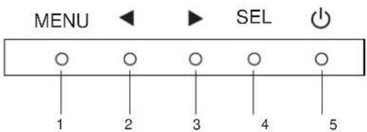
Control Function
1 Menu/Exit Display/exits the On Screen Display (OSD) menus.
21. Enter contrast of the OSD.
- Increase value of the adjustment item.
- Select item counter-clockwise.
3 1. Enter brightness adjustment.
- Decrease value of the adjustment item.
- Select item clockwise.
4 Select Selects the adjustment items from the OSD menus.
5 Power Switch Switches the power of the monitor.
Remote OSD Buttons(option)
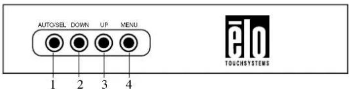
Control Function
1 Menu/Exit Display/exits the On Screen Display (OSD) menus.
21. Enter contrast of the OSD.
- Increase value of the adjustment item.
- Select item counter-clockwise.
3 1. Enter brightness adjustment.
- Decrease value of the adjustment item.
- Select item clockwise.
4 Select Selects the adjustment items from the OSD menus.
On Screen Display (OSD) Menu Functions
To Display and Select the OSD Functions:
1 Press the Menu key to activate the OSD menu.
2 Use ◀or ▶to move through the menu. Press the Select key, the parameter will be highlighted when selected.
3 To quit the OSD screen at any time during the operation, press the Menu key. If no keys are pressed for a short time period, the OSD automatically disappears.
NOTE: The OSD screen will disappear if no input activities are detected for 45 seconds.
Control Description
Contrast Increases or decreases contrast.
Brightness Increases or decreases brightness.
V-Position Moves the screen up or down.
H-Position Moves the screen left or right.
Recall Defaults Returns the monitor to its default settings.
RGB Press or to select 9300, 6500, 5500, 7500 and USER. Only when selecting USER can you make adjustments to the R/G/B content. Press Enter to restore to factory default setting.
Exit Exit the menu.
Sharpness Adjusts the sharpness.
Phase Increases or decreases the snow noise of the image after auto adjustment is made.
Clock The dot clock is fine-adjusted after auto adjust.
OSD H-Position Moves the OSD position horizontally on the screen. When the button is pressed, the OSD control menu will move to the right side of the screen. Likewise, when the ▶ button is pressed, the OSD control menu will move to the left side.
OSD V-Position Moves the OSD position vertically on the screen. When the button is pressed, the OSD control menu will move to the top side of the screen. Likewise, when the ▶ button is pressed, the OSD control menu will move to the lower side.
OSD Time Determines how long (in seconds) the OSD menu waits before closing automatically after no action has been performed.
Auto-Adjust Press Auto to enable this function. The Auto-Adjust will automatically adjust V-Position, H-Position, Clock and Clock-Phase.
OSD Language Select from English, French, German, Spanish, and Japanese.
Information Description Indicates the current resolution, H-Frequency and V-Frequency.
To reduce the need for adjustment for different modes, the monitor has default setting modes that are most commonly used as given in the table below. If any of these display modes are detected, the monitor automatically adjusts the picture size and centering. When no mode is matched, the user can store their preferred modes in the user modes. The monitor is capable of storing up to 7 user modes. The only condition to store as a user mode is the new display information must have 1 KHz difference for horizontal frequency or 1 Hz for vertical frequency or the sync signal polarities are different from the default modes.
H. Freq. Band Width
Mode Resolution (KHz) (MHz) H V
| 1 VGA 640 x 350 70 Hz 31.47 28.322 | |||||
| 2 VGA 720 x 400 70 Hz 31.47 28.322 | |||||
| 3 VGA 640 x 480 60 Hz 31.47 25.175 | |||||
| 4 MAC 640 x 480 66 Hz 35.00 32.24 - - | |||||
| 5 VESA 640 x 480 72 Hz 37.86 31.5 | - - | ||||
| 6 VESA 640 x 480 75 Hz 37.50 31.5 | - - | ||||
| 7 | VESA 800 x 600 56 Hz | 35.16 | 36 | + | + |
| 8 | VESA 800 x 600 60 Hz | 37.88 | 40 | + | + |
| 9 | VESA 800 x 600 75 Hz | 46.88 | 49.5 | + | + |
| 10 | VESA 800 x 600 72 Hz | 48.08 | 50 | + | + |
| 11 MAC 832 x 624 75 Hz 49.72 57.283 - - | |||||
| 12 | VESA 1024 x 768 60 Hz | 48.36 | 65 | - | - |
| 13 | SUN 1024 x 768 65 Hz | 52.45 | 70.49 | - | - |
| 14 | VESA 1024 x 768 70 Hz | 56.48 | 75 | - | - |
| 15 | VESA 1024 x 768 75 Hz | 60.02 | 78.75 | + | + |
| 16 | SXGA 1280 x 1024 60 Hz | 64 | 108 | + | + |
| 17 | SXGA 1280 x 1024 75 Hz | 80 | 135 | + | + |
| 18 | SXGA 1152 x 864 75 Hz | 67.5 | 108 | + | + |
| 19 | SXGA 1280 x 960 60 Hz | 60 | 108 | + | + |
The monitor is equipped with the power management function which automatically reduces the power consumption when not in use.
| Power |
| Mode Consumption |
| On <40W |
| Sleep <4W |
| Off <2W |
We recommend switching the monitor off when it is not in use for a long time.
NOTE: The monitor automatically goes through the Power Management System (PMS) steps when it is idle. To activate the monitor, press any key on the keyboard or move the mouse.
TROUBLESHOOTING
If you are experiencing trouble with your touchmonitor, refer to the following table. If the problem persists, please contact your local dealer or our service center.
Solutions to Common Problems
Problem Suggestion(s)
The monitor does not respond Check that the monitor's Power Switch is on.
after you turn on the system Turn off the power and check the monitor's power cord and signal cable for proper connection.
Characters on the screen are dim Refer to the About Touchmonitor Adjustments section to adjust the brightness.
The screen is blank During operation, the monitor screen may automatically turn
off as a result of the Power Saving feature. Press any key to see if the screen reappears.
Refer to the About Touchmonitor Adjustments section to adjust the brightness.
Screen flashes when initialized Turn the monitor off then turn it on again.
“Out of Range” display Check to see if the resolution of your computer is higher than that of the LCD display.
Reconfigure the resolution of your computer to make it less
than or equal to 1280 x 1024. See Appendix A for more information on resolution.
Touch doesn't work Make sure the touch cable is securely attached at both ends.
A
NATIVE RESOLUTION
The native resolution of a monitor is the resolution level at which the LCD panel is designed to perform best. For the LCD touchmonitor, the native resolution is 1280 x 1024 for the 17 inch size. In almost all cases, screen images look best when viewed at their native resolution. You can lower the resolution setting of a monitor but not increase it.
Input Video 17" LCD
640 x 480 (VGA) Transforms input format to 1280 x 1024
800 x 600 (SVGA) Transforms input format to 1280 x 1024
1024 x 768 (XGA) Transforms input format to 1280 x 1024
1280 x 1024(SXGA) Displays in Native Resolution
The native resolution of an LCD is the actual number of pixels horizontally in the LCD by the number of pixels vertically in the LCD. LCD resolution is usually represented by the following symbols:
| VGA 640 x | 480 |
| SVGA 800 x | 600 |
| XGA 1024 x | 768 |
| SXGA 1280 x | 1024 |
| UXGA 1600 x | 1200 |
As an example, a SXGA resolution LCD panel has 1280 pixels horizontally by 1024 pixels vertically. Input video is also represented by the same terms. SXGA input video has a format of 1280 pixels horizontally by 1024 pixels vertically. When the input pixels contained in the video input format match the native resolution of the panel, there is a one to one correspondence of mapping of input video pixels to LCD pixels. As an example, the pixel in column 45 and row 26 of the input video is in column 45 and row 26 of the LCD. For the case when the input video is at a lower resolution than the native resolution of the LCD, the direct correspondence between the video pixels and the LCD pixels is lost. The LCD controller can compute the correspondence between video pixels and LCD pixels using algorithms contained on its controller. The accuracy of the algorithms determines the fidelity of conversion of video pixels to LCD pixels. Poor fidelity conversion can result in artifacts in the LCD displayed image such as varying width characters.
B
TOUCHMONITOR SAFETY
This manual contains information that is important for the proper setup and maintenance of your touchmonitor. Before setting up and powering on your new touchmonitor, read through this manual, especially Chapter 2 (Installation), and Chapter 3 (Operation).
1 To reduce the risk of electric shock, follow all safety notices and never open the touchmonitor case.
2 Turn off the product before cleaning.
3 Your new touchmonitor is equipped with a 3-wire, grounding power cord. The power cord plug will only fit into a grounded outlet. Do not attempt to fit the plug into an outlet that has not been configured for this purpose. Do not use a damaged power cord. Use only the power cord that comes with your touchmonitor. Use of an unauthorized power cord may invalidate your warranty.
4 The slots located on the sides and top of the touchmonitor case are for ventilation. Do not block or insert anything inside the ventilation slots.
5 It is important that your touchmonitor remains dry. Do not pour liquid into or onto your touchmonitor. If your touchmonitor becomes wet do not attempt to repair it yourself.
The following tips will help keep your touchmonitor functioning at the optimal level.
• To avoid risk of electric shock, do not disassemble the brick supply or display unit cabinet. The unit is not user serviceable. Remember to unplug the display unit from the power outlet before cleaning.
- Do not use alcohol (methyl, ethyl or isopropyl) or any strong dissolvent. Do not use thinner or benzene, abrasive cleaners or compressed air.
• To clean the display unit cabinet, use a cloth lightly dampened with a mild detergent.
- Avoid getting liquids inside your touchmonitor. If liquid does get inside, have a qualified service technician check it before you power it on again.
- Do not wipe the screen with a cloth or sponge that could scratch the surface.
- To clean the touchscreen, use window or glass cleaner. Put the cleaner on the rag and wipe the touchscreen. Never apply the cleaner directly on the touchscreen.
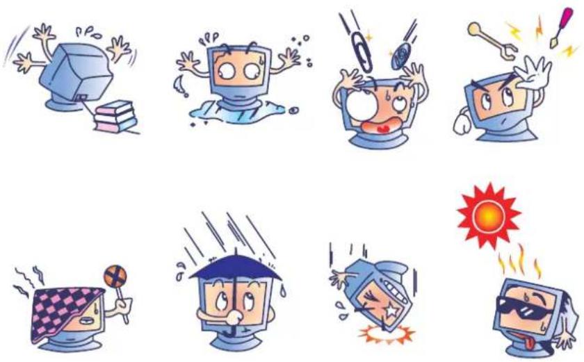
Warning

TECHNICAL SPECIFICATIONS
Model 1739L
LCD Display 17" TFT Active Matrix Panel
Display Size 338(H) x 270(V) mm
Pixel Pitch 0.264(H) x 0.264(V) mm
Display Mode VGA 640 x 350 (70Hz)
VGA 720 x 400 (70Hz)
VGA 640 x 480 (60 / 72/ 75Hz)
SVGA 800 x 600 (56 / 60 / 72 / 75Hz)
XGA 1024 x 768 (60 / 70 / 75Hz)
SXGA 1280 x 1024 (60 / 70 / 75Hz)
Max. Resolution SXGA 1280 x 1024 at 75Hz maximum
Contrast Ratio 1500:1 (typical)
Brightness No touchscreen: typical 257 cd/m
Surface Capacitive: typical 235 cd/m²; Min 201 cd/m²
SecureTouch: typical 257 cd/m² ; Min 220 cd/m²
AccuTouch: typical 224 cd/m²; Min 192 cd/m²
Response Time Tr: 15 ms Tf: 10ms (Typ.)
Display Color 16.7M
Viewing Angle Vertical -89
^0 \~+89 ^0
Horizontal -89° \~ +89°
Input Signal Video R.G.B. Analog 0.7Vp-p, 75 ohm
Sync
Signal Connector
Rear Controls
On Screen Display (OSD) Controls
Mini D-Sub 15 pin
Menu, ◀, ▶, Select, Power
Contrast, Brightness, H-Position, V-Position,
Color Temperature, Phase, Clock, OSD Time, Recall,
Language: English, French, German, Spanish, Japanese
Plug & Play
Touch Panel (optional)
DDC1 / 2B
IntelliTouch/CarrollTouch/Surface Capacitive/SecureTouch
AccuTouch
Power Adapter
Operating Conditions
Temperature
Humidity
0^ 40^ ( 32^ 104^ )
20% \~ 80% (No Condensation)
Altitude
To 12,000 Feet
Storage Conditions
Temperature
-20^ 60^ (-4^ 140^)
Humidity
10% \~ 90% (No Condensation)
Dimensions (HxWxD)
306 x 368 x 49mm
Weight (Net)
4.2Kg
IntelliTouch Touchscreen Specifications
Mechanical
Positional Accuracy Standard deviation of error is less than 0.080 in. (2.03 mm).
Equates to less than ±1%.
Touchpoint Density More than 100,000 touchpoints/in2 (15,500 touchpoints/cm2).
Touch Activation Force Typically less than 3 ounces (85 grams).
Surface Durability Surface durability is that of glass, Mohs' hardness rating of 7.
| Expected Life Performance | No known wear-out mechanism, as there are no layers, coatings, or moving parts. IntelliTouch technology has been operationally tested to more than 50 million touches in one location without failure, using a stylus similar to a finger. |
Sealing Unit is sealed to protect against splashed liquids, dirt, and dust.
Optical
Light Transmission (per ASTM 90%
D1003)
Visual Resolution All measurements made using USAF 1951 Resolution Chart,
under 30X magnification, with test unit located approximately 1.5 in (38 mm) from surface of resolution chart.
Clear surface: Excellent, with no noticeable degradation.
Antiglare surface: 6:1 minimum.
Gloss (per ASTM D2457
using a 60-degree gloss meter) Antiglare surface: Curved: 60 ± 20 gloss units or 75 ± 15 gloss
units.
Environmental
Chemical Resistance The active area of the touchscreen is resistant to all chemicals
that do not affect glass, such as:
Acetone
Toluene
Methyl ethyl ketone
Isopropyl alcohol
Methyl alcohol
Ethyl acetate
Ammonia-based glass cleaners
Gasoline
Kerosene
Vinegar
Electrostatic Protection (per Meets Levels 4 (15kV air/8 kV contact discharge)
CarrollTouch Infrared Touchscreen Specifications
MECHANICAL
Input Method Finger or gloved hand activation
ELECTRICAL
Positional Accuracy Typical centroid accuracy: 2 mm with 1 mm STD error
Resolution Touchpoint density is based on controller resolution of 4096 x 4096
Touch Activation Force No minimum touch activation force is required
Controller Board: Serial (RS232) or USB 1.1
Chip set: Serial (RS232) and USB 1.1
OPTICAL
Light Transmission Glass or acrylic overlay ≥ 90%
ENVIRONMENTAL
Temperature Operating: -20 ^ C to 70 ^ C
Storage: -40^ C to 85^ C
Relative Humidity Operating: 40 °C at 90% RH, noncondensing
Altitude Operating: 10,000 ft (3,048 m)
Storage/transport: 50,000 ft (15,240 m)
| Chemical Resistance | Glass overlay: The touch active area of the touchscreen is resistant to chemicals that do not affect glass, such as: acetone, toluene, methyl ethyl ketone, isopropyl alcohol, methyl alcohol, ethyl acetate, ammonia-based glass cleaners, gasoline, kerosene, and vinegar.Acrylic overlay: ASTM D1308 resistance to benzene, toluene, xylene, methylene chloride, acetone, ethyl acetate, and 40% sulfuric acid.Saturated cotton ball test: 30 minutes with gasoline, antifreeze, brake fluid, and diesel fuel with no damage.Polycarbonate bezel: Some sensitivity to hydrocarbons. |
Electrostatic Protection Per EN 61000-4-2, 1995: Meets Level 4 (15 kV air/8 kV contact discharges)
Agency Approvals UL, cUL, TUV, CE, FCC Class B
Sealability Can be sealed to meet NEMA 4 and 12 and IP65 standards
DURABILITY
Surface Durability Glass overlay: Surface durability is that of glass, Mohs' hardness rating of 7
Acrylic overlay: 9H or Mohs' hardness rating of 2.7
Surface Capacitive Touchscreen Specifications
MECHANICAL
Input method Finger
Glass Thickness 0.118" / 3.0 mm nominal. (Glass only, not including tape, wires and/or solder if used)
ELECTRICAL
Positional Accuracy Reported touch coordinates are within 1.5% of true position (based on viewing area dimensions)
Resolution Touchpoint density is based on controller resolution of 4096 x 4096
Controller Controller board size of 2.1" x 3.3" (5.4 x 8.4 cm), with auto-detect function for Serial (RS232) and USB 1.1 connection
OPTICAL Up to 85% per ASTM D1003
ENVIRONMENTAL
Temperature Touchscreen Operating: -15 ^ C to 70 ^ C
Storage: -50^ to 85^
Controller Operating: 0 °C to 65°C
Storage: -25^ to 85^
Relative Humidity Operating/Storage: 10% to 90% RH, noncondensing
Chemical Resistance Water, ammonia, isopropyl alcohol, and similar non-abrasive cleaners
Agency Approvals UL, cUL, TUV, CE, FCC Class A & B, CISPR B
Sealability Can be sealed to meet NEMA 4 and 12 and IP 65 standards
DURABILITY
Surface Durability Anti-glare hardcoat cannot be scratched using any stylus with Mohs rating equal to or less than 6. Tested in the laboratory to withstand over 160 million (mechanically simulated) touches without noticeable degradation.
SecureTouch Touchscreen Specifications
MECHANICAL
Input Method Finger or gloved hand (cloth, leather, or rubber) activation
ELECTRICAL
Positional Accuracy Standard deviation of error is less than 0.080 in. (2 mm)
Resolution Touchpoint density is based on controller resolution of 4096 x 4096, plus 255 levels corresponding to touch pressure
Touch Activation Force Typically 2 to 3 ounces (55 to 85 grams)
Controller Board: Serial (RS232) or USB 1.1
OPTICAL
Light Transmission Up to 90% per ASTM D1003-92
ENVIRONMENTAL
Temperature Operating: -20
^o C to 50^o C
Storage: -40^ C to 71^ C
Relative Humidity Operating: 40
^ C at 90% RH, noncondensing
Altitude Operating: 10,000 ft (3,048 m)
Storage/transport: 50,000 ft (15,240 m)
Chemical Resistance
The touch active area of the touchscreen is resistant to chemicals that do not affect glass, such as: acetone, toluene, methyl ethyl ketone, isopropyl alcohol, methyl alcohol, ethyl acetate, ammonia-based glass cleaners, gasoline, kerosene, vinegar
Electrostatic Protection
Per EN 6100-4-2, 1995: Meets Level 4 (15 kV air/8 kV contact discharges)
Agency Approvals UL, cUL, TUV, CE, FCC Class A
Sealability
Can be sealed to meet NEMA 3/3R/5/12/12K/13, IP64 standards
DURABILITY
Surface Durability
Surface durability is that of glass, Mohs' hardness rating of 7
Expected Life
No known wear-out mechanism, as there are no layers, coatings, or moving parts. SecureTouch technology has been operationally tested to more than 50 million touches in one location without failure, using a stylus similar to a finger.
Impact Resistance
Meets UL-60950 and CSA 22.2 No. 60950 ball drop test (0.5 kg, 50 mm diameter ball dropped from height of 1.3 m)
AccuTouch (resistive) Touchscreen Specifications
Mechanical
Positional Accuracy Standard deviation of error is less than 0.080 in. (2.03 mm).
Equates to less than ±1%.
Touchpoint Density More than 100,000 touchpoints/in
^2 (15,500 touchpoints/cm ^2 )
Touch Activation Force Typical less than 3 ounces(85 grams)
Surface Durability Surface durability is that of glass, Mohs' hardness rating of 7.
Expected Life Performance No known wear-out mechanism, as there are no layers,
coatings, or moving parts. IntelliTouch technology has been operationally tested to more than 50 million touches in one location without failure, using a stylus similar to a finger.
Scaling Unit is sealed to protect against splashed liquids, dirt, and dust.
Optical
Light Transmission (per ASTM 90%
D1003)
Visual Resolution All measurements made using USAF 1951 Resolution Chart,
under 30X magnification, with test unit located approximately 1.5 in (38 mm) from surface of resolution chart. Clear surface: Excellent, with no noticeable degradation. Antiglare surface: 6:1 minimum.
Gloss (per ASTM D2457 using Antiglare surface: Curved: 60 ± 20 gloss units or 75 ± 15 gloss a 60-degree gloss meter) units.
Environmental The active area of the touchscreen is resistant to all
Chemical Resistance
chemicals that do not affect glass, such as:
Acetone, Toluene, Methyl ethyl ketone, Isopropyl alcohol, Methyl alcohol, Ethyl acetate, Ammonia-based glass cleaners, Gasoline, Kerosene, Vinegar
Electrostatic Protection (per
Meets Level 4 (15 kV air/8 kV contact discharges).
REGULATORY INFORMATION
I. Electrical Safety Information:
A) Compliance is required with respect to the voltage, frequency, and current requirements indicated on the manufacturer's label. Connection to a different power source than those specified herein will likely result in improper operation, damage to the equipment or pose a fire hazard if the limitations are not followed.
B) There are no operator serviceable parts inside this equipment. There are hazardous voltages generated by this equipment which constitute a safety hazard. Service should be provided only by a qualified service technician.
C) This equipment is provided with a detachable power cord which has an integral safety ground wire intended for connection to a grounded safety outlet.
1) Do not substitute the cord with other than the provided approved type. Under no circumstances use an adapter plug to connect to a 2-wire outlet as this will defeat the continuity of the grounding wire.
2) The equipment requires the use of the ground wire as a part of the safety certification, modification or misuse can provide a shock hazard that can result in serious injury or death.
3) Contact a qualified electrician or the manufacturer if there are questions about the installation prior to connecting the equipment to mains power.
II. Emissions and Immunity Information
A) Notice to Users in the United States: This equipment has been tested and found to comply with the limits for a Class B digital device, pursuant to Part 15 of FCC Rules. These limits are designed to provide reasonable protection against harmful interference in a residential installation. This equipment generates, uses, and can radiate radio frequency energy, and if not installed and used in accordance with the instructions, may cause harmful interference to radio communications.
B) Notice to Users in Canada: This equipment complies with the Class B limits for radio noise emissions from digital apparatus as established by the Radio Interference Regulations of Industrie Canada.
C) Notice to Users in the European Union: Use only the provided power cords and interconnecting cabling provided with the equipment. Substitution of provided cords and cabling may compromise electrical safety or CE Mark Certification for emissions or immunity as
required by the following standards:
This Information Technology Equipment (ITE) is required to have a CE Mark on the manufacturer's label which means that the equipment has been tested to the following Directives and Standards: This equipment has been tested to the requirements for the CE Mark as required by EMC Directive 89/336/EEC indicated in European Standard EN 55022 Class B and the Low Voltage Directive 73/23/EEC as indicated in European Standard EN 60950.
D) General Information to all Users: This equipment generates, uses and can radiate radio frequency energy. If not installed and used according to this manual the equipment may cause interference with radio and television communications. There is, however, no guarantee that interference will not occur in any particular installation due to site-specific factors.
1) In order to meet emission and immunity requirements, the user must observe the following:
a) Use only the provided I/O cables to connect this digital device with any computer.
b) To ensure compliance, use only the provided manufacturer's approved line cord.
c) The user is cautioned that changes or modifications to the equipment not expressly approved by the party responsible for compliance could void the user's authority to operate the equipment.
2) If this equipment appears to cause interference with radio or television reception, or any other device:
a) Verify as an emission source by turning the equipment off and on.
b) If you determine that this equipment is causing the interference, try to correct the interference by using one or more of the following measures:
i) Move the digital device away from the affected receiver.
ii) Reposition (turn) the digital device with respect to the affected receiver.
iii) Reorient the affected receiver's antenna.
iv) Plug the digital device into a different AC outlet so the digital device and the receiver are on different branch circuits.
v) Disconnect and remove any I/O cables that the digital device does not use.
(Unterminated I/O cables are a potential source of high RF emission levels.)
vi) Plug the digital device into only a grounded outlet receptacle. Do not use AC adapter plugs. (Removing or cutting the line cord ground may increase RF emission levels and may also present a lethal shock hazard to the user.)
If you need additional help, consult your dealer, manufacturer, or an experienced radio or television technician.




MPR II

FCC Tested To Comply With FCC Standards FOR HOME OR OFFICE USE
WARRANTY
Except as otherwise stated herein or in an order acknowledgment delivered to Buyer, Seller warrants to Buyer that the Product shall be free of defects in materials and workmanship. The warranty for the touchmonitors and components of the product is regional; please contact your regional office.
Seller makes no warranty regarding the model life of components. Seller's suppliers may at any time and from time to time make changes in the components delivered as Products or components.
Buyer shall notify Seller in writing promptly (and in no case later than thirty (30) days after discovery) of the failure of any Product to conform to the warranty set forth above; shall describe in commercially reasonable detail in such notice the symptoms associated with such failure; and shall provide to Seller the opportunity to inspect such Products as installed, if possible. The notice must be received by Seller during the Warranty Period for such product, unless otherwise directed in writing by the Seller. Within thirty (30) days after submitting such notice, Buyer shall package the allegedly defective Product in its original shipping carton(s) or a functional equivalent and shall ship to Seller at Buyer's expense and risk.
Within a reasonable time after receipt of the allegedly defective Product and verification by Seller that the Product fails to meet the warranty set forth above, Seller shall correct such failure by, at Seller's options, either (i) modifying or repairing the Product or (ii) replacing the Product. Such modification, repair, or replacement and the return shipment of the Product with minimum insurance to Buyer shall be at Seller's expense. Buyer shall bear the risk of loss or damage in transit, and may insure the Product. Buyer shall reimburse Seller for transportation cost incurred for Product returned but not found by Seller to be defective. Modification or repair, of Products may, at Seller's option, take place either at Seller's facilities or at Buyer's premises. If Seller is unable to modify, repair, or replace a Product to conform to the warranty set forth above, then Seller shall, at Seller's option, either refund to Buyer or credit to Buyer's account the purchase price of the Product less depreciation calculated on a straight-line basis over Seller's stated Warranty Period.
THESE REMEDIES SHALL BE THE BUYER'S EXCLUSIVE REMEDIES FOR BREACH OF WARRANTY. EXCEPTFOR THE EXPRESS WARRANTY SETFORTHABOVE, SELLERGRANTS NO OTHER WARRANTIES, EXPRESS OR IMPLIED BY STATUTE OR OTHERWISE, REGARDING THE PRODUCTS, THEIR FITNESS FOR ANY PURPOSE, THEIR QUALITY, THEIR MERCHANTABILITY, THEIR NONINFRINGEMENT, OR OTHERWISE. NO EMPLOYEE OF SELLER OR ANY OTHER PARTY IS AUTHORIZED TO MAKE ANY WARRANTY FOR THE GOODS OTHER THAN THE WARRANTY SETFORTH HEREIN. SELLER'S LIABILITY UNDER THE WARRANTY SHALL BE LIMITED TO A REFUND OF THE PURCHASE PRICE OF THE PRODUCT. IN NO EVENT SHALL SELLER BE LIABLE FOR THE COST OF PROCUREMENT OR INSTALLATION OF SUBSTITUTE GOODS BY BUYER OR FOR ANY SPECIAL, CONSEQUENTIAL, INDIRECT, OR INCIDENTAL DAMAGES.
Buyer assumes the risk and agrees to indemnify Seller against and hold Seller harmless from all liability relating to (i) assessing the suitability for Buyer's intended use of the Products and of any system design or drawing and (ii) determining the compliance of Buyer's use of the Products with applicable laws, regulations, codes, and standards. Buyer retains and accepts full responsibility for all warranty and other claims relating to or arising from Buyer's products, which include or incorporate Products or components manufactured or supplied by Seller. Buyer is solely responsible for any and all representations and warranties regarding the Products made or authorized by Buyer. Buyer will indemnify Seller and hold Seller harmless from any liability, claims, loss, cost, or expenses (including reasonable attorney's fees) attributable to Buyer's products or representations or warranties concerning same.
INDEX
Numerics
17" LCD Touchmonitor (ET1739L-XCWA-X-G)
Dimensions, 36
A
About the Product, 8
About Touchmonitor Adjustments, 17
AccuTouch Touchscreen Specifications, 35
B
Brightness, 30
C
CarrollTouch Touchscreen specifications, 32
Care and Handling of Your Touchmonitor, 28
Certifications, 30
Cleaning Your Touchmonitor, 28
Contrast Ratio, 30
Controls and Adjustment, 19
D
Dimensions (HxWxD), 30
Display Color, 30
Display Mode, 30
Display Size, 30
E
Electrical Safety Information, 33
Emissions and Immunity Information, 33
|
Image problem, 23
Image, scrolling, 23
Input Signal, 30
Installation and Setup, 9
Installing the Driver Software, 12
Installing the Serial Touch Driver, 13
Installing the Serial Touch Driver for MS-DOS and Windows 3.1, 14
Installing the Serial Touch Driver for Windows XP, Windows 2000, Me, 95/98 and NT 4.0, 13
Installing the USB Touch Driver, 15
Installing the USB Touch Driver for Windows XP, Windows 2000, Me, 95/98 and NT 4.0, 15
IntelliTouch Touchscreen Specification, 31
M
Main Unit, 10
Max. Resolution, 30
N
Native Resolution, 25
O
Operating Conditions, 30
On Screen Display (OSD), 30
OSD Control Options, 20
OSD Menu Functions, 19
P
Pixel Pitch, 30
Plug & Play, 30
Power Adapter, 30
Power Management System, 22
Precautions, 7
Product Description, 7
Product Overview, 10
R
Rear Control, 30
Rear View, 10
Rear Panel Controls, 18
Regulatory Information, 33
Remote OSD Buttons(option), 18
Response Time, 30
S
SecureTouch Touchscreen Specifications, 34
Signal Connector, 30
Solutions to Common Problems, 23
Storage Conditions, 30
Surface Capacitive Touchscreen Specifications, 35
SVGA, 25
SXGA, 25
T
Technical Specifications, 29
Touch Interface Connection, 11
Touch not working, 23
Touch Panel (optional), 30
Touchmonitor Safety, 27
Touchmonitor Specifications, 30
Troubleshooting, 23
U
Unpacking Your Touchmonitor, 9
UXGA, 25
V
VGA, 25
Viewing Angle, 30
W
Warning, 28
Warranty, 41
Weight (Net), 30
X
XGA, 25
Get the latest...
• Product information
- Specifications
• News on upcoming events
- Press release
- Software drivers
Getting in Touch with Elo
To find out more about Elo's extensive range of touch solutions, visit our Web site at www.elotouch.com or simply call the office nearest you:
North American Europe Belgium Asia-Pacific
| Elo TouchSystems, Inc. | Elo TouchSystems GmbH & Co. KG | Elo TouchSystems | Touch Panel Systems K.K |
| 301 Constitution Drive, | Haidgraben 6 | Diestsesteenweg 692 | Sun Homada Bldg. 2F |
| Menlo Park, CA 94025 | D-85521 Ottobrunn | B-3010 Kessel-Lo | 1-19-20 Shin-Yokohama |
| USA Germany Belgium Kanagawa 222-0033 | |||
(800) ELO-TOUCH(800-356-8682)
| Tel 650-361-4700 | Tel +49(89)60822-0 | Tel +32(16)35-2100 | Tel +81(45)478-2161 |
| Fax 650-361-4747 | Fax +49(89)60822-150 | Fax +32(16)35-2101 | Fax +81(45)478-2180 |
| eloinfo@elotouch.com | elosales@elotouch.com | elosales@elotouch.com | www.tps.co.jp |
- Touchmonitor User Guide
- User Guide
- 17" LCD REAR-MOUNT TOUCHMONITOR
- 1739L Family 3000 Series
- Copyright © 2007 Tyco Electronics. All Rights Reserved.
- Disclaimer
- Trademark Acknowledgments
- Table of Contents
- Chapter 1
- Introduction 7
- Chapter 2
- Installation and Setup 9
- Chapter 3
- Operation 17
- Chapter 4
- Troubleshooting 23
- Appendix A
- Appendix B
- Appendix C
- Regulatory Information 37
- Warranty 39
- 1
- INTRODUCTION
- Product Description
- Precautions
- 2
- INSTALLATION AND SETUP
- Unpacking Your Touchmonitor
- Installing the Serial Touch Driver for Windows XP, Windows 2000, Me, 95/98 and NT 4.0
- Installing the Serial Touch Driver for MS-DOS and Windows 3.1
- Installing the USB Touch Driver for Windows XP, Windows 2000, Me, 95/98 and NT 4.0
- 3
- OPERATION
- About Touchmonitor Adjustments
- Control Function
- Remote OSD Buttons(option)
- On Screen Display (OSD) Menu Functions
- Control Description
- TROUBLESHOOTING
- Solutions to Common Problems
- Problem Suggestion(s)
- A
- NATIVE RESOLUTION
- Input Video 17" LCD
- B
- TOUCHMONITOR SAFETY
- Warning
- TECHNICAL SPECIFICATIONS
- Model 1739L
- IntelliTouch Touchscreen Specifications
- Mechanical
- Optical
- D1003)
- Gloss (per ASTM D2457
- Environmental
- CarrollTouch Infrared Touchscreen Specifications
- ELECTRICAL
- DURABILITY
- Surface Capacitive Touchscreen Specifications
- SecureTouch Touchscreen Specifications
- AccuTouch (resistive) Touchscreen Specifications
- Environmental The active area of the touchscreen is resistant to all
- REGULATORY INFORMATION
- Electrical Safety Information:
- Emissions and Immunity Information
- WARRANTY
- INDEX
- Numerics
- C
- D
- E
- |
- M
- N
- O
- P
- R
- S
- T
- U
- V
- W
- X
- Get the latest...
- Getting in Touch with Elo
Brand : ELO
Model : 1739L
Category : Screen