I-Series E541994 - Screen ELO - Free user manual and instructions
Find the device manual for free I-Series E541994 ELO in PDF.


| Product Type | Touchscreen Monitor |
| Model | I-Series E541994 |
| Brand | Elo |
| Screen Size | 19 inches (estimated) |
| Touch Technology | Projected Capacitive (PCAP) |
| Multi-Touch | 10-point touch |
| Resolution | 1280 x 1024 (SXGA) |
| Aspect Ratio | 5:4 |
| Brightness | 250 cd/m² |
| Contrast Ratio | 1000:1 |
| Viewing Angle | 178° / 178° |
| Dimensions (W x H x D) | 450 mm x 300 mm x 50 mm (estimated) |
| Weight | 5 kg (estimated) |
| Power Input | 100-240 VAC, 50/60 Hz |
| Power Consumption | 30 W (typical) |
| Connectivity | VGA, DVI, DisplayPort, USB (touch) |
| Mounting | VESA 100 x 100 mm |
| Protective Glass | Anti-glare, chemically strengthened |
| Operating Temperature | 0°C to 40°C |
| Certifications | CE, FCC, RoHS, UL |
| Warranty | 3 years |
| Cleaning | Use soft, lint-free cloth with mild cleaner; avoid abrasives |
| Spare Parts | Contact Elo support or authorized resellers |
Frequently Asked Questions - I-Series E541994 ELO
User questions about I-Series E541994 ELO
0 question about this device. Answer the ones you know or ask your own.
Ask a new question about this device
Download the instructions for your Screen in PDF format for free! Find your manual I-Series E541994 - ELO and take your electronic device back in hand. On this page are published all the documents necessary for the use of your device. I-Series E541994 by ELO.
USER MANUAL I-Series E541994 ELO
natural_image
Three black-framed tablets displaying blue abstract wave patterns (no text or symbols visible)USER MANUAL
Elo Touch Solutions
ESY10i1 10.1" i-Series Android Interactive Signage
ESY15i1 15.6" i-Series Android Interactive Signage
ESY22i1 21.5" i-Series Android Interactive Signage
SW602242 Rev D
Copyright © 2016 Elo Touch Solutions, Inc. All Rights Reserved.
No part of this publication may be reproduced, transmitted, transcribed, stored in a retrieval system, or translated into any language or computer language, in any form or by any means, including, but not limited to, electronic, magnetic, optical, chemical, manual, or otherwise without prior written permission of Elo Touch Solutions, Inc.
Disclaimer
The information in this document is subject to change without notice. Elo Touch Solutions, Inc. and its Affiliates (collectively "Elo") makes no representations or warranties with respect to the contents herein, and specifically disclaims any implied warranties of merchantability or fitness for a particular purpose. Elo reserves the right to revise this publication and to make changes from time to time in the content hereof without obligation of Elo to notify any person of such revisions or changes.
Trademark Acknowledgments
AccuTouch, CarrollTouch, Elo, Elo (logo), Elo Touch, Elo Touch Solutions, Elo TouchSystems, IntelliTouch, iTouch, SecureTouch, TouchTools and VuPoint are trademarks of Elo and its Affiliates. Windows is a trademark of Microsoft Corporation. Android is a trademark of Google Corporation.
Table of Contents
Chapter 1 – Introduction......4
Chapter 2 – Unpacking....5
Chapter 3 – i-Series System Installation....6
Chapter 4 – Mounting....7
Chapter 5 – Operation....10
Chapter 6 – Technical Support....23
Chapter 7 – Safety & Maintenance....24
Chapter 8 – Regulatory Information ...... 27
Chapter 9 – Warranty Information ...... 30
Chapter 1: Introduction
Product Description
Your new i-Series Interactive Signage system combines Elo Touch Solutions reliable performance with the latest developments in touchscreen technology and display design. This combination of features creates a natural flow of information between a user and the i-Series system.
This i-Series system incorporates an active matrix thin-film-transistor, and LCD panel to provide superior display performance. Features that enhance this systems performance are Projected Capacitive (PCAP) touchscreen, Plug & Play compatibility, Micro-HDMI Out, LAN/Wifi, built-in speakers, and headphone output capability. A general purpose input/output header is available and Bluetooth 4.0 is supported. Also 3G/4G LTE (Micro SIM card holder) support.
* Wifi, Bluetooth and 3G/4G are not available on the No Wifi/BT SKU.
Follow all warnings, precautions and maintenance as recommended in this user manual to maximize the life of your unit and prevent risks to user safety. See Chapter 8 for more information on i-Series system safety.
This manual contains information that is important for the proper setup and maintenance of the i-Series. Before setting up and powering on your new system, read through this manual, especially the Installation, Mounting, and Operation chapters.
Chapter 2: Unpacking
Unpacking the i-Series Interactive Signage System
- Carefully cut through the top piece of tape to open the top flaps.
- Remove the top layer of the packaging pulp.
a. The accessory box and the covered monitor will now be visible. - Lift the accessory box out of the packaging box to provide access to the required cables.
- Remove the monitor from the box and set it down.
Chapter 3: i-Series System Installation
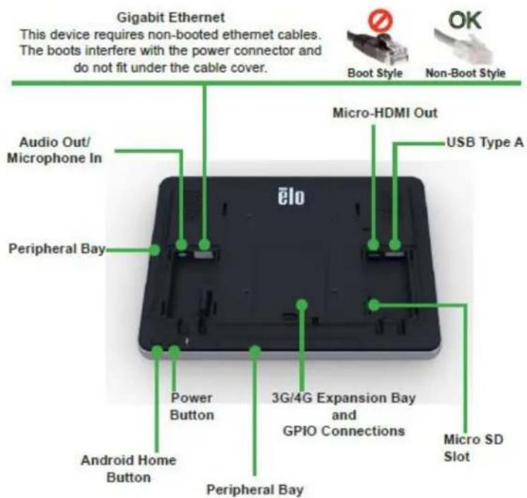
Connector Panel & Interfaces
Check that the following items are present and in good condition:
- i-Series system
- Quick Install Guide
- Power Brick
- Cables
- North America power cord
- Europe power cord
- Two (2) cable strain reliefs
- Two (2) screws
- Two (2) cable strain reliefs
- Two (2) screws
The connectors are accessed by removing the cable security covers from the rear of the i-Series system.
i-Series System Connections to an External Monitor
Connect a Micro-HDMI cable between the system and the monitor.
Chapter 4: Mounting
General Mounting Information
The monitor following the VESA pattern described in the following section.
For optimal touch performance, ensure that the monitor is supported fully and is as flat as possible.
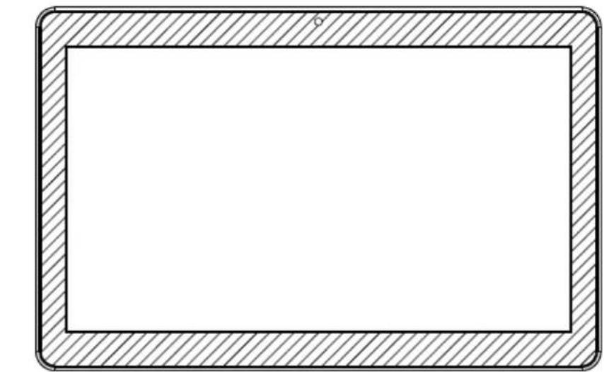
The following three mounting orientations are supported: Landscape, portrait and table top mode. For optimal touch performance, ensure that the monitor is supported fully and is as flat as possible.
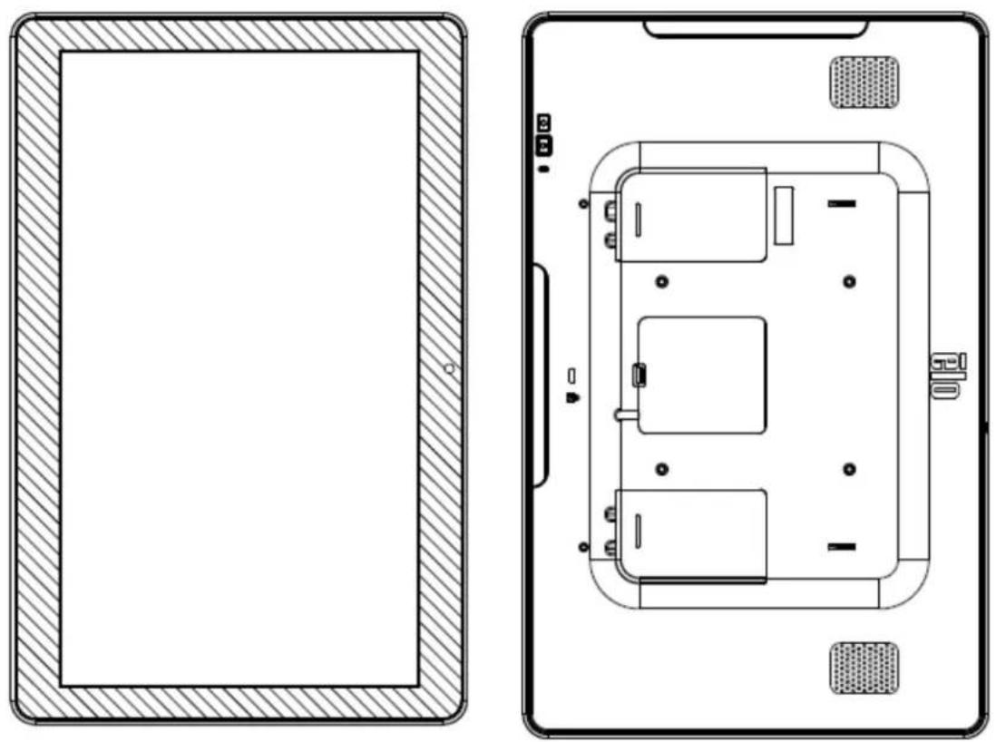
Portrait
natural_image
Blank rectangular frame with hatched border, no text or symbols presentLandscape

natural_image
Technical line drawing of a mechanical component or bracket (no text or symbols)Table Top
Rear VESA Mount
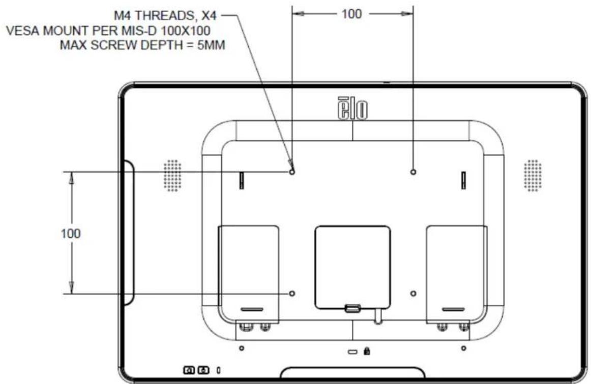
A four-hole 75x75mm (for 10.1") and 100x100 (for 15.6"/21.5") mounting pattern for M4 screws is provided on the rear of the monitor. The VESA FDMI-compliant counting is coded: VESA MIS-B, 75, C.
10.1"
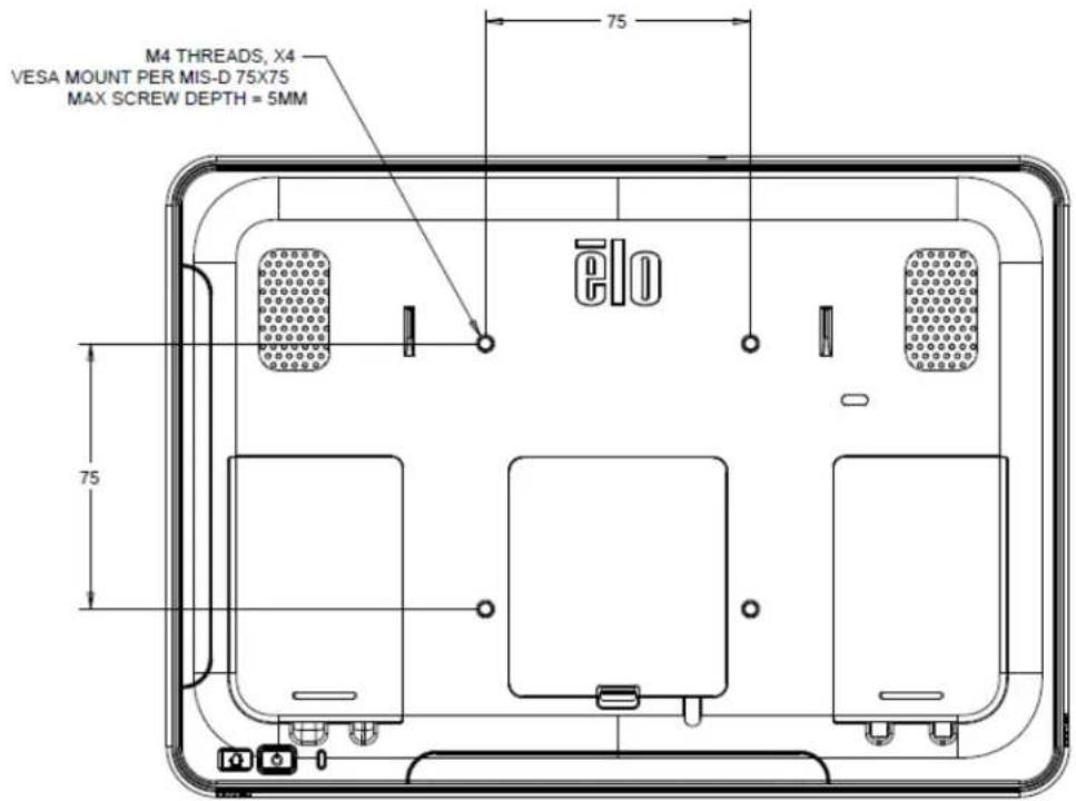
15.6" and 21.5"
Chapter 5: Operation
Power
To turn the system on, press the power button once. If a power cable is plugged in to the i-Series system, then the i-Series system will turn on automatically.
A Power Status LED is provided on the OSD Remote that functions according to the following table:
| i-Series System Status | Color | LED status |
| OFF | Orange | OFF |
| IDLE | White | BLINKING |
| ON | White | ON |
The system consumes low power when in IDLE and OFF modes. For detailed power consumption specifications, refer to technical specifications available on the Elo website www.elotouch.com.
Touching the screen will bring the system out of MONITOR IDLE mode.
If long periods of disuse are planned, unplug the AC power cable to save power.
The maximum voltage, frequency and current for the system are provided in the power ratings table below:
| Model | Operating Voltage Range | Operating Frequency Range | Operating Current Range |
| ESY10i1 | 100 - 240Vac | 50/60 Hz | 0.62A |
| ESY15i1 | 100 - 240Vac | 50/60 Hz | 0.72A |
| ESY22i1 | 100 - 240Vac | 50/60 Hz | 1.19A |
Operating System
Android version 4.4 will be pre-loaded on the system.
Projective Capacitance Touchscreens Technology
Four (4) simultaneous touches can be reported at one time for 10.1".
Ten (10) simultaneous touches can be reported at one time for 15.6" and 21.5".
Gesturing Images:
For multi-touch monitors, the following gestures are possible:
Dual Touch Gestures and their Functions:
Swipe – The action of moving a finger across the screen.
- The ability to swipe through from one picture to another or drag an icon
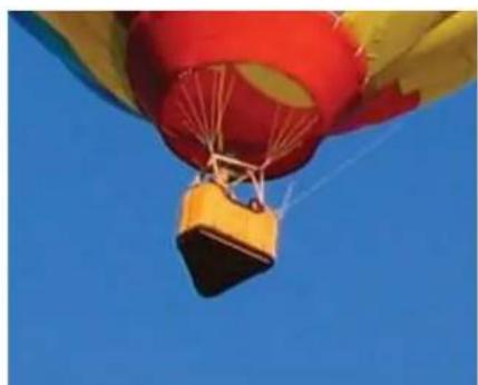
Pinch-Zoom – Zoom into a picture
- Place two fingers on the screen and move them closer together to zoom in. Move your fingers away from each other to zoom out.

natural_image
Three colorful hot air balloons floating against a clear blue sky (no text or symbols visible)Before zoom
natural_image
Hot air balloon with yellow and red colors against a clear blue sky (no text or symbols visible)After zoom
Video
An LCD panels native resolution is its width and height measured in number of pixels.
In almost all cases, an image displayed on an LCD monitor will look best when your image resolution matches the LCD panels native resolution.
10.1" is 1280x800, 15.6" is 1920x1080, 21.5" is 1920x1080.
Physical Button Functionality
| Parameter | Available Adjustment |
| Power Button | Turn on the system |
| Home Button | Returns to the Home page |
Audio
Earphone output with microphone input is supported.
3G/4G LTE module Information (Optional)
For the units that have 3G/4G LTE built in, the following are the supported bands:
• LTE (FDD) B1/B2/B3/B4/B5/B7/B8/B13/B17/B20
- Penta-band DC-HSPA+/HSPA+/HSPA/UMTS B1/B2/B4/B5/B8
• Quad-band EDGE/ GPRS/GSM 1900/1800/900/850 MHz
Data Transfer Rate:
• WCDMA PS: UL (384 kbps)/ DL (384 kbps)
• DC-HSPA+ :UL (11 Mbps)/ DL (42 Mbps)
- LTE FDD: UL (50 Mbps)/ DL (100 Mbps) @Bandwidth 20M (CAT3)
• GPRS/EDGE: Multi-slot Class 12
Support country list
• US
- Germany
Wifi + Bluetooth
The following protocols are supported for Wifi and Bluetooth:
- Bluetooth 4.0+EDR Class 2, A2DP/ HID (Keyboard/Mouse), SPP (printer), Barcode scanner (HID/SPP) support.
- IEEE 802.11b/g/n; WEP/WPA/WPA2 capable
Near Field Communication (NFC) Functionality (Optional)
The following NFC protocols are supported:
1.1.1 RS232 and USB2.0 interfaces by use of corresponding cables.
1.1.2 USB 2.0 compliant interface configurable to support USB HID: Keyboard, or USB Virtual COM.
1.1.3 RS232 data output baud rate up to 115.2K BPS
1.2 Payment Applications
1.2.1 American Express ExpressPay
1.2.2 Discover ZIP
1.2.3 MasterCard PayPass/MCHIP
1.2.4 Visa MSD/qVSDC
1.2.5 Google wallet
1.2.6 ISIS wallet
1.3 MIFARE Applications
1.3.1 Read/Write of MIFARE Plus/Classic/Ultralight/DESFire cards
1.3.2 Support MIFARE higher baud rate up to 424KHz
Barcode Scanner Functionality (Optional)
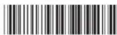
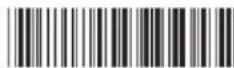
Incorporates proximity detector to activate Bar Code Scanner. Outstanding scanning performance up to 270 scans per second. Below are the supported Bar Code types and settings. Note: Telepen symbology only supports ASCII code.
Factory standard default settings
| Items | Default setting |
| Interface | HID USB |
| Language (Keyboard) | English |
| Reading mode | Presentation Mode |
| Terminator | CR |
| Code ID | Off |
| Accuracy | Read 1 time |
| Enable 1D symbologies | |
| UPC-A, UPC-E, EAN13, ENA8, CODE39, CODE93CODABAR, CODE128, MSI/Plessey, CODE32CODE11, TELEPEN, GS1 DataBar OmnidirectionalGS1 DataBar Limited, GS1 DataBar ExpandedInterleaved 2 of 5, Industrial 2 of 5, Matrix 2 of 5 | |
Check version

Symbologies setting
- Enable

* UPC-A on

* UPC-E on
* EAN13 on
* EAN8 on
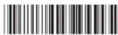
* Code39 on

*Codabar on

* Code93 on
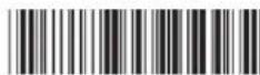
* Code128 on

* Interleaved 2of 5 on

* Industrial 2 of 5 on
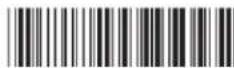
* Matrix 2 of 5 on
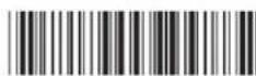
* MSI/Plessey on

* Code32 on
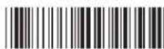
*Code11 on

* Telepen on

* GS1 DataBar Omnidirectional on

* GS1 DataBar Limited on

* GS1 DataBar Expanded on
- Disable
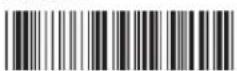
UPC-A off

UPC-E off
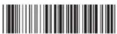
EAN13 off

EAN8 off
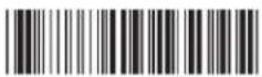
Code39 off

Codabar off

Code93 off

Code128 off

Interleaved 2of 5 off

Industrial 2 of 5 off

Matrix 2 of 5 off
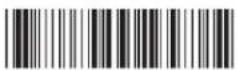
MSI/Plessey off
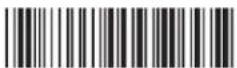
Code32 off

Code11 off

Telepen off

GS1 DataBar Omnidirectional off

GS1 DataBar Limited off

GS1 DataBar Expanded off
Magnetic Stripe Reader (MSR) Functionality (Optional)
The MSR shall operate in keyboard mode.
Capable of reading 3 tracks.
Security level and Encryption function: OFF
USB On The Go (OTG)
USB OTG is supported via the micro-USB connector located in the following position.
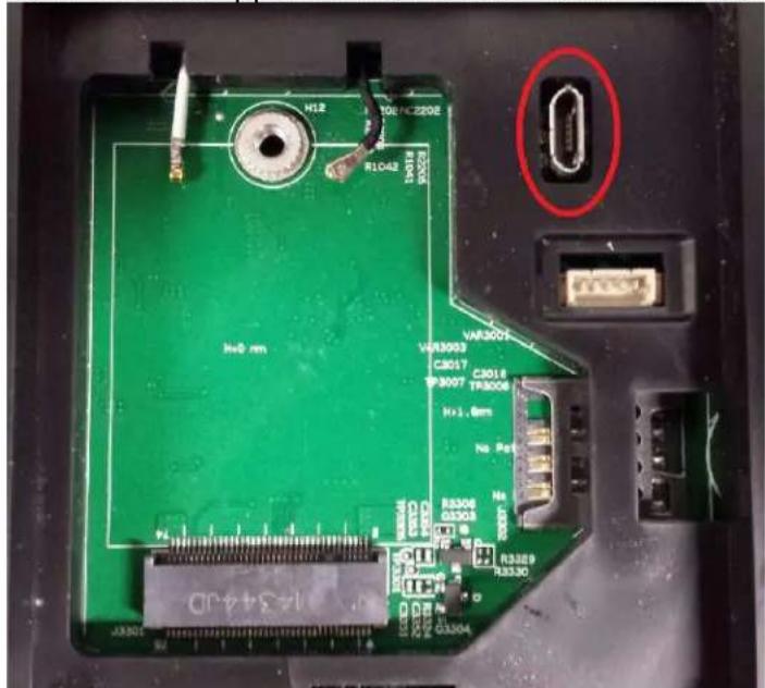
Note: Improper use of this connector can result in a broken connector.
HDMI Output
The HDMI(1920x1080P) output supports Elo monitor ET7001L/ET4201L/ET3201L/ET4243L/ET3243L.
General Purpose Input/Output (GPIO) Support
The i-Series supports a GPIO which can be used under the following conditions:
Max Voltage: 5V
Max Current: 200mA
There are two input connections and one output connection.
Pin 1→5 Volt output connection
Pin 2 → Input connection 1
Pin 3 → Input connection 2
Pin 4 and Pin 5 are tied to ground
Elo has a cable (PN # E086398) which extends this GPIO connection so that it is easy for users to connect their own peripherals. This cable can be found on the Elo website.
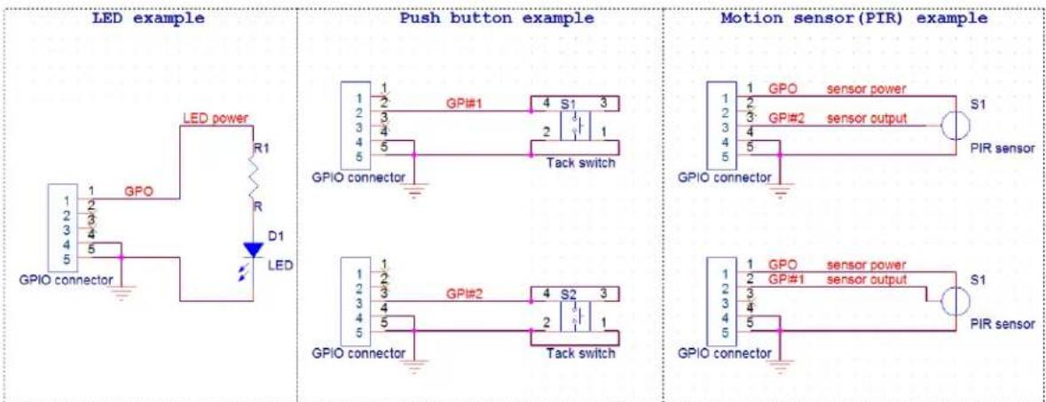
Example Circuit
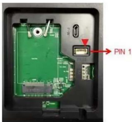
GPIO PIN1
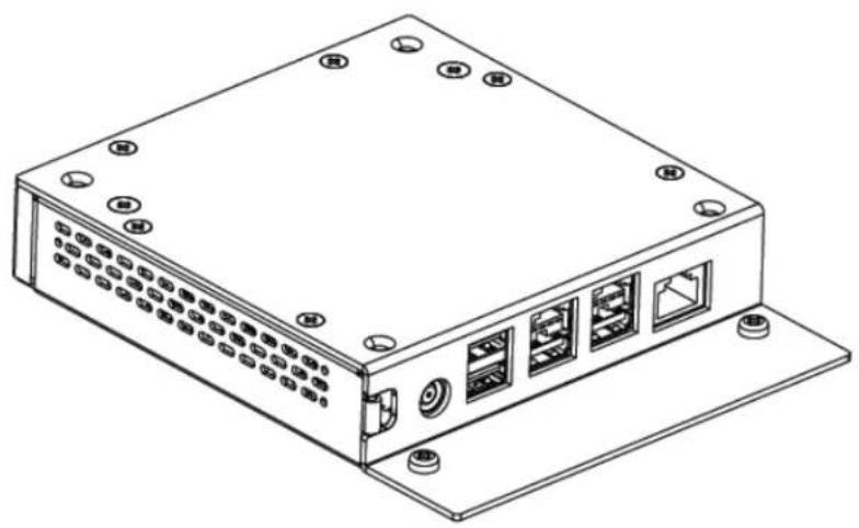
I-Series Expansion Module (Optional)
The I-Series Expansion Module is an accessory kit for the I-Series that allows for the additional ports:
- USB2.0 x2
- Powered USB x1 (1.5A) / 24V power
- Powered USB x1 (2.3A) /12V power
• RS232 x1(RJ45 to DB9 cable kit).
NOTE: The Expansion Module requires a 150W power adapter included in the kit, different from the standard I-Series 65W power adapter.
natural_image
Isometric line drawing of a rectangular electronic device with multiple ports and mounting holes (no text or symbols)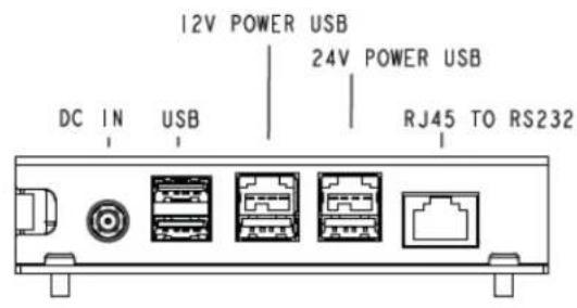
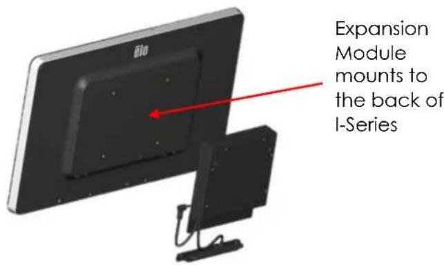
The I-Series Expansion Module has two part numbers and its configuration is listed below:
| Part Number | Configuration | Sizes Supported |
| E412240 | Expansion Module mounts to the back of I-Series | 15.6", 21.5" |
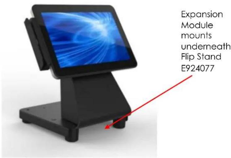
| E923781 | Expansion Module mounts to the bottom of flip stand E924077 | 10.1", 15.6" |
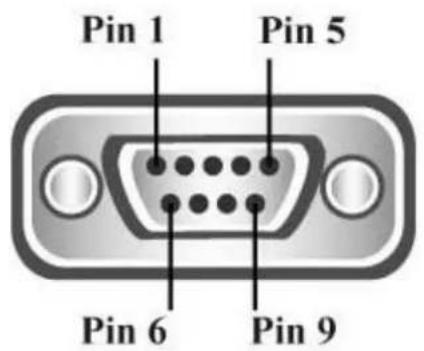
RS232 pin definition (DB-9 Male type)
| Pin 1 | NC |
| Pin 2 | RXD |
| Pin 3 | TXD |
| Pin 4 | DTR |
| Pin 5 | GND |
| Pin 6 | DSR |
| Pin 7 | RTS |
| Pin 8 | CTS |
| Pin 9 | NC |
Please visit FTDI website and download the Android SDK for software implementation. http://www.ftdichip.com/Support/SoftwareExamples/Android/J2xxHyperTerm.zip
Accessories included in the kit:
| Part Number | Kit Contents |
| E412240KIT,EXPANSION MODULE,ESY I-Series | E001060 AiO Power Brick,19V/150W,DELTAPower cable (1.8 m), IEC 60320-C5 to NA plugPower cable (1.8 m), IEC 60320-C5 to EU/KR plugRJ45-DB9 cableMounting screws onto I-Series (x4)USB cap and cable tie-down bracket with x2 screwsTIE-WRAP, 70-80mm x 2-3mmQIG |
| E923781KIT, EXP MODULELONG CABLE, I-SERIES | E001060 AiO Power Brick,19V/150W,DELTAPower cable (1.8 m), IEC 60320-C5 to NA plugPower cable (1.8 m), IEC 60320-C5 to EU/KR plugRJ45-DB9 cableScrews for flip-stand:Qty.2 - M4 x6 pan headQty.2 – M4 X 28 flat headQty.1 – M3 X 8 pan headQty.3 – tie-wrap, 2.5mm W X 70mm L min., color blackQIGCable Bracket |
1. Glossary
1.1. Abbreviation
- SoC: System on a chip
1.2. Terms
- IDLE_MODE: ELO specification for device interaction with POWER_KEY action
• MSR: Magnetic Stripe Reader
• BCR: Barcode Reader
• NFC: Near Field Communication - ELOPeripheralService: The fundamental class to provide different functions for ELO application developmentEx
2. System Overview
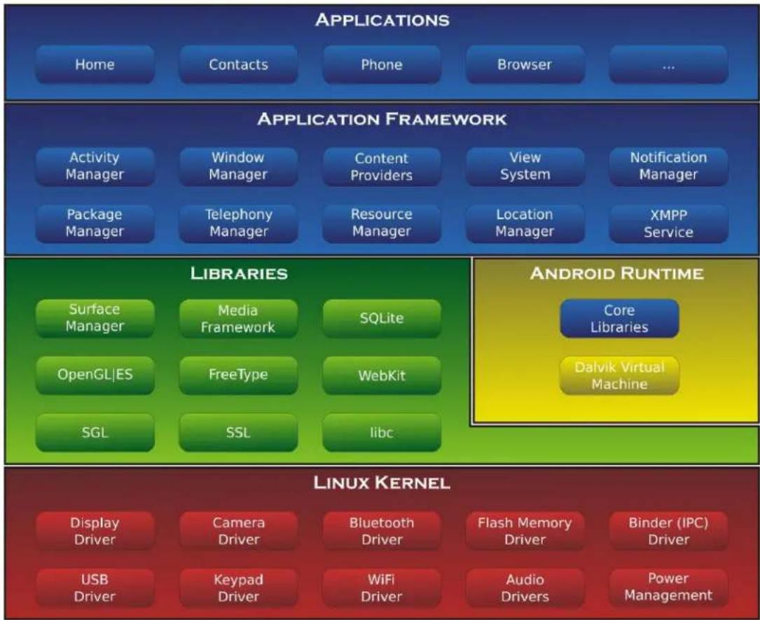
Fig 3-1 shows the software stack of Android system. This implementation based on Android design and extends the framework functionality at java services layer to fulfill customer requirement. The extended functionality at java service is named as “ELOPeripheralService” which provides the interfaces for application development.
flowchart
graph TD
    A["APPLICATIONS"] --> B["Home"]
    A --> C["Contacts"]
    A --> D["Phone"]
    A --> E["Browser"]
    A --> F["..."]

    G["APPLICATION FRAMEWORK"] --> H["Activity Manager"]
    G --> I["Window Manager"]
    G --> J["Content Providers"]
    G --> K["View System"]
    G --> L["Notification Manager"]
    G --> M["Package Manager"]
    G --> N["Telephony Manager"]
    G --> O["Resource Manager"]
    G --> P["Location Manager"]
    G --> Q["XMPP Service"]

    R["LIBRARIES"] --> S["Surface Manager"]
    R --> T["Media Framework"]
    R --> U["SQLite"]
    R --> V["OpenGL|ES"]
    R --> W["FreeType"]
    R --> X["WebKit"]
    R --> Y["SGL"]
    R --> Z["SSL"]
    R --> AA["libc"]

    AB["ANDROID RUNTIME"] --> AC["Core Libraries"]
    AB --> AD["Dalvik Virtual Machine"]

    AE["LINUX KERNEL"] --> AF["Display Driver"]
    AE --> AG["Camera Driver"]
    AE --> AH["Bluetooth Driver"]
    AE --> AI["Flash Memory Driver"]
    AE --> AJ["Binder (IPC) Driver"]
    AE --> AK["USB Driver"]
    AE --> AL["Keypad Driver"]
    AE --> AM["WiFi Driver"]
    AE --> AN["Audio Drivers"]
    AE --> AO["Power Management"]
Fig 2-1. Android System Structure
2.1. Android Framework Java Service
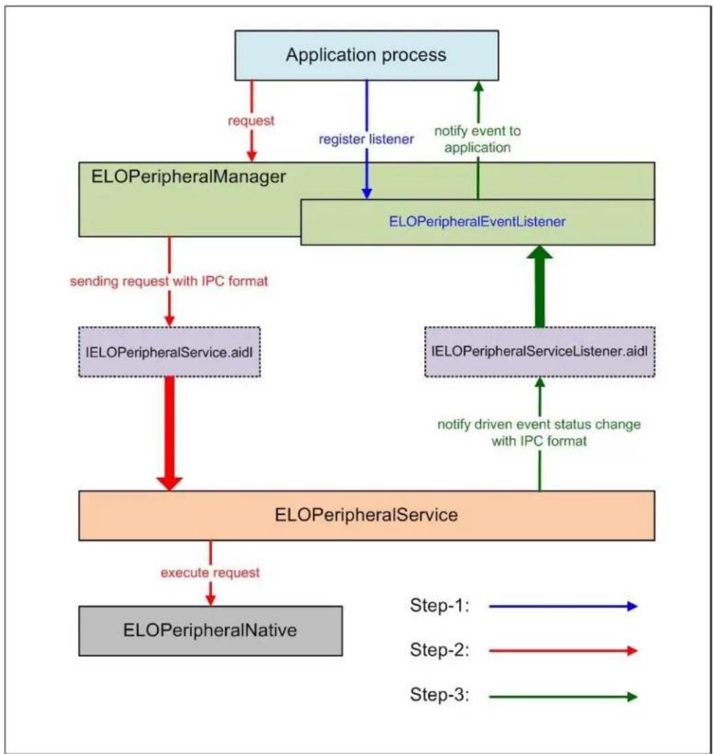
Based on developed programming language, Android services can be divided into native (C base) and java service. Android services are a kind of server-client structure where the server side can receive a request from the client and output the result to client. Also, the server-client structure can deal with synchronization issues from multi-client requests. Therefore, this framework ability, which forms the fundamental class “ELOPeripheralService,” is based on this kind of server-client design feature from Android.
2.2. ELOPeripheralService
ELOPeripheralService is the major module to act client request from application layer. In order to complete the Android framework system design for service then below classes is added into system:
- ELOPeripheralNative
■ Execution of some native-C function flows for ELOPeripheralService - ELOPeripheralManager
■ Provides the interface to the application layer, which is the client component relative to ELOPeripheralService
- EloPeripheralEventListener
■ Application extends abstract class to receive the driven event from EloPeripheralManager
■ Uses event driven notification method to notify the application program about the status change
- IELOPeripheralService.aidl
■ Android programming language for java layer IPC communication
■ Used for Client-Server (ELOPeripheralManager-ELOPeripheralService) IPC
communication where sending the application's request to server side
- IELOPeripheralServiceListener.aidl
■ Android programming language for java layer IPC communication
■ Used for server to notify the event driven status change to ELOPeripheralManager then ELOPeripheralManager will notify to application layer
flowchart
graph TD
    A["Application process"] -->|request| B["ELOPeripheralManager"]
    B -->|register listener| C["ELOPeripheralEventListener"]
    C -->|notify event to application| A
    B -->|sending request with IPC format| D["IELOPeripheralService.aidl"]
    C -->|notify driven event status change with IPC format| E["IELOPeripheralServiceListener.aidl"]
    D --> F["ELOPeripheralService"]
    E --> F
    F -->|execute request| G["ELOPeripheralNative"]
    style A fill:#e6f3ff,stroke:#333
    style B fill:#e6f3ff,stroke:#333
    style C fill:#e6f3ff,stroke:#333
    style D fill:#e6f3ff,stroke:#333
    style E fill:#e6f3ff,stroke:#333
    style F fill:#e6f3ff,stroke:#333
    style G fill:#e6f3ff,stroke:#333
Figure 2-2. ELOPeripheralService
3. ELOPeripheralManager and ELOPeripheralEventListener
As we mentioned at last section, ELOPeripheralManager and ELOPeripheralEventListener will be the component to provide interface for application development. Therefore, we provide the inner member data of ELOPeripheralManager and ELOPeripheralEventListener as below.
3.1. ELOPeripheralManager
Inside this manager contains some inner class member as below and for each inner class provides specific functionality to peripheral equipment or defined action flow.
| ELOPeripheralManager | public void registerListener(ELOPeripheralEventListener listener) | |
| public void unregisterListener(ELOPeripheralEventListener listener) | ||
| mBCR_APIs | ||
| mMSR_APIs | ||
| mNFC_APIs | ||
| mGPIO_APIs | ||
| mIDLE_APIs | ||
- public void registerListener(ELOPeripheralEventListener listener)
■ Provide interface for application to register the feedback structure instance
■ Needs to register before request (Activity life cycle: onResume) - public void unregisterListener(ELOPeripheralEventListener listener)
■ Provide interface for application to unregister the feedback structure instance
■ Needs to unregister before leave the application (Activity life cycle: onPause)
3.1.1. BCR
public class BCR {
    public boolean activeBCR() throws RemoteException {}
    public boolean disactiveBCR() throws RemoteException {}
    public boolean isBCRDeviceConnected() throws RemoteException {}
• activeBCR
3.1.2. GPIOs
public class GPIOs {
    public void pullHighGPIO(String iface) throws RemoteException {}
    public void pullLowGPIO(StringBalance) throws RemoteException {}
    public String[] getGPIOInterfaces() throws RemoteException {}
- pullHighGPIO
■ Pull high the state of GPIO-iface - PullLowGPIO
■ Pull low the state of GPIO-iface disactiveBCR - getGPIOInterfaces
■ Get the list string data of interest GPIOs at designed system.
■ Refer to Table 3-1 GPIOs list
Note:
■ The pull action only workable with output pin defined GPIO
■ The input pin defined GPIO can notify the application about the status change by "ELOPeripheralEventListener" also
| GPIOs | PIN define |
| gpio80 | Output |
| gpio81 | Input |
| gpio82 | Input |
Table 3-1 GPIOs List
3.1.3. IDLE
public class IDLE {
    public boolean activeIdleMode() {}
    public boolean disactiveIdleMode() {}
}
- activeldleMode
■ Force system to enter IDLE_MODE (IDLE_MODE on) - disactiveIdleMode
■ Force system to leave IDLE_MODE (IDLE_MODE off)
3.2. ELOPeripheralEventListener
public abstract class ELOPeripheralEventListener {
    /**
    * Active barcode scanner reading function by USB-ID-PIN
    */
    void onBCR_StateChange(int state, String data) {
    }
    void onGPIO_StateChange(int state, String data) {
    }
}
- onBCR_StateChange
■ Refer to Table 3-2
■ Notify the application about the BCR status change data - onGPIO_StateChange
■ Refer to Table 3-2
■ Notify the application about the GPIOs status change data
| BCR state | value |
| ELOPeripheralManager.BCR_STATE_DEVICE_CONNECTION | 1 << 0 |
| ELOPeripheralManager.BCR_STATE_DEVICE_DISCONNECTION | 1 << 1 |
| ELOPeripheralManager.BCR_STATE_DATA_RECEIVED | 1 << 2 |
| ELOPeripheralManager.BCR_STATE_PIN_AUTO_DISABLE | 1 << 3 |
| GPIO state | value |
| ELOPeripheralManager.GPIO_STATE_HIGH | 1 << 4 |
| ELOPeripheralManager.GPIO_STATE_LOW | 1 << 5 |
| GPIO data |
| gpio81 |
| gpio82 |
Table 3-2
Chapter 6: Technical Support
If you are experiencing trouble with your i-Series system, refer to the following suggestions. If the problem persists, please contact your local dealer or contact Elo Touch Solutions Customer Service.
Solutions to Common Problems
| Problem | Suggested Troubleshooting |
| The i-Series system does not respond when turning on the system. | Disconnect the AC power cable and verify that the i-Series system is properly installed. Reconnect the AC power cable. |
| Monitor display is blank. | If the Power Status LED is blinking, the monitor or i-Series system may be in SLEEP mode. Press any key / move the mouse / touch the touchscreen to see if the image reappears. |
To keep the system performing at an optimum level, follow the steps below:
Usage duty cycle:
18 hours on per 24 hours
Elo recommends using the Content Management System or O/S scheduling settings to manage duty cycle. This will enable power savings and trouble free operation throughout the life of the monitor.
Technical Assistance
Visit www.elotouch.com/go/websupport for online self-help.
Visit www.elotouch.com/go/contactsupport for technical support.
See this user manuals last page for worldwide technical support phone numbers.
For the latest version of this user manual, please visit to www.elotouch.com
Chapter 7: Safety & Maintenance
Safety
To avoid risk of electric shock, follow all safety notices and do not disassemble the i-Series system. They are not user-serviceable.
Do not block or insert anything inside any of the ventilation slots.
The i-Series system is equipped with a 3-wire, grounding power cord. The power cord plug only fits into a grounded outlet. Do not fit or modify the plug into an outlet that has not been configured for this purpose. Do not use a damaged power cord. Only use the power cord that came with your Elo i-Series system. Use of an unauthorized power cord may invalidate your warranty.
Ensure that the system is maintained and runs within the specified environmental conditions listed in the products specifications available on the Elo Touch Solutions website www.elotouch.com.
Environmental Conditions for Transportation and Storage
Temperature:
Portrait and Landscape Mode:
Operating
0^ C to 40^ C
Storage/Transportation
-20°C to 50°C
Humidity (non-condensing):
Operating
20% to 80%
Sto rage/Transportation
10% to 95%
Altitude:
Operating
0 to 3,658m
Storage/Transportation
0 to 12,192m
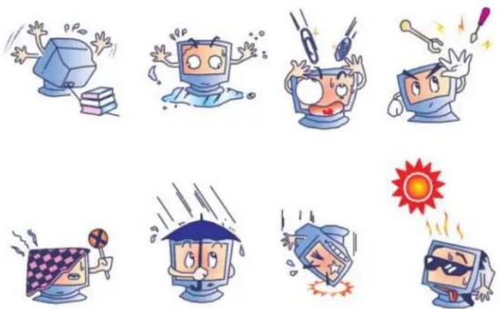
Caution
RISK OF EXPLOSION IF BATTERY IS REPLACED WITH AN INCORRECT TYPE. DISPOSE OF USED BATTERIES ACCORDING TO THE INSTRUCTIONS.
The following tips will help maintain optimal performance of the i-Series system:
- Disconnect the AC power cable before cleaning.
• To clean the display, use a cloth lightly dampened with a mild detergent. - It is important that your unit remains dry. Do not get liquid on or inside the unit. In the event that liquid does get inside, have a qualified service technician inspect the unit before you power it on again.
- Do not wipe the screen with a cloth or sponge that could scratch the surface.
- When cleaning the touchscreen, use window or glass cleaner applied to a clean cloth or sponge. Never apply the cleaner directly on the touchscreen. Do not use alcohol (methyl, ethyl or isopropyl), thinner, benzene, or other abrasive cleaners.
natural_image
Illustration of cartoon characters reacting to various stress or urgency effects, including computer, battery, and sun (no text or symbols)Waste Electrical & Electronic Equipment Directive (WEEE)
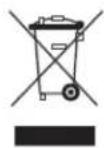
This product should not be disposed of with household waste. It should be deposited at a facility that enables recovery and recycling.
Elo has put in place recycling arrangements in certain parts of the world. For information on how you can access these arrangements, please visit http://www.elotouch.com/AboutElo/ewaste-program/.
Chapter 8: Regulatory Information
I. Electrical Safety Information:
Compliance is required with respect to the voltage, frequency, and current requirements indicated on the manufacturer's label. Connection to a different power source than those specified herein will likely result in improper operation, damage to the equipment or pose a fire hazard if the limitations are not followed.
There are no operator serviceable parts inside this equipment. There are hazardous voltages generated by this equipment which constitute a safety hazard. Service should be provided only by a qualified service technician.
Contact a qualified electrician or the manufacturer if there are questions about the installation prior to connecting the equipment to mains power.
II. Emissions and Immunity Information
Notice to Users in the United States: This equipment has been tested and found to comply with the limits for a Class A digital device, pursuant to part 15 of the FCC Rules. These limits are designed to provide reasonable protection against harmful interference when the equipment is operated in a commercial environment. This equipment generates, uses, and can radiate radio frequency energy and, if not installed and used in accordance with the instruction manual, may cause harmful interference to radio communications. Operation of this equipment in a residential area is likely to cause harmful interference in which case the user will be required to correct the interference at his own expense.
Notice to Users in Canada: This equipment complies with the Class A limits for radio noise emissions from digital apparatus as established by the Radio Interference Regulations of Industrial Canada. CAN ICES-3(A)/NMB-3(A)
This device complies with Industry Canada license-exempt RSS standard(s). Operation is subject to the following two conditions:
(1) this device may not cause interference, and
(2) this device must accept any interference, including interference that may cause undesired
operation of the device.
FCC RF Exposure Compliance: This equipment complies with radio frequency (RF) exposure limits adopted by the Federal Communications Commission for an uncontrolled environment. This equipment should be installed and operated with minimum distance 20 cm between the radiator & your body.
IC RF Exposure Compliance: This equipment complies with IC RSS-102 RF exposure limits set forth for an uncontrolled environment. This equipment should be installed and operated with minimum distance 20 cm between the radiator & your body.
Notice to Users in the European Union: Use only the provided power cords and interconnecting cabling provided with the equipment. Substitution of provided cords and cabling may compromise electrical safety or CE Mark Certification for emissions or immunity as required by the following standards:
CE RF Exposure Compliance: This device meets the EU requirements (1999/519/EC) and the International Commission on Non-Ionizing Radiation Protection (ICNIRP) on the limitation of exposure of the general public to electromagnetic fields by way of health protection.
General Information to all Users: This equipment should be installed and operated with minimum distance 20 cm between the radiator & your body.
This Information Technology Equipment (ITE) is required to have a CE Mark on the Manufacturer's label which means that the equipment has been tested to the following Directives and Standards: This equipment has been tested to the requirements for the CE Mark as required by EMC Directive 2004/108/EC as indicated in European Standard EN 55022 Class A and the Low Voltage Directive 2006/95/EC as indicated in European Standard EN 60950-1.
General Information to all Users: This equipment generates, uses and can radiate radio frequency energy. If not installed and used according to this manual the equipment may cause
interference with radio and television communications. There is, however, no guarantee that interference will not occur in any particular installation due to site-specific factors.
This device complies with part 15 of the FCC Rules. Operation is subject to the following two conditions: (1) This device may not cause harmful interference, and (2) this device must accept any interference received, including interference that may cause undesired operation.
1) In order to meet emission and immunity requirements, the user must observe the following:
a) Use only the provided I/O cables to connect this digital device with any computer.
b) To ensure compliance, use only the provided manufacturer's approved line cord.
c) The user is cautioned that changes or modifications to the equipment not expressly approved by the party responsible for compliance could void the user's authority to operate the equipment.
2) If this equipment appears to cause interference with radio or television reception, or any other device:
a) Verify as an emission source by turning the equipment off and on.
If you determine that this equipment is causing the interference, try to correct the interference by using one or more of the following measures:
i) Move the digital device away from the affected receiver.
ii) Reposition (turn) the digital device with respect to the affected receiver.
iii) Reorient the affected receiver's antenna.
iv) Plug the digital device into a different AC outlet so the digital device and the receiver are on different branch circuits.
v) Disconnect and remove any I/O cables that the digital device does not use. (Unterminated I/O cables are a potential source of high RF emission levels.)
vi) Plug the digital device into only a grounded outlet receptacle. Do not use AC adapter plugs. (Removing or cutting the line cord ground may increase RF emission levels and may also present a lethal shock hazard to the user.)
If you need additional help, consult your dealer, manufacturer, or an experienced radio or television technician.
III. Agency Certifications
The following certifications and marks have been issued or declared for this monitor:
• Standard SKU (with WiFi and Bluetooth):
United States FCC, UL
CB (International)
Canada cUL, IC
Europe CE
China CCC, SRRC
Russia EAC
Japan VCCI, MIC
Australia RCM
India BIS
- Cellular SKU:
United States FCC, UL CB (International) Europe CE United States PTCRB Europe GCF
- No WiFi/BT SKU:
United States FCC, UL CB (International) Canada cUL, IC Europe CE China CCC Russia EAC Japan VCCI Australia RCM Israel SII Kuwait KUCAS Saudi Arabia SASO South Korea KCC Taiwan BSMI Ukraine India BIS
IV. China RoHS
In accordance to Chinese law (Administration on the Control of Pollution Caused by Electronic Information Products), the section below lists out the name and amount of the toxic and/or hazardous materials that this product may contain.
| Component Name | Toxic or Hazardous Substances and Elements | |||||
| Lead(Pb) | Mercury(Hg) | Cadmium(Cd) | Hexavalent Chromium (Cr6+) | Polybrominated Biphenyls (PBB) | Polybrominated Diphenyl Ethers (PBDE) | |
| Plastic Parts | O | O | O | O | O | O |
| Metal Parts | X | O | O | O | O | O |
| Wire and Cable Assembly | X | O | O | O | O | O |
| LCD Panel | X | O | O | O | O | O |
| Touch Screen Panel | X | O | O | O | O | O |
| PCBA | X | O | O | O | O | O |
| Software (CD, etc.) | O | O | O | O | O | O |
O: Indicates that this toxic or hazardous substance contained in all of the homogeneous materials for this component is below the limit requirement in SJ/T11363-2006.
X: Indicates that this toxic or hazardous substance contained in at least one of the homogeneous materials use for this component is above the limit requirement in SJ/T11363-2006. For items marked with X, exemptions were taken according to EU RoHS.
Explanation of Markings
(1). In accordance with the SJ/T11364-2006 requirement, the electronic information products are marked with the following pollution control logo. The Environment-Friendly Use Period for this product is 10 years. The product will not leak or mutate under normal operating conditions listed below, so that the use of this electronic information product will not result in any severe environmental pollution, any bodily injury, or damage to any assets.
Operating Temperature:0-40 / Humidity:20%-80% (non-condensing).
Storage Temperature:-20\~60 / Humidity:10%\~90% (non-condensing).

(2). It is encouraged and recommended that this product be recycled and reused according to local laws. The product should not be thrown away casually.

Chapter 9: Warranty Information
For warranty information, go to http://www.elotouch.com/Support/warranty.asp
Get the latest...
• Product Information
- Specifications
- Upcoming events
- Press releases
- Software drivers
Getting in Touch with Us
To find out more about the extensive range of Elo touch solutions, visit our website at www.elotouch.com, or simply call the office nearest you:
| North America | Europe | Asia-Pacific | Latin America | |
| Elo Touch Solutions1033 McCarthy BlvdMilpitas, CA 95035 | Tel 800-ELO-TOUCHTel + 1 408 597 8000Fax +1 408 597 8001customerservice@elotouch.com | Tel +32 (0) 16 70 45 00 | Tel +86 (21) 3329 1385 | Tel 786-923-0251 |
| Fax +32 (0)16 70 45 49 | Fax +86 (21) 3329 1400 | Fax 305-931-0124 | ||
| elosales@elotouch.com | www.elotouch.com.cn/ | www.elotouch.com.ar | ||
Copyright 2016 Elo Touch Solutions, Inc. All rights reserved
- Elo Touch Solutions
- Copyright © 2016 Elo Touch Solutions, Inc. All Rights Reserved.
- Disclaimer
- Trademark Acknowledgments
- Table of Contents
- Chapter 1: Introduction
- Product Description
- Chapter 2: Unpacking
- Unpacking the i-Series Interactive Signage System
- Chapter 3: i-Series System Installation
- Connector Panel & Interfaces
- i-Series System Connections to an External Monitor
- Chapter 4: Mounting
- General Mounting Information
- Rear VESA Mount
- Chapter 5: Operation
- Power
- Operating System
- Projective Capacitance Touchscreens Technology
- Gesturing Images:
- Dual Touch Gestures and their Functions:
- Video
- Physical Button Functionality
- Audio
- 3G/4G LTE module Information (Optional)
- Wifi + Bluetooth
- Near Field Communication (NFC) Functionality (Optional)
- Barcode Scanner Functionality (Optional)
- Symbologies setting
- Magnetic Stripe Reader (MSR) Functionality (Optional)
- USB On The Go (OTG)
- HDMI Output
- General Purpose Input/Output (GPIO) Support
- I-Series Expansion Module (Optional)
- Glossary
- Abbreviation
- Terms
- System Overview
- Android Framework Java Service
- ELOPeripheralService
- ELOPeripheralManager and ELOPeripheralEventListener
- ELOPeripheralManager
- BCR
- GPIOs
- IDLE
- ELOPeripheralEventListener
- Chapter 6: Technical Support
- Technical Assistance
- Chapter 7: Safety & Maintenance
- Safety
- Environmental Conditions for Transportation and Storage
- Caution
- Waste Electrical & Electronic Equipment Directive (WEEE)
- Chapter 8: Regulatory Information
- Electrical Safety Information:
- Emissions and Immunity Information
- Agency Certifications
- China RoHS
- Explanation of Markings
- Chapter 9: Warranty Information
- Getting in Touch with Us
Brand : ELO
Model : I-Series E541994
Category : Screen