
502917 - Router Intellinet - Free user manual and instructions
Find the device manual for free 502917 Intellinet in PDF.


| Product Type | Wireless Router |
| Brand | Intellinet |
| Model | 502917 |
| Dimensions (approx.) | 200 x 150 x 30 mm |
| Weight (approx.) | 300 g |
| Power Supply | DC 12V, 1A |
| Wireless Standards | IEEE 802.11 b/g/n |
| Frequency Band | 2.4 GHz |
| Maximum Wireless Speed | 300 Mbps |
| WAN Port | 1 x 10/100 Mbps RJ45 |
| LAN Ports | 4 x 10/100 Mbps RJ45 |
| Antenna | 2 external antennas |
| Security Features | WEP, WPA, WPA2, SPI firewall |
| Maintenance | Clean with a dry, soft cloth; do not use liquid cleaners |
| Spare Parts | Not available separately; contact support for repairs |
| Operating Temperature | 0°C to 40°C |
| Storage Temperature | -20°C to 70°C |
Frequently Asked Questions - 502917 Intellinet
User questions about 502917 Intellinet
0 question about this device. Answer the ones you know or ask your own.
Ask a new question about this device
Download the instructions for your Router in PDF format for free! Find your manual 502917 - Intellinet and take your electronic device back in hand. On this page are published all the documents necessary for the use of your device. 502917 by Intellinet.
USER MANUAL 502917 Intellinet
PoE Web-Smart Switch
Model 502917
User's Manual
natural_image
Exterior view of a Siemens Intelluminet network switch device (no visible text or symbols on the device body)FCC Warning
This device has been tested and found to comply with limits for a Class A digital device, pursuant to Part 15 of the FCC Rules. These limits are designed to provide reasonable protection against harmful interference when the equipment is operated in a commercial environment. This equipment generates, uses and radiates radio frequency energy and, if not installed and used in accordance with the user's manual, may cause interference in which case user will be required to correct the interference at his own expense.
CE Mark Warning
This is a Class A product. In a domestic environment, this product may cause radio interference in which case the user many be required to take adequate measures.
Table Of Contents
Chapter 1 .... 1
Introduction 1
Key Features 2
Chapter 2 ....3
Package Contents .... 3
Chapter 3 ....4
Front Panel Layout 4
A. Function of 8 RJ-45 port 4
B. LED Indicators Of 8 Port 10/100Mbps Switch ....4
C. LED Definitions 4
- Power LED 4
• 10/100M LED ....4
- Link/ACT LED 4
- PD link....4
Real Panel Layout 5
A. AC Power Input 5
Chapter 4....6
Rack Mounting . 6
Chapter 5....7
Installation 7
A. How to connect the 502917 to PD device and Existing Switches 7
Chapter 6 8
Technical Specifications 8
Appendix ....
A. ANSI/TIA/EIA-568-A PLUG & Twisted-pair Cable .....9
B. EIA568A pin assignment ..... 9
C. Recommend CAT5 UTP specifications .....9
Chapter 1
8 Ports Power Over Ethernet Switch
Introduction
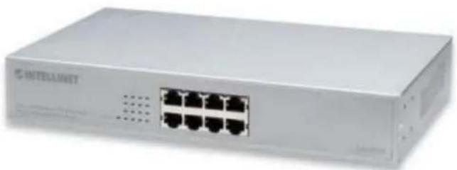
The 502917 is 8port Power Over Ethernet Switch consists 8 PSE/ Ethernet ports that is powered, detecting, classification capability, and programmable PD disconnect sensing, and with additional 8 10/100Mbps Ethernet port. That solves limitation of power outlet location offer system designer flexible solution to locate network device wherever.

natural_image
Exterior view of a white TATELLIMIT network switch device (no visible text or symbols on the device body)Key Features
- 10/100 auto-sensing ports — automatically detect optimal network speeds
- IEEE 802.3af-compliant RJ-45 PSE/PoE output ports
• Power output up to 15.4 Watts per port - All RJ-45 ports with Auto-MDIX (auto uplink) support
• Supports NWAY auto-negotiation
• Supports 8 VLAN groups, port-based and tagged VLAN support
• Supports Quality of Service (QoS), port-based and tagged with 2 priority levels
• Supports bandwidth control per port
• Supports MAC address locking per port - Broadcast storm control enable/disable
- Store and forward switching architecture
• Full/half duplex operation - IEEE 802.3x flow control for full duplex
- Zero packet loss back-pressure flow control for half duplex
- Packet filtering/forwarding rates: 148.800 pps (100 Mbps), 14.880 pps (10 Mbps)
• Supports 4096 MAC address entries
• 128 kBytes buffer memory - Desktop-size metal case
• LEDs for power, link/activity and PoE
Chapter 2
Package Contents
Before you start to install the Switch, please verify your package that contains the following items:
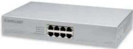
One 8 port Power Over Ethernet Switch
Rack-mount Kit For Rack Installation
One Power Cord
One User's Manual
natural_image
Exterior view of a network switch device (no visible text or labels)8 Port 10/100Mbps
Power Over Ethernet Switch

Power Cord

User's Manual

Note: If any of these items is found missing or damaged, please contact your local supplier for replacement.
Chapter 3
Front Panel Layout
A. Function of 8 RJ-45 Ports
There are 8 ports RJ-45 connectors on the front panel, and all ports has build IEEE802.3af PoE/PSE, is for the connecting with Powered Device (PD) device.

B. LED Indicators of 8 Port 10/100Mps Switch
| LED Color Status Description No. Of LED | ||||
| Power | Yellow | On | Power on | 1 |
| On Port | is linking to a PD device 8 (1~8) | PD Link Gr | ||
| Off No PD device link to the port 8 (1~8) | ||||
| On Port | is on the 100M status 8 (1~8) | 10/100M | ||
| Off Port | is on the 10M status 8 (1~8) | |||
| LINK/ACT. | Green | On | 10/100Mbps port for connection | 8 (1~8) |
| Flashing | 10/100Mbps for data activating | 8 (1~8) | ||
Green
C. LED Definitions
| Power LED | |
| On The unit is | powered on and ready for use. |
| Off The unit is | powered off. |
| PD link | |
| On Link to a PD | device, the port supply power output |
| Off No PD device | link, no power request from the device |
| 10/100M LED | |
| On The port is on the 100Mbps status. | |
| Off The port is on the 10Mbps status. | |
| LINK/ACT LED | |
| On The port is ready for 10/100Mbps connection. | |
| Flashing The data is transmitted or received on the port. | |
Rear Panel Layout
A. AC Power Input.
AC input (90-260V/AC, 50-60Hz) UL Safety.

Chapter 4
Rack Mounting
Optional Rack-mounting brackets are available to mount 502917 in standard EIA 19-inch rack. 502917 is supplied with two mounting brackets and eight screws. And please assemble according to the following steps.
First, put the 502917 on the flat surface. Locate the mounting brackets on the sides of the Switch with the mounting holes on each.
Next, insert the screw through the bracket and into the bracket mounting holes in the 502917. Then, place the Switch in to 19-inch rack.

natural_image
Technical line drawing of a mechanical or electronic assembly with multiple ports and mounting brackets (no text or symbols)Chapter 5
Installation
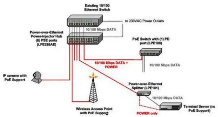
How to connect the 502917 to PD device and existing Switch
Power-over-Ethernet Switches
flowchart
graph TD
    A["Existing 10/100 Ethernet Switch"] -->|to 230VAC Power Outlets| B["Power-over-Ethernet Power-Injector Hub (8) PSE ports (LPE286AE)"]
    A --> C["PoE Switch with (1) PD port (LPE108)"]
    B --> D["IP camera with PoE Support"]
    C --> E["Power-over-Ethernet Splitter (LPE101)"]
    E --> F["Terminal Server (no PoE Support)"]
    F --> G["POWER only"]
    G --> H["Wireless Access Point with PoE Support"]
    H --> I["10/100 Mbps DATA + POWER"]
    I --> J["10/100 Mbps DATA"]
Connect straight-through twisted-pair cable (Cat. 5) from existing Switch to the input (Data) port of 502917, then connect the Output (Data+Power) port to the PD device, such as Wireless AP, Another switch with PD function...etc.
Chapter 6
Technical Specifications
Standards
• IEEE 802.3 (10Base-T Ethernet)
- IEEE 802.3u (100Base-TX Fast Ethernet)
- IEEE 802.3x (flow control, full duplex mode)
- IEEE 802.3af (Power over Ethernet)
General
• Media support:
- 10Base-T Cat3, 4, 5 UTP/STP RJ-45
- 100Base-TX Cat5 UTP/STP RJ-45
- Ports: 8 RJ-45 10/100 Mbps PoE ports
- Packet filter/forwarding rate:
- 148.800 pps (100 Mbps)
- 14.880 pps (10 Mbps)
- Configuration options:
- Port bandwidth control:
disable/128/256/512/1024/2048/4096/8192 kbps
- VLAN: port-based and tagged, up to 8 groups
- Quality of Service (QoS): 2 priority levels and port-based
ratio controlling the ratio between high and low priority
- Full and half duplex per port
- MAC address locking
• Certifications: FCC Class A, CE Mark
LEDs
- Power
- Link/activity for 10 and 100 Mbps
• PoE
Power
- Input: 90 to 260 V AC, 50 to 60 Hz
• Power consumption: 180 Watts (maximum)
Package Contents
- PoE Web-Smart Switch
- Power cable
- User manual
A. ANSI/TIA/EIA-568-A PLUG & Twisted-pair Cable
The IEE802.3u Standards permits the use of category 3, 4, 5 or better balanced cable pairs, installed according to ANSI/EIA-568-A. This appendix provides pinout and brief information for the CAT5 unshielded twisted pair cables
B. EIA568A pin assignment:
| Pin Number | Assignment |
| 1 | Plus data transmission (Pair 3) |
| 2 | Minus data transmission (Pair 3) |
| 3 | Plus data receiver (Pair 2) |
| 6 | Minus data receiver (Pair 2) |
| 4 | Not used by 10BASE-T and 100Base-TX (Data pair 1) |
| 5 | |
| 7 | Not used by 10BASE-T and 100Base-TX (Data Pair 4) |
| 8 |
C. Recommend CAT5 UTP specifications
Physical:
FR-PVC cable construction
Cable Type: 4-pair unshielded-twisted pair solid copper
Conductors: 24 AWG, solid bare annealed copper
Operating temperature: -20 ^ C to +75 ^ C
Electrical:
Impedance: 100 ±15 %
Near-End Cross-talk: 38dB @ 100 MHz
Attenuation: 22 dB/100 m typical @ 100 MHz
Maximum DC resistance : 9.38 / 100 m (24 AWG) at 20°C
■ Maximum DC insulation resistance 150M/km


- PoE Web-Smart Switch
- FCC Warning
- CE Mark Warning
- Table Of Contents
- Chapter 1
- Ports Power Over Ethernet Switch
- Introduction
- Key Features
- Chapter 2
- Package Contents
- Chapter 3
- Front Panel Layout
- Function of 8 RJ-45 Ports
- Rear Panel Layout
- AC Power Input.
- Chapter 4
- Rack Mounting
- Chapter 5
- Installation
- Chapter 6
- Technical Specifications
- Standards
- General
- LEDs
- Power
- ANSI/TIA/EIA-568-A PLUG & Twisted-pair Cable
- EIA568A pin assignment:
- Recommend CAT5 UTP specifications
- Physical:
- Electrical:
Brand : Intellinet
Model : 502917
Category : Router