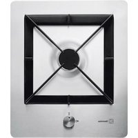
FPZ2OV - Cooker REX - Free user manual and instructions
Find the device manual for free FPZ2OV REX in PDF.


| Product Type | Gas Hob (Cooker Top) |
| Brand | Rex |
| Model | FPZ2OV |
| Number of Burners | 4 |
| Burner Types | Ultra-rapid (treble crown), Rapid, Semi-rapid, Auxiliary |
| Burner Power (Ultra-rapid) | 4.0 kW |
| Burner Power (Rapid) | 3.0 kW |
| Burner Power (Semi-rapid) | 2.0 kW |
| Burner Power (Auxiliary) | 1.0 kW |
| Total Power | 10.0 kW |
| Gas Connection | G 1/2" |
| Gas Types Supported | Natural Gas (Methane) 20 mbar, LPG (Butane/Propane) 28-30/37 mbar |
| Electrical Supply | 230 V ~ 50 Hz |
| Recess Dimensions (W x D) | 447 mm x 382 mm |
| Materials | Stainless steel hob, enameled parts, cast iron or stainless steel grids |
| Ignition | Automatic electric ignition via ceramic glow plug |
| Safety Features | Flame failure device (thermocouple), child safety warnings |
| Cleaning | Removable burner caps and crowns, wash with warm soapy water, avoid abrasives |
| Installation Requirements | Qualified personnel, proper ventilation, gas and electrical connection per local regulations |
| Weight (approx.) | 12 kg |
Frequently Asked Questions - FPZ2OV REX
User questions about FPZ2OV REX
0 question about this device. Answer the ones you know or ask your own.
Ask a new question about this device
Download the instructions for your Cooker in PDF format for free! Find your manual FPZ2OV - REX and take your electronic device back in hand. On this page are published all the documents necessary for the use of your device. FPZ2OV by REX.
USER MANUAL FPZ2OV REX
natural_image
Technical line drawing of a gas stove or heating unit with a central vent and cooling fan (no text or symbols)Fig.2

natural_image
Technical line drawing of a gas stove with cooling tower and side-mounted unit (no text or symbols)Fig.3
natural_image
Technical line drawing of a screwdriver tool fastening a mechanical component (no text or symbols)Fig.12
natural_image
Diagram of a mechanical valve assembly with a magnified view showing internal components (no text or symbols)Fig. 13
natural_image
Technical line drawing of a mechanical assembly with a central circular component and two cylindrical components (no text or symbols)
natural_image
Technical line drawing of a mechanical device with a central circular component and two protruding components (no text or symbols)Semirapido

natural_image
Technical line drawing of a mechanical assembly with a central circular component and mounting base (no text or symbols)
natural_image
Technical line drawing of a mechanical device with a central hub and base mount (no text or symbols)Tripla Corona

natural_image
Technical line drawing of a mechanical component with concentric rings and mounting brackets (no text or symbols)
natural_image
Technical line drawing of a mechanical component with concentric diamond-shaped frame and central hub (no text or symbols)natural_image
Technical line drawing of a mechanical assembly with a screwdriver inserted, showing no text or symbols.Fig.20

Fig.17
natural_image
Technical line drawings of four square-shaped components with internal features, shown from top and side views (no text or symbols)
From the Electrolux Group. The world's No.1 choice.
The Electrolux Group is the world's largest producer of powered appliances for kitchen, cleaning and outdoor use. More than 55 million Group products (such as refrigerators, cookers, washing machines, vacuum cleaners, chain sews and lawn mowers) are sold each year to a value of approx. USD 14 billion in more than 150 countries around the world.

For your safety
The use of this new appliance is east. Nevertheless it is important to read carefully this handbook before installing and using the appliance for the first time. In this way you can obtain the best performance, avoid wrong behaving, using the appliance in absolute safety and respect the environment.
Installation
The installation of the appliance and the connection to the electricity supply has to be carried out by QUALIFIED PERSONNEL ONLY. Before any intervention it is necessary to control the appliance is UNCONNECTED from the electricity supply..
Make sure the air can easily flow around the appliance. A bad ventilation produces an oxygen defeat.
Make sure the appliance is alimented by the type of gas indicated on the related adhesive label, in the closeness of the connection pipe of the gas supply..
The use of a gas cooker produces heat and humidity in the room where it is installed
Make sure there is a proper ventilation in the room, by maintaining opened and efficient the air intakes or by installing an extraction hood with a discharge conduct.
If you use intensively the appliance or for a prolonged time, you have to make the ventilation more efficient, for example by opening the window or by increasing the power of the electrical ventilator if available.
After having unpacked the appliance, make sure the product is not damaged and that the alimentation cable is in perfect conditions.
On the contrary. Please contact your retailed before installing the appliance.
The manufacturer declines any responsibility in case of not respecting the accident prevention rules.
Children safety
This appliance has to be used only by adults. Make sure children do not touch the controls or play with this appliance.
The exposed/external elements of this appliance get hot while cooking and remain hot for a certain period after blowing out. Keep children away from the equipment until when the equipment get cold.
While using
It is really important to keep this handbook with the equipment for any future consultation. If you sell or give the equipment to any other person, make sure you give to the new user this handbook in order to be informed on the correct working of the machine and related warnings.
This appliance is designed solely for household use for cooking food, inside private houses and not for professional purpose. Avoid to use this appliance for any other purpose. It may cause hazard to modify or try to modify the features of this product.
Keep properly cleaned the equipment. Food remaining may cause fire risks.
In case of faults do not try to repair personally the equipment. Repairs carried out by non competent personnel may cause damages or fire risks.
First of all consult the content of this handbook.
If you do not find the information you need, please contact the closest Assistance Centre.
The assistance to this appliance has to be carried out by the authorized Technical Assistance Centre. Please ask for original spare parts only.
After having used this appliance please make sure all controls are in "OFF" position.
If you use an electrical outlet near this equipment, be careful the cables the appliances you are using do not touch it and are enough far away from the warm parts of this equipment.

Suggestions for the environment protection.
All the materials used are compatible with the environment and recyclable. We be you to give your contribute for the environment conservation, using the proper waste disposals channels.
The unused appliances are not waste without value. Through the ecological disposal, different materials used for the production of Your appliance can be reclaimed.
Please take information on the actual possibilities for the ecological disposal by your specialized retailer, or through your local city office.
Before scrapping the appliance, cut the cable the supply cable in order to make it useless.
Guide to the instructions reading
These symbols will help you in finding quickly the most important information.

Safety information

"Step by step" instructions

Useful advices and suggestions

Information related to the environment protection

This appliance is in conformity with the following Directives CEE:
- 73/23 e 90/683 (related to the Low Voltage);
-89/336 (related to the Electromagnetic Compatibility); - 90/396 (related to the Gas working appliances)
- 93/68 (related to the General Directives and following modifications.
These instructions are only valid for the countries indicated by the symbols on the cover of the instruction handbook and the appliance.
Index
For the User
| For your safety 2 | |
| Use instructions | 3 |
| Cleaning and maintenance | 4 |
| Periodic maintenance | 4 |
| Assistance and spare parts | 5 |
| Guarantee conditions | 5 |
Use instructions

Before using the appliance, remove all the packing materials, advertising labels included and eventual protective film.
The control knobs of the cooker top
On the front side of the top you will see the knobs for the gas burners' running/working. The symbols indicated on the knobs have the following meaning:

Burners ignition

To obtain the flame easily, turn the burner on before putting saucepan on the grid.

Push the knob of the corresponding burner firmly and turn it in an anti-clockwise direction until the symbol of "maximum gas supply". The flame lights up automatically.
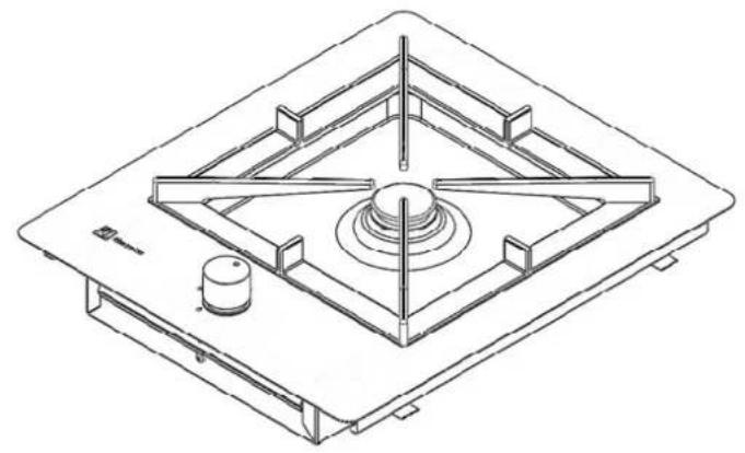
Once the burner is on, keep the knob press for about 5 seconds; This time in necessary to the thermocouple to warm up. (picture 1, letter D) and deactivate the safety valve which otherwise would shut off the gas flow.
At this point, control the flame is regular and turn the knob up to the requested intensity.
If after some attempts the flame does not light up, control that the "grid cap" (indicated in picture 1 with letter A) and the "crown" (letter B) are on the right position.
To shut of the flame, turn the knob in a clockwise direction until the symbol.
For the installer
| Technical features | 5 |
| Installer instructions | 6 |
| Connection to the gas supply | 7 |
| Connection to the electricity supply | 8-9 |
| Adjustment to the different types of gas | 10-11 |
| Recess on modular furniture | 12-13-14-15 |

For a correct use of the burners.
For a less gas consume and a better performance, use only flat-bottomed pots and pans which fit the burners, see below table.
| Burner | Pot diameter minimum | Pot diameter maximum |
| Ultra-rapid (treble crown) | 160 mm. | 260 mm. |
| Rapid (rapid) | 160 mm. | 240 mm. |
| Medium (semi-rapid) | 120 mm. | 220 mm. |
| Small (auxiliary) | 80 mm. | 160 mm. |
Also, when a liquid starts boiling, pay attention to lower the flame as much as suitable to keep it boiling.
The stainless steel, if under excessive heating, can burnish. Therefore, for the prolonged cooking ollari stones, earthenware pans or slabs in cast iron are recommended. Avoid also the employment of aluminium sheets as protection of the plan during its working.

Before taking out the pans from the burner, turn the flame down or shut it off.

During the cooking where greases of oils are used, look carefully at your cooking as these substances can cause fire if brought to an high temperature.
Cleaning and maintenance

Before any intervention it is necessary to control the appliance is UNCONNECTED from the electricity supply.
General cleaning
Wash the enamelled parts with warm water and detergent, avoiding to use abrasive products which could scratch it. Wash often the crowns and the grid caps with boiling soapy water, pay attention to scrape every scale off.
After the use rinse the stainless steel parts carefully using water, and dry them with a soft cloth.
For persistent spots use normal non abrasive detergent easy commonly to be found in commerce. We recommend you not to use for the cleaning straw hats, steel wools or acids.
Cleaning of the electrical ignition
The automatic ignition of the burners is assured by the presence of a ceramic "glow plug" and by a metal long-distance line. (indicated on picture 1 with letter C).
Periodically proceed with an accurate cleaning of these parts of the hob. In order to avoid any difficulty in the ignition, control that the holes of the crown (letter B) are not clogged
Hob's grids.
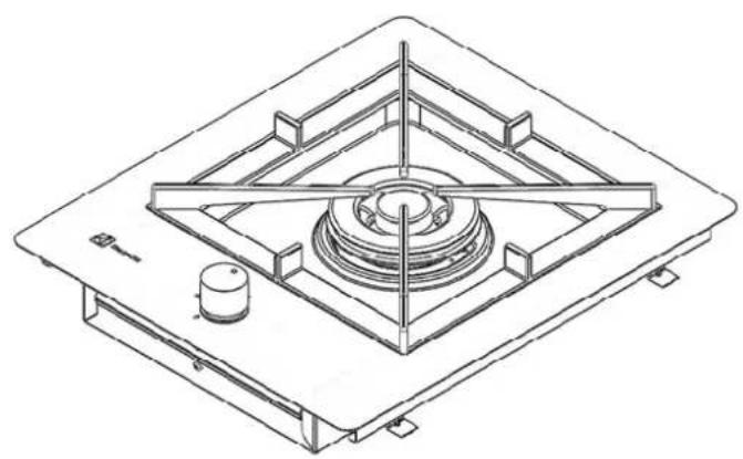
Hobs can be equipped by stainless steel grids (see picture 2) or cast iron grids (bigger and heavy – see picture 3).
The grids can be taken off to enable a better cleaning. Lift the grids up from the hob.
Grids and chromium-plated grids caps.
Grids and chromium-plated grids caps tend to darken with their use. This is an absolute regular and unavoidable phenomenon but it does not absolutely compromise the hob functionality..
By the way, upon request, there are enamelled grids and grids caps available by your retailer or our Technical Assistance Centres.

natural_image
Technical line drawing of a gas stove with cooling unit and heating element (no text or symbols)Picture 2
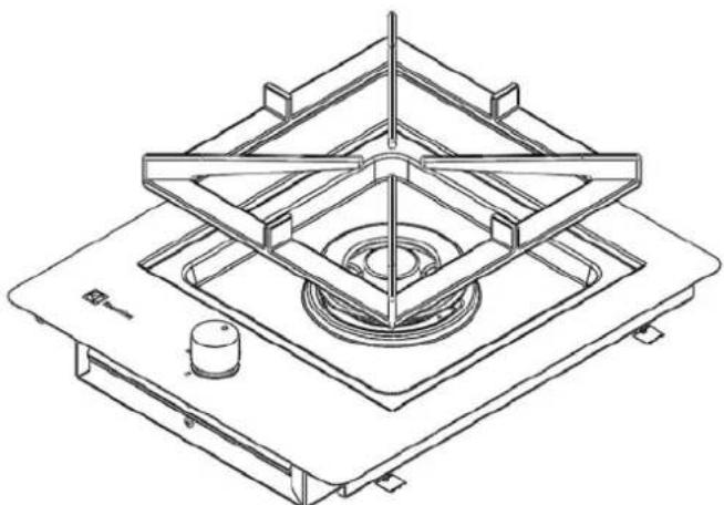
natural_image
Technical line drawing of a mechanical assembly with nested frame and central hub (no text or symbols)Picture 3
Periodic maintenance.
The condition of the gas-supply pipe should be checked periodically and, if present, the condition of the pressure control. If you find any irregularities do not ask to repair them but ask for their replacement. To grant the proper working and safety it is necessary to periodically grease the gas regulation cocks.
The periodic lubrication of the gas cocks must be done by QUALIFIED PERSONNEL ONY whom has to be contacted in case of anomalies to the appliance working.
Assistance and spare parts.
This appliance, before leaving the warehouse, has been tested and set by qualified personnel to obtain the best working performance. If any repairs are required, they have to be done with the maximum care and attention. For this reason we recommend you to contact the retailer who dealt with the sale or the closest Assistance Centre, specifying the type of inconvenience, the appliance model (Mod.), the product number (Prod. No.) and the manufacturing number (Ser. No.). These datum are indicated on the label on the last page og the handbook.
Original spare parts, certified by the product manufacturer and countersigned by this brand, are available by our Technical Assistance Centres and Authorized Spare Parts Shops only.
Electrolux
Distriparts
Guarantee conditions
This new appliance is covered by guarantee. The guarantee conditions are fully indicated on the leaflet "TOP SERVICE", which will be found on the inside of the appliance.
Hold carefully, with the leaflet "TOP SERVICE" the receipt or the transport bill, useful to support the purchase of his appliance and the date of it.
In case of intervention by the Assistance Service, show these documents to the charged personnel. Without the respect of this procedure, the Assistance Service will be obliged to debit you any eventual repairs.
The Technical Assistance Service, throughout its numerous authorized Centres, gives assistance in Italy to the most prestigious brands of appliances. If necessary you can look for the closest Centre by consulting the “TOP SERVICE” leaflet.

Technical features
Gas burners power
| Ultra-rapid treble crown burner (big) | 4,0 Kw |
| Rapid burner (big) | 3,0 Kw |
| Auxiliary burner (small) | 1,0 kW |
| Semi-rapid burner (medium) | 2,0 kW |
Category
II2H3+
| Appliance Calibration | Methane Gas 20 mbar |
| Gas inlet connector | G 1/2" |
| Feeling tension | 230 V 50 Hz |
Dimensions for the recess opening
| Width | 447 mm |
| Depth | 382 mm |
Instructions for the installer
WARNING: This appliance can be installed and can work only in permanently well-ventilated rooms in accordance with o UNI 7129 e UNI 7131 regulations. The installation of the appliance and the connection to the electric network must be carried out exclusively by QUALIFIED PERSONNEL ONLY. Before doing any sort intervention it is important to verify the equipment is disconnected from the electrical network
THE CONSTRUCTOR COMPANY DECLINES FROM ANY RESPONSABILITY IN CASE OF DEMAGES CAUSED BY AN INSTALLATION NOT IN COMPLIANCE WITH THE CURRENT REGULATIONS AND WITHOUT RESPECTING THE ACCIDENT PREVENTION RULES.
Room of installation
In order to have a proper working of the gas appliance it is of main importance to grant a natural air circulation in the room, the air necessary for the gas combustion. (the installer must strictly follow the current directives UNI-CIG 7129 - 7131).
The air circulation must be ensured through openings in walls to the outside (as indicated in picture 7).
These openings must have a free passing section of at least 100 cm _2 .
This opening must be made in such a way that cannot be obstructed from the outside, near the floor level and positioned on the opposite side of the exhaust system.
If this opening cannot be made in the room where the appliance is installed, the necessary air can come from a near room, but:
this room cannot be a bedroom;
this room cannot be in depression;
the ventilation between the room where the appliance is installed and the near room has to be insured by permanent openings. (UNI-CIG 7129).
If you install the hob under a hood, please see the installation instructions of the hood for the minimum distance between the appliances.

Picture 7
Discharge of flue gases
Cooking appliances must always discharge the flue gases into special hoods, which must be connected to chimneys or have direct access to the outside.(picture7). If it is not possible to install a hood, it is necessary the employment of an electric fan fitted to the external wall or to the window, as long as there are the conditions for the increase of the ventilation (see picture 8), reported to the power of the fan itself. (UNI-CIG7129).
This electric fan must have the necessary power to grant, for a kitchen, an hour air change of 3-5 times its volume.

Picture 8
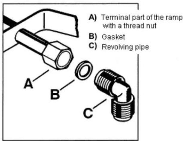
Picture 9
Connection to the gas-supply.
The cooker should be connected according UNI-CIG 7129 - 7131 directives. The appliance is tested and adjusted to operate with the type of gas stated on the rating plate applied in the inferior protection, closed to the connection gas-supply pipe.
Make sure the type of gas you will use to feed the appliance is the same indicated on the label.
In the contrary case proceed referring to the paragraph "Adjustment to the different gas types".
For the best performance and the lowest consume, make sure that the gas pressure respect the values indicated in the table "Features of the burners".
If the applied gas pressure is different (or variable) from the scheduled one, it is necessary to install, on the inlet pipe, a proper gas pressure regulator for gas (NON GPL) in compliance with UNI-CIG 7430.
The use of pressure regulators for liquid (GPL) is permitted but it has to be in appliance to the UNI-CIG 7432 Directive.
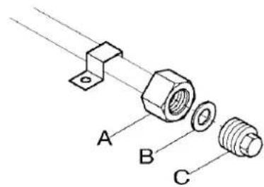
On the terminal part of the ramp with a thread nut G 1/2" the pipe fitting has to be mounted, putting between the parts, the washer as indicated in picture 9. Screw the parts without forcing, position the washer toward the requested direction and tighten everything.
Gas connection
The connection of the hob to the gas pipe network must be made by means of a rigid metallic pipe complying with the UNI-CIG 7129 directive or using a flexible connection according to the UNI-CIG 9891 directive, which can be extended to a maximum length of 2 metres. Pay attention, in case of employment of flexible metal pipes, they do not get in touch with moving parts or get crushed. Pay attention even if you combine a hob and an oven. The gas inlet washer in the appliances is thread 12 " male cylinder. Carry out the gas connection avoiding any sort of stress to the appliance.
At complete gas connection, always verify the perfect hold of all the washers by using a soapy solution. Never carry out this control using a flame
Electrical connection
The appliance is set up for a single-phase 230V feeling voltage. The connection has to be carried out in compliance with the current directives and law dispositions.
Before connecting the hob make sure that:
The shaping valve and the electrical system can stand the appliance load (see the serial number indicated on the rating plate):
The feed system of the appliance has a proper earth connection, according the laws in force;
The tap or the single-pole circuit breaker are easy to be reached from the installed appliance.
Mount on the cable a suitable tap for the load and connect it to a proper safety tap.
If a straight connection to the electricity is desired, it is necessary to put a single-pole, with a minimum opening of 3mm dimensioned to the load and in compliance with the current directives, between the appliance and the network.
The brown phase wire (coming out from the L terminal on the terminal board) must be always connected to the phase of the feeding network.
In any case the feeding wire has to be positioned so that it cannot reach, anywhere in its length, a temperature higher than 90°C.
An example of optimal current path is indicated on picture 10. The wire is guided by the employment of clamps fixed on the side of the furniture, in order to avoid any contact with the appliance under the hob

Picture 10
Replacing the electrical power cable
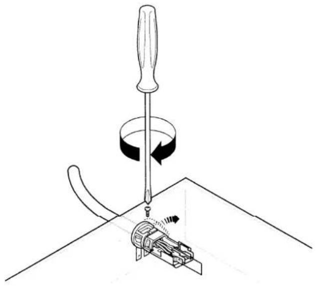
If necessary the electrical power must be replaced exclusively with power cables type H05V2V2-F T90 suitable for the load and temperature rating. It is also important that the earth wire (Yellow/Green) must be at least 2 cm longer than the other phase neutral (picture 11)-(picture 12). After the connection test the heating elements letting them work bout 3 minutes.

Picture 11
natural_image
Diagram of a screwdriver using a tool to adjust a mechanical component (no text or symbols present)Picture 12
Electrical diagram of the top

Adjustment to different types of gas
Replacing the nozzles
- Remove the grids.
- Remove the grid caps and burnes' crowns.
- With a 7 socket spanner unscrew and take out the nozzles (picture 13), substitute them with those corresponding to the working gas type (see table next page).
- Reassemble the parts/elements by executing the above described operations in the opposite direction.
- Substitute the calibration rating plate (positioned near the feed ear). This last one is in the small bag of the injectors' kit.
If the pressure of the gas applied is different (or variable) from the scheduled one, it is necessary to install on the inlet tube, a proper pressure regulator for gases (NOT GPL) in compliance with the UNI-CIG 7430.
The employment of pressure regulators for liquid gas (GPL) is allowed if complying with UNI-CIG 7432.

natural_image
Diagram of a mechanical valve assembly with a magnified inset showing internal components (no text or labels)Picture 13
Adjusting the minimum gas setting of taps.
To adjust the minimum setting proceed as follows:
- Light up the burners as previously described.
- Turn the gas cock to the minimum position.
- Take the knobs out..
- Work on the by-pass pin indicated on picture 15.
- If you pass from Methane to GPL gas, screw tight the by-pass pin in the clockwise direction.
- In any case the result must be a small, homogeneous and regular flame in the entire burner's crown.
- Verify then that by turning quickly the tap from the maximum to the minimum position, no burner's blowing-out occurs.
The described adjustment's operations can be easily done in any positioning of the hob on the kitchen furniture.

natural_image
Three-step diagram showing mechanical assembly with arrows indicating direction (no text or symbols)by-pass pin
To adjust the minimum
Picture 15
| Burner | ∅ By-pass tap in hundredth |
| Auxiliary | 28 |
| Semi-rapid | 32 |
| Rapid | 40 |
| Ultra-rapid with treble crown | 56 |
BURNERS SPECIFICATIONS
| TYPE OF GAS | TYPE OF BURNER | NOZZLES MARKING 1/100 mm | NOMINAL THERMIC RATE kW | REDUCED TERMIC RATE kW | NOMINAL IN RATE | NOMINAL PRESSURE mbar | |
| m3 /h g/h | |||||||
| NATURAL GAS (Methane) | Ultra-rapid (big) | 146 | 4,0 | 1,2 | 0,381 | - | 20 |
| Rapid | 119 | 3,0 | 0,65 | 0,305 | - | ||
| Semi-rapid (medium) | 96 | 2,0 | 0,45 | 0,190 | - | ||
| Auxiliary (small) | 70 | 1,0 | 0,33 | 0,095 | - | ||
| LIQUID GAS (Butane/Propane) | Ultra-rapid (big) | 98 | 4,0 | 1,2 | - | 288 | 28-30/37 |
| Rapid | 86 | 3,0 | 0,65 | - | 202 | ||
| Semi-rapid (medium) | 71 | 2,0 | 0,45 | - | 144 | ||
| Auxiliary (small) | 50 | 1,0 | 0,33 | - | 72 | ||
Types of cooker tops
Tops with stainless grids
Tops with iron steel grids
Auxiliary
natural_image
Technical line drawing of a mechanical assembly with a central circular component and two cylindrical components (no text or symbols)
natural_image
Technical line drawing of a mechanical assembly with a central circular component and two cylindrical components (no text or symbols)Semi-rapid

natural_image
Technical line drawing of a mechanical assembly with a central circular component and mounting base (no text or symbols)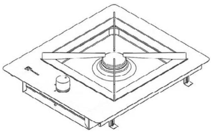
natural_image
Technical line drawing of a mechanical assembly with a central circular component and two supporting legs (no text or symbols)Triple crown
natural_image
Technical line drawing of a mechanical mounting bracket with internal components and mounting feet (no text or symbols)
natural_image
Technical line drawing of a mechanical assembly with concentric diamond-shaped components and a central circular component (no text or symbols)Positioning and connection
Cookers can be mounted on a furniture with a recess opening with dimensions shown in picture 17
The fixing of the hob to the top has to be done as follows:
Position the suitable dope or gasket (not issued), on the front, back and side edges of the worktop's opening (as shown in picture 16).
Ad just the hob on the opening of the furniture paying attention to centre it.
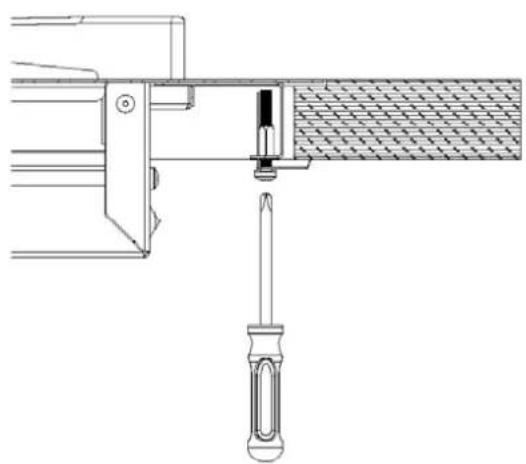
Fix the hob to the furniture using provided brackets (see picture 20).
In picture 18 and picture 19 are illustrated the outline of the connection to the electric supply and the gas supply.
For thick edge installation, execute on the top, only the hole with dimension 382x447millimetres without the ribassamento from 2 millimetres stubbling.

Picture 18
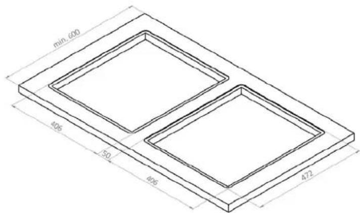
Fig.16
Picture 19
A) Ending of the ramp and nut
B) Gasket
C) Tap
natural_image
Technical line drawing of a mechanical assembly with a screwdriver inserted, showing no text or symbolsFig.20

Picture 17
Possibilities of positioning and connection


The symbol ■ on the product, or on the documents accompanying the product, indicates that this appliance may not be treated as household waste. Instead it shall be handed over to the applicable collection point for the recycling of electrical and electronic equipment.
Disposal must be carried out in accordance with local environmental regulations for waste disposal. For more detailed information about treatments, recovery and recycling of this product, please contact your local city office, your household waste disposal service or the shop where you purchased the product.

From the Electrolux Group. The world's No.1 choice.
The Electrolux Group is the world's largest producer of powered appliances for kitchen, cleaning and outdoor use. More than 55 million Group products (such as refrigerators, cookers, washing machines, vacuum cleaners, chain saws and lawn mowers) are sold each year to a value of approx. USD 14 billion in more than 150 countries around the world.
- For your safety
- Installation
- Children safety
- While using
- Suggestions for the environment protection.
- Guide to the instructions reading
- Index
- For the User
- Use instructions
- The control knobs of the cooker top
- Burners ignition
- For the installer
- For a correct use of the burners.
- Cleaning and maintenance
- General cleaning
- Cleaning of the electrical ignition
- Hob's grids.
- Grids and chromium-plated grids caps.
- Periodic maintenance.
- Assistance and spare parts.
- Electrolux
- Guarantee conditions
- Technical features
- Gas burners power
- Category
- Dimensions for the recess opening
- Instructions for the installer
- Room of installation
- Discharge of flue gases
- Connection to the gas-supply.
- Gas connection
- Electrical connection
- Replacing the electrical power cable
- Electrical diagram of the top
- Adjustment to different types of gas
- Replacing the nozzles
- Adjusting the minimum gas setting of taps.
- Types of cooker tops
- Positioning and connection
- Possibilities of positioning and connection
Brand : REX
Model : FPZ2OV
Category : Cooker