
R1208RPMSHOR - Server INTEL - Free user manual and instructions
Find the device manual for free R1208RPMSHOR INTEL in PDF.


| Product Type | 1U Rack-Mount Server |
| Processor Support | Single Intel Xeon E3-1200 V3, LGA1150, up to 95W TDP |
| Memory Support | 4 DIMM slots, DDR3L ECC UDIMM, up to 1600 MT/s |
| Chipset | Intel C226 Platform Controller Hub |
| Storage Bays | 8x 2.5-inch Hot-Swap SATA/SAS HDD/SSD Bays |
| Power Supply | 450W 1+1 Redundant Power Supply (Hot-Swap) |
| Expansion Slots | 1x PCIe 3.0 x8 (x16 connector) from CPU, 3x PCIe 2.0 x4/x8 from PCH |
| Management | Integrated BMC with IPMI 2.0, optional Remote Management Module 4 |
| Front Panel | Power button, System ID, NMI, Reset, Status LEDs, 2x USB 2.0 |
| Dimensions (Approximate) | 1.75" (44mm) H x 17.2" (437mm) W x 25.6" (650mm) D |
| Operating Temperature | 10°C to 35°C (ASHRAE A2) |
| RAID Support | Intel RSTe (SW RAID 0/1/10/5) or Intel Embedded Server RAID Technology II |
| Network | 2x Gigabit Ethernet via Intel I210 |
| Video | Integrated 2D video controller, 16MB DDR3 |
| Cooling | 3x 40mm dual-rotor system fans, fan speed control |
| Compliance | IPMI 2.0, DCMI 1.0, Energy Star (server version) |
Frequently Asked Questions - R1208RPMSHOR INTEL
User questions about R1208RPMSHOR INTEL
0 question about this device. Answer the ones you know or ask your own.
Ask a new question about this device
Download the instructions for your Server in PDF format for free! Find your manual R1208RPMSHOR - INTEL and take your electronic device back in hand. On this page are published all the documents necessary for the use of your device. R1208RPMSHOR by INTEL.
USER MANUAL R1208RPMSHOR INTEL
Intel® Server System R1000RP Family
Technical Product Specification
Intel order number: G91532-003

Revision 1.3
February 2014
Revision History
| Date | Revision Number | Modifications |
| April 2013 | 1.0 | Initial release. |
| May 2013 | 1.1 | Added a new system Intel® Server System R1304RPMSHOR. |
| May 2013 | 1.2 | Removed the system Intel® Server System R1304RPOSHOR. |
| February 2014 | 1.3 | Corrected the name of Intel® RAID Activation Key as RKSATA4R5. |
Disclaimers
INFORMATION IN THIS DOCUMENT IS PROVIDED IN CONNECTION WITH INTEL PRODUCTS. NO LICENSE, EXPRESS OR IMPLIED, BY ESTOPPEL OR OTHERWISE, TO ANY INTELLECTUAL PROPERTY RIGHTS IS GRANTED BY THIS DOCUMENT. EXCEPT AS PROVIDED IN INTEL'S TERMS AND CONDITIONS OF SALE FOR SUCH PRODUCTS, INTEL ASSUMES NO LIABILITY WHATSOEVER AND INTEL DISCLAIMS ANY EXPRESS OR IMPLIED WARRANTY, RELATING TO SALE AND/OR USE OF INTEL PRODUCTS INCLUDING LIABILITY OR WARRANTIES RELATING TO FITNESS FOR A PARTICULAR PURPOSE, MERCHANTABILITY, OR INFRINGEMENT OF ANY PATENT, COPYRIGHT OR OTHER INTELLECTUAL PROPERTY RIGHT.
A "Mission Critical Application" is any application in which failure of the Intel Product could result, directly or indirectly, in personal injury or death. SHOULD YOU PURCHASE OR USE INTEL'S PRODUCTS FOR ANY SUCH MISSION CRITICAL APPLICATION, YOU SHALL INDEMNIFY AND HOLD INTEL AND ITS SUBSIDIARIES, SUBCONTRACTORS AND AFFILIATES, AND THE DIRECTORS, OFFICERS, AND EMPLOYEES OF EACH, HARMLESS AGAINST ALL CLAIMS COSTS, DAMAGES, AND EXPENSES AND REASONABLE ATTORNEYS' FEES ARISING OUT OF, DIRECTLY OR INDIRECTLY, ANY CLAIM OF PRODUCT LIABILITY, PERSONAL INJURY, OR DEATH ARISING IN ANY WAY OUT OF SUCH MISSION CRITICAL APPLICATION, WHETHER OR NOT INTEL OR ITS SUBCONTRACTOR WAS NEGLIGENT IN THE DESIGN, MANUFACTURE, OR WARNING OF THE INTEL PRODUCT OR ANY OF ITS PARTS.
Intel may make changes to specifications and product descriptions at any time, without notice. Designers must not rely on the absence or characteristics of any features or instructions marked "reserved" or "undefined". Intel reserves these for future definition and shall have no responsibility whatsoever for conflicts or incompatibilities arising from future changes to them. The information here is subject to change without notice. Do not finalize a design with this information.
The products described in this document may contain design defects or errors known as errata which may cause the product to deviate from published specifications. Current characterized errata are available on request.
Contact your local Intel sales office or your distributor to obtain the latest specifications and before placing your product order.
Copies of documents which have an order number and are referenced in this document, or other Intel literature, may be obtained by calling 1-800-548-4725, or go to: http://www.intel.com/design/literature.
Table of Contents
1. Introduction .... 1
1.1 Chapter Outline .... 1
1.2 Server Board Use Disclaimer .... 1
2. Product Overview....2
2.1 System Views....4
2.2 System Dimensions....5
2.3 System Level Environmental Limits....5
2.4 System Features and Options Overview 7
2.4.1 Hot Swap Hard Drive Bay and Front Panel Options 7
2.4.2 Back Panel Features....8
2.4.3 Front Control Panel Options 8
2.5 Server Board Overview 9
2.5.1 Rear Component View 11
2.6 Available Front Bezel Support (Optional)....11
2.7 Available Rack and Cabinet Mounting Kit Options....12
3. Power Subsystem....13
3.1 350W Fixed Power Supply ....13
3.1.1 Mechanical Overview....13
3.1.2 Power Supply Module Efficiency 14
3.1.3 Power Cord Specification Requirements 14
3.1.4 AC Input Requirement....15
3.1.5 DC Output Specification....18
3.1.6 Protection Circuits....18
3.2 450W mini-ERPS Redundant Power Supply 19
3.2.1 Mechanical Overview 20
3.2.2 Power Supply Module Card Edge Connector 21
3.2.3 Power Supply Module Efficiency 22
3.2.4 Power Cord Specification Requirements 22
3.2.5 AC Input Requirement....22
3.2.6 DC Output Specification....26
3.2.7 Protection Circuits....26
4 Thermal Management....28
4.1 Thermal Operation and Configuration Requirements....28
4.2 Thermal Management Overview 29
4.2.1 Set Throttling Mode....29
4.2.2 Altitude 30
4.2.3 Set Fan Profile 30
4.2.4 Fan PWM Offset....30
4.2.5 Quiet Fan Idle Mode....30
4.2.6 Thermal Sensor Input for Fan Speed Control 30
4.3 System Fans 32
4.4 FRUSDR Utility 34
5 System Storage and Peripheral Options....35
5.1 2.5" Hard Disk Drive Support....35
5.1.1 2.5" Drive Hot-Swap Backplane Overview....36
5.1.2 Cypress* CY8C22545 Enclosure Management Controller....37
5.2 3.5" Hard Disk Drive Support....37
5.2.1 3.5" Drive Hot-Swap Backplane Overview....38
5.2.2 Cypress* CY8C22545 Enclosure Management Controller....39
5.3 SATA DOM Support....39
6 Storage Controller Options Overview 40
6.1 Embedded SATA Controller Support....40
7 Front Control Panel and I/O Panel Overview 41
7.1 I/O Panel Features 41
7.2 Control Panel Features 41
8 Intel ^® Local Control Panel....46
8.1 LCD Functionality....46
8.2 Main Menu 47
8.3 Event Menu 48
8.4 View Menu 48
8.4.1 System FW Version (SysFwVer) 48
8.4.2 System Information (SysInfo) 49
8.4.3 BMC IP Configuration....49
8.4.4 RMM4 IP Configuration....49
8.4.5 Power....50
8.4.6 Last Post Code (Last PC)....50
8.5 Config Menu....50
8.5.1 IP Version 50
8.5.2 BMC IP....50
8.5.3 RMM4 IP 52
8.5.4 Boot Device....52
8.5.5 Banner 52
9 PCIe Support and Riser Card Support....54
9.1 Architectural Overview of the Server Board Riser Slots....54
Appendix A: Integration and Usage Tips ....57
Appendix B: POST Code LED Decoder ....58
Appendix C: POST Code Errors....63
Glossary 69
Reference Documents....72
List of Figures
Figure 1. Product Drawing ......2
Figure 2. System Photo....4
Figure 3. Chassis Dimension ....5
Figure 4. System Components Overview ......7
Figure 5. 3.5" Hard Drive Bay - 4 Drive Configuration ....7
Figure 6.2.5" Hard Drive Bay - 8 Drive Configuration ....7
Figure 7. Back Panel Feature Identification (Redundant Power Supply as Shown)....8
Figure 8. Front Control Panel Options....8
Figure 9. Intel ^® Server Board S1200V3RPS....9
Figure 10. Intel ^® Server Board S1200V3RPO and S1200V3RPM ..... 10
Figure 11. Intel ^® Server Board S1200V3RP Rear Components....11
Figure 12. Optional Front Bezel ......11
Figure 13. Installing Front Bezel....12
Figure 14. 350W AC Power Supply Unit Enclosure Drawing....14
Figure 15. AC Power Cord....15
Figure 16. 450W AC PSU with PDB....20
Figure 17. 450W AC Power Supply Unit Dimension Overview ......20
Figure 18. 450W AC Power Supply – Connector View....21
Figure 19. 450W Power Supply Module Output Power Connector ....21
Figure 20. AC Power Cord ....22
Figure 21. Fan Control Model....31
Figure 22. System Fan Identification....32
Figure 23. Removing a System Fan....32
Figure 24. Server Board System Fan Connector Locations....33
Figure 25. 2.5" Hard Drive Bay Drive Configuration ....35
Figure 26. LED of HDD Carrier ....35
Figure 27. The Front Side of 8 X 2.5" Hot Swap Backplane ....36
Figure 28. The Back Side of 8 X 2.5" Hot Swap Backplane....36
Figure 29. 3.5" Hard Drive Bay Configuration....37
Figure 30. LED of HDD Carrier ....37
Figure 31. The Front Side of 4 x 3.5" Hot Swap Backplane....38
Figure 32. The Back Side of 4 x 3.5" Hot Swap Backplane ....38
Figure 33. InnoDisk* Low Profile SATA DOM....39
Figure 34. SATA_KEY Place....40
Figure 35. Front I/O Panel Features....41
Figure 36. Front Control Panel Features ....42
Figure 37. Intel ^® Local Control Panel Option 46
Figure 38. LCP Background Color during Normal Operation....47
Figure 39. LCP Background Color during an Error 47
Figure 40. LCP Main Menu ....47
Figure 41. LCP Event Menu....48
Figure 42. LCP View Menu ....48
Figure 43. System Firmware Versions Menu....48
Figure 44. System Information Menu ....49
Figure 45. LCP – BMC IP Configuration....49
Figure 46. LCP – RMM4 IP Configuration ....50
Figure 47. LCP – Power Consumed by the System Currently ....50
Figure 48. LCP – Last BIOS Post Code ....50
Figure 49. LCP – Configure Menu Items....50
Figure 50. LCP – IP Version Configuration Screen ....50
Figure 51. LCP – BMC IP Configuration Menu....51
Figure 52. LCP – BMC IP Source Configuration Menu....51
Figure 53. Screen Shot for Configuring IP Address, Subnet Mask, and Gateway....51
Figure 54. State Transition Diagram for Setting IP Address ....52
Figure 55. Boot options Configuration Menu ....52
Figure 56. Banner Configuration Menu ....53
Figure 57. PCIe SLOT Drawing....55
Figure 58. 1U Riser Card Drawing ....56
Figure 59. Diagnostic LED Location....58
List of Tables
Table 1. System Feature Set....2
Table 2. System SKU Matrix ....4
Table 3. System Environmental Limits Summary ....5
Table 4. Output Load for Efficiency Test ....14
Table 5. AC Power Cord Specifications ....14
Table 6. Power Factor....15
Table 7. AC Input Voltage Range....15
Table 8. AC Line Sag Transient Performance....16
Table 9. AC Line Surge Transient Performance....17
Table 10. Performance Criteria ...... 17
Table 11. Output Current Requirements....18
Table 12. Over Load Protection (OCP) Limits ......19
Table 13. Over Voltage Protection (OVP) Limits ......19
Table 14. 450W Power Supply Module Output Power Connector Pin-out .....21
Table 15. 450WAC Power Supply Efficiency....22
Table 16. AC Power Cord Specifications....22
Table 17. AC Input Voltage Range....23
Table 18. AC Line Sag Transient Performance ......24
Table 19. AC Line Surge Transient Performance....24
Table 20. Performance Criteria ...... 25
Table 21. Load Ratings....26
Table 22. Over Current Limits ......26
Table 23. Over Voltage Protection (OVP) Limits ......27
Table 24. System Fan Connector Pin-out....34
Table 25. Drive Status LED States....35
Table 26. Drive Activity LED States....36
Table 27. System Status LED State Definitions....43
Table 28. Power/Sleep LED Functional States....45
Table 29. PCI Express* Speed Matrix for Each Configuration....54
Table 30. POST Progress Code LED Example ....58
Table 31. Diagnostic LED POST Progress Codes....59
Table 32. MRC Progress Codes ....61
Table 33. MRC Fatal Error Codes....62
Table 34. POST Error Message and Handling ......63
Table 35. POST Error Beep Codes....67
Table 36. Integrated BMC Beep Codes....68
Intel ^® Server System R1000RP Family TPS
(This page is intentionally left blank.)
1. Introduction
This Technical Product Specification (TPS) provides system specific information detailing the features, functionality, and high-level architecture of the Intel® Server System R1000RP family. You can also reference the Intel® Server Board S1200V3RP Family Technical Product Specification to obtain greater detail of functionality and architecture of the server board integrated in this server system.
In addition, you can obtain design-level information for specific subsystems by ordering the External Product Specifications (EPS) or External Design Specifications (EDS) for a given subsystem. EPS and EDS documents are not publicly available. They are only made available under NDA with Intel and must be ordered through your local Intel representative. For a complete list of available documents, refer to the Reference Documents section at the end of this document.
The Intel ^® Server System R1000RP may contain design defects or errors known as errata which may cause the product to deviate from published specifications. Refer to the Intel ^® Server Board S1200V3RP / Intel ^® Server System R1000RP Specification Update for published errata.
1.1 Chapter Outline
This document is divided into the following chapters:
■ Chapter 1 – Introduction
■ Chapter 2 – Product Overview
■ Chapter 3 – Power Subsystem
■ Chapter 4 – Thermal Management
- Chapter 5 – System Storage and Peripheral Options
- Chapter 6 – Storage Controller Options Overview
- Chapter 7 – Front Control Panel and I/O Panel Overview
■ Chapter 8 – Intel ^® Local Control Panel
- Chapter 9 – PCIe Support and Riser Card Support
- Appendix A – Integration and Usage Tips
- Appendix B – POST Code LED Decoder
■ Appendix C – POST Code Errors
■ Glossary
■ Reference Documents
1.2 Server Board Use Disclaimer
Intel Corporation server boards support add-in peripherals and contain a number of high-density VLSI and power delivery components that need adequate airflow to cool. Intel ensures through its own chassis development and testing that when Intel ^® server building blocks are used together, the fully integrated system will meet the intended thermal requirements of these components. It is the responsibility of the system integrator who chooses not to use Intel developed server building blocks to consult vendor datasheets and operating parameters to determine the amount of air flow required for their specific application and environmental conditions. Intel Corporation cannot be held responsible if components fail or the server board does not operate correctly when used outside any of their published operating or non-operating limits.
2. Product Overview
This generation of Intel® 1U server platforms offers a variety of system options to meet the entry level computing. The Intel® Server System R1000RP product family is comprised of several available 1U rack mount server systems that are all integrated with an Intel® Server Board S1200V3RPS, S1200V3RPO, or S1200V3RPM.
This chapter provides a high-level overview of the system features. The following chapters provide greater detail for each major system component or feature.
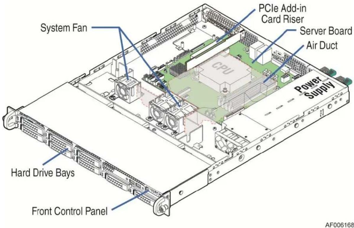
Figure 1. Product Drawing
Table 1. System Feature Set
| Feature | Description | ||||
| Processor | Support for one Intel ^® Xeon ^® processor E3-1200 V3 processor in an LGA 1150 Socket H3 package with Thermal Design Power up to 95W.5 GT/s point-to-point DMI 2.0 interface to PCH. | ||||
| Memory | Two memory channels, four memory DIMMs (Two memory DIMMs per channel).Support for 1333/1600 MT/s Unbuffered (UDIMM DDR3L ECC memory).No support for RDIMMs.No support for SODIMMs.No support for mixing ECC and non-ECC UDIMMs. | ||||
| Chipset | S1200V3RPS supports for Intel ^® C222 Platform Controller Hub (PCH) chipset.S1200V3RPO supports for Intel ^® C224 Platform Controller Hub (PCH) chipset.S1200V3RPM supports for Intel ^® C226 Platform Controller Hub (PCH) chipset. | ||||
| System Connectors /Headers | External I/O connectors:DB9 serial port A connection.One DB-15 video connector.Two RJ-45 NIC connectors for 10/100/1000 Mb connections through the two Intel ^ Ethernet Controller I210.Two USB 3.0 ports at the back of the board.Two USB 2.0 ports at the back of the board.Internal connectors/headers:One 2x10 pin USB 3.0 header, providing front panel support for two USB ports respectively on S1200V3RPO/S1200V3RPM.One 2x5 pin USB 2.0 headers, providing front panel support for two USB ports respectively.One internal 2x5 pin serial port B header.One internal Type-A USB 2.0 port.One 9 pin USB header for eUSB SSD.One 1x7 pin header for optional Intel ^ Local Control Panel support.One combined header consists of a 24-pin SSI-EEB compliant front panel header. | ||||
| System Fan Support | Support for:One processor fan (4-pin header).Three front system fans (4-pin headers). | ||||
| Add-in Adapter Support | Four expansion slots at most:Slot 7: PCI Express* Gen2 x1 electrical with x8 physical connector, from PCH.Slot 6: PCI Express* Gen3 x8 electrical with x16 physical connector, from processor.Slot 5: PCI Express* Gen2 x8 or x4 electrical with x8 physical connector, from processor.Slot 4: PCI Express* Gen2 x4 electrical with x8 physical connector, from PCH.Slot Population Per SKU | ||||
| SKU/Slot | Slot 4 | Slot 5 | Slot 6 | Slot 7 | |
| S1200V3RPS | Yes | Yes | Yes | Yes | |
| S1200V3RPO | NA | NA | Yes | NA | |
| S1200V3RPM | NA | NA | Yes | NA | |
| On-board Video | Integrated 2D video controller.Dual monitor video mode is supported.16 MB DDR3 Memory.Only S1200V3RPM supports integrated graphics support for processors with Intel ^ Graphics Technology. | ||||
| Hard Disk Drive Supported | 4x 3.5-inch SATA/SAS HDD bays (SKU: R1304RPSSFBN, R1304RPOSHBN, and R1304RPMSHOR).8x 2.5-inch SATA/SAS HDD bays (SKU: R1208RPOSHOR and R1208RPMSHOR). | ||||
| RAID Support | Intel ^ RSTe SW RAID through onboard SATA connectors provides SATA RAID 0/1/10/5.Intel ^ Embedded Server RAID Technology II through onboard SATA connectors provides SATA RAID 0/1/10 and optional RAID 5 support provided by the Intel ^ RAID Activation Key RKSATA4R5.S1200V3RPO supports one optional internal SAS module connector which supports Intel ^ SAS or ROC modules with the product code of RMS25CB080, RMS25JB080, RMS25CB040, and RMS25JB040. | ||||
| LAN | Two Gigabit Ethernet Ports through the two Intel ^ Ethernet Controller I210 PHYs. | ||||
| System Power | 350W Fixed (SKU: R1304RPSSFBN and R1304RPOSHBN).450W Redundant (SKU: R1208RPOSHOR, R1304RPMSHOR, and R1208RPMSHOR). | ||||
| Server Management | Integrated Baseboard Management Controller, IPMI 2.0 compliant.Support for Intel ^® Remote Management Module 4 solutions (Optional except on S1200V3RPS).Support for Intel ^® Remote Management Module 4 Lite solutions (Optional except on S1200V3RPS).Support for Intel ^® System Management Software.Support for Intel ^® Intelligent Power Node Manager (Need PMBus*-compliant power supply). | ||||
Note:
The USB ports on the front are USB 2.0 ports on Intel® Server System R1304RP family. The USB ports on the front can get USB 3.0 on Intel® Server System R1304RPOSHBN/R1208RPOSHOR/R1208RPMSHOR after updating the optional USB cable. You can get the product order code from Intel® Server Board S1200V3RP Configure Guide.
Table 2. System SKU Matrix
| Board SKU vs Chassis | 350W Fixed | 450W Redundant |
| 3.5" HDD | R1304RPSSFBN/R1304RPOSHBN | R1304RPMSHOR |
| 2.5" HDD | NA | R1208RPOSHORR/1208RPMSHOR |
The 3.5" HDD systems can only support 3.5" HDDs or SSD. It cannot support 2.5" HDDs.
The Intel ^® Server System R1000RP family are supporting Intel ^® Xeon ^® processor E3-1200 V3 series with TDP 95W and below. You can find a full list of supported processors at the Intel ^® Support website: https://serverconfigurator.intel.com/sct_private/sct_app.aspx.
2.1 System Views
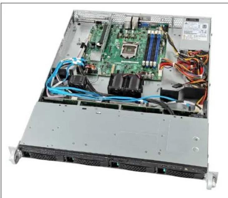
natural_image
Interior view of a server rack with visible CPU socket, RAM slots, and network cables (no text or symbols)Figure 2. System Photo
2.2 System Dimensions
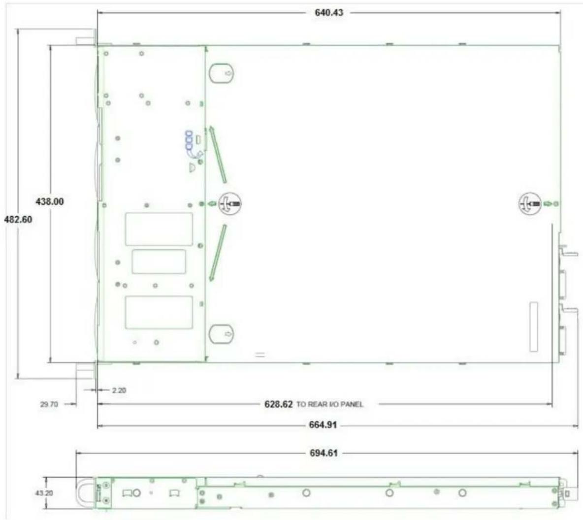
Figure 3. Chassis Dimension
2.3 System Level Environmental Limits
The following table defines the system level operating and non-operating environmental limits.
Table 3. System Environmental Limits Summary
| Parameter | Limits | |
| Temperature | ||
| Operating | ASHRAE Class A2 – Continuous Operation. 10^ C to 35^ C ( 50^ F to 95^ F) with the maximum rate of change not to exceed 10^ C per hour. | |
| Shipping | -40^ C to 70^ C ( -40^ F to 158^ F). | |
| Altitude | ||
| Operating | Support operation up to 3050m with ASHRAE class deratings. | |
| Humidity | ||
| Shipping | 50% to 90%, non-condensing with a maximum wet bulb of 28°C (at temperatures from 25°C to 35°C). | |
| Shock | ||
| Operating | Half sine, 2g, 11 mSec. | |
| Unpackaged | Trapezoidal, 25g, velocity change is based on packaged weight. | |
| Packaged | Product Weight: ≥ 40 to < 80.Non-palletized Free Fall Height = 18 inches.Palletized (single product) Free Fall Height = NA. | |
| Vibration | ||
| Unpackaged | 5 Hz to 500 Hz 2.20 g RMS random. | |
| Packaged | 5 Hz to 500 Hz 1.09 g RMS random. | |
| AC-DC | ||
| Voltage | 90 V to 132 V and 180 V to 264 V. | |
| Frequency | 47 Hz to 63 Hz. | |
| Source Interrupt | No loss of data for power line drop-out of 12 mSec. | |
| Surge Non-operating and operating | Unidirectional | |
| Line to earth Only | AC Leads 2.0 kVI/O Leads 1.0 kVDC Leads 0.5 kV | |
| ESD | ||
| Air Discharged | 12.0 kV | |
| Contact Discharge | 8.0 kV | |
| Acoustics Sound Power Measured | ||
| Power in Watts | <300 W ≥300 W ≥600 W ≥1000 W | |
| Servers/Rack Mount BA | 7.0 7.0 7.0 7.0 |
Note:
See the Intel ^® S1200V3RP Product Family Power Budget and Thermal Configuration Tool for system configuration requirements and limitations.
Disclaimer Note: Intel ensures the unpackaged server board and system meet the shock requirement mentioned above through its own chassis development and system configuration. It is the responsibility of the system integrator to determine the proper shock level of the board and system if the system integrator chooses different system configuration or different chassis. Intel Corporation cannot be held responsible, if components fail or the server board does not operate correctly when used outside any of its published operating or non-operating limits.
2.4 System Features and Options Overview
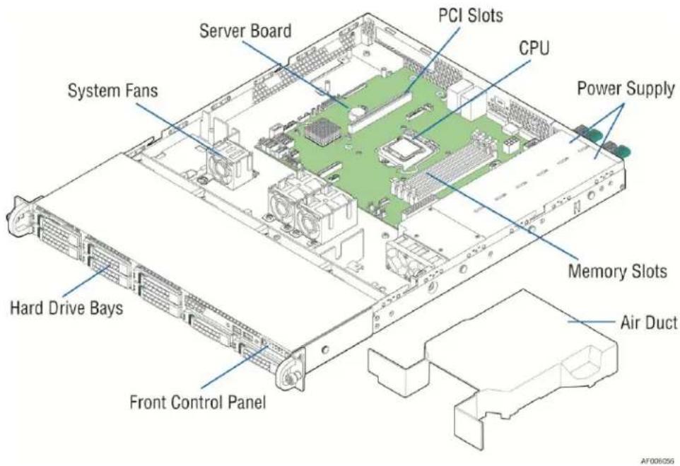
Figure 4. System Components Overview
2.4.1 Hot Swap Hard Drive Bay and Front Panel Options

Figure 5. 3.5" Hard Drive Bay - 4 Drive Configuration

Figure 6. 2.5" Hard Drive Bay - 8 Drive Configuration
2.4.2 Back Panel Features
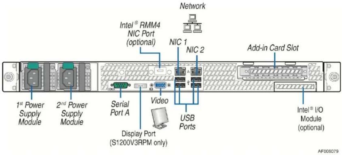
Figure 7. Back Panel Feature Identification (Redundant Power Supply as Shown)
2.4.3 Front Control Panel Options
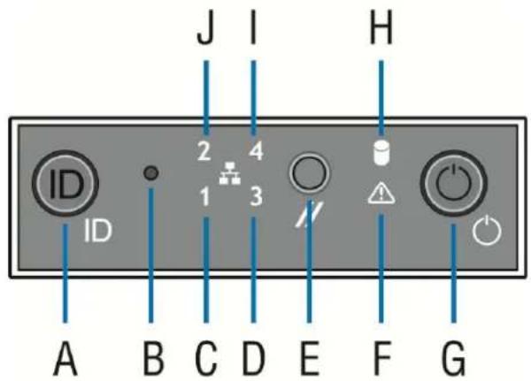
AF004065
| Label | Description | Label | Description |
| A | System ID Button w/Integrated LED | F | System Status LED |
| B | NMI Button (recessed, tool required for use) | G | Power Button w/Integrated LED |
| C | NIC-1 Activity LED | H | Hard Drive Activity LED |
| D | NIC-3 Activity LED | I | NIC-4 Activity LED |
| E | System Cold Reset Button | J | NIC-2 Activity LED |
Figure 8. Front Control Panel Options
2.5 Server Board Overview
The chassis is mechanically and functionally designed to the standard form factor and half width server board, including Intel® Server Board S1200V3RP. The following sections provide an overview of the server board feature sets.
The following figures show the layout of the server boards with each connector and major component identified.
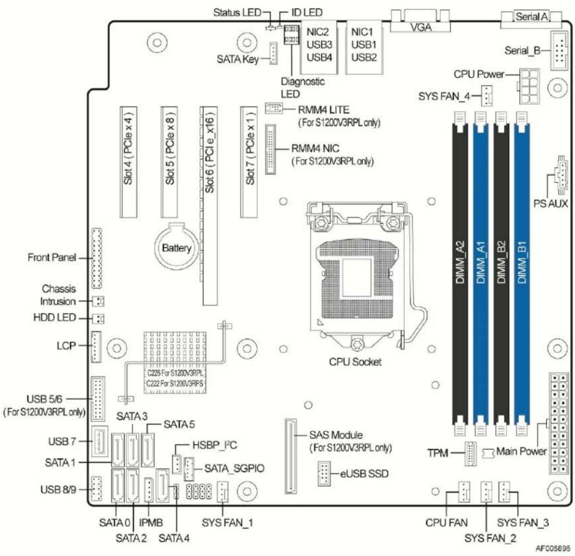
Figure 9. Intel ^® Server Board S1200V3RPS
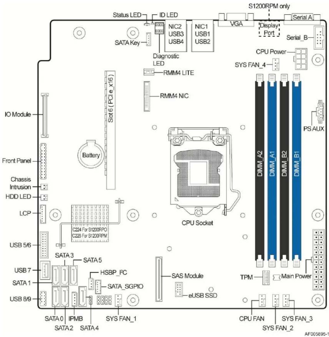
Figure 10. Intel ^® Server Board S1200V3RPO and S1200V3RPM
2.5.1 Rear Component View
The following figure shows the layout of the server board with each connector and major component identified. The description is given below in the table.
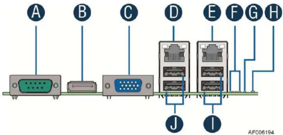
| Description | Description | ||
| A | Serial A port | F | Diagnostic LED |
| B | Display port (only for R1208RPMSHOR) | G | ID LED |
| C | DB15 Video out | H | Status LED |
| D | NIC port (RJ45) | I | USB connectors (USB 2.0) |
| E | NIC port (RJ45) | J | USB connectors (USB 3.0) |
Figure 11. Intel ^® Server Board S1200V3RP Rear Components
2.6 Available Front Bezel Support (Optional)
The optional front bezel is made of molded plastic and uses a snap-on design. When installed, its design allows for maximum airflow to maintain system cooling requirements. The face of the bezel assembly includes optional snap-in identification badge and wave (shown) features to allow for customization.
(Intel® Product Order Code – A1UBEZEL)

natural_image
Metal grate with a red circular button and a rectangular opening, no visible text or symbolsFigure 12. Optional Front Bezel
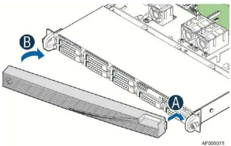
Figure 13. Installing Front Bezel
2.7 Available Rack and Cabinet Mounting Kit Options
- Tool-less rack mount rail kit – Intel ^ Product Code – AXXPRAIL
- 1U and 4U compatible
- 65 lbs maximum support weight
- Tool-less installation
o Full extension from rack - Optional cable management arm support
- Value rack mount rail kit – Intel ^ Product Code – AXXELVRAIL
- 1U to 4U compatible
- 110 lbs maximum support weight
- Tool-less chassis attach
- Tools required to attach rails to rack
- 2/3 extension from rack
- Cable Management Arm – Intel ^ Product Code – AXX1U2UCMA (supported with AXXPRAIL only)
- 2-Post Fixed mount bracket kit – Intel ^ Product Code - AXX2POSTBRCKT
CAUTION: THE MAXIMUM RECOMMENDED SERVER WEIGHT FOR THE RACK RAILS CAN BE FOUND at http://www.intel.com/support/motherboards/server/sb/CS-033655.htm. EXCEEDING THE MAXIMUM RECOMMENDED WEIGHT OR MISALIGNMENT OF THE SERVER MAY RESULT IN FAILURE OF THE RACK RAILS HOLDING THE SERVER. Use of a mechanical assist to install and align server into the rack rails is recommended.
3. Power Subsystem
This chapter provides a high level overview of the power management features and specification data for the power supply options available for this server product. Specification variations are identified for each supported power supply. There are two power supply options available in Intel® Server System R1000RP Family: 350W fixed power supply and 450W redundant power supply.
The redundant power supply platform can have up to two power supply modules installed, supporting the following power supply configurations: 1+0 (single power supply), 1+1 Redundant Power, and 2+0 Combined Power (non-redundant). 1+1 redundant power and 2+0 combined power configurations are automatically configured depending on the total power draw of the system. If the total system power draw exceeds the power capacity of a single power supply module, power from the second power supply module will be utilized. If this occurs, power redundancy will be lost. In a 2+0 power configuration, total power available may be less than twice the rated power of the installed power supply modules due to the amount of heat produced with both supplies providing peak power. If system thermals exceed the programmed limits, platform management will attempt to keep the system operational.
In the event of a power supply failure, redundant 1+1 power supply configuration (for 450W AC platform) has support for hot-swap extraction and insertion.
3.1 350W Fixed Power Supply
This section describes the performance characteristic of a single-phase full range AC input, active power factor correction switching power supply with 350 Watts output including +12V1, +12V2, +5V, +3.3V, -12V, and +5VSB.
3.1.1 Mechanical Overview
The physical size of the power supply enclosure is intended to accommodate power ranges from 350 W. The power supply size is 40 mm x 106 mm x 300 mm and has a wire harness for the DC outputs. The AC input plugs directly into the external face of the power supply; refer to the following figure for more information.
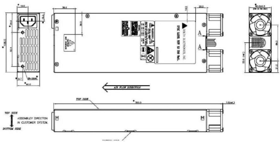
Figure 14. 350W AC Power Supply Unit Enclosure Drawing
3.1.2 Power Supply Module Efficiency
The power supply operates with efficiency ≥ 85% under 20% and 100% loads, ≥ 88% under 50% loads which are shown in the following table at 115V or 230V AC input voltages, 25^ .
Table 4. Output Load for Efficiency Test
| Output | 20% Load (A) | 50% Load (A) | 100% Load (A) |
| +3.3V | 1.3 | 3.4 | 6.8 |
| +5V | 2.2 | 5.5 | 10.9 |
| +12V1 | 2.2 | 5.4 | 10.8 |
| +12V2 | 2.2 | 5.4 | 10.8 |
| -12V | 0.1 | 0.2 | 0.4 |
| +5VSB | 0.3 | 0.9 | 1.9 |
3.1.3 Power Cord Specification Requirements
The power cords used must meet the specification requirements listed in the following table.
Table 5. AC Power Cord Specifications
| Cable Type | SJT |
| Wire Size | 16 AWG |
| Temperature Rating | 105^ C |
| Amperage Rating | 13 A |
| Voltage Rating | 125 V |
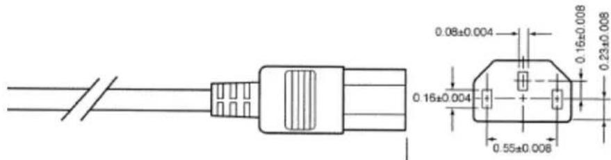
Figure 15. AC Power Cord
3.1.4 AC Input Requirement
3.1.4.1 Power Factor
The PF shall align with server energy star 2.0 requirements. Power supplies must meet the minimum power factor requirements presented in the table below, for all loading conditions where the output power is greater than or equal to 75 watts.
Table 6. Power Factor
| Output power | 20% load | 50% load | 100% load |
| Power factor | 0.8 | 0.9 | 0.98 |
3.1.4.2 AC Input Voltage Specification
The power module shall operate over the range and limits shown in the following table.
Table 7. AC Input Voltage Range
| PARAMETER | MIN | RATED | MAX | Max Input AC Current |
| Line Voltage (110) | 90 Vrms | 100-127 Vrms | 140 Vrms | 6 Arms1 |
| Line Voltage (220) | 180 Vrms | 200-240 Vrms | 264 Vrms | 3 Arms2 |
| Frequency | 47 Hz | 50/60 Hz | 63 Hz |
Notes:
- Maximum input current at low input voltage range shall be measured at 90VAC, at maximum load.
- Maximum input current at high input voltage range shall be measured at 180VAC, at maximum load.
- This requirement is not to be used for determining agency input current markings.
3.1.4.3 AC Line Isolation Requirements
The power supply shall meet all safety agency requirements for dielectric strength. Additionally, power supply vendor must provide Intel with written confirmation of dielectric withstand test which includes voltage level, duration of test, and identification detailing how each power supply is marked to indicate that the dielectric withstand test is completed successfully. Transformers' isolation between primary and secondary windings must comply with the 3000Vac (4242VDC)
dielectric strength criteria. If the working voltage between primary and secondary dictates a higher dielectric strength test voltage, the highest test voltage should be used. In addition, the insulation system must comply with reinforced insulation as per safety standard IEC 950. Separation between the primary and secondary circuits, and primary to ground circuits, must comply with the IEC 950 spacing requirements.
3.1.4.4 AC Line Dropout/Holdup
An AC line dropout is defined when the AC input drops to 0VAC at any phase angle of the nominal AC line voltage. An AC line dropout less than 12ms shall not cause any tripping of control signals or protection circuits for 350W output. If the AC line dropout over 12ms, the power supply should recover back to normal operation and meet all turn on requirements. Any dropout of the AC line shall not cause damage to the power supply.
3.1.4.5 AC Line Fuse
The power supply should have one line fused in the single line fuse on the line (Hot) wire of the AC input. The line fusing must be acceptable for all safety agency requirements. The input fuse should be a slow blow type. AC inrush current must not cause the AC line fuse to blow under any conditions. All protection circuits in the power supply should not cause the AC fuse to blow unless a component in the power supply has failed. This includes DC output load short conditions.
3.1.4.6 AC Inrush
The peak inrush current must not damage the PSU, or the input fuse must not blow under any conditions of load, temperature, and input voltage, including repeated, rapid cycling of the power line. Half cycle peak inrush current, peak repetitive input current, and worse case power factor must be provided by the vendor to assist with the UPS and line conditioning, sizing, and selection. No component will be stressed over its maximum specification. This must be demonstrated through measurements of the critical component specifications. The peak inrush current shall be less than 55A peak at 115VAC input and 230VAC input, cold start and 25°C.
3.1.4.7 AC Line Leakage Current
The maximum leakage current to ground shall be less than 1.0mA-rms at 240Vac, 50Hz.
3.1.4.8 AC Line Transient Specification
The AC line transient conditions are defined as sag and surge conditions. Sag conditions are also commonly referred to as “brownout”. Sag conditions are defined as the conditions when the AC line voltage drops below nominal voltage. Surge conditions are defined as the conditions when the AC line voltage rises above nominal voltage.
The power supply must meet the requirements under the following AC line sag and surge conditions.
Table 8. AC Line Sag Transient Performance
| AC Line Sag (10sec interval between each sagging) | ||||
| Duration | Sag | Operating AC Voltage | Line Frequency | Performance Criteria |
| Continuous | 10% | Nominal AC Voltage ranges | 50/60Hz | No loss of function or performance |
| 1 to 12ms | 100% | Nominal AC Voltage ranges | 50/60Hz | No loss of function or performance |
| >12ms | >30% | Nominal AC Voltage ranges | 50/60Hz | Loss of function acceptable, self recoverable |
Table 9. AC Line Surge Transient Performance
| AC Line Surge | ||||
| Duration | Surge | Operating AC Voltage | Line Frequency | Performance Criteria |
| Continuous | 10% | Nominal AC Voltages | 50/60Hz | No loss of function or performance |
| 0 to 1⁄2 AC cycle | 30% | Nominal AC Voltages | 50/60Hz | No loss of function or performance |
3.1.4.9 Susceptibility Requirements
The power supply shall meet the following electrical immunity requirements when connected to a cage with an external EMI filter which meets the criteria defined in the SSI document EPS Power Supply Specification. For further information on Intel standards, request a copy of the Intel® Environmental Standards Handbook.
Table 10. Performance Criteria
| Level | Description |
| A | The apparatus shall continue to operate as intended. No degradation of performance. |
| B | The apparatus shall continue to operate as intended. No degradation of performance beyond spec limits. |
| C | Temporary loss of function is allowed provided the function is self-recoverable or can be restored by the operation of the controls. |
3.1.4.10 Electrostatic Discharge Susceptibility
The power supply shall comply with the limits defined in EN 55024: 1998 using the IEC 61000-4-2:1995 test standard and performance criteria B defined in Annex B of CISPR 24.
AIR DISCHARGE ±8kV CONTACT DISCHARGE ±4kV
3.1.4.11 Fast Transient/Burst
The power supply shall comply with the limits defined in EN55024: 1998/A1: 2001/A2: 2003 using the IEC 61000-4-4: Second edition: 2004-07 test standard and performance criteria B defined in Annex B of CISPR 24.
3.1.4.12 Radiated Immunity
The power supply shall comply with the limits defined in EN55024: 1998/A1: 2001/A2: 2003 using the IEC 61000-4-3: Edition 2.1: 2002-09 test standard and performance criteria A defined in Annex B of CISPR 24.
3.1.4.13 Surge Immunity
The power supply shall be tested with the system for immunity to AC Ring Wave and AC Unidirectional Wave, both up to 2kV. The power supply shall operate normally without any component damage under any condition.
BI-WAVE 12 Ω ±2.0kV (Common mode)
2 Ω ± 1.0kV (Differential mode)
RING-WAVE 500A±2.0kV (Common mode)
500A±1.0kV (Differential mode)
3.1.4.14 Power Recovery
The power supply should recover automatically after an AC power failure. AC power failure is defined as any loss of AC power that exceeds the dropout criteria.
3.1.4.15 Voltage Interruptions
The power supply shall comply with the limits defined in EN55024: 1998/A1: 2001/A2: 2003 using the IEC 61000-4-11: Second Edition: 2004-03 test standard and performance criteria C defined in Annex B of CISPR 24.
3.1.5 DC Output Specification
3.1.5.1 Output Power/Currents
The following table defines the output power and current ratings.
Table 11. Output Current Requirements
| Output | Minimum | Maximum | Output Power |
| +3.3V | 0.1A | 10A | 33W |
| +5V | 0.1A | 16A | 80W |
| +12V1 | 0.75A | 18A | 216W |
| +12V2 | 0.75A | 18A | 216W |
| -12V | 0.0A | 0.5A | 6W |
| +5VSB | 0.05A | 2.5A | 12.5W |
Notes:
- The total current of +12V1/2 will not exceed 28A.
- The total output for this PSU is 350W.
- The total output of +3.3V & +5V will not exceed 100W.
3.1.5.2 Standby Output
The 5VSB output should be present when an AC input greater than the power supply turn on voltage is applied.
3.1.6 Protection Circuits
The protection circuits inside the power supply should cause only the power supply's main outputs to shut down. If the power supply latches off due to a protection circuit tripping, an AC
cycle OFF for 15sec (with +5VSB/0.1A) and a PSON ^# cycle HIGH for one second shall be able to reset the power supply.
3.1.6.1 Over Current Protection (OCP)
Each output shall have individual OCP protection circuits. The PSU shall shut down and latch off after an over current condition occurs. Whereas OCP of +5VSB shall turn the power supply into "hiccup mode" until the OCP condition is removed. The values are measured at the PSU harness connectors and shall not be damaged from repeated power cycling in this condition. There shall be current sensors and limit circuits to shut down the entire power supply if the limit is exceeded. The limits are listed below.
Table 12. Over Load Protection (OCP) Limits
| Output Voltage | Continuous Load | |
| Current Limit MIN | Current Limit MAX | |
| +12V1 | 18.2A | 20A |
| +12V2 | 18.2A | 20A |
| +5V | 19.2A | 24A |
| +3.3V | 12A | 15A |
| -12V | 4A | |
| +5VSB | 4.5A | |
3.1.6.2 Over Voltage Protection (OVP)
Each output shall have individual OVP protection circuits built in and it shall be locally sensed. The PSU shall shut down and latch off after an over voltage condition occurs. The output voltages are measured at the harness connectors. The voltage shall never exceed the maximum levels when measured at the power pins of the output harness connector during any single point of fail. The voltage shall never trip any lower than the minimum levels when measured at the power pins of the connector.
Table 13. Over Voltage Protection (OVP) Limits
| Output Voltage | OVP MIN (V) | OVP MAX (V) |
| +3.3V | 3.7 | 4.5 |
| +5V | 5.7 | 6.5 |
| +12V1/+12V2 | 13.3 | 15.6 |
| -12V | -13.3 | -15.6 |
| +5VSB | 5.7 | 6.5 |
3.1.6.3 Over Temperature Protection (OTP)
The power supply shall be protected against over temperature conditions caused by loss of fan cooling or excessive ambient temperature. In an OTP condition the PSU will shut down. When the power supply temperature drops to within specified limits, the power supply shall restore power automatically, while the +5VSB remains always on. The OTP trip level shall have a minimum of 4^ C of ambient temperature hysteresis, so that the power supply will not oscillate on and off due to temperature recovery condition.
3.2 450W mini-ERPS Redundant Power Supply
The 450W 1+1 redundant power supply has two outputs: +12V DC and +5V Standby. There is one Power Distribution Board (PDB) for 450W AC 1+1 redundant power supply. The PDB is
designed to plug directly to the output connector of the power supply and it contains two DC/DC power converters to produce other required voltages: +3.3V and +5V. The PDB is integrated in the power supply cage.
3.2.1 Mechanical Overview
The following drawing is the cage which integrates the power supply units and the PDB.
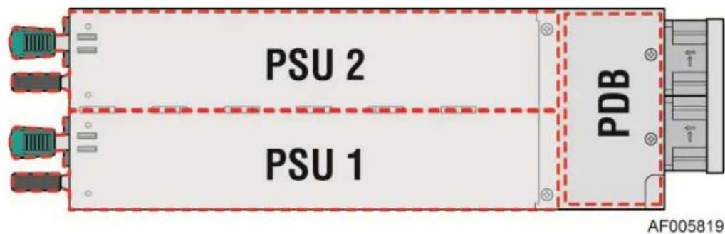
Figure 16. 450W AC PSU with PDB
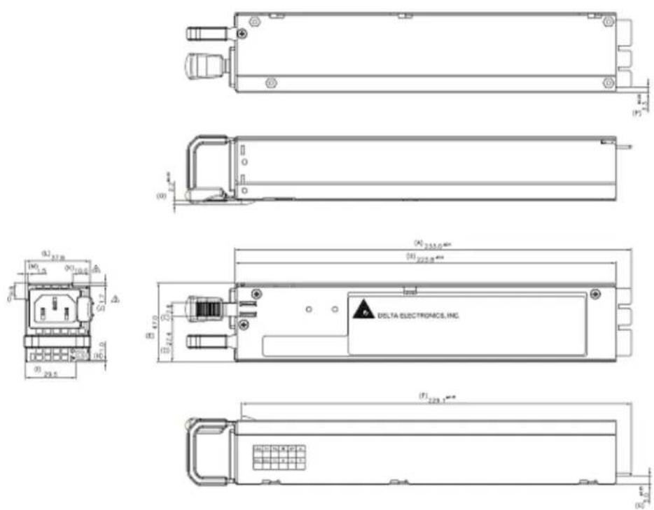
Figure 17. 450W AC Power Supply Unit Dimension Overview
natural_image
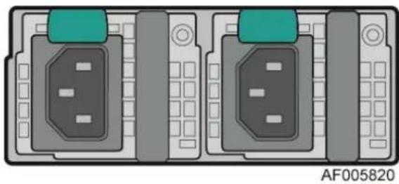
Diagram of two identical electronic device ports with control knobs and indicator lights (no text or symbols)Figure 18. 450W AC Power Supply – Connector View
3.2.2 Power Supply Module Card Edge Connector
This 450W AC power supply module has 2x14 card edge output connection that plugs directly into a matching slot connector on power distribution board. The connector provides both power and communication signals.
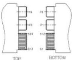
Figure 19. 450W Power Supply Module Output Power Connector
The following table defines the connector pin-out.
Table 14. 450W Power Supply Module Output Power Connector Pin-out
| Pin | Definition | Pin | Definition |
| S1 | NA | S2 | NA |
| S3 | L_MON | S4 | ALERT |
| S5 | SDA | S6 | SCL |
| S7 | PS_KILL | S8 | PSON |
| S9 | PSOK | S10 | SGND |
| S11 | +5VSB | S12 | +5VSB |
| S13 | FAN_PLSE2 | S14 | PRESENT |
| S15 | AO | S16 | VCC2 |
| S17 | FAN_GND | S18 | FAN_PWR |
| S19 | FAN_PLSE | S20 | FAN_VS |
| S21 | RS+ | S22 | RS- |
| S23 | +5VSB | S24 | +5VSB |
| P1 | +12V | P2 | +12V |
| P3 | SGND | P4 | SGND |
3.2.3 Power Supply Module Efficiency
The following table provides the required minimum efficiency level at various loading conditions. These are provided at three different load levels: 100%, 50%, and 20%.
Table 15. 450WAC Power Supply Efficiency
| Loading | 100% of maximum | 50% of maximum | 20% of maximum |
| Minimum Efficiency | 88% | 92% | 88% |
3.2.4 Power Cord Specification Requirements
The power cords used must meet the specification requirements listed in the following table.
Table 16. AC Power Cord Specifications
| Cable Type | SJT |
| Wire Size | 16 AWG |
| Temperature Rating | 105°C |
| Amperage Rating | 13 A |
| Voltage Rating | 125 V |
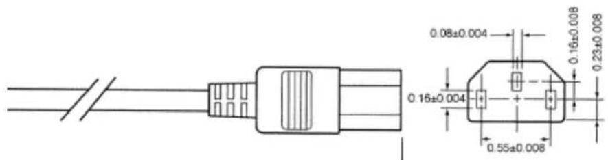
Figure 20. AC Power Cord
3.2.5 AC Input Requirement
3.2.5.1 Power Factor
The power supply must meet the power factor requirements stated in the Energy Star® Program Requirements for Computer Servers. These requirements are stated below.
| Output power | 20% load | 50% load | 100% load |
| Power factor | 0.8 | 0.9 | 0.95 |
Tested at 230VAC, 50Hz and 60Hz; and 115VAC, 60Hz.
3.2.5.2 AC Input Voltage Specification
The power supply must operate within all specified limits over the following input voltage range. Harmonic distortion of up to 10% of the rated line voltage must not cause the power supply to go out of specified limits. Application of an input voltage below 85VAC should not cause damage to the power supply, including a blown fuse.
Table 17. AC Input Voltage Range
| PARAMETER | MIN | RATED | VMAX | Start up VAC | Power Off VAC |
| Voltage (110) | 90 Vrms | 100-127 Vrms | 140 Vrms | 85VAC +/- 4VAC | 70VAC +/- 5VAC |
| Voltage (220) | 180 Vrms | 200-240 Vrms | 264 Vrms | ||
| Frequency | 47 Hz | 50/60 | 63 Hz |
Notes:
-
Maximum input current at low input voltage range shall be measured at 90VAC, at maximum load.
-
Maximum input current at high input voltage range shall be measured at 180VAC, at maximum load.
-
This requirement is not to be used for determining agency input current markings.
3.2.5.3 AC Line Isolation Requirements
The power supply shall meet all safety agency requirements for dielectric strength. Additionally, power supply vendor must provide Intel with written confirmation of dielectric withstand test which includes voltage level, duration of test, and identification detailing how each power supply is marked to indicate that the dielectric withstand test is completed successfully. Transformers' isolation between primary and secondary windings must comply with the 3000VAC (4242VDC) dielectric strength criteria. If the working voltage between primary and secondary dictates a higher dielectric strength test voltage, the highest test voltage should be used. In addition, the insulation system must comply with reinforced insulation as per safety standard IEC 950. Separation between the primary and secondary circuits, and primary to ground circuits, must comply with the IEC 950 spacing requirements.
3.2.5.4 AC Line Dropout/Holdup
An AC line dropout is defined to be when the AC input drops to 0VAC at any phase of the AC line for any length of time. During an AC dropout, the power supply must meet dynamic voltage regulation requirements. An AC line dropout of any duration should not cause tripping of control signals or protection circuits. If the AC dropout lasts longer than the holdup time, the power supply should recover and meet all turn on requirements. The power supply should meet the AC dropout requirement over rated AC voltages and frequencies. A dropout of the AC line for any duration should not cause damage to the power supply.
| Loading | Holdup time |
| 75% | 12msec |
| 100% | 10msec |
3.2.5.5 AC Line Fuse
The power supply should have one line fused in the single line fuse on the line (Hot) wire of the AC input. The line fusing must be acceptable for all safety agency requirements. The input fuse should be a slow blow type. AC inrush current must not cause the AC line fuse to blow under any conditions. All protection circuits in the power supply should not cause the AC fuse to blow unless a component in the power supply has failed. This includes DC output load short conditions.
3.2.5.6 AC Inrush
The peak inrush current must not damage the PSU, or the input fuse must not blow under any conditions of load, temperature, and input voltage, including repeated, rapid cycling of the power line. Half cycle peak inrush current, peak repetitive input current, and worse case power factor must be provided by the vendor to assist with the UPS and line conditioning, sizing, and selection. No component will be stressed over its maximum specification (I 2·t). This must be demonstrated through measurements of the critical component specifications.
3.2.5.7 AC Line Leakage Current
The maximum leakage current to ground for each power supply shall be 3.5mA when tested at 240VAC.
3.2.5.8 AC Line Transient Specification
The AC line transient conditions are defined as sag and surge conditions. Sag conditions are also commonly referred to as “brownout”. Sag conditions are defined as the conditions when the AC line voltage drops below nominal voltage. Surge conditions are defined as the conditions when the AC line voltage rises above nominal voltage.
The power supply must meet the requirements under the following AC line sag and surge conditions.
Table 18. AC Line Sag Transient Performance
| AC Line Sag (10sec interval between each sagging) | ||||
| Duration | Sag | Operating AC Voltage | Line Frequency | Performance Criteria |
| 0 to 1/2 AC cycle | 95% | Nominal AC Voltage ranges | 50/60Hz | No loss of function or performance |
| >1 AC cycle | >30% | Nominal AC Voltage ranges | 50/60Hz | Loss of function acceptable, self recoverable |
Table 19. AC Line Surge Transient Performance
| AC Line Surge | ||||
| Duration | Surge | Operating AC Voltage | Line Frequency | Performance Criteria |
| Continuous | 10% | Nominal AC Voltages | 50/60Hz | No loss of function or performance |
| 0 to 1⁄2 AC cycle | 30% | Mid-point of nominal AC Voltages | 50/60Hz | No loss of function or performance |
3.2.5.9 Susceptibility Requirements
The power supply shall meet the following electrical immunity requirements when connected to a cage with an external EMI filter which meets the criteria defined in the SSI document EPS Power Supply Specification. For further information on Intel standards, request a copy of the Intel® Environmental Standards Handbook.
Table 20. Performance Criteria
| Level | Description |
| A | The apparatus shall continue to operate as intended. No degradation of performance. |
| B | The apparatus shall continue to operate as intended. No degradation of performance beyond spec limits. |
| C | Temporary loss of function is allowed provided the function is self-recoverable or can be restored by the operation of the controls. |
3.2.5.10 Electrostatic Discharge Susceptibility
The power supply shall comply with the limits defined in EN 55024: 1998/A1: 2001/A2: 2003 using the IEC 61000-4-2: Edition 1.2: 2001-04 test standard and performance criteria B defined in Annex B of CISPR 24.
3.2.5.11 Fast Transient/Burst
The power supply shall comply with the limits defined in EN55024: 1998/A1: 2001/A2: 2003 using the IEC 61000-4-4: Second edition: 2004-07 test standard and performance criteria B defined in Annex B of CISPR 24.
3.2.5.12 Radiated Immunity
The power supply shall comply with the limits defined in EN55024: 1998/A1: 2001/A2: 2003 using the IEC 61000-4-3: Edition 2.1: 2002-09 test standard and performance criteria A defined in Annex B of CISPR 24.
3.2.5.13 Surge Immunity
The power supply shall be tested with the system for immunity to AC Unidirectional Wave; 2kV line to ground and 1kV line to line, per EN 55024: 1998/A1: 2001/A2: 2003, EN 61000-4-5: Edition 1.1:2001-04.
The pass criteria include:
- No unsafe operation is allowed under any condition.
- All power supply output voltage levels to stay within proper spec levels.
- No change in operating state or loss of data during and after the test profile.
- No component damage under any condition.
The power supply shall comply with the limits defined in EN55024: 1998/A1: 2001/A2: 2003 using the IEC 61000-4-5: Edition 1.1:2001-04 test standard and performance criteria B defined in Annex B of CISPR 24.
3.2.5.14 Power Recovery
The power supply should recover automatically after an AC power failure. AC power failure is defined as any loss of AC power that exceeds the dropout criteria.
3.2.5.15 Voltage Interruptions
The power supply shall comply with the limits defined in EN55024: 1998/A1: 2001/A2: 2003 using the IEC 61000-4-11: Second Edition: 2004-03 test standard and performance criteria C defined in Annex B of CISPR 24.
3.2.6 DC Output Specification
3.2.6.1 Output Power/Currents
The following table defines the output current ratings. Each output has a maximum and minimum current rating shown in Table 21. The power supply shall meet both static and dynamic voltage regulation requirements for the minimum dynamic load conditions. The power supply must meet only the static load voltage regulation requirements for the minimum static load conditions.
Table 21. Load Ratings
| +12V | +5VSB | |
| MAX | 36.26A | 3A |
| MIN DYNAMIC | 2A | 0.5A |
| MIN STATIC | 0.5A | 0.1A |
The combined output power of all outputs shall not exceed 405W @100\~127VAC.
3.2.6.2 Standby Output
The 5VSB output should be present when an AC input greater than the power supply turn on voltage is applied.
3.2.7 Protection Circuits
The protection circuits inside the power supply should cause only the power supply's main outputs to shut down. If the power supply latches off due to a protection circuit tripping, an AC cycle OFF for 15sec and a PSON# cycle HIGH for 1sec shall be able to reset the power supply.
3.2.7.1 Current Limit (OCP)
The following are the over current protection limits for each output. For testing purposes, the overload currents of each tested output rail should be ramped at a minimum rate of 10 A/sec starting from full load. If the current limits are exceeded, the power supply should shut down and latch off. The latch will be cleared by toggling the PSON# signal or by an AC power interruption. The power supply should not be damaged from repeated power cycling in this condition. 5VSB must be protected under over current or shorted conditions, so that no damage can occur to the power supply. 5VSB will be auto-recovered after OCP limit is removed.
Table 22. Over Current Limits
| Output | Min OCP | Max OCP |
| +12V | 40 A | 54 A |
| 5Vstby | 3.6A~8A | |
3.2.7.2 Over Voltage Protection (OVP)
The power supply over voltage protection should be locally sensed. The power supply must shut down and latch off after an over voltage condition occurs. This latch shall be cleared by toggling the PSON# signal or by an AC power interruption. The following table contains the over voltage limits. The values are measured at the output of the power supply pins. The voltage should never exceed the maximum levels when measured at the power pins of the power supply connector during any single point of fail. The voltage should never trip any lower than the minimum levels when measured at the power pins of the power supply connector. 5VSB will be auto-recovered after the OVP limit is removed.
Table 23. Over Voltage Protection (OVP) Limits
| OUTPUT VOLTAGE | PROTECTION POINT [V] |
| +12 V | 13.6V ~ 15.0V |
| 5VSB | 5.6V ~ 6.5V |
3.2.7.3 Over Temperature Protection (OTP)
The power supply will be protected against over temperature conditions caused by loss of fan cooling or excessive ambient temperature. In an OTP condition, the PSU will shut down. When the power supply temperature drops to within specified limits, the power supply will restore power automatically, while the 12VSB remains always on. The OTP circuit must have a built in margin, so that the power supply will not oscillate ON and OFF due to the temperature recovering condition. The OTP trip level should have a minimum of 4^ C of ambient temperature margin.
4 Thermal Management
The fully integrated system is designed to operate at external ambient temperatures of between 10^ C and 35^ C with limited excursion based operation up to 35^ C. Working with integrated platform management, several features within the system are designed to move air in a front to back direction, through the system and over critical components in order to prevent them from overheating and allow the system to operate with best performance.
The Intel ^® Server System R1000RP product family supports short-term, excursion-based, operation up to 35°C (ASHRAE A2) with limited performance impact. The configuration requirements and limitations are described in the configuration matrix found in the Intel ^® S1200V3RP Product Family Power Budget and Thermal Configuration Tool, available to download online at http://www.intel.com/p/en_US/support.
The installation and functionality of several system components are used to maintain system thermals.
4.1 Thermal Operation and Configuration Requirements
To keep the system operating within supported maximum thermal limits, the system must meet the following operating and configuration guidelines:
- The system operating ambient is designed for sustained operation up to 35° C (ASHRAE Class A2).
- When operating within the extended operating temperature range, the system performance may be impacted.
There is no long term system reliability impact when operating at the extended temperature range within the approved limits.
- Specific configuration requirements and limitations are documented in the configuration matrix found in the Intel® Server Board S1200V3RP product family Power Budget and Thermal Configuration Guidelines Tool, available to download online at http://www.intel.com/p/en_US/support.
- The processor and the CPU heatsink must be installed first.
■ Memory Slot population requirements
Note: Specified memory slots can be populated with a DIMM or supplied DIMM Blank. Memory population rules apply when installing DIMMs. Install DIMMs in the order; Channels A, then Channels B. Start with the first DIMM (Blue Slot) on each channel, then slot 2. Only remove factory installed DIMM blanks when populating the slot with an actual memory module.
- All hard drive bays must be populated. Hard drive carriers can be populated with a hard drive or supplied drive blank.
- In single power supply configurations, the second power supply bay must have the supplied filler blank installed at all times.
- The system top-cover must be installed at all times.
4.2 Thermal Management Overview
In order to maintain the necessary airflow within the system, all of the previously listed components and top cover need to be properly installed. For best system performance, the external ambient temperature should remain below 35^ C and all system fans should be operational. The system is designed for fan redundancy when the system is configured with two power supplies. If a single system fan fails (System fan or Power Supply Fan), integrated platform management will change the state of the System Status LED to flashing Green, report an error to the system event log, and automatically adjust fan speeds as needed to maintain system temperatures below maximum thermal limits.
Note: All system fans are controlled independently of each other. The fan control system may adjust fan speeds for different fans based on increasing/decreasing temperatures in different thermal zones within the chassis.
In the event that system thermals should continue to increase with the system fans operating at their maximum speed, platform management may begin to throttle bandwidth of either the memory subsystem or the processors or both, in order to keep components from overheating and keep the system operational. Throttling of these subsystems will continue until system thermals are reduced below preprogrammed limits.
If system temperatures increase to a point beyond the maximum thermal limits, the system will shut down, the System Status LED will change to a solid Amber state, and the event will be logged to the system event log.
Note: Sensor data records (SDRs) for any given system configuration must be loaded by the system integrator for proper thermal management of the system. SDRs are loaded using the FRUSDR utility.
An intelligent Fan Speed Control (FSC) and thermal management technology (mechanism) is used to maintain comprehensive thermal protection, deliver the best system acoustics, and improves fan power efficiency. Options in
4.2.1 Set Throttling Mode
This option is used to select the desired memory thermal throttling mechanism. Available settings include [Auto], [CLTM], and [OLTM].
[Auto] – Factory Default Setting: BIOS automatically detects and identifies the appropriate thermal throttling mechanism based on the DIMM type, airflow input, and DIMM sensor availability.
[CLTM] – Closed Loop Thermal Management: Would be used with an OEM chassis and DIMMs with TSOD. The firmware does not change the offset registers for closed loop during runtime, although the Management Engine can do so.
[OLTM] – Open Loop Thermal Management: Is intended for a system with UDIMMs which do not have TSOD. The thermal control registers are configured during POST, and the firmware
does not change them.
4.2.2 Altitude
This option is used to select the proper altitude that the system will be used in. Available settings include [300m or less], [301m-900m], [901m-1500m], and [Above 1500m].
Selecting an altitude range that is lower than the actual altitude the system will be operating at, can cause the fan control system to operate less efficiently, leading to higher system thermals and lower system performance. If the altitude range selected is higher than the actual altitude the system will be operating at, the fan control system may provide better cooling but with higher acoustics and higher fan power consumption. If the altitude is not known, selecting a higher altitude is recommended in order to provide sufficient cooling.
4.2.3 Set Fan Profile
This option is used to set the desired Fan Profile. Available settings include [Performance] and [Acoustic].
The Acoustic mode offers the best acoustic experience and appropriate cooling capability supporting the majority of the add-in cards used. Performance mode is designed to provide sufficient cooling capability covering all kinds of add-in cards on the market.
4.2.4 Fan PWM Offset
This option is reserved for manual adjustment to the minimum fan speed curves. The valid range is from [0 to 100] which stands for 0% to 100% PWM adding to the minimum fan speed. This feature is valid when Quiet Fan Idle Mode is at Enabled state. The default setting is [0].
4.2.5 Quiet Fan Idle Mode
This feature can be [Enabled] or [Disabled]. If enabled, the fans will either shift to a lower speed or stop when the aggregate sensor temperatures are satisfied, indicating the system is at ideal thermal/light loading conditions. When the aggregate sensor temperatures are not satisfied, the fans will shift back to normal control curves. If disabled, the fans will never shift into lower fan speeds or stop, regardless of whether the aggregate sensor temperatures are satisfied. The default setting is [Disabled].
Note: The above feature may or may not be in effect and depends on the actual thermal characteristics of the specified system.
4.2.6 Thermal Sensor Input for Fan Speed Control
The BMC uses various IPMI sensors as inputs to control fan speed. Some of the sensors are actual physical sensors and some are virtual sensors derived from calculations.
The following IPMI thermal sensors are used as input to control fan speed:
■ Front Panel Temperature Sensor 1
■ CPU Margin Sensors 2, 4, 5
■ DIMM Thermal Margin Sensors 2,4
■ PCH Temperature Sensor 3,5
Intel ^® Server System R1000RP Family TPS Thermal Management
■ On-board Ethernet Controller Temperature Sensors 3,5
- Add-In Intel ^ SAS/IO Module Temperature Sensors ^3,5
■ PSU Thermal Sensor 3,8
■ CPU VR Temperature Sensors 3,6
■ DIMM VR Temperature Sensors 3,6
■ BMC Temperature Sensor 3.6
■ Global Aggregate Thermal Margin Sensors 7
- I/O module Temperature Sensor (With option installed)
Intel ^® ROC Module (With option installed)
Notes:
- For fan speed control in Intel ^® chassis
- Temperature margin from throttling threshold
- Absolute temperature
- PECI value or margin value
- On-die sensor
- On-board sensor
- Virtual sensor
- Available only when PSU has PMBus*
- Calculated estimate
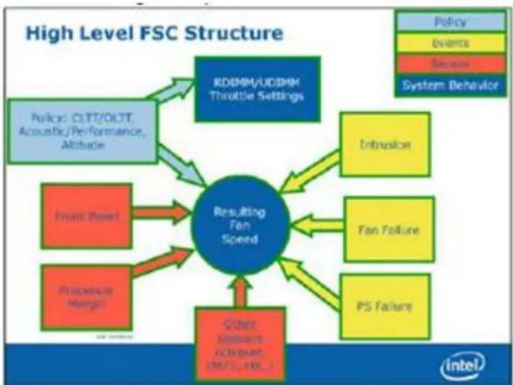
The following diagram illustrates the fan speed control structure.
flowchart
graph TD
    A["Policy"] --> B["RD/MM/UD/MM Throttle Settings"]
    C["Events"] --> D["Intrusion"]
    E["Sensor"] --> F["Fan Failure"]
    G["System Behavior"] --> H["PS Failure"]
    I["Other Sensors (EC/SNAT, 2017), 100.1"] --> J["Resulting Fan Speed"]
    K["Front Panel"] --> J
    L["Procurement Manager"] --> J
    M["Action Panel"] --> J
    N["Intrusion"] --> J
    O["Fan Failure"] --> J
    P["PS Failure"] --> J
Figure 21. Fan Control Model
4.3 System Fans
Two managed dual rotor 40mm x 56mm system fans and one 40mm x 40 mm system fan provide the primary airflow for the system.
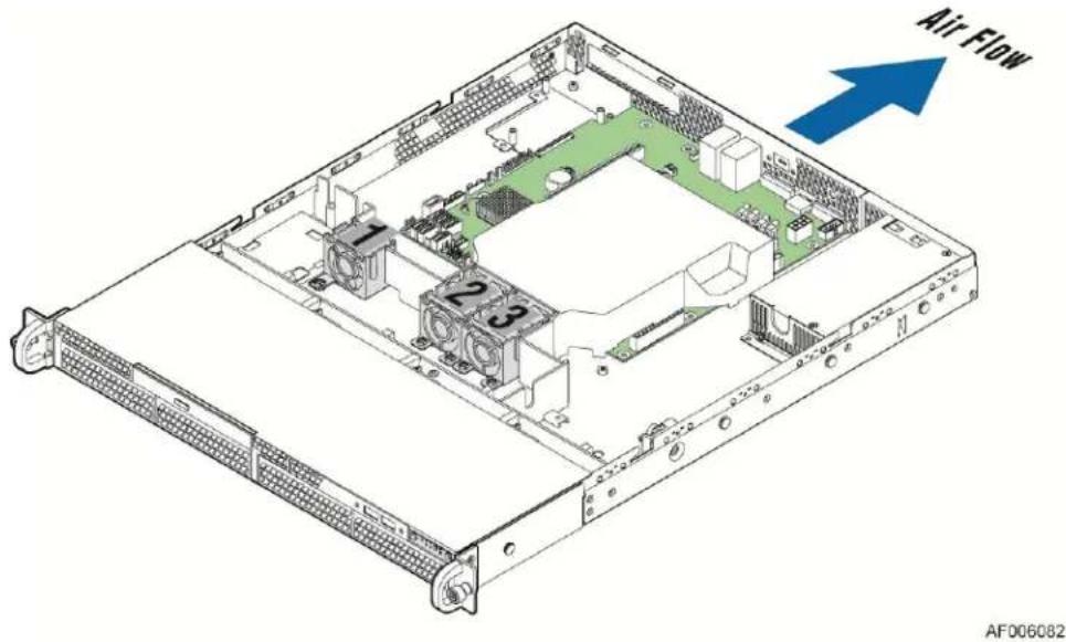
Figure 22. System Fan Identification
Each system fan is mounted inside its own plastic fan housing which includes rotational vibration dampening features. The fan assemblies are held in place by fitting them over mounting pins coming up from the chassis base.
natural_image
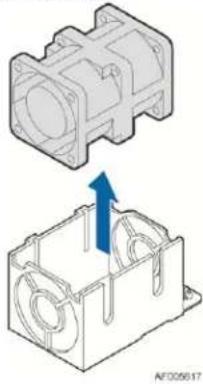
Technical illustration of a mechanical component with an arrow indicating assembly or force direction (no text or symbols present)Figure 23. Removing a System Fan
The system fan assembly is designed for ease of use and supports several features.
System fans are not hot-swappable.
Each fan and fan assembly is designed for tool-less insertion and extraction from the system. For instructions on fan replacement, see the Intel® Server System R1000RP Service Guide.
Fan speed for each fan is controlled by integrated platform management as controlled by the integrated BMC on the server board. As system thermals fluctuate high and low, the integrated BMC firmware will increase and decrease the speeds to specific fans to regulate system thermals.
Each fan has a tachometer signal that allows the integrated BMC to monitor its status.
Each fan has a 4-pin wire harness that connects to a matching connector on the server board.
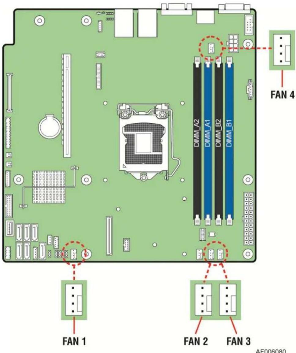
Figure 24. Server Board System Fan Connector Locations
Table 24. System Fan Connector Pin-out
| Pin | Signal Name | Type | Description |
| 1 | Ground | GND | Ground is the power supply ground. |
| 2 | 12V | Power | Power supply 12 V. |
| 3 | Fan Tach | In | FAN_TACH signal is connected to the BMC to monitor the fan speed. |
| 4 | Fan PWM | Out | FAN_PWM signal to control fan speed. |
4.4 FRUSDR Utility
The purpose of the embedded platform management and fan control systems is to monitor and control various system features, and to maintain an efficient operating environment. Platform management is also used to communicate system health to supported platform management software and support mechanisms. The FRUSDR utility is used to program the server board with platform specific environmental limits, configuration data, and the appropriate sensor data records (SDRs), for use by these management features.
The FRUSDR utility must be run as part of the initial platform integration process before it is deployed into a live operating environment. It must be run with the system fully configured and each time the system configuration changes.
The FRUSDR utility for the given server platform can be run as part of the Intel ^® Server Deployment Toolkit and Management DVD that ships with each Intel ^® server, or can be downloaded from http://www.intel.com/p/en_US/support.
Note: The embedded platform management system may not operate as expected if the platform is not updated with accurate system configuration data. The FRUSDR utility must be run with the system fully configured and each time the system configuration changes, for accurate system monitoring and event reporting.
5 System Storage and Peripheral Options
The Intel ^® Server System R1000RP product family has support for many storage device options, including:
- Hot Swap 2.5" Hard Disk Drives
- Hot Swap 3.5" Hard Disk Drives
■ SATA Optical Drive
Support for different storage and peripheral device options will vary depending on the system SKU. This section provides an overview of each available option.
5.1 2.5" Hard Disk Drive Support
The server is available with support for eight 2.5" hard disk drives as illustrated below.

Figure 25. 2.5" Hard Drive Bay Drive Configuration
The drive bay can support either SATA or SAS hard disk drives. Mixing of drive types within the hard drive bay is not supported. Hard disk drive type is dependent on the type of host bus controller used, SATA only or SAS. Each 2.5" hard disk drive is mounted to a drive carrier, allowing for hot swap extraction and insertion. Drive carriers have a latching mechanism that is used to extract and insert drives from the chassis, and lock the tray in place.
Light pipes integrated into the drive tray assembly direct the light emitted from Amber drive status and Green activity LEDs located next to each drive connector on the backplane, to the drive tray faceplate, making them visible from the front of the system.

Figure 26. LED of HDD Carrier
Table 25. Drive Status LED States
| Amber | Off | No access and no fault |
| Solid On | Hard Drive Fault has occurred | |
| Blink | RAID rebuild in progress (1 Hz), Identify (2 Hz) |
Table 26. Drive Activity LED States
| Green | Condition | Drive Type | Behavior |
| Power on with no drive activity | SAS | LED stays on | |
| SATA | LED stays off | ||
| Power on with drive activity | SAS | LED blinks off when processing a command | |
| SATA | LED blinks on when processing a command | ||
| Power on and drive spun down | SAS | LED stays off | |
| SATA | LED stays off | ||
| Power on and drive spinning up | SAS | LED blinks | |
| SATA | LED stays off |
5.1.1 2.5" Drive Hot-Swap Backplane Overview

natural_image
Pure mechanical component diagram without any text, numbers, or symbolsFigure 27. The Front Side of 8 X 2.5" Hot Swap Backplane
On the backside of each backplane are several connectors. The following illustration identifies each connector.

| Label | Description |
| A | Power connector |
| B | 4-port Mini-SAS cable connectors |
| C | SMBus*-In cable connector – From Server board |
Figure 28. The Back Side of 8 X 2.5" Hot Swap Backplane
A – Power Harness Connector: The backplane includes a 2x2 connector supplying power to the backplane. Power is routed to the backplane through a power cable harness from the server board.
B – Multi-port Mini-SAS Cable Connectors: The backplane includes two multi-port mini-SAS cable connectors, each providing I/O signals for four SAS/SATA hard drives on the backplane. Cables can be routed from matching connectors on the server board, add-in SAS/SATA RAID cards, or optionally installed SAS expander cards.
C – SMBus* Cable Connectors: The backplane includes a 1x5 cable connector used as a management interface to the server board.
5.1.2 Cypress\* CY8C22545 Enclosure Management Controller
The backplane supports enclosure management using a Cypress* CY8C22545 Programmable System-on-Chip (PSoC*) device. The CY8C22545 drives the hard drive activity/fault LED, hard drive present signal, and controls hard drive power-up during system power-on.
5.2 3.5" Hard Disk Drive Support
The server is available with support for four 3.5" hard disk drives as illustrated below.

Figure 29. 3.5" Hard Drive Bay Configuration
The drive bay can support either SATA or SAS hard disk drives. Mixing of drive types within the hard drive bay is not supported. Hard disk drive type is dependent on the type of host bus controller used, SATA only or SAS. Each 3.5" hard disk drive is mounted to a drive tray, allowing for hot swap extraction and insertion. Drive trays have a latching mechanism that is used to extract and insert drives from the chassis, and lock the tray in place.
The hard drive carrier can also support 2.5" SSD. (Note: It is suggested not to use the 2.5" hard drive in the 3.5" carrier). Light pipes integrated into the drive tray assembly direct the light emitted from Amber drive status and Green activity LEDs located next to each drive connector on the backplane, to the drive tray faceplate, making them visible from the front of the system.

| Amber | Off | No access and no fault |
| Solid On | Hard Drive Fault has occurred | |
| Blink | RAID rebuild in progress (1 Hz), Identify (2 Hz) |
| Green | Condition | Drive Type | Behavior |
| Power on with no drive activity | SAS | LED stays on | |
| SATA | LED stays off | ||
| Power on with drive activity | SAS | LED blinks off when processing a command | |
| SATA | LED blinks on when processing a command | ||
| Power on and drive spun down | SAS | LED stays off | |
| SATA | LED stays off | ||
| Power on and drive spinning up | SAS | LED blinks | |
| SATA | LED stays off |
Figure 30. LED of HDD Carrier
5.2.1 3.5" Drive Hot-Swap Backplane Overview
On the front side of each back plane are mounted four hard disk drive interface connectors (A), each providing both power and I/O signals to attached hard disk drives.

natural_image
Pure electrical circuit lines without any symbolsFigure 31. The Front Side of 4 x 3.5" Hot Swap Backplane
On the backside of each backplane are several connectors. The following illustration identifies each.
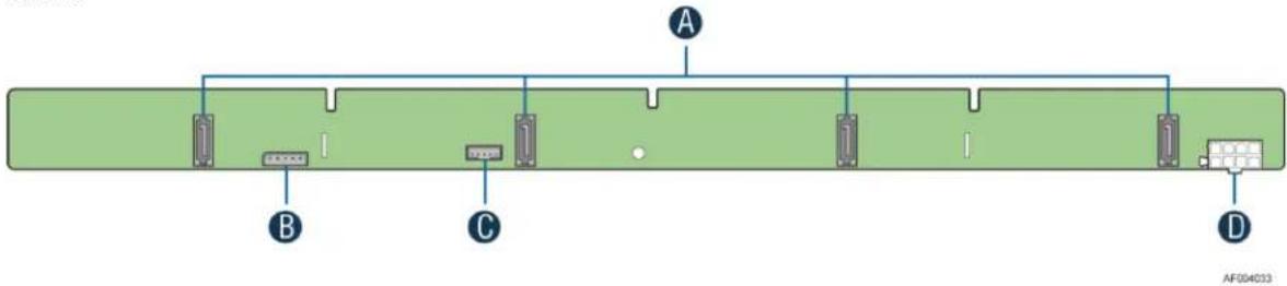
| Label | Description |
| A | 7-pin SATA/SAS I/O connectors |
| B | SMBus*-In cable connector – From Server board |
| C | SGPIO connector |
| D | Power connector |
Figure 32. The Back Side of 4 x 3.5" Hot Swap Backplane
A – 7-pin SATA I/O Connectors: The backplane has four 7-pin SATA/SAS I/O connectors, one for each hard drive. A single multi-connector cable is routed from the backplane to a four port mini-SAS connector on the server board or other optionally installed SATA/SAS host bus adapter.
B – SMBus* Cable Connectors: The backplane includes a 1x5 cable connector used as a management interface to the server board.
C – SGPIO Cable Connector: The SGPIO connector is a management interface used to control the hard drive fault LEDs on the backplane. The SGPIO signals are routed through a multi-connectors cable that is routed to a four port mini-SAS connector on the server board or other optionally installed SATA/SAS host bus adapter.
D – Power Harness Connector: The backplane includes a 2x2 connector supplying power to the backplane. Power is routed to the backplane through a power cable harness from the server board.
5.2.2 Cypress\* CY8C22545 Enclosure Management Controller
The backplanes support enclosure management using a Cypress* CY8C22545 Programmable System-on-Chip (PSoC*) device. The CY8C22545 drives the hard drive activity/fault LED, hard drive present signal, and controls hard drive power-up during the system power-on.
5.3 SATA DOM Support
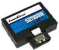
The system has support for a vertical low profile InnoDisk* SATA Disk-on-Module (DOM) device. The SATA DOM plugs directly into the 7-pin AHCI SATA port on the server board, which provides both power and I/O signals.
natural_image
Close-up of a black electronic device with a blue label and internal components (no readable text or symbols)Figure 33. InnoDisk* Low Profile SATA DOM
SATA DOM features include:
- Ultra Low Profile
■ High speed and capacity
■ Built-in VCC at pin 7
Note: Visit http://www.intel.com/p/en_US/support for a list of supported InnoDisk* SATA DOM parts.
6 Storage Controller Options Overview
The server platform supports many different embedded and add-in SATA/SAS controllers to provide a large number of possible storage configurations. This section provides an overview of the different options available.
6.1 Embedded SATA Controller Support
There are six 6Gb/s SATA ports on the motherboard. Intel® RSTe SW RAID through onboard SATA connectors provides SATA RAID 0/1/10/5. Intel® Embedded Server RAID Technology II through onboard SATA connectors provides SATA RAID 0/1/10 and optional RAID 5 support provided by the Intel® RAID Activation Key RKSATA4R5 on the connector of "SATA_KEY". S1200V3RPO and S1200V3RPM support one optional internal SAS module connector which supports Intel® SAS or ROC modules with the product code of RMS25CB080, RMS25JB080, RMS25CB040, and RMS25JB040.
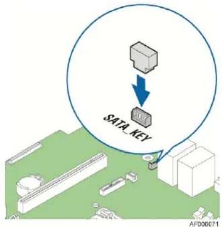
Figure 34. SATA_KEY Place
7 Front Control Panel and I/O Panel Overview
On the front panel of all system configurations is a Control Panel providing push button system controls and LED indicators for several system features, and an I/O Panel providing USB ports and a video connector. This section describes the features and functions of both front panel options.
7.1 I/O Panel Features
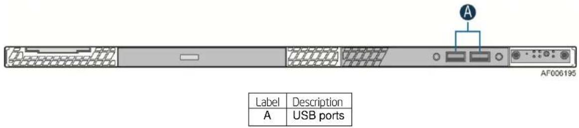
Figure 35. Front I/O Panel Features
A – USB Ports: The front I/O panel includes two USB ports. The USB ports are cabled to a 2x5 connector on the server board labeled "FP USB".
Note: On systems that support 8x2.5" hard drives, the I/O Panel can be replaced with a SATA optical drive.
7.2 Control Panel Features
The system includes a control panel that provides push button system controls and LED indicators for several system features. Depending on the hard drive configuration, the front control panel may come in either of two formats; however, both provide the same functionality. This section provides a description for each front control panel feature.
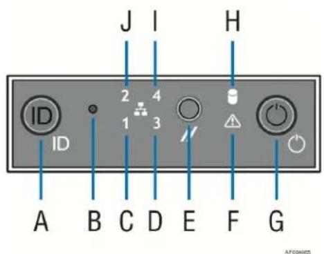
| Label | Description | Label | Description |
| A | System ID Button with Integrated LED | F | System Status LED |
| B | NMI Button (recessed, tool required for use) | G | Power/Sleep Button with Integrated LED |
| C | NIC-1 Activity LED | H | Hard Drive Activity LED |
| D | NIC-3 Activity LED | I | NIC-4 Activity LED |
| E | System Cold Reset Button | J | NIC-2 Activity LED |
Figure 36. Front Control Panel Features
A – System ID Button w/Integrated LED: Toggles the integrated ID LED and the Blue server board ID LED on and off. The System ID LED is used to identify the system for maintenance when installed in a rack of similar server systems. The System ID LED can also be toggled on and off remotely using the IPMI Chassis Identify command that causes the LED to blink for 15 seconds.
B – NMI Button: When the NMI button is pressed, it puts the server in a halt state and issues a non-maskable interrupt (NMI). This can be useful when performing diagnostics for a given issue where a memory download is necessary to help determine the cause of the problem. To prevent an inadvertent system halt, the actual NMI button is located behind the Front Control Panel faceplate where it is only accessible with the use of a small tipped tool like a pin or paper clip.
C, D, I, and J – Network Activity LEDs: The Front Control Panel includes an activity LED indicator for each on-board Network Interface Controller (NIC). When a network link is detected, the LED will turn on solid. The LED will blink once network activity occurs at a rate that is consistent with the amount of network activity that is occurring.
E – System Cold Reset Button: When pressed, this button will reboot and re-initialize the system.
F – System Status LED: The System Status LED is a bi-color (Green/Amber) indicator that shows the current health of the server system. The system provides two locations for this feature; one is located on the Front Control Panel, and the other is located on the back edge of the server board that is viewable from the back of the system. Both LEDs are tied together and show the same state. The System Status LED states are driven by the on-board platform management subsystem. The following table provides a description of each supported LED state.
Table 27. System Status LED State Definitions
| Color | State | Criticality | Description |
| Off | System is not operating | Not ready | 1. System is powered off (AC and/or DC).2. System is in EuP Lot6 Off Mode.3. System is in S5 Soft-Off State.4. System is in S4 Hibernate Sleep State. |
| Green | Solid on | Ok | Indicates that the System is running (in S0 State) and its status is 'Healthy'. The system is not exhibiting any errors. AC power is present and BMC has booted and manageability functionality is up and running. |
| Green | ~1 Hz blink | Degraded - system is operating in a degraded state although still functional, or system is operating in a redundant state but with an impending failure warning | System degraded:1. Redundancy loss, such as power-supply or fan. Applies only if the associated platform sub-system has redundancy capabilities.2. Fan warning or failure when the number of fully operational fans is more than minimum number needed to cool the system.3. Non-critical threshold crossed – Temperature (including HSBP temp), voltage, input power to power supply, output current for main power rail from power supply and Processor Thermal Control (Therm Ctrl) sensors.4. Power supply predictive failure occurred while redundant power supply configuration was present.5. Unable to use all of the installed memory (one or more DIMMs failed/disabled but functional memory remains available).6. Correctable Errors over a threshold and migrating to a spare DIMM (memory sparing). This indicates that the user no longer has spared DIMMs indicating a redundancy lost condition. Corresponding DIMM LED lit.7. Uncorrectable memory error has occurred in memory Mirroring Mode, causing Loss of Redundancy.8. Correctable memory error threshold has been reached for a failing DDR3 DIMM when the system is operating in fully redundant RAS Mirroring Mode.9. Battery failure.10. BMC executing in uBoot. (Indicated by Chassis ID blinking at Blinking at 3Hz). System in degraded state (no manageability). BMC uBoot is running but has not transferred control to BMC Linux*. Server will be in this state 6-8 seconds after BMC reset while it pulls the Linux* image into flash11. BMC booting Linux*. (Indicated by Chassis ID solid ON). System in degraded state (no manageability). Control has been passed from BMC uBoot to BMC Linux* itself. It will be in this state for ~10~-20 seconds.12. BMC Watchdog has reset the BMC.13. Power Unit sensor offset for configuration error is asserted.14. HDD HSC is off-line or degraded. |
| Amber | ~1 Hz blink | Non-critical - System is operating in a degraded state with an impending failure warning, although still functioning | Non-fatal alarm – system is likely to fail:1. Critical threshold crossed – Voltage, temperature (including HSBP temp), input power to power supply, output current for main power rail from power supply, and PROCHOT (Therm Ctrl) sensors.2. VRD Hot asserted.3. Minimum number of fans to cool the system not present or failed.4. Hard drive fault.5. Power Unit Redundancy sensor – Insufficient resources offset (indicates not enough power supplies present).6. In non-sparing and non-mirroring mode if the threshold of correctable errors is crossed within the window.7. Correctable memory error threshold has been reached for a failing DDR3 DIMM when the system is operating in a non-redundant mode. |
| Amber | Solid on | Critical, non-recoverable – System is halted | Fatal alarm – system has failed or shutdown:1. CPU CATERR signal asserted.2. MSID mismatch detected (CATERR also asserts for this case).3. CPU 1 is missing.4. CPU Thermal Trip.5. No power good – power fault.6. DIMM failure when there is only 1 DIMM present and hence no good memory present.7. Runtime memory uncorrectable error in non-redundant mode.8. DIMM Thermal Trip or equivalent.9. SSB Thermal Trip or equivalent.10. CPU ERR2 signal asserted.11. BMC\Video memory test failed. (Chassis ID shows blue/solid-on for this condition).12. Both uBoot BMC FW images are bad. (Chassis ID shows blue/solid-on for this condition).13. 240VA fault.14. Fatal Error in processor initialization:a. Processor family not identical.b. Processor model not identical.c. Processor core/thread counts not identical.d. Processor cache size not identical.e. Unable to synchronize processor frequency.f. Unable to synchronize QPI link frequency. |
G – Power/Sleep Button: Toggles the system power on and off. This button also functions as a sleep button if enabled by an ACPI compliant operating system. Pressing this button will send a signal to the Integrated BMC, which will either power on or power off the system. The integrated LED is a single color (Green) and can support different indicator states as defined in Table 28.
Table 28. Power/Sleep LED Functional States
| State | Power Mode | LED | Description |
| Power-off | Non-ACPI | Off | System power is off, and the BIOS has not initialized the chipset. |
| Power-on | Non-ACPI | On | System power is on. |
| S5 | ACPI | Off | Mechanical is off, and the operating system has not saved any context to the hard disk. |
| S4 | ACPI | Off | Mechanical is off. The operating system has saved context to the hard disk. |
| S3-S1 | ACPI | Slow blink1 | DC power is still on. The operating system has saved context and gone into a level of low-power state. |
| S0 | ACPI | Steady on | System and the operating system are up and running. |
H – Drive Activity LED: The drive activity LED on the front panel indicates drive activity from the on-board hard disk controllers. The server board also provides a header giving access to this LED for add-in controllers.
8 Intel ^® Local Control Panel
The Intel ^® Local Control Panel option (Intel ^® Product Order Code – AXXLCPANEL) utilizes a combination of control buttons and LCD display to provide system accessibility and monitoring.

natural_image
Front view of a rack-mounted server unit with indicator lights and ports (no visible text or labels)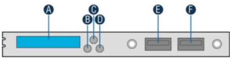
| Label | Description | Functionality |
| A | LCD Display | One line 18 character display |
| B | Left Control Button | Moves the cursor backward one step or one character |
| C | “Enter” Button | Selects the menu item highlighted by the cursor |
| D | Right Control Button | Moves the cursor forward one step or one character |
| E | USB 2.0 Port | |
| F | USB 2.0 Port |
Figure 37. Intel ^® Local Control Panel Option
The LCD (Local Control Display) is a one line character display that resides on the front panel of the chassis. It can display a maximum of 18 characters at a time. This device also contains three buttons (Left, Right, and Enter). The user can select the content that needs to be displayed on the LCD screen by operating these buttons.
8.1 LCD Functionality
The LCD device provides the following features:
- Displays a banner when the system is healthy. The default banner is the server name.
- Displays active error messages when the system is not healthy.
- Provides basic server management configuration.
- Provides the ability to see asset information without having to open the chassis.
The LCD display is menu driven. Based on the user's selection, respective menu items are displayed. As soon as AC Power is applied to the system, the LCD panel displays faults detected while the system is on standby power prior to the DC power on. If there are no faults, a banner is displayed. By default, the banner is a text string which displays the Server Name. The Server Name is the value specified as the product name in the product FRU information in the BMC FRU. Users can set any of the parameters under the banner configuration menu as a banner string.
When the system's status is degraded, the corresponding active event will be displayed in place of the banner. During an error, the background color will be light amber in color. The LCD panel displays the event with the highest severity that is most recent and is currently active (that is, in an asserted state). For the case that there are multiple active events with the same severity, the most recent event will be displayed. The LCD panel returns to a light blue background when there are no longer any degraded, non-fatal, or fatal events active. The LCD panel shall operate in lock-step with the system status LED. For example, if the system is operating normally and an event occurs that results in the system status LED to blink green, the LCD will display the degraded event that triggered the systems status LED to blink.
Banner
Figure 38. LCP Background Color during Normal Operation
Error
Figure 39. LCP Background Color during an Error
If the user presses any button after the system is powered on, the main menu will be displayed. The main menu contains Error, View, and Config items. Based on the user's selection, respective sub menu items will be displayed. At any point of time, if there is no user intervention for more than 10 minutes, a default banner (if there is no active error event in the system) or an error event will be displayed.
The following sections discuss the individual menu items. In the following sections, it is assumed that no active event exists during the LCD display. If any event (fatal or non-fatal) occurs that degrades the system's performance, the color of the LCD background turns into light amber. Even though all the contents (full text) are shown in the example screen shots in the following sections, by default, only the first 18 characters are displayed when a particular menu item is selected. The remaining text can be viewed by using right or left buttons.
8.2 Main Menu
If the user presses any button, when the Banner/Error screen is displayed, the following main menu will be displayed. Using left and right scroll buttons, the curser can be moved under any one of the following four menu items.
^ | Event | View | Config
Figure 40. LCP Main Menu
If the user selects menu item ^, the LCD displays the previous screen, that is, Banner/Error string. Selecting the menu item means moving the cursor under that item using left or right buttons and pressing enter button subsequently. In all the following sections (or for any screen shot), if the user presses Enter button, when the cursor is under the symbol ^, it takes to the previous screen. Selection of any of the menu items Event, View, or Config leads the display to their corresponding screen shots and the details of these screen shots are given in the following sections.
8.3 Event Menu
In the Event menu, the LCD displays the following items. It displays all active error events in human readable text in chronological order. Informational events are not displayed. There is no upper limit on the number of active events which can be displayed. The severity of the event will be indicated as any, Degraded, Non Fatal, or Fatal.
$$ \begin{array}{l} \text {^ | < - | -> | < Error - 1 >} \ \hline \end{array} $$
Figure 41. LCP Event Menu
The menu items <- and -> are used to traverse among the events. Selection of the menu item <- displays the previous event and the item -> displays the next event in human readable format. By default, the first event after the last power on will be displayed. If there are no events after the last power on, the fourth field is empty on the LCD screen.
By default, each error event scrolls automatically so that the entire error message can be read without pressing either the left or right scroll buttons. To stop auto scrolling, cursor has to be brought under the event message and the right button has to be pressed. Then the screen freezes. To start scrolling again right button has to be pressed when the cursor is under the event message. So, when the cursor is under event message, the right button decides whether to scroll or freeze the display of event message on the screen. When the cursor is under the event message, pressing enter button displays the failing FRU (if any) in an easily human readable format for that error event. Pressing Enter button alternatively switches the display between error message and the failing FRU (if any) information of that error message alternatively. If there is no FRU device associated with that error, Enter button has no effect when the cursor is under the error message. Left button moves the cursor under the previous token or menu item that is ->.
8.4 View Menu
The following screen is displayed when View is selected from the main menu.
$$ \begin{array}{c} \text {^ | SysFwVer | SysInfo | BMC IP} \ \text {Conf | RMM4 IP Config | Power | Last} \end{array} $$
Figure 42. LCP View Menu
Based on the user's selection, details of the specific item will be displayed. The following sub sections explain the above menu items in detail.
8.4.1 System FW Version (SysFwVer)
Selecting SysFwVer item in the View menu displays the current firmware versions of the system as shown below.
$$ \begin{array}{c} \text {^ | BIOS = xx.xx | BMC = xx.xx |} \ \text {ME = xx.xx | FRUSDR = xx.xx} \end{array} $$
Figure 43. System Firmware Versions Menu
This is a leaf node and there is no further traversal below this menu. User can only go to the previous screen by selecting the item ^. This applies to all the items of View menu.
8.4.2 System Information (SysInfo)
Selecting SysInfo item in the View menu displays the server's name, model, GUID, asset tag, and custom string. It is also a leaf node like above menu. The blanks in the following display will be replaced by their values.
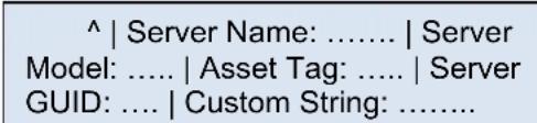
Figure 44. System Information Menu
Each of the above fields is explained below:
a. Server Name: Value specified in the product name in the product FRU information in the main board BMC FRU.
b. Server Model: Value specified in the product part number in the product FRU information in the main board BMC FRU.
c. Asset Tag: Value specified in the product asset tag in the product FRU information in the main board BMC FRU.
d. Server GUID: System UUID stored by BIOS.
e. Custom String: Custom string placed by the OEM\end user.
8.4.3 BMC IP Configuration
Selecting BMC IP Conf item in the View menu displays the RMM4 IP configuration details. These details show whether the IP is configured using DHCP or Static, IP Address, Subnet Mask, and Gateway.
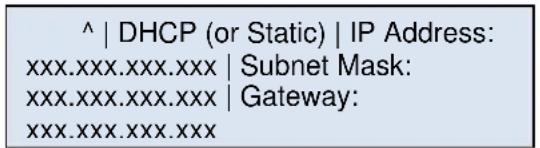
Figure 45. LCP – BMC IP Configuration
8.4.4 RMM4 IP Configuration
Selecting RMM4 IP Conf item in the View menu displays the BMC IP configuration details. These details show whether the IP is configured using DHCP or Static, IP Address, Subnet Mask, and Gateway.
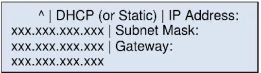
Figure 46. LCP – RMM4 IP Configuration
8.4.5 Power
Selecting Power item in the View menu displays the amount of AC power drawn by the system in Watts.
^ | xx W
Figure 47. LCP – Power Consumed by the System Currently
8.4.6 Last Post Code (Last PC)
Selecting Last PC item in the View menu displays the last BIOS POST code in hexadecimal.
^ | XX (Last BIOS POST Code in
Figure 48. LCP – Last BIOS Post Code
8.5 Config Menu
If the user selects Config item in the main menu, the following options will be displayed to configure.
^ | IP Version | BMC IP | RMM4 IP | Boot Device | Banner
Figure 49. LCP – Configure Menu Items
The following sub sections will explain individual items of the configuration menu.
8.5.1 IP Version
If the user selects IP Version in the Config menu, the following options will be displayed. Based the user's selection, firmware will set the IP Version as either IPv4 or IPv6.
^ | IPv4 | IPv6
Figure 50. LCP – IP Version Configuration Screen
8.5.2 BMC IP
If the user selects BMC IP item in the Config menu, the following options will be displayed.
| ^ | IP Source | IP Address | Subnet | Gateway |
Figure 51. LCP – BMC IP Configuration Menu
Selection of the IP Source in the above menu leads to the following screen. Based on the user's selection in the following menu, the firmware sets the BMC IP source as either DHCP or Static.
^ | DHCP | Static
Figure 52. LCP – BMC IP Source Configuration Menu
If the user selects DHCP or if the existing IP source is DHCP, the other menu items, that is, IP Address, Subnet, and Gateway are not configurable. If the user selects Static or if the existing setting is static for IP source, the user is allowed to change the other menu items and the screen shot looks as follows.
| ^ | IP: 000.000.000.000 | Set |
| ^ | Subnet: 000.000.000.000 | Set |
| ^ | Gateway: 000.000.000.000 | |
Figure 53. Screen Shot for Configuring IP Address, Subnet Mask, and Gateway
By default, the cursor will be under the symbol ^ and the IP address is displayed as 000.000.000.000. A right button will take the cursor to the first position (first 0) of the IP address. When the cursor is under the second menu item, the functionality of Left, Right, and Enter buttons is different from the previous screens. The second token consists of twelve 0 s' separated by period (.) character in IP address format. The behaviors of these buttons are as follows when the cursor is under this item:
- Left and Right buttons inside the second menu item traverse among the 0 positions within the same item.
- If the cursor is under last position inside the second menu item, a Right button will move the cursor to the next item, that is, Set.
- If the cursor is under first position inside the second menu item, a Left button moves the cursor to the previous item, that is, ^.
- First Enter button at any '0' position makes that position to be selected to increase or decrease the value at that position. The values allowed are between and including 0 and 9.
-
Any further Left or Right buttons will decrease or increase the value at that position.
-
Second Enter button at that position makes the cursor to be ready for moving left or right. Any further Left or Right button moves the cursor to previous or next position respectively.
-
The Enter button is used to select a position at the first time and to leave the position at the second time.
The following state transition diagram explains the above steps pictorially while setting an IP address using the LCD device. After entering an IP address, the user has to select Set item to set the entered IP address to the corresponding parameter (IP Address, Subnet Mask, or Gateway).
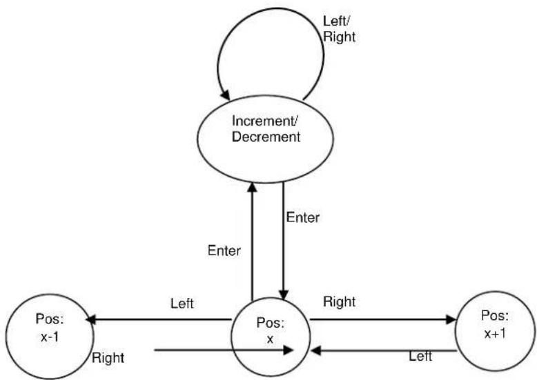
flowchart
graph TD
    A["Left/Right"] --> B["Increment/Decrement"]
    B --> C["Pos: x"]
    C --> D["Pos: x+1"]
    D --> E["Pos: x-1"]
    E --> F["Pos: x-1"]
    F --> G["Left"]
    G --> H["Pos: x"]
    H --> I["Right"]
    I --> J["Pos: x+1"]
    J --> K["Left"]
    K --> L["Pos: x-1"]
    L --> M["Right"]
    M --> N["Pos: x"]
    N --> O["Enter"]
    O --> P["Pos: x-1"]
    P --> Q["Left"]
    Q --> R["Pos: x-1"]
    R --> S["Right"]
    S --> T["Pos: x+1"]
    T --> U["Left"]
    U --> V["Pos: x-1"]
    V --> W["Right"]
    W --> X["Pos: x-1"]
    X --> Y["Left"]
    Y --> Z["Pos: x+1"]
    Z --> AA["Left"]
    AA --> AB["Pos: x-1"]
    AB --> AC["Right"]
    AC --> AD["Pos: x-1"]
Figure 54. State Transition Diagram for Setting IP Address
8.5.3 RMM4 IP
The screen shots and the description in the previous section (BMC IP) are also applicable for RMM4 IP configuration menu.
8.5.4 Boot Device
If the user selects Boot Device in the Config menu, the following options will be displayed. The selected item will be set as the next boot option and it will not be a permanent change.

Figure 55. Boot options Configuration Menu
8.5.5 Banner
When the user selects Banner in the Config menu, the following options will be displayed. The selected item will be set as banner and the same will be displayed from next banner screen onwards.
^ | Server Name | Server Model | Error | BMC IP | RMM4 IP | Power | Last PC | Custom String | Custom Logo
Figure 56. Banner Configuration Menu
Each of the menu items are explained below:
- Server Name: Displays the value specified in the product name in the product FRU information in the main board BMC FRU. The Server Name is the default banner.
- Server Model: Displays the value specified in the product part number in the product FRU information in the main board BMC FRU.
- Error: Displays the last active system event. The last active event may be degraded, non-critical, or critical only. It will not display an informational message. If the system is healthy, it displays System Health Ok.
- BMC IP: Displays the IPv4 or IPv6 address of BMC IP. If the BMC IP address is not configured, nothing is displayed.
- RMM4 IP: Displays the IPv4 or IPv6 address of RMM4 dedicated LAN IP. If the RMM4 IP is not set or not present, nothing is displayed.
- Power: Displays the current system power consumption in watts. The power consumed will be refreshed every minute.
- Last PC: Displays last BIOS post code.
- Custom string: Displays a customizable text string. The custom text string is modifiable through BIOS setup.
- Custom Logo: Displays a customizable bitmap logo. The OEM customized logo is programmed by the OEM and will be maintained during subsequent firmware updates.
9 PCIe Support and Riser Card Support
Intel ^® Server System R1304RPOSHBN, R1208RPOSHOR, and R1208RPMSHOR provide one PCI Express* x16 slot through one riser card. Intel ^® Server System R1304RPSSFBN provides one PCI Express* x8 slot through one riser card.
9.1 Architectural Overview of the Server Board Riser Slots
The following table lists the PCI Express* slot on the three motherboards and the mapping to the systems.
Table 29. PCI Express* Speed Matrix for Each Configuration
| Board Name | System Name | System PCIe slot through Riser card | ||
| S1200V3RPS | R1304RPSSFBN | PCI Express* Gen3 x8 on slot6 | ||
| S1200V3RPO | R1304RPOSHBN | Slot6 | IO Module | SAS module |
| S1200V3RPM | R1208RPOSHOR | PCI Express* Gen2 x16 or Gen3 x8 | Don't have add-in module | Don't have add-in module |
| R1208RPMSHOR | ||||
| PCI Express* Gen3 x8 or don't have add-in card | PCI Express* Gen2 x8 | Don't have add-in module | ||
| Don't have add-in module | PCI Express* Gen2 x8 | |||
| PCI Express* Gen2 x4 | PCI Express* Gen2 x4 | |||
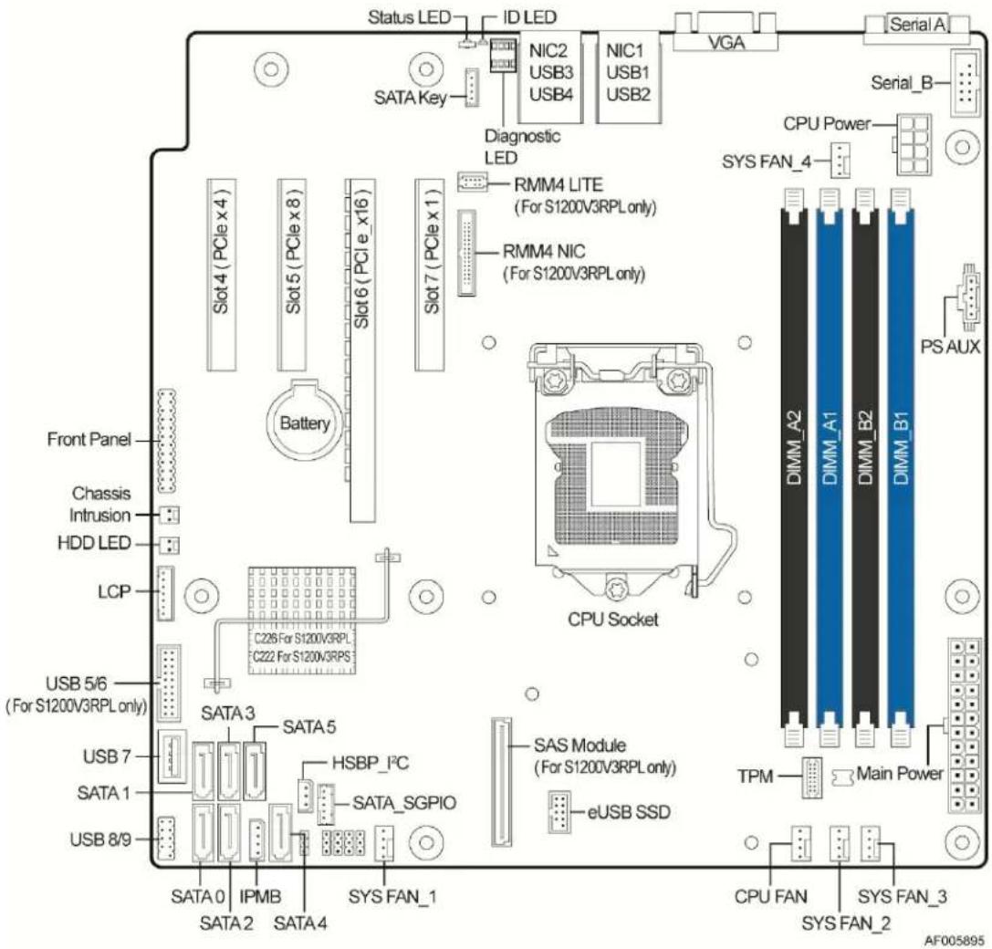
Figure 57. PCIe SLOT Drawing
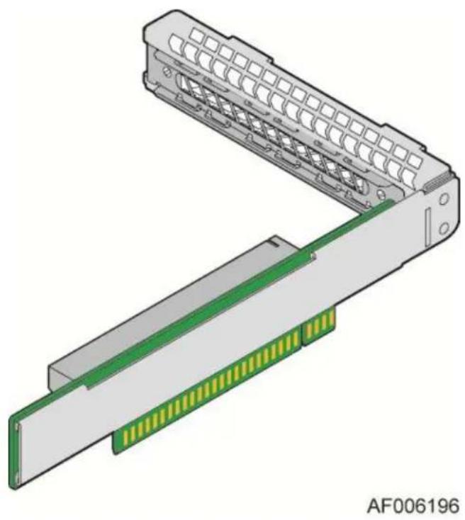
natural_image
3D diagram of a mechanical connector assembly with green and yellow traces, no text or symbols presentFigure 58. 1U Riser Card Drawing
You can get the installation steps from the Intel ^® Server System R1000RP Family Service Guide to assemble the add-in video card.
Appendix A: Integration and Usage Tips
Before attempting to integrate and configure your system, you should reference this section, which provides a list of useful information.
- After the system is integrated with processors, memory, and peripheral devices, the FRUSDR utility must be run to load the proper Sensor Data Record data to the integrated Server Management subsystem. Failure to run this utility may prevent Server Management from accurately monitoring system health and may affect system performance. The FRUSDR utility for this server system can either be run from the Intel® Deployment CDROM that came with your system or can be downloaded from the Intel® website referenced at the bottom of this page.
- To ensure the highest system reliability, make sure the latest system software is loaded on the server before deploying the system onto a live networking environment. This includes system BIOS, FRUSDR, BMC firmware, and hot-swap controller firmware. The system software can be updated using the Intel® Deployment DVD that came with your system or can be downloaded from the Intel® website referenced at the bottom of this page.
■ System fans are not hot-swappable. - Only supported memory validated by Intel should be used in this server system. A list of supported memory can be found in the Intel® Server Board S1200V3RP Tested Memory List which can be downloaded from the Intel® website referenced at the bottom of this page.
- This system supports the Intel ^ Xeon ^ processor E3-1200 V3 series. You cannot use Intel ^ Xeon ^ processors not referenced on the supported processor list in this server system.
- You must use the CPU/memory air duct to maintain system thermals.
- To maintain system thermals, you must populate all hard drive bays with either a hard drive or drive blank.
- You must remove AC power from the system prior to opening the chassis for service.
You can download the latest system documentation, drivers, and system software from the Intel® Support website at http://www.intel.com/p/en_US/support/highlights/server/R1000RP.
Appendix B: POST Code LED Decoder
As an aid to assist in troubleshooting a system hang that occurs during a system's Power-On Self Test (POST) process, the server board includes a bank of eight POST Code Diagnostic LEDs on the back edge of the server board.
During the system boot process, Memory Reference Code (MRC) and System BIOS execute a number of memory initialization and platform configuration processes, each of which is assigned a specific hex POST code number. As each routine is started, the given POST code number is displayed to the POST Code Diagnostic LEDs on the back edge of the server board.
During a POST system hang, the displayed post code can be used to identify the last POST routine that was run prior to the error occurring, helping to isolate the possible cause of the hang condition.
Each POST code is represented by eight LEDs; four Green and four Amber. The POST codes are divided into two nibbles, an upper nibble and a lower nibble. The upper nibble bits are represented by Amber Diagnostic LEDs #4, #5, #6, and #7. The lower nibble bits are represented by Green Diagnostics LEDs #0, #1, #2, and #3. If the bit is set in the upper and lower nibbles, the corresponding LED is lit. If the bit is clear, the corresponding LED is off.
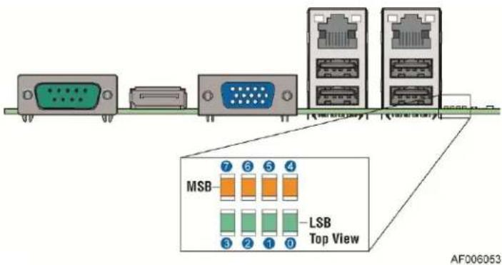
Figure 59. Diagnostic LED Location
In the following example, the BIOS sends a value of ACh to the diagnostic LED decoder. The LEDs are decoded as follows.
Note: Diag LEDs are best read and decoded when viewing the LEDs from the back of the system.
Table 30. POST Progress Code LED Example
| LEDs | Upper Nibble AMBER LEDs | Lower Nibble GREEN LEDs | ||||||
| MSB | LSB | |||||||
| LED #7 | LED #6 | LED #5 | LED #4 | LED #3 | LED #2 | LED #1 | LED #0 | |
| 8h | 4h | 2h | 1h | 8h | 4h | 2h | 1h | |
| Status | ON | OFF | ON | OFF | ON | ON | OFF | OFF |
| Results | 1 | 0 | 1 | 0 | 1 | 1 | 0 | 0 |
| Ah | Ch | |||||||
Upper nibble bits = 1010b = Ah; Lower nibble bits = 1100b = Ch; the two are concatenated as ACh.
The following table provides a list of all POST progress codes.
Table 31. Diagnostic LED POST Progress Codes
| Checkpoint | Diagnostic LED Decoder | Description | |||||||
| 1 = LED On, 0 = LED Off | |||||||||
| Upper Nibble | Lower Nibble | ||||||||
| MSB | LSB | ||||||||
| 8h | 4h | 2h | 1h | 8h | 4h | 2h | 1h | ||
| LED # | #7 | #6 | #5 | #4 | #3 | #2 | #1 | #0 | |
| SEC Phase | |||||||||
| 01h | 0 | 0 | 0 | 0 | 0 | 0 | 0 | 1 | First POST code after CPU reset |
| 02h | 0 | 0 | 0 | 0 | 0 | 0 | 1 | 0 | Microcode load begin |
| 03h | 0 | 0 | 0 | 0 | 0 | 0 | 1 | 1 | CRAM initialization begin |
| 04h | 0 | 0 | 0 | 0 | 0 | 1 | 0 | 0 | Pei Cache When Disabled |
| 05h | 0 | 0 | 0 | 0 | 0 | 1 | 0 | 1 | SEC Core At Power On Begin. |
| 06h | 0 | 0 | 0 | 0 | 0 | 1 | 1 | 0 | Early CPU initialization during Sec Phase. |
| 07h | 0 | 0 | 0 | 0 | 0 | 1 | 1 | 1 | Early SB initialization during Sec Phase. |
| 08h | 0 | 0 | 0 | 0 | 1 | 0 | 0 | 0 | Early NB initialization during Sec Phase. |
| 09h | 0 | 0 | 0 | 0 | 1 | 0 | 0 | 1 | End Of Sec Phase. |
| 0Eh | 0 | 0 | 0 | 0 | 1 | 1 | 1 | 0 | Microcode Not Found. |
| 0Fh | 0 | 0 | 0 | 0 | 1 | 1 | 1 | 1 | Microcode Not Loaded. |
| PEI Phase | |||||||||
| 10h | 0 | 0 | 0 | 1 | 0 | 0 | 0 | 0 | PEI Core |
| 11h | 0 | 0 | 0 | 1 | 0 | 0 | 0 | 1 | CPU PEIM |
| 15h | 0 | 0 | 0 | 1 | 0 | 1 | 0 | 1 | NB PEIM |
| 19h | 0 | 0 | 0 | 1 | 1 | 0 | 0 | 1 | SB PEIM |
| MRC Process Codes - MRC Progress Code Sequence is executed - See Table 63 | |||||||||
| PEI Phase continued... | |||||||||
| 31h | 0 | 0 | 1 | 1 | 0 | 0 | 0 | 1 | Memory Installed |
| 32h | 0 | 0 | 1 | 1 | 0 | 0 | 1 | 0 | CPU PEIM (Cpu Init) |
| 33h | 0 | 0 | 1 | 1 | 0 | 0 | 1 | 1 | CPU PEIM (Cache Init) |
| 34h | 0 | 0 | 1 | 1 | 0 | 1 | 0 | 0 | CPU PEIM (BSP Select) |
| 35h | 0 | 0 | 1 | 1 | 0 | 1 | 0 | 1 | CPU PEIM (AP Init) |
| 36h | 0 | 0 | 1 | 1 | 0 | 1 | 1 | 0 | CPU PEIM (CPU SMM Init) |
| 4Fh | 0 | 1 | 0 | 0 | 1 | 1 | 1 | 1 | Dxe IPL started |
| DXE Phase | |||||||||
| 60h | 0 | 1 | 1 | 0 | 0 | 0 | 0 | 0 | DXE Core started |
| 61h | 0 | 1 | 1 | 0 | 0 | 0 | 0 | 1 | DXE NVRAM Init |
| 62h | 0 | 1 | 1 | 0 | 0 | 0 | 1 | 0 | SB RUN Init |
| 63h | 0 | 1 | 1 | 0 | 0 | 0 | 1 | 1 | Dxe CPU Init |
| 68h | 0 | 1 | 1 | 0 | 1 | 0 | 0 | 0 | DXE PCI Host Bridge Init |
| 69h | 0 | 1 | 1 | 0 | 1 | 0 | 0 | 1 | DXE NB Init |
| 6Ah | 0 | 1 | 1 | 0 | 1 | 0 | 1 | 0 | DXE NB SMM Init |
| 70h | 0 | 1 | 1 | 1 | 0 | 0 | 0 | 0 | DXE SB Init |
| 71h | 0 | 1 | 1 | 1 | 0 | 0 | 0 | 1 | DXE SB SMM Init |
| 72h | 0 | 1 | 1 | 1 | 0 | 0 | 1 | 0 | DXE SB devices Init |
| 78h | 0 | 1 | 1 | 1 | 1 | 0 | 0 | 0 | DXE ACPI Init |
| 79h | 0 | 1 | 1 | 1 | 1 | 0 | 0 | 1 | DXE CSM Init |
| 90h | 1 | 0 | 0 | 1 | 0 | 0 | 0 | 0 | DXE BDS Started |
| 91h | 1 | 0 | 0 | 1 | 0 | 0 | 0 | 1 | DXE BDS connect drivers |
| 92h | 1 | 0 | 0 | 1 | 0 | 0 | 1 | 0 | DXE PCI Bus begin |
| 93h | 1 | 0 | 0 | 1 | 0 | 0 | 1 | 1 | DXE PCI Bus HPC Init |
| 94h | 1 | 0 | 0 | 1 | 0 | 1 | 0 | 0 | DXE PCI Bus enumeration |
| 95h | 1 | 0 | 0 | 1 | 0 | 1 | 0 | 1 | DXE PCI Bus resource requested |
| 96h | 1 | 0 | 0 | 1 | 0 | 1 | 1 | 0 | DXE PCI Bus assign resource |
| 97h | 1 | 0 | 0 | 1 | 0 | 1 | 1 | 1 | DXE CON_OUT connect |
| 98h | 1 | 0 | 0 | 1 | 1 | 0 | 0 | 0 | DXE CON_IN connect |
| 99h | 1 | 0 | 0 | 1 | 1 | 0 | 0 | 1 | DXE SIO Init |
| 9Ah | 1 | 0 | 0 | 1 | 1 | 0 | 1 | 0 | DXE USB start |
| 9Bh | 1 | 0 | 0 | 1 | 1 | 0 | 1 | 1 | DXE USB reset |
| 9Ch | 1 | 0 | 0 | 1 | 1 | 1 | 0 | 0 | DXE USB detect |
| 9Dh | 1 | 0 | 0 | 1 | 1 | 1 | 0 | 1 | DXE USB enable |
| A1h | 1 | 0 | 1 | 0 | 0 | 0 | 0 | 1 | DXE IDE begin |
| A2h | 1 | 0 | 1 | 0 | 0 | 0 | 1 | 0 | DXE IDE reset |
| A3h | 1 | 0 | 1 | 0 | 0 | 0 | 1 | 1 | DXE IDE detect |
| A4h | 1 | 0 | 1 | 0 | 0 | 1 | 0 | 0 | DXE IDE enable |
| A5h | 1 | 0 | 1 | 0 | 0 | 1 | 0 | 1 | DXE SCSI begin |
| A6h | 1 | 0 | 1 | 0 | 0 | 1 | 1 | 0 | DXE SCSI reset |
| A7h | 1 | 0 | 1 | 0 | 0 | 1 | 1 | 1 | DXE SCSI detect |
| A8h | 1 | 0 | 1 | 0 | 1 | 0 | 0 | 0 | DXE SCSI enable |
| A9h | 1 | 0 | 1 | 0 | 1 | 0 | 0 | 1 | DXE verifying SETUP password |
| ABh | 1 | 0 | 1 | 0 | 1 | 0 | 1 | 1 | DXE SETUP start |
| ACh | 1 | 0 | 1 | 0 | 1 | 1 | 0 | 0 | DXE SETUP input wait |
| ADh | 1 | 0 | 1 | 0 | 1 | 1 | 0 | 1 | DXE Ready to Boot |
| AEh | 1 | 0 | 1 | 0 | 1 | 1 | 1 | 0 | DXE Legacy Boot |
| AFh | 1 | 0 | 1 | 0 | 1 | 1 | 1 | 1 | DXE Exit Boot Services |
| B0h | 1 | 0 | 1 | 1 | 0 | 0 | 0 | 0 | RT Set Virtual Address Map Begin |
| B1h | 1 | 0 | 1 | 1 | 0 | 0 | 0 | 1 | RT Set Virtual Address Map End |
| B2h | 1 | 0 | 1 | 1 | 0 | 0 | 1 | 0 | DXE Legacy Option ROM init |
| B3h | 1 | 0 | 1 | 1 | 0 | 0 | 1 | 1 | DXE Reset system |
| B4h | 1 | 0 | 1 | 1 | 0 | 1 | 0 | 0 | DXE USB Hot plug |
| B5h | 1 | 0 | 1 | 1 | 0 | 1 | 0 | 1 | DXE PCI BUS Hot plug |
| B6h | 1 | 0 | 1 | 1 | 0 | 1 | 1 | 0 | DXE NVRAM cleanup |
| B7h | 1 | 0 | 1 | 1 | 0 | 1 | 1 | 1 | DXE Configuration Reset |
| 00h | 0 | 0 | 0 | 0 | 0 | 0 | 0 | 0 | INT19 |
| S3 Resume | |||||||||
| E0h | 1 | 1 | 0 | 1 | 0 | 0 | 0 | 0 | S3 Resume PEIM (S3 started) |
| E1h | 1 | 1 | 0 | 1 | 0 | 0 | 0 | 1 | S3 Resume PEIM (S3 boot script) |
| E2h | 1 | 1 | 0 | 1 | 0 | 0 | 1 | 0 | S3 Resume PEIM (S3 Video Repost) |
| E3h | 1 | 1 | 0 | 1 | 0 | 0 | 1 | 1 | S3 Resume PEIM (S3 OS wake) |
| BIOS Recovery | |||||||||
| F0h | 1 | 1 | 1 | 1 | 0 | 0 | 0 | 0 | PEIM which detected forced Recovery condition |
| F1h | 1 | 1 | 1 | 1 | 0 | 0 | 0 | 1 | PEIM which detected User Recovery condition |
| F2h | 1 | 1 | 1 | 1 | 0 | 0 | 1 | 0 | Recovery PEIM (Recovery started) |
| F3h | 1 | 1 | 1 | 1 | 0 | 0 | 1 | 1 | Recovery PEIM (Capsule found) |
| F4h | 1 | 1 | 1 | 1 | 0 | 1 | 0 | 0 | Recovery PEIM (Capsule loaded) |
POST Memory Initialization MRC Diagnostic Codes
There are two types of POST Diagnostic Codes displayed by the MRC during memory initialization; Progress Codes and Fatal Error Codes.
The MRC Progress Codes are displays to the Diagnostic LEDs that show the execution point in the MRC operational path at each step.
Table 32. MRC Progress Codes
| Checkpoint | Diagnostic LED Decoder | Description | |||||||
| 1 = LED On, 0 = LED Off | |||||||||
| Upper Nibble | Lower Nibble | ||||||||
| MSB | LSB | ||||||||
| 8h | 4h | 2h | 1h | 8h | 4h | 2h | 1h | ||
| LED | #7 | #6 | #5 | #4 | #3 | #2 | #1 | #0 | |
| MRC Progress Codes | |||||||||
| B0h | 1 | 0 | 1 | 1 | 0 | 0 | 0 | 0 | Detect DIMM population |
| B1h | 1 | 0 | 1 | 1 | 0 | 0 | 0 | 1 | Set DDR3 frequency |
| B2h | 1 | 0 | 1 | 1 | 0 | 0 | 1 | 0 | Gather remaining SPD data |
| B3h | 1 | 0 | 1 | 1 | 0 | 0 | 1 | 1 | Program registers on the memory controller level |
| B4h | 1 | 0 | 1 | 1 | 0 | 1 | 0 | 0 | Evaluate RAS modes and save rank information |
| B5h | 1 | 0 | 1 | 1 | 0 | 1 | 0 | 1 | Program registers on the channel level |
| B6h | 1 | 0 | 1 | 1 | 0 | 1 | 1 | 0 | Perform the JEDEC defined initialization sequence |
| B7h | 1 | 0 | 1 | 1 | 0 | 1 | 1 | 1 | Train DDR3 ranks |
| B8h | 1 | 0 | 1 | 1 | 1 | 0 | 0 | 0 | Initialize CLTT/OLTT |
| B9h | 1 | 0 | 1 | 1 | 1 | 0 | 0 | 1 | Hardware memory test and init |
| BAh | 1 | 0 | 1 | 1 | 1 | 0 | 1 | 0 | Execute software memory init |
| BBh | 1 | 0 | 1 | 1 | 1 | 0 | 1 | 1 | Program memory map and interleaving |
| BCh | 1 | 0 | 1 | 1 | 1 | 1 | 0 | 0 | Program RAS configuration |
| BFh | 1 | 0 | 1 | 1 | 1 | 1 | 1 | 1 | MRC is done |
Memory initialization at the beginning of POST includes multiple functions, including discovery, channel training, validation that the DIMM population is acceptable and functional, initialization of the IMC and other hardware settings, and initialization of applicable RAS configurations.
When a major memory initialization error occurs and prevents the system from booting with data integrity, a beep code is generated, the MRC will display a fatal error code on the diagnostic LEDs, and a system halt command is executed. Fatal MRC error halts do NOT change the state of the System Status LED, and they do NOT get logged as SEL events. The following table lists all MRC fatal errors that are displayed to the Diagnostic LEDs.
Table 33. MRC Fatal Error Codes
| Checkpoint | Diagnostic LED Decoder | Description | |||||||
| 1 = LED On, 0 = LED Off | |||||||||
| Upper Nibble | Lower Nibble | ||||||||
| MSB | LSB | ||||||||
| 8h | 4h | 2h | 1h | 8h | 4h | 2h | 1h | ||
| LED | #7 | #6 | #5 | #4 | #3 | #2 | #1 | #0 | |
| MRC Fatal Error Codes | |||||||||
| E8h | 1 | 1 | 1 | 0 | 1 | 0 | 0 | 0 | No usable memory error01h = No memory was detected from the SPD read, or invalid config that causes no operable memory.02h = Memory DIMMs on all channels of all sockets are disabled due to hardware memtest error.3h = No memory installed. All channels are disabled. |
| E9h | 1 | 1 | 1 | 0 | 1 | 0 | 0 | 1 | Memory is locked by Intel ^ Trusted Execution Technology and is inaccessible |
| EAh | 1 | 1 | 1 | 0 | 1 | 0 | 1 | 0 | DDR3 channel training error01h = Error on read DQ/DQS (Data/Data Strobe) init02h = Error on Receive Enable3h = Error on Write Leveling04h = Error on write DQ/DQS (Data/Data Strobe |
| EBh | 1 | 1 | 1 | 0 | 1 | 0 | 1 | 1 | Memory test failure01h = Software memtest failure.02h = Hardware memtest failed.03h = Hardware Memtest failure in Lockstep Channel mode requiring a channel to be disabled. This is a fatal error which requires a reset and calling MRC with a different RAS mode to retry. |
| EDh | 1 | 1 | 1 | 0 | 1 | 1 | 0 | 1 | DIMM configuration population error01h = Different DIMM types (UDIMM, RDIMM, LRDIMM) are detected installed in the system.02h = Violation of DIMM population rules.03h = The third DIMM slot cannot be populated when QR DIMMs are installed.04h = UDIMMs are not supported in the third DIMM slot.05h = Unsupported DIMM Voltage. |
| EFh | 1 | 1 | 1 | 0 | 1 | 1 | 1 | 1 | Indicates a CLTT table structure error |
Appendix C: POST Code Errors
Most error conditions encountered during POST are reported using POST Error Codes. These codes represent specific failures, warnings, or are informational. POST Error Codes may be displayed in the Error Manager display screen, and are always logged to the System Event Log (SEL). Logged events are available to System Management applications, including Remote and Out of Band (OOB) management.
There are exception cases in early initialization where system resources are not adequately initialized for handling POST Error Code reporting. These cases are primarily Fatal Error conditions resulting from initialization of processors and memory, and they are handed by a Diagnostic LED display with a system halt.
The following table lists the supported POST Error Codes. Each error code is assigned an error type which determines the action the BIOS will take when the error is encountered. Error types include Minor, Major, and Fatal. The BIOS action for each is defined as follows:
- Minor: The error message is displayed on the screen or on the Error Manager screen, and an error is logged to the SEL. The system continues booting in a degraded state. The user may want to replace the erroneous unit. The POST Error Pause option setting in the BIOS setup does not have any effect on this error.
- Major: The error message is displayed on the Error Manager screen, and an error is logged to the SEL. The POST Error Pause option setting in the BIOS setup determines whether the system pauses to the Error Manager for this type of error so the user can take immediate corrective action or the system continues booting.
Note that for 0048 "Password check failed", the system halts, and then after the next reset/reboot will display the error code on the Error Manager screen.
- Fatal: The system halts during post at a blank screen with the text “Unrecoverable fatal error found. System will not boot until the error is resolved” and “Press
When the operator presses the F2 key on the keyboard, the error message is displayed on the Error Manager screen, and an error is logged to the SEL with the error code. The system cannot boot unless the error is resolved. The user needs to replace the faulty part and restart the system.
Note: The POST error codes in the following table are common to all current generation Intel ^® server platforms. Features present on a given server board/system will determine which of the listed error codes are supported.
Table 34. POST Error Message and Handling
| Error Code | Error Message | Response |
| 0012 | System RTC date/time not set | Major |
| 0048 | Password check failed | Major |
| 0140 | PCI component encountered a PERR error | Major |
| 0141 | PCI resource conflict | Major |
| 0146 | PCI out of resources error | Major |
| 0191 | Processor core/thread count mismatch detected | Fatal |
| 0192 | Processor cache size mismatch detected | Fatal |
| 0194 | Processor family mismatch detected | Fatal |
| 0195 | Processor Intel® QPI link frequencies unable to synchronize | Fatal |
| 0196 | Processor model mismatch detected | Fatal |
| 0197 | Processor frequencies unable to synchronize | Fatal |
| 5220 | BIOS Settings reset to default settings | Major |
| 5221 | Passwords cleared by jumper | Major |
| 5224 | Password clear jumper is Set | Major |
| 8130 | Processor 01 disabled | Major |
| 8131 | Processor 02 disabled | Major |
| 8132 | Processor 03 disabled | Major |
| 8133 | Processor 04 disabled | Major |
| 8160 | Processor 01 unable to apply microcode update | Major |
| 8161 | Processor 02 unable to apply microcode update | Major |
| 8162 | Processor 03 unable to apply microcode update | Major |
| 8163 | Processor 04 unable to apply microcode update | Major |
| 8170 | Processor 01 failed Self Test (BIST) | Major |
| 8171 | Processor 02 failed Self Test (BIST) | Major |
| 8172 | Processor 03 failed Self Test (BIST) | Major |
| 8173 | Processor 04 failed Self Test (BIST) | Major |
| 8180 | Processor 01 microcode update not found | Minor |
| 8181 | Processor 02 microcode update not found | Minor |
| 8182 | Processor 03 microcode update not found | Minor |
| 8183 | Processor 04 microcode update not found | Minor |
| 8190 | Watchdog timer failed on last boot | Major |
| 8198 | OS boot watchdog timer failure | Major |
| 8300 | Baseboard management controller failed self-test | Major |
| 8305 | Hot Swap Controller failure | Major |
| 83A0 | Management Engine (ME) failed Self Test | Major |
| 83A1 | Management Engine (ME) Failed to respond. | Major |
| 84F2 | Baseboard management controller failed to respond | Major |
| 84F3 | Baseboard management controller in update mode | Major |
| 84F4 | Sensor data record empty | Major |
| 84FF | System event log full | Minor |
| 8500 | Memory component could not be configured in the selected RAS mode | Major |
| 8501 | DIMM Population Error | Major |
| 8520 | DIMM_A1 failed test/initialization | Major |
| 8521 | DIMM_A2 failed test/initialization | Major |
| 8522 | DIMM_A3 failed test/initialization | Major |
| 8523 | DIMM_B1 failed test/initialization | Major |
| 8524 | DIMM_B2 failed test/initialization | Major |
| 8525 | DIMM_B3 failed test/initialization | Major |
| 8526 | DIMM_C1 failed test/initialization | Major |
| 8527 | DIMM_C2 failed test/initialization | Major |
| 8528 | DIMM_C3 failed test/initialization | Major |
| 8529 | DIMM_D1 failed test/initialization | Major |
| 852A | DIMM_D2 failed test/initialization | Major |
| 852B | DIMM_D3 failed test/initialization | Major |
| 852C | DIMM_E1 failed test/initialization | Major |
| 852D | DIMM_E2 failed test/initialization | Major |
| 852E | DIMM_E3 failed test/initialization | Major |
| 852F | DIMM_F1 failed test/initialization | Major |
| 8530 | DIMM_F2 failed test/initialization | Major |
| 8531 | DIMM_F3 failed test/initialization | Major |
| 8532 | DIMM_G1 failed test/initialization | Major |
| 8533 | DIMM_G2 failed test/initialization | Major |
| 8534 | DIMM_G3 failed test/initialization | Major |
| 8535 | DIMM_H1 failed test/initialization | Major |
| 8536 | DIMM_H2 failed test/initialization | Major |
| 8537 | DIMM_H3 failed test/initialization | Major |
| 8538 | DIMM_I1 failed test/initialization | Major |
| 8539 | DIMM_I2 failed test/initialization | Major |
| 853A | DIMM_I3 failed test/initialization | Major |
| 853B | DIMM_J1 failed test/initialization | Major |
| 853C | DIMM_J2 failed test/initialization | Major |
| 853D | DIMM_J3 failed test/initialization | Major |
| 853E | DIMM_K1 failed test/initialization | Major |
| 853F(Go to 85C0) | DIMM_K2 failed test/initialization | Major |
| 8540 | DIMM_A1 disabled | Major |
| 8541 | DIMM_A2 disabled | Major |
| 8542 | DIMM_A3 disabled | Major |
| 8543 | DIMM_B1 disabled | Major |
| 8544 | DIMM_B2 disabled | Major |
| 8545 | DIMM_B3 disabled | Major |
| 8546 | DIMM_C1 disabled | Major |
| 8547 | DIMM_C2 disabled | Major |
| 8548 | DIMM_C3 disabled | Major |
| 8549 | DIMM_D1 disabled | Major |
| 854A | DIMM_D2 disabled | Major |
| 854B | DIMM_D3 disabled | Major |
| 854C | DIMM_E1 disabled | Major |
| 854D | DIMM_E2 disabled | Major |
| 854E | DIMM_E3 disabled | Major |
| 854F | DIMM_F1 disabled | Major |
| 8550 | DIMM_F2 disabled | Major |
| 8551 | DIMM_F3 disabled | Major |
| 8552 | DIMM_G1 disabled | Major |
| 8553 | DIMM_G2 disabled | Major |
| 8554 | DIMM_G3 disabled | Major |
| 8555 | DIMM_H1 disabled | Major |
| 8556 | DIMM_H2 disabled | Major |
| 8557 | DIMM_H3 disabled | Major |
| 8558 | DIMM_I1 disabled | Major |
| 8559 | DIMM_I2 disabled | Major |
| 855A | DIMM_I3 disabled | Major |
| 855B | DIMM_J1 disabled | Major |
| 855C | DIMM_J2 disabled | Major |
| 855D | DIMM_J3 disabled | Major |
| 855E | DIMM_K1 disabled | Major |
| 855F(Go to 85D0) | DIMM_K2 disabled | Major |
| 8560 | DIMM_A1 encountered a Serial Presence Detection (SPD) failure | Major |
| 8561 | DIMM_A2 encountered a Serial Presence Detection (SPD) failure | Major |
| 8562 | DIMM_A3 encountered a Serial Presence Detection (SPD) failure | Major |
| 8563 | DIMM_B1 encountered a Serial Presence Detection (SPD) failure | Major |
| 8564 | DIMM_B2 encountered a Serial Presence Detection (SPD) failure | Major |
| 8565 | DIMM_B3 encountered a Serial Presence Detection (SPD) failure | Major |
| 8566 | DIMM_C1 encountered a Serial Presence Detection (SPD) failure | Major |
| 8567 | DIMM_C2 encountered a Serial Presence Detection (SPD) failure | Major |
| 8568 | DIMM_C3 encountered a Serial Presence Detection (SPD) failure | Major |
| 8569 | DIMM_D1 encountered a Serial Presence Detection (SPD) failure | Major |
| 856A | DIMM_D2 encountered a Serial Presence Detection (SPD) failure | Major |
| 856B | DIMM_D3 encountered a Serial Presence Detection (SPD) failure | Major |
| 856C | DIMM_E1 encountered a Serial Presence Detection (SPD) failure | Major |
| 856D | DIMM_E2 encountered a Serial Presence Detection (SPD) failure | Major |
| 856E | DIMM_E3 encountered a Serial Presence Detection (SPD) failure | Major |
| 856F | DIMM_F1 encountered a Serial Presence Detection (SPD) failure | Major |
| 8570 | DIMM_F2 encountered a Serial Presence Detection (SPD) failure | Major |
| 8571 | DIMM_F3 encountered a Serial Presence Detection (SPD) failure | Major |
| 8572 | DIMM_G1 encountered a Serial Presence Detection (SPD) failure | Major |
| 8573 | DIMM_G2 encountered a Serial Presence Detection (SPD) failure | Major |
| 8574 | DIMM_G3 encountered a Serial Presence Detection (SPD) failure | Major |
| 8575 | DIMM_H1 encountered a Serial Presence Detection (SPD) failure | Major |
| 8576 | DIMM_H2 encountered a Serial Presence Detection (SPD) failure | Major |
| 8577 | DIMM_H3 encountered a Serial Presence Detection (SPD) failure | Major |
| 8578 | DIMM_I1 encountered a Serial Presence Detection (SPD) failure | Major |
| 8579 | DIMM_I2 encountered a Serial Presence Detection (SPD) failure | Major |
| 857A | DIMM_I3 encountered a Serial Presence Detection (SPD) failure | Major |
| 857B | DIMM_J1 encountered a Serial Presence Detection (SPD) failure | Major |
| 857C | DIMM_J2 encountered a Serial Presence Detection (SPD) failure | Major |
| 857D | DIMM_J3 encountered a Serial Presence Detection (SPD) failure | Major |
| 857E | DIMM_K1 encountered a Serial Presence Detection (SPD) failure | Major |
| 857F(Go to 85E0) | DIMM_K2 encountered a Serial Presence Detection (SPD) failure | Major |
| 85C0 | DIMM_K3 failed test/initialization | Major |
| 85C1 | DIMM_L1 failed test/initialization | Major |
| 85C2 | DIMM_L2 failed test/initialization | Major |
| 85C3 | DIMM_L3 failed test/initialization | Major |
| 85C4 | DIMM_M1 failed test/initialization | Major |
| 85C5 | DIMM_M2 failed test/initialization | Major |
| 85C6 | DIMM_M3 failed test/initialization | Major |
| 85C7 | DIMM_N1 failed test/initialization | Major |
| 85C8 | DIMM_N2 failed test/initialization | Major |
| 85C9 | DIMM_N3 failed test/initialization | Major |
| 85CA | DIMM_O1 failed test/initialization | Major |
| 85CB | DIMM_O2 failed test/initialization | Major |
| 85CC | DIMM_O3 failed test/initialization | Major |
| 85CD | DIMM_P1 failed test/initialization | Major |
| 85CE | DIMM_P2 failed test/initialization | Major |
| 85CF | DIMM_P3 failed test/initialization | Major |
| 85D0 | DIMM_K3 disabled | Major |
| 85D1 | DIMM_L1 disabled | Major |
| 85D2 | DIMM_L2 disabled | Major |
| 85D3 | DIMM_L3 disabled | Major |
| 85D4 | DIMM_M1 disabled | Major |
| 85D5 | DIMM_M2 disabled | Major |
| 85D6 | DIMM_M3 disabled | Major |
| 85D7 | DIMM_N1 disabled | Major |
| 85D8 | DIMM_N2 disabled | Major |
| 85D9 | DIMM_N3 disabled | Major |
| 85DA | DIMM_O1 disabled | Major |
| 85DB | DIMM_O2 disabled | Major |
| 85DC | DIMM_O3 disabled | Major |
| 85DD | DIMM_P1 disabled | Major |
| 85DE | DIMM_P2 disabled | Major |
| 85DF | DIMM_P3 disabled | Major |
| 85E0 | DIMM_K3 encountered a Serial Presence Detection (SPD) failure | Major |
| 85E1 | DIMM_L1 encountered a Serial Presence Detection (SPD) failure | Major |
| 85E2 | DIMM_L2 encountered a Serial Presence Detection (SPD) failure | Major |
| 85E3 | DIMM_L3 encountered a Serial Presence Detection (SPD) failure | Major |
| 85E4 | DIMM_M1 encountered a Serial Presence Detection (SPD) failure | Major |
| 85E5 | DIMM_M2 encountered a Serial Presence Detection (SPD) failure | Major |
| 85E6 | DIMM_M3 encountered a Serial Presence Detection (SPD) failure | Major |
| 85E7 | DIMM_N1 encountered a Serial Presence Detection (SPD) failure | Major |
| 85E8 | DIMM_N2 encountered a Serial Presence Detection (SPD) failure | Major |
| 85E9 | DIMM_N3 encountered a Serial Presence Detection (SPD) failure | Major |
| 85EA | DIMM_O1 encountered a Serial Presence Detection (SPD) failure | Major |
| 85EB | DIMM_O2 encountered a Serial Presence Detection (SPD) failure | Major |
| 85EC | DIMM_O3 encountered a Serial Presence Detection (SPD) failure | Major |
| 85ED | DIMM_P1 encountered a Serial Presence Detection (SPD) failure | Major |
| 85EE | DIMM_P2 encountered a Serial Presence Detection (SPD) failure | Major |
| 85EF | DIMM_P3 encountered a Serial Presence Detection (SPD) failure | Major |
| 8604 | POST Reclaim of non-critical NVRAM variables | Minor |
| 8605 | BIOS Settings are corrupted | Major |
| 8606 | NVRAM variable space was corrupted and has been reinitialized | Major |
| 92A3 | Serial port component was not detected | Major |
| 92A9 | Serial port component encountered a resource conflict error | Major |
| A000 | TPM device not detected. | Minor |
| A001 | TPM device missing or not responding. | Minor |
| A002 | TPM device failure. | Minor |
| A003 | TPM device failed self test. | Minor |
| A100 | BIOS ACM Error | Major |
| A421 | PCI component encountered a SERR error | Fatal |
| A5A0 | PCI Express* component encountered a PERR error | Minor |
| A5A1 | PCI Express* component encountered an SERR error | Fatal |
| A6A0 | DXE Boot Service driver: Not enough memory available to shadow a Legacy Option ROM | Minor |
POST Error Beep Codes
The following table lists POST error beep codes. Prior to system video initialization, the BIOS uses these beep codes to inform users on error conditions. The beep code is followed by a user-visible code on POST Progress LEDs.
Table 35. POST Error Beep Codes
| Beeps | Error Message | POST Progress Code | Description |
| 1 | USB device action | NA | Short beep sounded whenever a USB device is discovered in POST, or inserted or removed during runtime |
| 1 long | Intel® TXT security violation | 0xAE, 0xAF | System halted because Intel® Trusted Execution Technology detected a potential violation of system security. |
| 3 | Memory error | See Tables 28 and 29 | System halted because a fatal error related to the memory was detected. |
| 2 | BIOS Recovery started | NA | Recovery boot has been initiated |
| 4 | BIOS Recovery failure | NA | BIOS recovery has failed. This typically happens so quickly after recovery us initiated that it sounds like a 2-4 beep code. |
Integrated BMC Beep Codes
The Integrated BMC may generate beep codes upon detection of failure conditions. Beep codes are sounded each time the problem is discovered, such as on each power-up attempt, but are not sounded continuously. Codes that are common across all Intel ^® server boards and systems that use same generation chipset are listed in the following table. Each digit in the code is represented by a sequence of beeps whose count is equal to the digit.
Table 36. Integrated BMC Beep Codes
| Code | Reason for Beep | Associated Sensors |
| 1-5-2-1 | No CPUs installed or first CPU socket is empty. | CPU1 socket is empty, or sockets are populated incorrectlyCPU1 must be populated before CPU2. |
| 1-5-2-4 | MSID Mismatch | MSID mismatch occurs if a processor is installed into a system board that has incompatible power capabilities. |
| 1-5-4-2 | Power fault | DC power unexpectedly lost (power good dropout) – Power unit sensors report power unit failure offset |
| 1-5-4-4 | Power control fault (power good assertion timeout). | Power good assertion timeout – Power unit sensors report soft power control failure offset |
| 1-5-1-2 | VR Watchdog Timer sensor assertion | VR controller DC power on sequence was not completed in time. |
| 1-5-1-4 | Power Supply Status | The system does not power on or unexpectedly powers off and a Power Supply Unit (PSU) is present that is an incompatible model with one or more other PSUs in the system. |
Glossary
| Term | Definition |
| ACPI | Advanced Configuration and Power Interface |
| AP | Application Processor |
| APIC | Advanced Programmable Interrupt Control |
| ASIC | Application Specific Integrated Circuit |
| ASMI | Advanced Server Management Interface |
| BIOS | Basic Input/Output System |
| BIST | Built-In Self Test |
| BMC | Baseboard Management Controller |
| Bridge | Circuitry connecting one computer bus to another, allowing an agent on one to access the other |
| BSP | Bootstrap Processor |
| Byte | 8-bit quantity |
| CBC | Chassis Bridge Controller (A microcontroller connected to one or more other CBCs, together they bridge the IPMB buses of multiple chassis.) |
| CEK | Common Enabling Kit |
| CHAP | Challenge Handshake Authentication Protocol |
| CMOS | In terms of this specification, this describes the PC-AT compatible region of battery-backed 128 bytes of memory, which normally resides on the server board |
| DPC | Direct Platform Control |
| EEPROM | Electrically Erasable Programmable Read-Only Memory |
| EHCI | Enhanced Host Controller Interface |
| EMP | Emergency Management Port |
| EPS | External Product Specification |
| ESB2-E | Enterprise South Bridge 2 |
| FBD | Fully Buffered DIMM |
| FMB | Flexible Mother Board |
| FRB | Fault Resilient Booting |
| FRU | Field Replaceable Unit |
| FSB | Front Side Bus |
| GB | 1024MB |
| GPIO | General Purpose I/O |
| GTL | Gunning Transceiver Logic |
| HSC | Hot-Swap Controller |
| Hz | Hertz (1 cycle/second) |
| I2C | Inter-Integrated Circuit Bus |
| IA | Intel® Architecture |
| IBF | Input Buffer |
| ICH | I/O Controller Hub |
| ICMB | Intelligent Chassis Management Bus |
| IERR | Internal Error |
| IFB | I/O and Firmware Bridge |
| INTR | Interrupt |
| IP | Internet Protocol |
| IPMB | Intelligent Platform Management Bus |
| IPMI | Intelligent Platform Management Interface |
| IR | Infrared |
| ITP | In-Target Probe |
| KB | 1024 bytes |
| KCS | Keyboard Controller Style |
| LAN | Local Area Network |
| LCD | Liquid Crystal Display |
| LED | Light Emitting Diode |
| LPC | Low Pin Count |
| LUN | Logical Unit Number |
| MAC | Media Access Control |
| MB | 1024KB |
| MCH | Memory Controller Hub |
| MD2 | Message Digest 2 – Hashing Algorithm |
| MD5 | Message Digest 5 – Hashing Algorithm – Higher Security |
| ms | milliseconds |
| MTTR | Memory Type Range Register |
| Mux | Multiplexor |
| NIC | Network Interface Controller |
| NMI | Nonmaskable Interrupt |
| OBF | Output Buffer |
| OEM | Original Equipment Manufacturer |
| Ohm | Unit of electrical resistance |
| PDB | Power Distribution Board |
| PEF | Platform Event Filtering |
| PEP | Platform Event Paging |
| PIA | Platform Information Area (This feature configures the firmware for the platform hardware.) |
| PLD | Programmable Logic Device |
| PMI | Platform Management Interrupt |
| POST | Power-On Self Test |
| PSMI | Power Supply Management Interface |
| PWM | Pulse-Width Modulation |
| RAM | Random Access Memory |
| RASUM | Reliability, Availability, Serviceability, Usability, and Manageability |
| RISC | Reduced Instruction Set Computing |
| RMM3 | Remote Management Module – 3^rd generation |
| RMM3 NIC | Remote Management Module – 3^rd generation dedicated management NIC |
| ROM | Read Only Memory |
| RTC | Real-Time Clock (Component of ICH peripheral chip on the server board.) |
| SDR | Sensor Data Record |
| SECC | Single Edge Connector Cartridge |
| SEEPROM | Serial Electrically Erasable Programmable Read-Only Memory |
| SEL | System Event Log |
| SIO | Server Input/Output |
| SMI | Server Management Interrupt (SMI is the highest priority nonmaskable interrupt.) |
| SMM | Server Management Mode |
| SMS | Server Management Software |
| SNMP | Simple Network Management Protocol |
| SSI | Server System Infrastructure |
| TBD | To Be Determined |
| TIM | Thermal Interface Material |
| UART | Universal Asynchronous Receiver/Transmitter |
| UDP | User Datagram Protocol |
| UHCI | Universal Host Controller Interface |
| UTC | Universal time coordinate |
| VID | Voltage Identification |
| VRD | Voltage Regulator Down |
| Word | 16-bit quantity |
| ZIF | Zero Insertion Force |
Reference Documents
Refer to the following documents for additional information:
Intel ^® Server Board S1200V3RP Technical Product Specification
■ ACPI 3.0: http://www.acpi.info/spec.htm
■ IPMI 2.0
■ Data Center Management Interface Specification v1.0, May 1, 2008: www.intel.com/go/dcmi
■ PCI Bus Power Management Interface Specification 1.1: http://www.pcisig.com/
■ PCI Express* Base Specification Rev 2.0, Dec 06: http://www.pcisig.com/
- PCI Express* Card Electromechanical Specification, Rev 2.0: http://www.pcisig.com/
■ PMBus*: http://pmbus.org
■ SATA 2.6: http://www.sata-io.org/
■ SMBIOS 2.4
■ SSI-EEB 3.0: http://www.ssiforum.org/
USB 1.1: http://www.usb.org
USB 2.0: http://www.usb.org
- Windows* Logo/SDG 3.0
Intel ^® Dynamic Power Technology Node Manager 1.5 External Interface Specification using IPMI, 2007. Intel Corporation.
- Node Power and Thermal Management Architecture Specification v1.5, rev.0.79. 2007, Intel Corporation.
Intel ^® Server System Integrated Baseboard Management Controller Core External Product Specification, 2007 Intel Corporation.
Intel ^® Thurley Server Platform Services IPMI Commands Specification, 2007. Intel Corporation.
Intel ^® Server Safety and Regulatory, 2012. Intel Corporation. (Intel ^® Order Code: G23122)
- Intelligent Platform Management Bus Communications Protocol Specification, Version 1.0, 1998. Intel Corporation, Hewlett-Packard* Company, NEC* Corporation, Dell* Computer Corporation.
■ Platform Environmental Control Interface (PECI) Specification, Version 2.0. Intel Corporation.
- Platform Management FRU Information Storage Definition, Version 1.0, Revision 1.2, 2002. Intel Corporation, Hewlett-Packard* Company, NEC* Corporation, Dell* Computer Corporation: http://developer.intel.com/design/servers/ipmi/spec.htm.
- Intel® Server System R1000RP Family
- Disclaimers
- Table of Contents
- Introduction .... 1
- Product Overview....2
- Power Subsystem....13
- Thermal Management....28
- System Storage and Peripheral Options....35
- Storage Controller Options Overview 40
- Front Control Panel and I/O Panel Overview 41
- Intel ® Local Control Panel....46
- PCIe Support and Riser Card Support....54
- Appendix A: Integration and Usage Tips ....57
- Appendix B: POST Code LED Decoder ....58
- Appendix C: POST Code Errors....63
- Glossary 69
- Reference Documents....72
- List of Figures
- List of Tables
- Introduction
- Chapter Outline
- Server Board Use Disclaimer
- Product Overview
- System Views
- System Dimensions
- System Level Environmental Limits
- System Features and Options Overview
- Hot Swap Hard Drive Bay and Front Panel Options
- Back Panel Features
- Front Control Panel Options
- Server Board Overview
- Rear Component View
- Available Front Bezel Support (Optional)
- Available Rack and Cabinet Mounting Kit Options
- Power Subsystem
- 350W Fixed Power Supply
- Mechanical Overview
- Power Supply Module Efficiency
- Power Cord Specification Requirements
- AC Input Requirement
- Power Factor
- AC Input Voltage Specification
- Notes:
- AC Line Isolation Requirements
- AC Line Dropout/Holdup
- AC Line Fuse
- AC Inrush
- AC Line Leakage Current
- AC Line Transient Specification
- Susceptibility Requirements
- Electrostatic Discharge Susceptibility
- AIR DISCHARGE ±8kV CONTACT DISCHARGE ±4kV
- Fast Transient/Burst
- Radiated Immunity
- Surge Immunity
- Power Recovery
- Voltage Interruptions
- DC Output Specification
- Output Power/Currents
- Standby Output
- Protection Circuits
- Over Current Protection (OCP)
- Over Voltage Protection (OVP)
- Over Temperature Protection (OTP)
- 450W mini-ERPS Redundant Power Supply
- Mechanical Overview
- Power Supply Module Card Edge Connector
- Power Supply Module Efficiency
- Power Cord Specification Requirements
- AC Input Requirement
- Power Factor
- AC Input Voltage Specification
- AC Line Isolation Requirements
- AC Line Dropout/Holdup
- AC Line Fuse
- AC Inrush
- AC Line Leakage Current
- AC Line Transient Specification
- Susceptibility Requirements
- Electrostatic Discharge Susceptibility
- Fast Transient/Burst
- Radiated Immunity
- Surge Immunity
- Power Recovery
- Voltage Interruptions
- DC Output Specification
- Output Power/Currents
- Standby Output
- Protection Circuits
- Current Limit (OCP)
- Over Voltage Protection (OVP)
- Over Temperature Protection (OTP)
- Thermal Management
- Thermal Operation and Configuration Requirements
- Thermal Management Overview
- Set Throttling Mode
- Altitude
- Set Fan Profile
- Fan PWM Offset
- Quiet Fan Idle Mode
- Thermal Sensor Input for Fan Speed Control
- Intel ® Server System R1000RP Family TPS Thermal Management
- System Fans
- FRUSDR Utility
- System Storage and Peripheral Options
- 2.5" Hard Disk Drive Support
- 2.5" Drive Hot-Swap Backplane Overview
- Cypress\* CY8C22545 Enclosure Management Controller
- 3.5" Hard Disk Drive Support
- 3.5" Drive Hot-Swap Backplane Overview
- Cypress\* CY8C22545 Enclosure Management Controller
- SATA DOM Support
- Storage Controller Options Overview
- Embedded SATA Controller Support
- Front Control Panel and I/O Panel Overview
- I/O Panel Features
- Control Panel Features
- Intel ® Local Control Panel
- LCD Functionality
- Main Menu
- Event Menu
- View Menu
- System FW Version (SysFwVer)
- System Information (SysInfo)
- BMC IP Configuration
- RMM4 IP Configuration
- Power
- Last Post Code (Last PC)
- Config Menu
- IP Version
- BMC IP
- RMM4 IP
- Boot Device
- Banner
- Figure 56. Banner Configuration Menu
- PCIe Support and Riser Card Support
- Architectural Overview of the Server Board Riser Slots
- Appendix A: Integration and Usage Tips
- Appendix B: POST Code LED Decoder
- POST Memory Initialization MRC Diagnostic Codes
- Appendix C: POST Code Errors
- POST Error Beep Codes
- Integrated BMC Beep Codes
- Reference Documents
Brand : INTEL
Model : R1208RPMSHOR
Category : Server