
IC-7010PoE - Security Camera Edimax - Free user manual and instructions
Find the device manual for free IC-7010PoE Edimax in PDF.


| Product Type | Security IP Camera (Indoor) |
| Model | IC-7010PoE |
| Image Sensor | 1.3 Megapixel 1/4" Color CMOS |
| Max Resolution | 1280 x 1024 (SXGA) |
| Video Compression | H.264, MPEG4, MJPEG |
| Frame Rate | Up to 30 fps at QVGA, 20 fps at VGA, 10-15 fps at SXGA/XGA |
| Lens | Fixed, with manual focus ring |
| Pan/Tilt Range | Pan: ±170°, Tilt: ±90° (approximate) |
| Night Vision | 9 IR LEDs, auto switch (range approx. 5m) |
| Network Interface | 10/100Mbps Ethernet with PoE (IEEE 802.3af) |
| Audio | Built-in microphone, external speaker output |
| Storage | SD/SDHC card slot (up to 32GB, not included) |
| Power Supply | 12V DC 1A or PoE (IEEE 802.3af) |
| Power Consumption | Approx. 5W |
| Operating Temperature | 0°C to 40°C |
| Dimensions (W x H x D) | Approx. 122 x 122 x 150 mm |
| Weight | Approx. 350 g |
| Mounting | Ceiling/Wall mount (bracket included), tripod mount |
| Web Interface | Yes (IE with ActiveX, also Chrome/Firefox with plug-in) |
| Surveillance Software | Included, supports up to 16 cameras |
| Motion Detection | Yes, with configurable sensitivity and email/FTP alerts |
| DDNS Support | Yes (dyndns.org) |
| UPnP | Yes |
| RTSP Streaming | Yes (port 554) |
| Certification | FCC, CE Class B |
Frequently Asked Questions - IC-7010PoE Edimax
User questions about IC-7010PoE Edimax
0 question about this device. Answer the ones you know or ask your own.
Ask a new question about this device
Download the instructions for your Security Camera in PDF format for free! Find your manual IC-7010PoE - Edimax and take your electronic device back in hand. On this page are published all the documents necessary for the use of your device. IC-7010PoE by Edimax.
USER MANUAL IC-7010PoE Edimax
Fast Ethernet / 300Mbps Wireless 802.11n / PoE Triple Mode Pan/Tilt IP Camera with Night Vision
IC-7010PT / IC-7010PTn / IC-7010PoE User Manual
Version 1.0 / June, 2010
natural_image
Exterior view of a modern office building (no signage)
natural_image
Exterior view of a silver remote control device (no text or symbols visible)
natural_image
Exterior view of a silver TP587 dual-camera security camera with visible ports and control buttons (no text or symbols)ErP Announcement
Product: Internet Camera (IP Camera)
Purpose: 24 hour surveillance and transfer of footage for safety and health reasons as intended use.
Detailed description:
- Health purposes: Users can pass through the Internet (from anywhere) to control the product (IP Camera). It's intended to watch and listen to people who need to be cared for at home and automatically sends e-mails and phone alerts to warn observers and ask for their attention. The product also provides a record function to retain all images and voice information for the sake of reference.
- Safety purposes: Users can initiate a “motion detect” function to record and send e-mails to notify them when doors or windows are opened – potentially by unwarranted persons.
- General purposes: Record/monitor environment footage and sound and store them onto a hard disk as a record.
As we cannot predict when events of this nature may occur, we need for the product to remain active and alert at all times. If the product had to go into “standby/off” mode, it would impact the effectiveness of recording and warning functions resulting in users not getting the information they need.
Based on the ErP official journal of European Union
Directives 2009/125/CE of the European parliament and of the council of 21 October 2009 Article 15 sector 5 part (a) and (b) as below:
“Implementing measures shall have no significant negative impact on the functionality of the product, from the perspective of the user.”
"Health, safety and environment shall not be adversely affected."
We announce that the product need not comply with the (EC) No 1275 Standby and on/off mode function of Implementing Measurement.
We will keep up to the newest Implementing Measurements in the future and make the necessary changes if it's related to this product.
ΣDIMAX NETWORKING PEOPLE TOGETHER
Copyright© by Edimax Technology Co, LTD. all rights reserved. No part of this publication may be reproduced, transmitted, transcribed, stored in a retrieval system, or translated into any language or computer language, in any form or by any means, electronic, mechanical, magnetic, optical, chemical, manual or otherwise, without the prior written permission of this company.
This company makes no representations or warranties, either expressed or implied, with respect to the contents hereof and specifically disclaims any warranties, merchantability or fitness for any particular purpose. Any software described in this manual is sold or licensed "as is". Should the programs prove defective following their purchase, the buyer (and not this company, its distributor, or its dealer) assumes the entire cost of all necessary servicing, repair, and any incidental or consequential damages resulting from any defect in the software. Further, this company reserves the right to revise this publication and to make changes from time to time in the contents hereof without obligation to notify any person of such revision or changes.
The product you have purchased and the setup screen may appear slightly different from those shown in this QIG. For more detailed information about this product, please refer to the User Manual on the CD-ROM. The software and specifications are subject to change without notice. Please visit our web site www.edimax.com for the update. All rights reserved including all brand and product names mentioned in this manual are trademarks and/or registered trademarks of their respective holders.
Notice according to GNU/GPL-Version 2
This product includes software that is subject to the GNU/GPL-Version 2. You find the text of the license on the product cd/dvd. The program is free software and distributed without any warranty of the author. We offer, valid for at least three years, to give you, for a charge no more than the costs of physically performing source distribution, a complete machine-readable copy of the corresponding source code.
Please contact Edimax at: Edimax Technology co., Ltd, NO. 3, Wu-Chuan 3rd RD Wu-Ku-Industrial Park, Taipei Hsien, Taiwan. R.O.C., TEL : +886-2-77396888, FAX : +886-2-77396887, sales@edimax.com.tw
Table of Contents
Chapter I: Familiar with your Internet IP Camera 6
1.1 Package Contents ......6
1.2 Basic Introduction ...... 7
1.3 Product Highlights....8
1.4 Familiar with Key Components ......9
IC-7010PT: 11
IC-7010PTn: 12
IC-7010PoE:....13
1.5 Camera Installation....17
1.6 Locate the IP Address of this IP Camera 20
1.7 Using Camera Admin Software to Locate Camera 24
Chapter II: Using Web Management Interface 36
2.1 Camera Settings....36
2.2 Video....40
2.2.1 MJPEG 41
2.2.2 MPEG4 42
2.2.3 H.264 43
2.2.4 OSD 44
2.2.5 Night Vision....45
2.3 Pan and Tilt....46
2.3.1 Preset Points 46
2.3.2 Guard Tour....48
2.4 Network Settings....51
2.4.1 LAN....52
2.4.2 WLAN 55
2.4.3 Dynamic DNS 58
2.4.4 UPnP 59
2.4.5 LoginFree 61
2.4.6 RTSP 62
2.5 Motion Detection....63
2.5.1 Motion Detection....64
2.5.2 Motion Region 66
2.6 System Info....73
2.6.1 Camera Information....74
2.6.2 Date / Time Setting 75
2.6.3 Schedule....77
2.6.4 Utilities....79
2.6.5 Status....81
2.6.6 System Log....82
2.7 Account....83
2.7.1 Status....86
2.7.2 Space Alarm 87
2.7.3 File Management....89
Chapter III: Using Surveillance Software....90
3-1 Installing IP Camera Surveillance Software 90
3-2 Using IP camera surveillance software....94
3-3 Configure IP camera surveillance software 97
3-3-1 Configure cameras....97
3-3-2 General Settings 106
3-4 Change Display Layout 112
3-5 Full-screen mode....115
3-6 Scan 116
3-7 Zoom-in / Zoom-out....117
3-8 PTZ....118
3-9 Snapshot 119
3-10 Recording .... 120
3-11 Video Playback....121
Chapter IV: How to View IP Camera over the Internet with iPhone......122
Chapter V: Appendix 129
5.1 Specification....129
5.2 How to apply for a free DNS account in the http://www.dyndns.org 130
5.3 Troubleshooting....133
Chapter I: Familiar with your Internet IP Camera
1.1 Package Contents
Thank you for purchasing this IP camera! Before you start to use this IP camera, please check the package contents. If anything is missing, please contact the dealer of purchase and return the package to claim for missing contents.
| Item Name | Quantity | |
| 1 | IP Camera | 1 |
| 2 | Antenna(IC-7010PTn only) | 2 |
| 3 | Power Adapter | 1 |
| 4 | Ethernet Cable | 1 |
| 5 | CD ROM (Including Manual/Utility/Multi-Language QIG) | 1 |
| 6 | Accessory kit | 1 |
| 7 | Quick Installation Guide | 1 |
| 8 | Mounting Kit | 1 |
1.2 Basic Introduction
Thank you for purchasing this IP camera! This IP camera is an ideal product for all kinds of video surveillance purposes, like home/office safety, kid/pet monitoring, and remote video acquire etc. Edimax IC-7010 series is tailor made to stream live video over your network. You can view the IP camera's video from anywhere on your local computers or via the Internet. Besides, Edimax IC-7010 series features high quality and high frame rate video streaming through advanced video compression. In order to achieve the highest video quality, simply select H.264, MPEG4 or M-JPEG depending on your network settings.
Some people may concern that there will be some places which will not be covered by camera, but this problem is completely solved by this IP camera. With built-in pan-tilt function, you can point the camera to the position where you wish to look at with user interface. You can even define a preset path, and the camera will cruise along the path you defined.
If the environment is too dark, it's also not a problem. This camera equips 9 IR-LEDs and will illuminate automatically when the environment is too dark, and the image captured by this camera will still be clear.
You can discover more useful functions in next section!
1.3 Product Highlights
No pre-loaded software required - all you need is a browser like Internet Explorer 6 (and above, with plugin installed).
With supplied video surveillance software, you can connect up to 16 video cameras and view images captured by every camera at the same time.
Supports 3 video resolutions: MJPG and H.264 SXGA(1280 x 1024), VGA (640 x 480), and QVGA (320 x 240); MPEG4 XGA (1024 x 768), VGA (640 x 480), and QVGA (320 x 240).
Anti-flicker function (eliminates flash caused by fluorescent lights, 50 / 60Hz selectable).
Video control functions, like brightness and zoom-in / zoom-out.
Audio function, suitable for applications like video conference or environment monitor.
Pan-tilt control.
9 automatically-controlled IR LEDs.
Wired and wireless network (IC-7010PTn only, 802.11b / 802.11g / 802.11n) support
Wireless data encryption (WEP / WPA)
Supports DHCP and PPPoE protocol, you can also assign a fixed IP address to the camera also.
Supports Dynamic DNS (used to allocate the IP camera's Internet address, when the ISP you're using does not assign you with a fixed Internet address).
Supports UPnP, Windows XP (and above) will discover this IP camera in network neighbor automatically.
Send captured picture and video by Email or FTP when motion is detected.
Configurable motion detection sensitivity (6 levels from most sensitive to least sensitive).
Built-in real-time clock, date and time information will be recorded with every captured picture / video clip (also supports auto time synchronization via network time protocol).
Upgradeable firmware - enjoy new functions without buying a new camera!
Supports up to 16 users, and you can set different password to different user.
Usage and event logging.
1.4 Familiar with Key Components
Front View
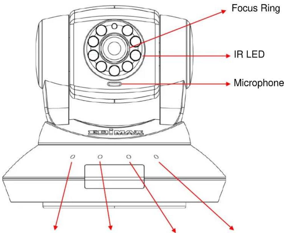
Wired & Wireless:
Power LED
Audio LED
LAN LED
WLAN LED
POE model:
Power LED
Audio LED
ACT LED
LAN LED
| Item | Description |
Power | When the camera is powered on and ready for access, this LED will light up. |
| Audio((●)) | Indicates Audio status |
 | When the IP Camera is linked to a wired network, this LED will light up. The LED will flash while video is transmitted or received through a wired network. |
ACT (IC-7010) (IC-7010) | The LED will flash while data is transmitted. |
| PoE only) | |
| Wireless(IC-7010 PT & IC-7010 PTn only) | When the IP Camera is linked to a wireless network, this LED will light up. The LED will flash while video is transmitted or received through a wireless network. |
| Focus Ring | You can change the aim and focus of the camera by adjusting the camera head's aim and adjusting the focus ring. Simply point it in your direction of choice and rotate the focus ring to your preference. |
| IR LEDs | Lights up when environment is too dark |
| Microph one | Collects audio |
Back View
IC-7010PT:
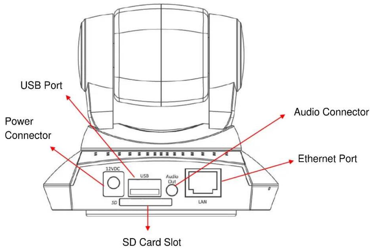
IC-7010PTn:
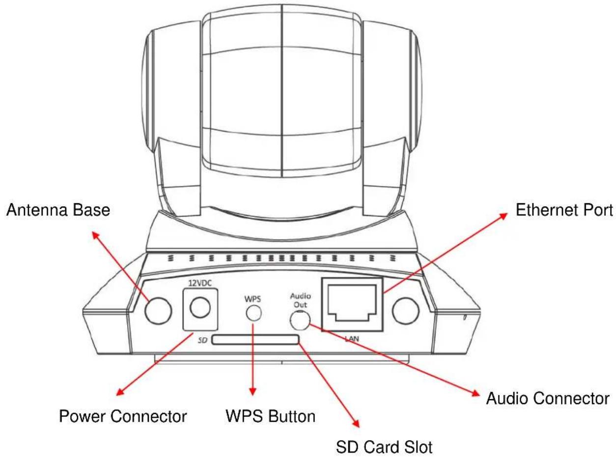
IC-7010PoE:
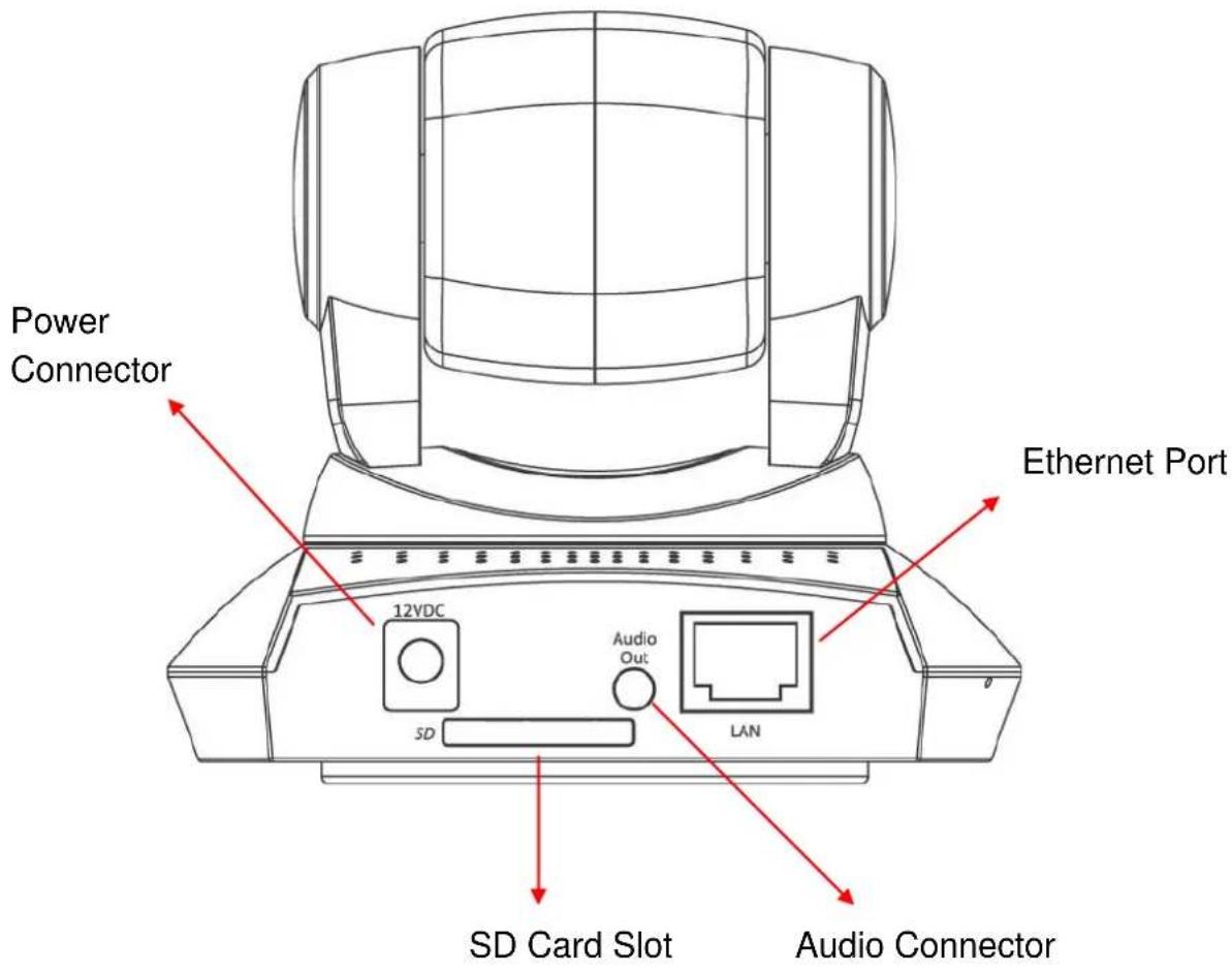
| Item | Description |
| Power Connector | Connects to 12V DC power adapter |
| SD Card Slot | Accepts SD / SD-HC memory card for image / video storage |
| USB Port* (IC-7010PT only) | Accepts USB WiFi adapter** to enable wireless |
| Audio Connector | Connects to external speaker for audio output |
| Ethernet Connector | Connect to your local area network |
| Antenna Base (IC-7010PTnonly) | Connects to supplied antenna |
| WPS Button (IC-7010PTn only) | Press the WPS button (click) on the IP Cam and click on the Access Point that you want to wirelessly connect it to. |
Note: The USB port only works with Edimax USB WiFi adapters.
| Item | Description |
| Reset Button | Press the button with pen nib and hold for 5 seconds to reset the camera settings to factory default value. |
Bottom View
natural_image
Technical diagram of a mechanical component with red arrows indicating direction, no text or symbols presentTripod Connector
| Item | Description |
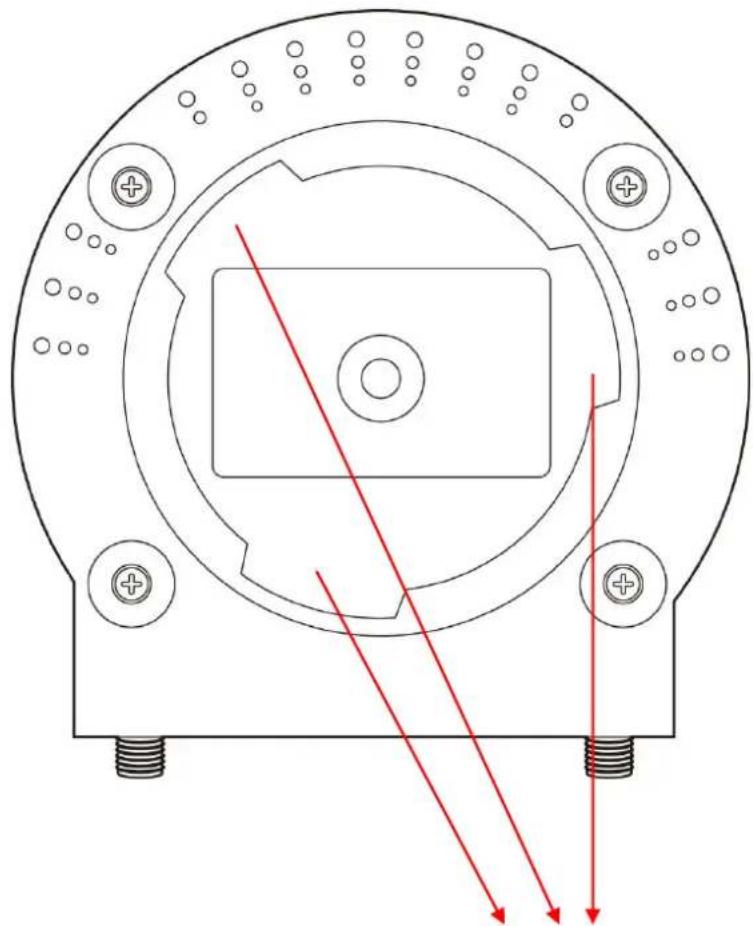
| Tripod Connector | Connects to tripod to secure the camera when the camera is not put on a horizontal surface. |
1.5 Camera Installation
Please follow the following instructions to set your IP camera up.
-
Unpack the product package and check if anything's missing.
-
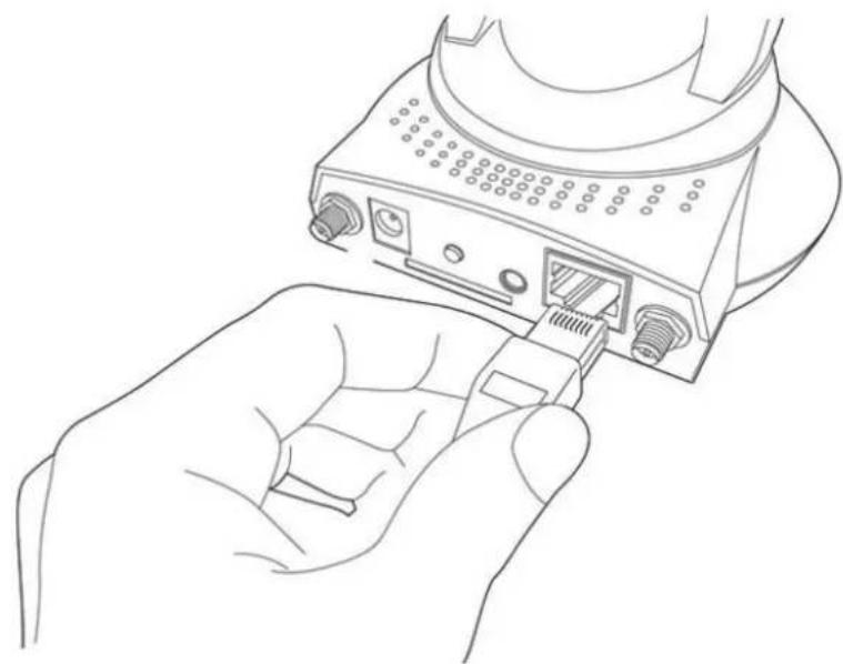
Connect the Ethernet cable to your local area network, and connect the other end to the LAN jack of this IP camera.
natural_image
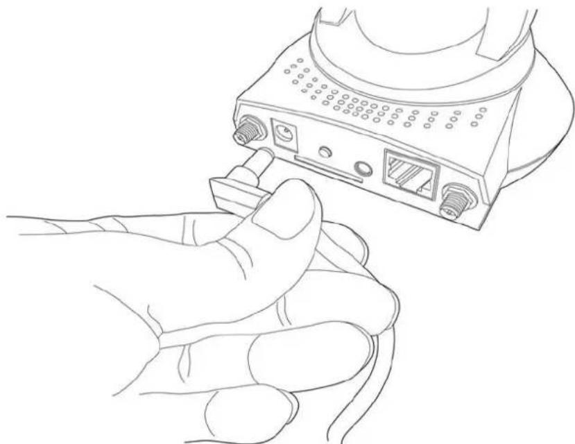
Line drawing of a hand inserting a USB into a device (no text or symbols)- Plug the power adapter to wall socket, and connect the power connector to the power jack located at the bottom of the IP camera.
natural_image
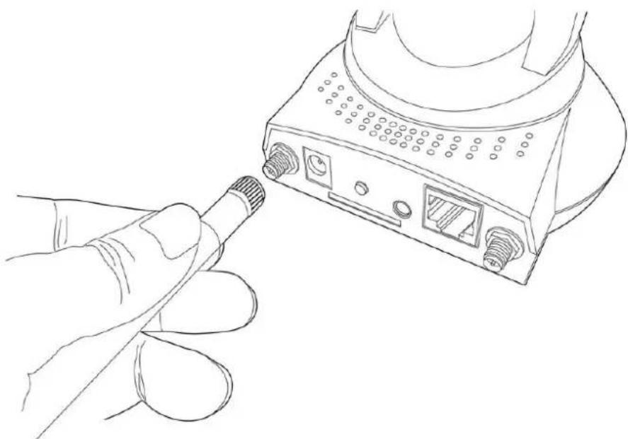
Line drawing of a hand inserting a USB into a device (no text or symbols)- Connect two antennas to the antenna bases, which is located at the back of this IP camera.
natural_image
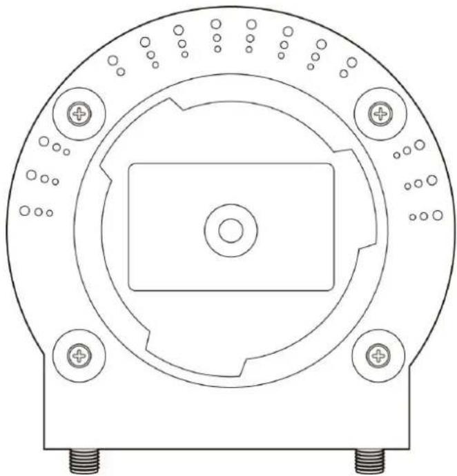
Line drawing of a hand holding a connector to a device with ports and connectors (no text or symbols)- Place the camera at a secure place, and point the camera to the place you wish to monitor. If you wish to hang the camera on the ceiling or wall, please use the tripod connector (located at the bottom of the camera) to secure the camera.
natural_image
Technical line drawing of a mechanical component with concentric circular features and mounting holes (no text or symbols)- Launch Internet Explorer on your computer, and following the instructions given in next section to set the IP camera.
1.6 Locate the IP Address of this IP Camera
Default IP address of this IP camera is 192.168.2.3. If you wish to assign another IP address to this IP camera, you have to log onto the web configuration interface of the camera first.
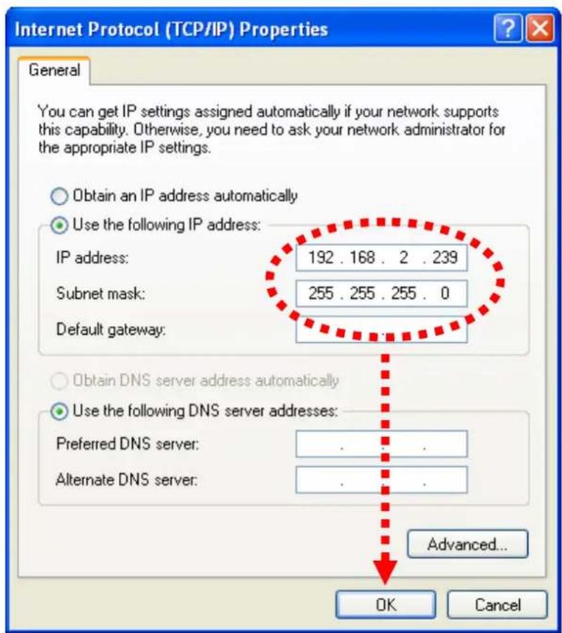
If the left three fields of the IP address of your computer is not 192.168.2, you'll have to change the IP address of your computer first:
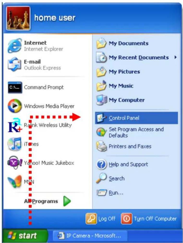
1. Click 'Start' -> 'Control Panel'
2. Double-click 'Network Connections' icon.
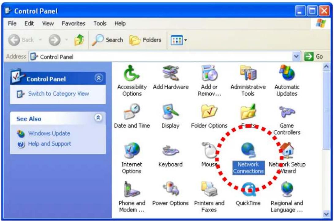
3. Right-click 'Local Area Connection', and click 'Properties'.
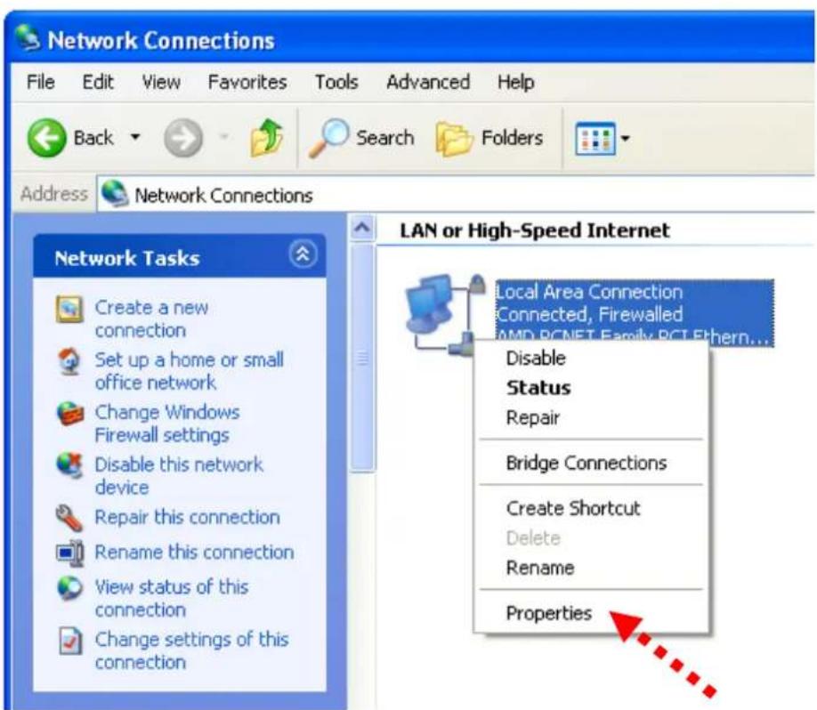
- Select 'Internet Protocol (TCP/IP)', then click 'Properties'.
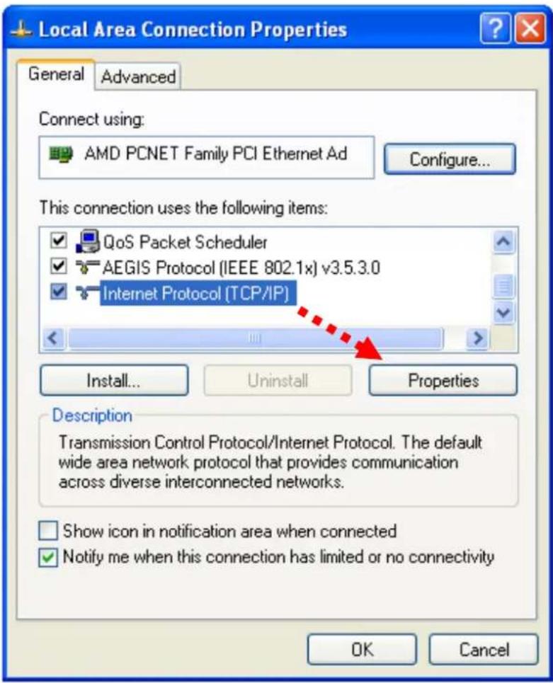
- In 'IP address' field, please fill in any IP address begins with '192.168.2', and ends with a value greater than 2 and less than 254 (You can use the example in the picture '192.168.2.339'). In Subnet mask field, please fill '255.255.255.0'. Please keep all other fields empty, and click 'OK'.
If you changed the IP address of this IP camera and you forget it, there're 2 methods to recover it:
a. Press and hold the 'Reset' button located at the bottom of this IP camera, to clear all settings of the IP camera and reset the IP address back to 192.168.2.3. You'll lose all settings in the IP camera.
b. Ask network administrator to check the DHCP release table, if the camera was set to obtain the IP address by DHCP, a new record will be added to DHCP release table on DHCP server when the IP camera is connected to the local area network.
1.7 Using Camera Admin Software to Locate Camera
If you can't connect to the camera by the instructions given in last chapter, you can use camera admin software to search the camera which is connected to your local area network. The admin software is also capable to locate multiple cameras on your local area network.
Please insert the user manual CD-ROM supplied in the product package, and the CD will automatically running the installation, if not please double-click 'Setup_Admin_3.0.17' icon:
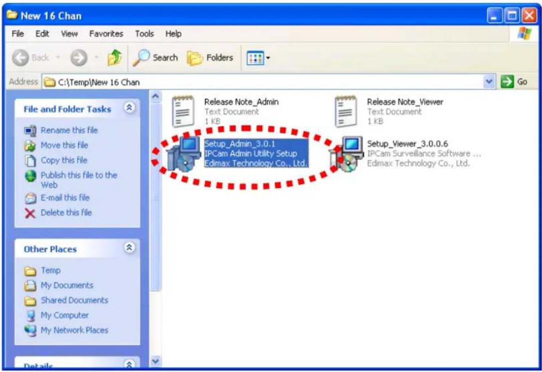
Then follow the following instructions to install and use camera admin software:
- Click 'Next' to start install camera admin software:
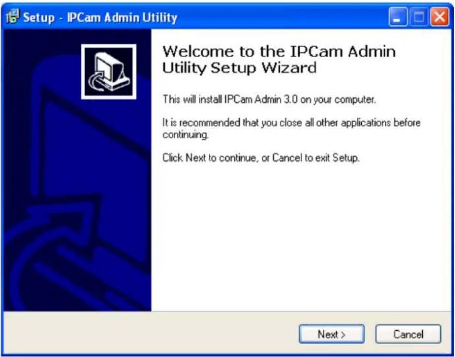
- You can change the installation folder of camera setup software here, click 'Browse' to select an existing folder, or you can just click 'Next' to use default installation folder:
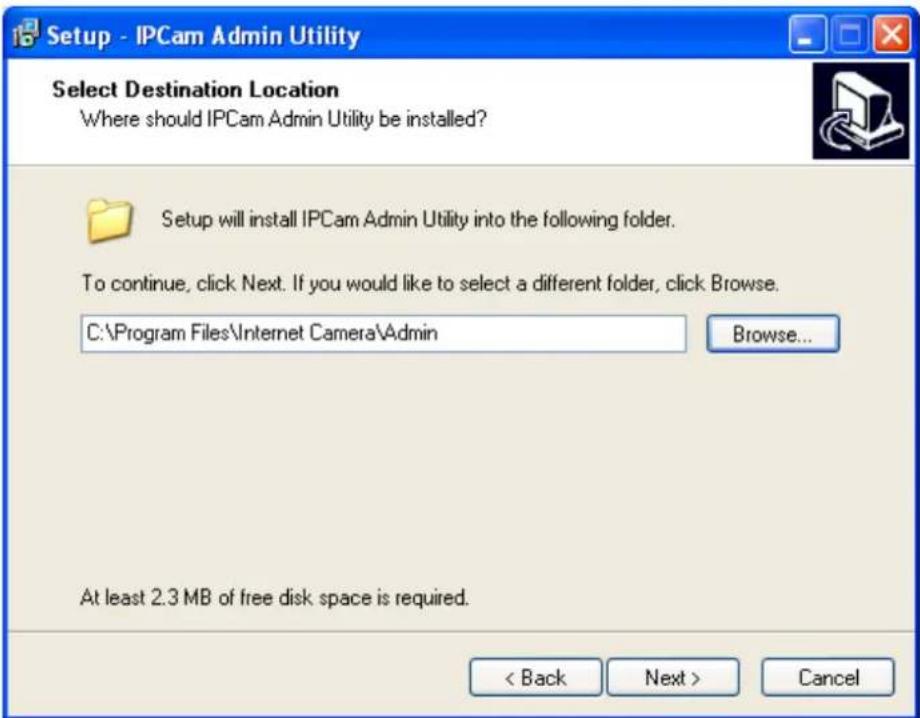
- If you wish to create desktop icon and / or quick launch icon for camera admin software, please check corresponding box, and click 'Next' to continue.
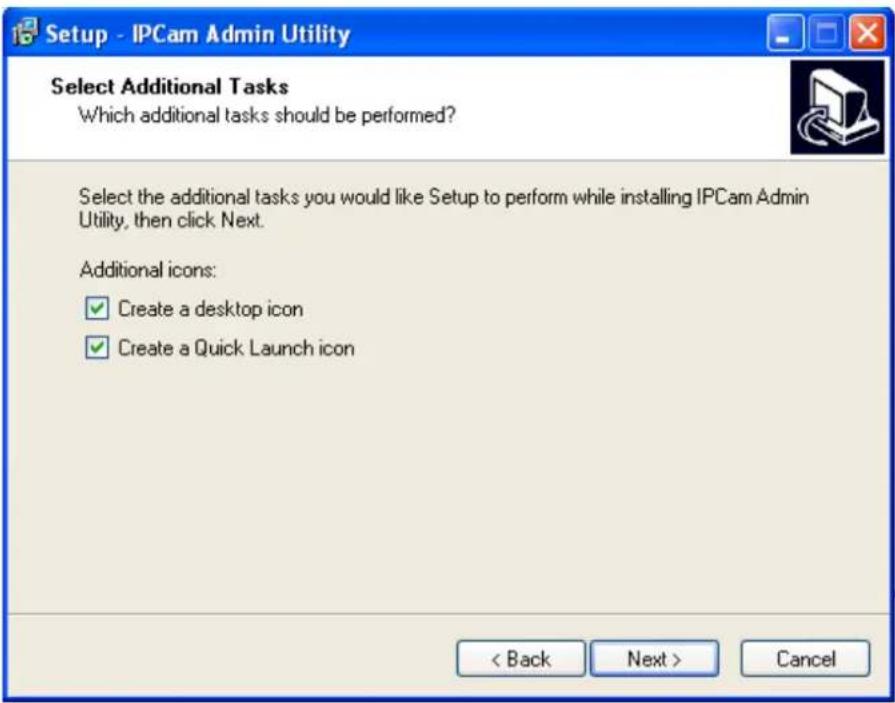
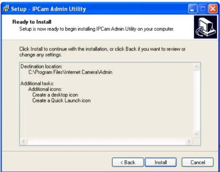
- You'll see a brief of all options you selected, click 'Install' to install camera admin software now, or click 'back' to back to previous steps to change settings.
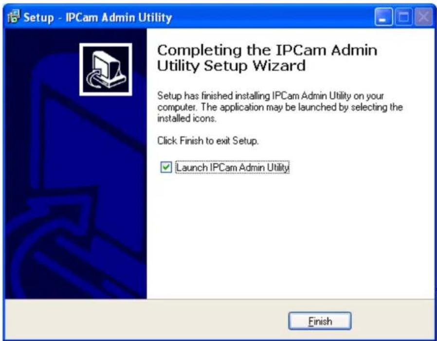
- When you see this message, the installation of camera admin software is complete. If you wish to launch camera admin software now, keep 'Launch IP Cam Admin Utility' box checked, and click 'Finish' to close installation utility.
After the camera admin software is launched, all cameras found on your local area network will be displayed:
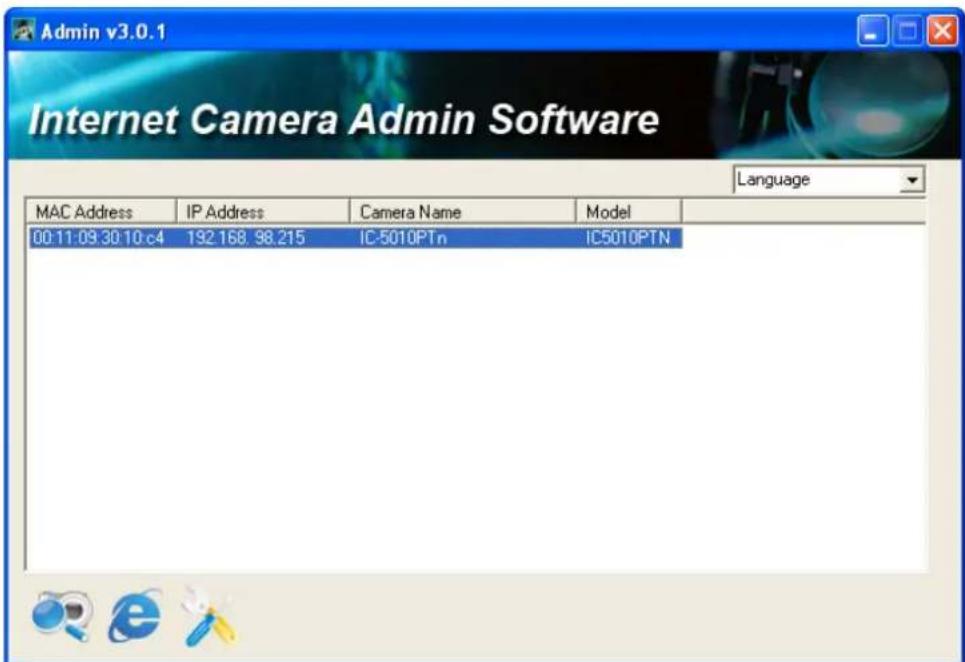
All camera-related information will be displayed here. If you wish to connect to certain camera by web browser, double-click the camera listed here.
The camera admin software also provides several functions:
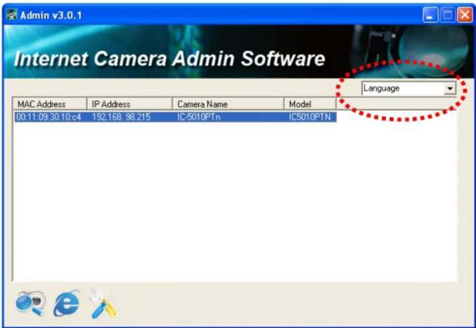
Language change: This camera admin software supports 3 languages: English, Chinese, and Japanese. You can select the language you wish to use from language dropdown menu located at upper-right corner of camera admin software.

Search camera: Click this button to search all cameras on local area network again.

Browse camera via web: Select a camera listed above first, and then click this button to connect to the camera by web browser.

Configure camera: Click this button to configure camera's network and security setting. You'll be prompted to input camera's password:
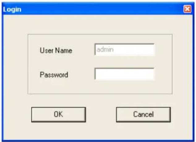
Input the password (default: 1234) and click OK to configure the camera's network and security setting:
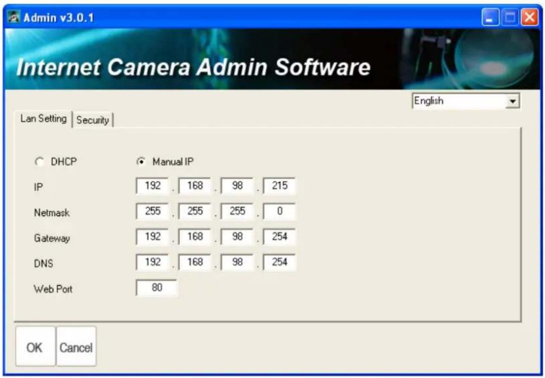
In ‘Lan Setting’ page, you can configure camera’s network settings. Select ‘DHCP’ to set the camera to obtain an IP address from DHCP server on local area network automatically, and select ‘Manual IP’ to input the IP address information manually. Click ‘OK’ to save settings.
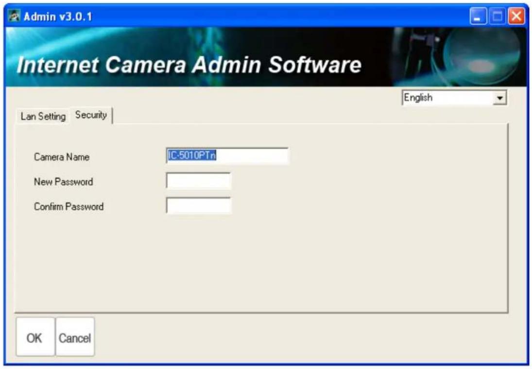
In ‘Security’ page, you can change the camera’s name and password (user name is always ‘admin’ and cannot be changed). You have to input the same password in both ‘New Password’ and ‘Confirm Password’ field, or you’ll be prompted to input new password again. Click ‘OK’ to save settings or click ‘Cancel’ to discard changes.
1.8 Log Onto Web Management Interface
Make sure the IP camera is correctly powered (Power LED is on), and then launch Internet Explorer and type the IP address of the IP camera in address bar of Internet Explorer. You should be prompted to input the user name and password:
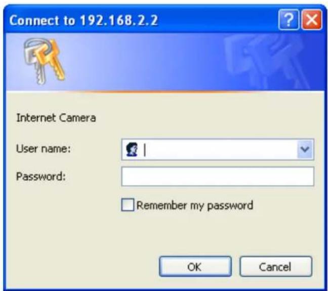
Default user name is 'admin' and password is '1234'. Click 'OK' to continue after user name and password has entered.
If you're rejected, maybe the password has been modified previously. This should not happen if this is a newly-purchased camera, however, if you get the camera from someone else, the password would be changed. Please try to obtain the correct user name / password, or you'll have to reset the camera.
If this is the first time you log onto web management interface, you'll be prompted to install ActiveX Plugin:
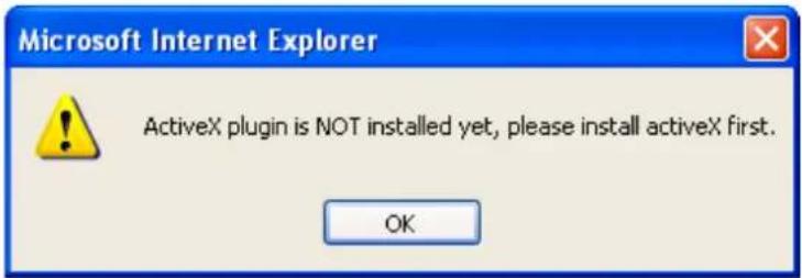
When you see this message, please click 'OK', and click 'Download the latest ActiveX' link to download plugin so you can use this camera:
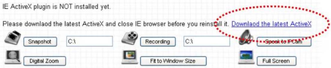
Click 'Run' to download plugin:
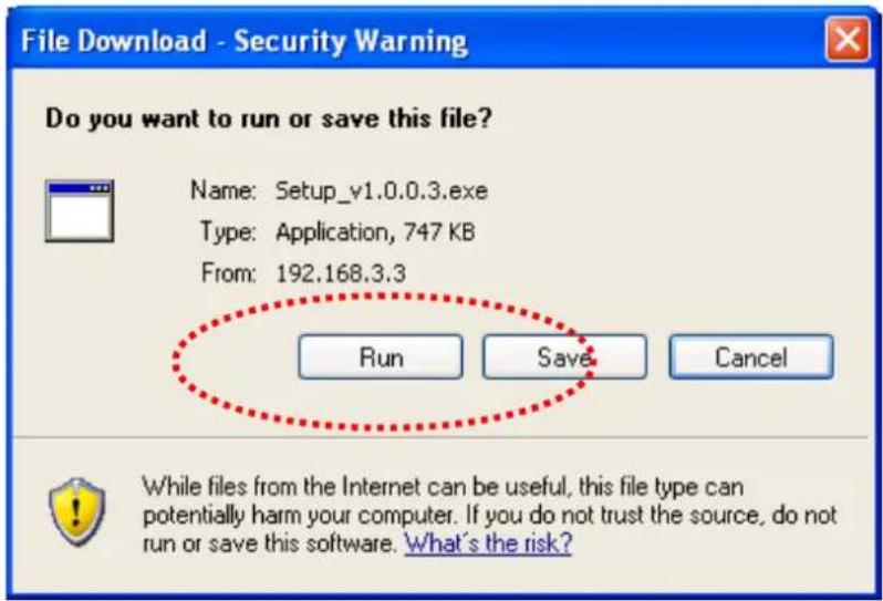
Click 'Run' to install plugin:
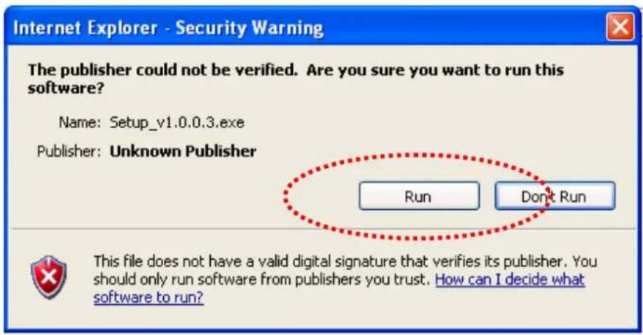
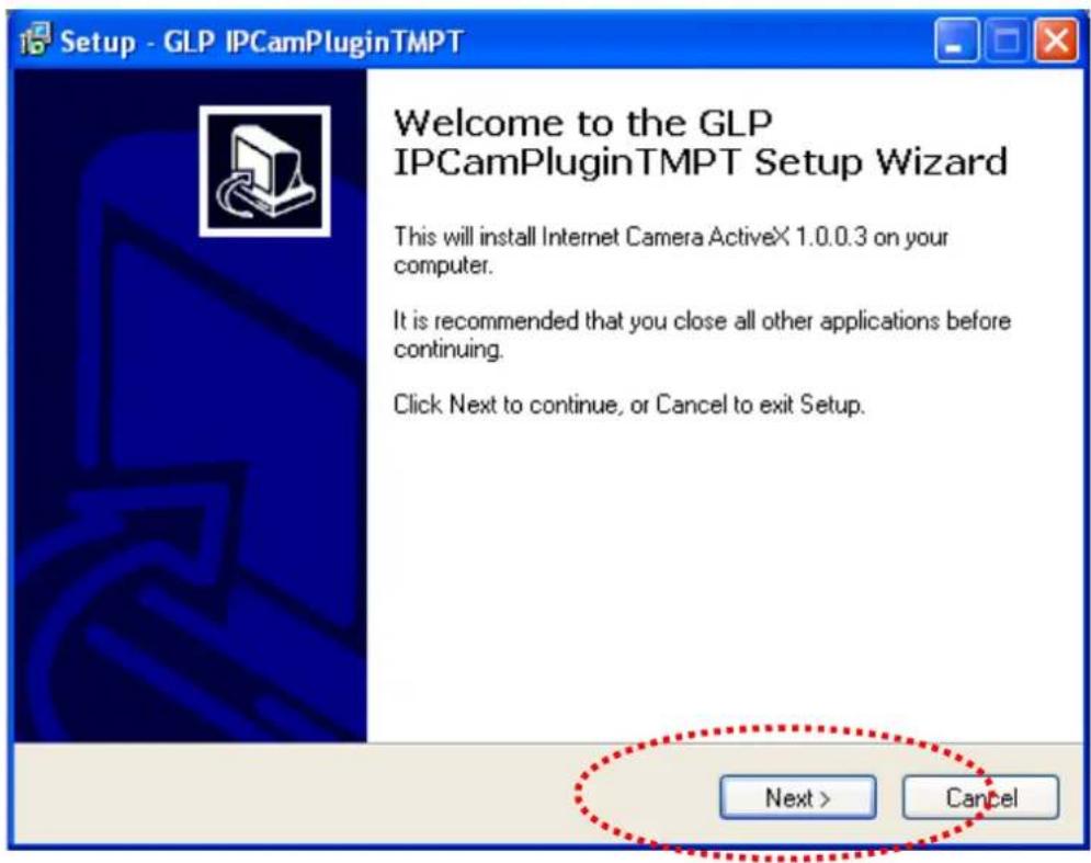
Please click 'Next' button to start installation (click 'Next' or 'Install' when you're prompted, until installation is complete).
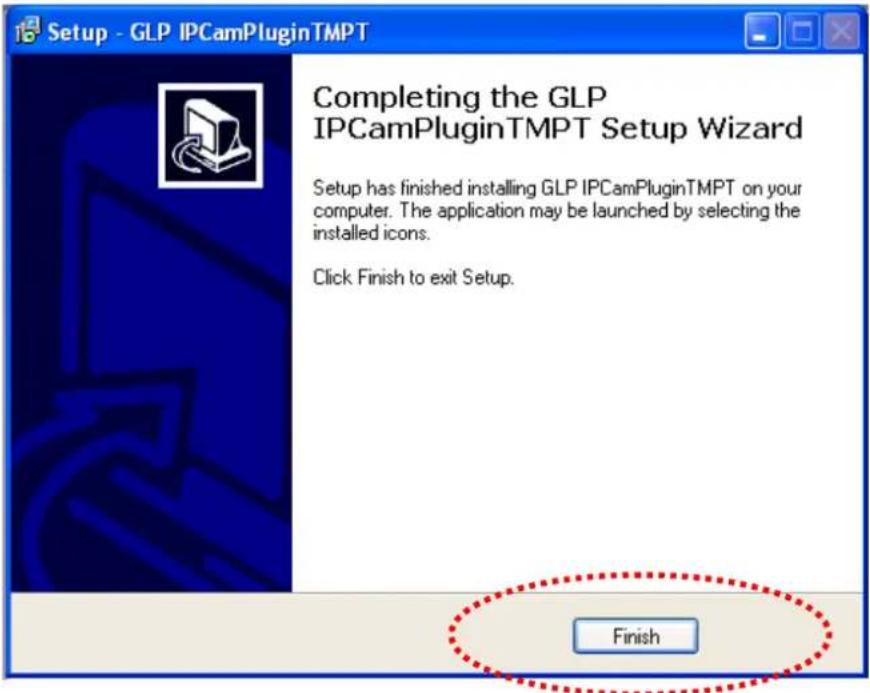
Click 'Finish' to complete plugin installation.
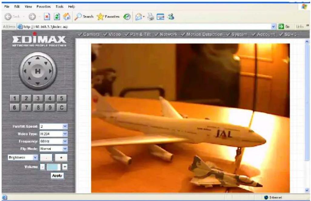
Now you can go back to web browser, and you should be able to see the image captured by camera (You may need to press F5 or CTRL-R to reload web page).
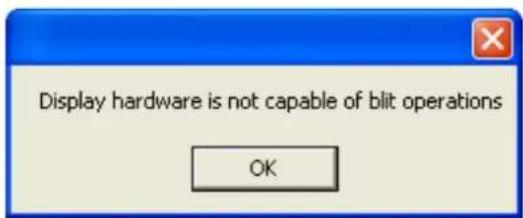
Note: If you see one of these messages (or both):
OR
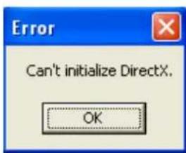
Your computer may not have the display capability that this IP camera requires, or you don't have Microsoft DirectX® installed. Please download Microsoft DirectX® from Microsoft's website (http://www.microsoft.com), and try again.
In some cases, your computer is able to display the image from IP camera correctly, but you'll still see these messages. If this happens, just ignore them.
Chapter II: Using Web Management Interface
2.1 Camera Settings
The first menu after you logged onto web management interface is 'Camera', and this is the only menu you can see the real-time image from camera.
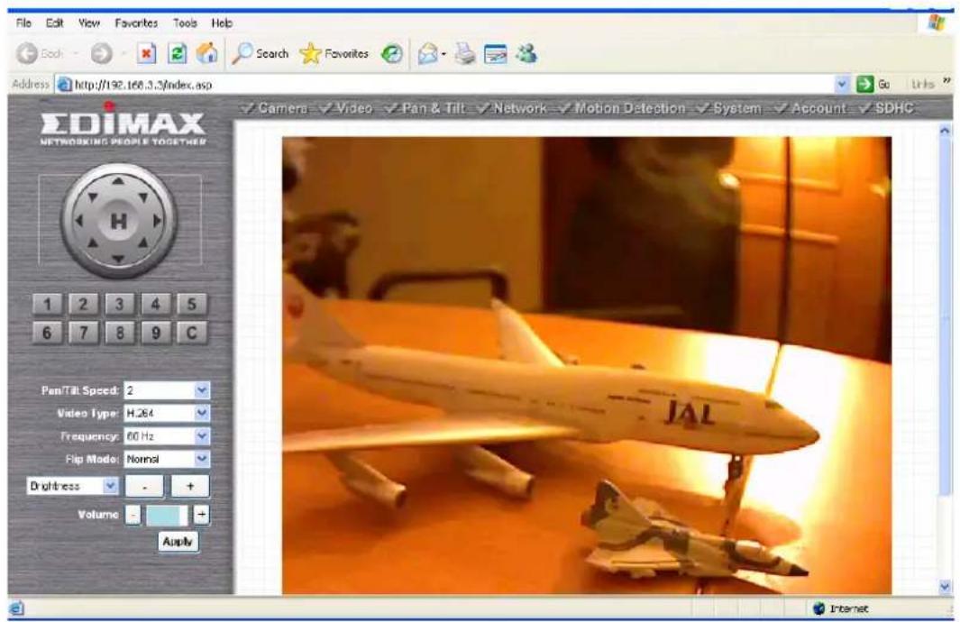
You can always back to this menu by clicking 'Camera' on the top of web management interface.

The descriptions of every setting in this menu will be given below:
| Item | Description |
| Pan/Tilt Speed | Specifies the moving speed when you use pan / tilt function to point the camera to a new direction. Available options are 1 (fastest) to 5 (slowest). Select 1 to move the camera by a faster speed, but you will not be able to control the movement precisely. If you want to move the camera in a more accurate manner, select a slower speed. |
| Video Type | Specifies video encoding type. Available options are ‘MPEG4’, ‘MJPEG’, and ‘H.264’. Different encoding type requires different bandwidth, and provides different video quality. |
| Frequency | If the place where this IP camera points to has a (or more) fluorescent light(s), the image may look flashing. In this case, you can adjust this setting to the frequency of electrical power; this can improve the image quality effectively. If you don’t know which one you should use, just try any of them and select one with less flicker. |
| Flip Mode | If you’re not putting this camera on a horizontal surface but hang the camera on the ceiling or wall, you can use this function to rotate the displaying image. |
| Brightness / Saturation / Sharpness | Select brightness, saturation, and sharpness from dropdown menu, and click ‘-’ or ‘+’ button to increase or decrease brightness / saturation / sharpness setting value. In certain environment, adjust brightness, saturation, and / or sharpness will help improve video quality. |
| Volume | Adjust the volume of audio output. Press ‘+’ or ‘-’ button to increase or decrease volume. |
| NOTE: When you change any setting(s) listed above, please click ‘Apply’ button so the change(s) will take effect. For following functions, changes will take effect right away. | |
Pan / Tilt Control 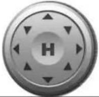 | Moves camera to a new direction. Press one of 8 directional buttons to move the camera, and press ‘H’ to move the camera back to ‘home’ (original) position. |
Preset Points 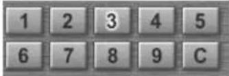 | You can set up to 9 preset points of camera position; press the number to move the camera to preset point instantly. See next chapter for detail instructions of how to set preset points.Press ‘C’ and the camera will cruise between all preset points automatically. |
Snapshot  Snapshot Snapshot | Click ‘Snapshot’ button to save the displaying image as an image file, a message box will appear after you click ‘Snapshot’ button, showing the filename and location of saved image file (default filename is current date and time).Default directory used to save image file is ‘C:\’, you can change the directory by clicking the text input box located at the right of ‘Snapshot’ button: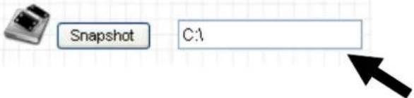 and you’ll be prompted to select a new directory. and you’ll be prompted to select a new directory. |
Recording  Recording Recording | Press this button to record the displaying image as a video file in AVI format, and you can play the video file back by Windows Media Player. To stop recording, press ‘Stop Recording’ button (the same button). You can also change the directory used to save video file. |
Speak to IP Cam  Speak to IPCam Speak to IPCam | You can transmit the voice received by your computer’s microphone to the camera’s external speaker. Press and hold this button, then speak to the microphone. Please note that external speaker must be connected to this camera. |
| Digital Zoom | If you wish to enlarge certain portion of the captured |
 Digital Zoom Digital Zoom | image, you can click this button to set digital zoom: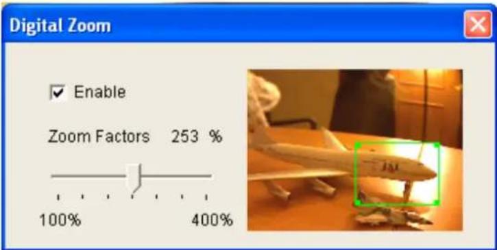 Click ‘Enable’ to enable digital zoom function, then you can drag the slide bar to adjust zoom ratio. You can also use your mouse to drag the zoom area (the green square) to reposition the zoom area. Click ‘Enable’ to enable digital zoom function, then you can drag the slide bar to adjust zoom ratio. You can also use your mouse to drag the zoom area (the green square) to reposition the zoom area. |
Fit to Window Size Fit to Window Size Fit to Window Size | Click this button and the image size will be adjusted to fit the size of browser window. |
Full Screen Full Screen Full Screen | Click this button to display the image in full-screen mode (uses all available space to display the image captured by this camera). |
2.2 Video
You can change video-related settings of this IP camera in 'Video' menu. You can access this menu by clicking 'Video' on the top of web management interface.

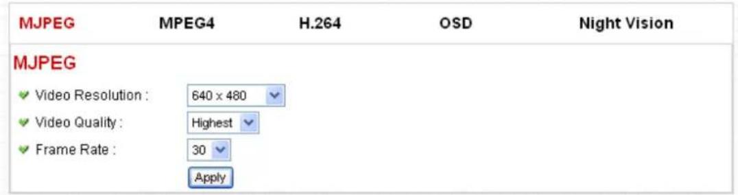
There are 5 types of video settings for this IP camera. To set the option of a certain video setting, put mouse cursor on it and its options will appear.
Video
2.2.1 MJPEG
You can adjust video settings when you select 'MJPEG' as video type in 'Camera' menu.
MJPEG
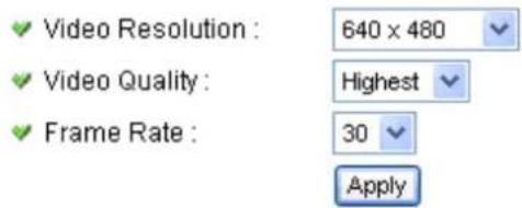
The descriptions of every setting in this menu will be given below:
| Item | Description |
| Video Resolution | Changes the resolution of video. Available options are 1280 x 1024, 640 x 480, and 320 x 240. Higher resolution provides better video quality and more detail, but requires more network bandwidth. |
| Video Quality | Changes video quality. There are 5 levels of video quality from ‘Lowest’ to ‘Highest’. Selecting a higher video quality will provide better video quality, but requires more network bandwidth. |
| Frame Rate | Changes video frame rate. Available options from ‘30’ to ‘1’, indicates how many video frames this camera will transmit every second. Higher frame rate provides smooth video watching experience and will not lose details of video, but requires more network bandwidth. If you’re using this video camera with insufficient network bandwidth, selecting a lower frame rate setting will help. |
Click 'Apply' for settings to take effect.
2.2.2 MPEG4
You can adjust video settings when you select 'MPEG4' as video type in 'Camera' menu.
MPEG4
Video Resolution :
Video Quality :
√ Frame Rate :
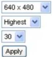
The descriptions of every setting in this menu will be given below:
| Item | Description |
| Video Resolution | Changes the resolution of video. Available options are 1024 x 768, 640 x 480, and 320 x 240. Higher resolution provides better video quality and more detail, but requires more network bandwidth. |
| Video Quality | Changes video quality. There are 5 levels of video quality from ‘Lowest’ to ‘Highest’. Selecting a higher video quality will provide better video quality, but requires more network bandwidth. |
| Frame Rate | Changes video frame rate. Available options from ‘30’ to ‘1’, indicates how many video frames this camera will transmit every second. Higher frame rate provides smooth video watching experience and will not lose details of video, but requires more network bandwidth. If you’re using this video camera with insufficient network bandwidth, selecting a lower frame rate setting will help. |
Click 'Apply' for settings to take effect.
2.2.3 H.264
You can adjust video settings when you select 'H.264' as video type in 'Camera' menu.
H.264
Video Resolution :
Video Quality:
√ Frame Rate :
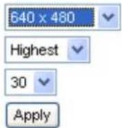
The descriptions of every setting in this menu will be given below:
| Item | Description |
| Video Resolution | Changes the resolution of video. Available options are 1280 x 1024, 640 x 480, and 320 x 240. Higher resolution provides better video quality and more detail, but requires more network bandwidth. |
| Video Quality | Changes video quality. There are 5 levels of video quality from ‘Lowest’ to ‘Highest’. Selecting a higher video quality will provide better video quality, but requires more network bandwidth. |
| Frame Rate | Changes video frame rate. Available options from ‘30’ to ‘1’, indicates how many video frames this camera will transmit every second. Higher frame rate provides smooth video watching experience and will not lose details of video, but requires more network bandwidth. If you’re using this video camera with insufficient network bandwidth, selecting a lower frame rate setting will help. |
Click 'Apply' for settings to take effect.
2.2.4 OSD
If you need to display information about this camera, like camera's name or current date / time, you can use OSD (On-Screen Display) menu:
On-Screen Display
√ On-Screen Display :
○ Enable ● Disable
Show Camera Name :
○ Enable ● Disable
Show Date :
- Enable ○ Disable
Show Time :
- Enable ○ Disable
Apply
The descriptions of every setting in this menu will be given below:
| Item | Description |
| On-Screen Display | Select ‘Enable’ to enable on-screen display function (information about this camera will be displayed on camera’s display image), and select ‘Disable’ to disable it. |
| Show Camera Name | Select ‘Enable’ to show camera’s name on camera’s display image, select ‘Disable’ to hide it. |
| Show Date | Select ‘Enable’ to show current date on camera’s display image, select ‘Disable’ to hide it. |
| Show Time | Select ‘Enable’ to show current time on camera’s display image, select ‘Disable’ to hide it. |
Click 'Apply' for settings to take effect.
When OSD is enabled, selected OSD items will be displayed like this:

2.2.5 Night Vision
This camera equips with 9 IR LEDs to enhance video quality in the night. You can enable or disable IR LEDs by 'Night Vision' menu:
IR Control
Always turn off IR led
○ Always turn on IR led
Auto mode
Turn on/off IR led by schedule
Turn on IR led from :
√ Turn off IR led from :
Apply
The descriptions of every setting in this menu will be given below:
| Item | Description |
| Always turn off IR led | Do not use IR LEDs, even it's very dark. |
| Always turn on IR led | Turn IR LEDs on, even it's very bright. |
| Auto mode | Let camera decide to switch LED lights on or off automatically: LEDs will light up when it's too dark. If you don't know which option you should select in this page, select this one. |
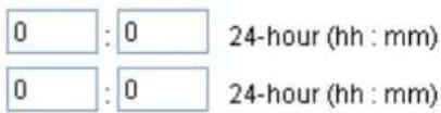
| Turn on/off IR led by schedule | Switch IR LEDs on or off by schedule. You have to input start time in ‘Turn on IR led from’ section, and end time in ‘Turn off IR led from’ section. |
Click 'Apply' for settings to take effect.
2.3 Pan and Tilt
This IP camera supports pan and tilt function, as you explored in last section. You can also make the camera move automatically in pan and tilt menu by defining a set of pre-defined path.
You can access this menu by clicking 'PTZ' on the top of web management interface.

flowchart
graph LR
    A["Camera"] --> B["Video"]
    B --> C["Pan & Tilt"]
    C --> D["Network"]
    D --> E["Motion Detection"]
    E --> F["System"]
    F --> G["Account"]
    G --> H["SDHC"]
2.3.1 Preset Points
You can define the camera position and save the position so you can recall the position later again. This camera provides 9 memory slots; follow the following instructions to move the camera and set a new preset point:
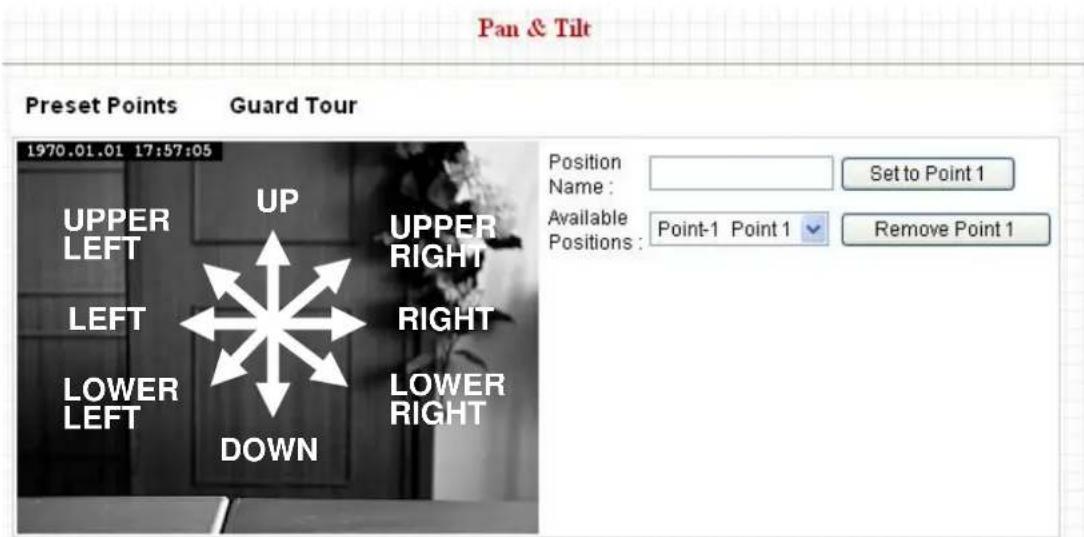
- Select a memory slot from 'Available Positions' dropdown menu first.
-
To move the camera, click the position of labeled text (not shown on image) on the image to move the camera to the direction. You may need to set the Pan / Tilt speed to a slower setting, so you can move the camera in a more accurate manner.
-
When you move the camera to the position you want, type a name in 'Position name' field, and click 'Set to Point n' (where 'n' is the number of memory slot) button to save the position to selected memory slot.
After you set the position, you can recall the position from 'Camera' menu (click the position number button), and the camera will move to preset position instantly.
If you want to remove a preset position, select the memory slot from 'Available Positions' dropdown menu, and then click 'Remove Point n', (where 'n' is the number of memory slot you wish to clear position setting).
2.3.2 Guard Tour
You can make the camera move between many pre-defined positions, and define the time you wish to pause at every position; this is called as 'Guard Tour'.
Guard Tour
Guard Tour List:
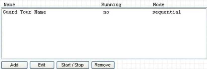
Before you can use this function, you have to define at least 2 positions in 'Preset Points' section (refer to last section for detailed information).
The descriptions of every setting in this menu will be given below:
| Item | Description |
| Add | Add a new set of guard tour (see instructions below) |
| Edit | Edit a selected guard tour. The parameters for an existing guard tour will be recalled and you can modify them. |
| Start / Stop | Select a guard tour and click this button to start guard tour, click again to stop it. After a guard tour has been started, go to ‘Camera’ menu to see it in action. Only one guard tour can be activated at the same time. |
| Remove | Remove a guard tour from the list. |
If you wish to add a new set of guard tour, click 'Add' to start to add a new guard tour set:
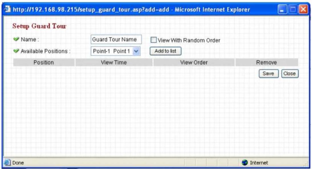
The descriptions of every setting in this menu will be given below:
| Item | Description |
| Name | Input the name of this set of guard tour here. As you may have many sets of guard tour, please give it a meaningful name so you can remember the main purpose of this set. |
| View with random order | Do not visit all positions in this guard tour by order; visit them randomly instead. |
| Available positions | Select preset points from dropdown menu here, then click ‘Add to list’ to add this position to this guard tour.When you click ‘Add to list’, you’ll be prompted to set these parameters: 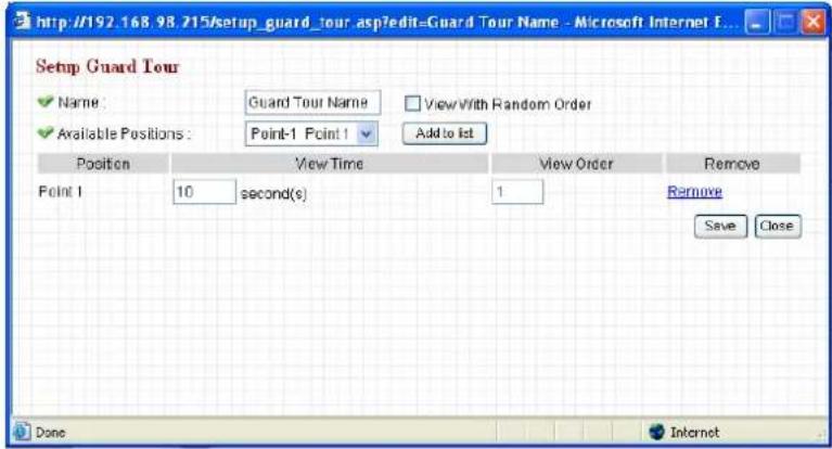 View Time: Define the time you wish the camera to stop at this position in seconds.View Order: Give this position a number greater than 1 and not the same with other positions, and guard tour will start visiting positions by order (from 1 to last number, and then start from 1 again).Remove: Remove this position from list.Save: Save settings for this position.Close: Close this window and discard all changes. View Time: Define the time you wish the camera to stop at this position in seconds.View Order: Give this position a number greater than 1 and not the same with other positions, and guard tour will start visiting positions by order (from 1 to last number, and then start from 1 again).Remove: Remove this position from list.Save: Save settings for this position.Close: Close this window and discard all changes. |
2.4 Network Settings
All network-related settings can be found in this menu, and you have to specify TCP/IP parameters in this menu if you want to change IP address, use PPPoE, Dynamic DNS, and activate UPnP function.
You can access this menu by clicking 'LAN' on the top of web management interface.

flowchart
graph LR
    A["Camera"] --> B["Video"]
    B --> C["Pan & Tilt"]
    C --> D["Network"]
    D --> E["Motion Detection"]
    E --> F["System"]
    F --> G["Account"]
    G --> H["SDHC"]
After you selected 'Network', network setting menu will appear. There are 6 sub-menus available here:
| Network | |||||
| LAN | WLAN | Dynamic DNS | UPnP | LoginFree | RTSP |
Please click the network setting you wish to set, and then refer to instructions given below:
2.4.1 LAN
You can define IP address and select the port number you wish to use here.
LAN
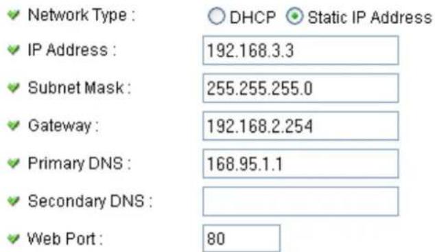
PPPoE
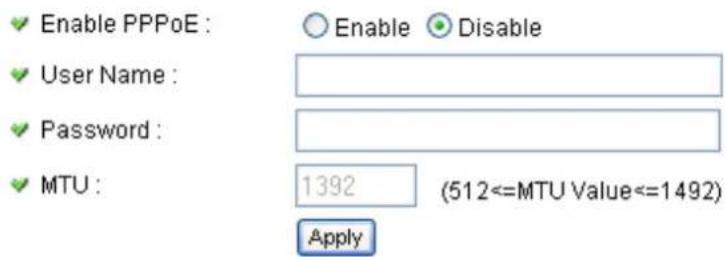
The descriptions of every setting in this menu will be given below:
| Item | Description |
| Network Type | This camera can obtain the IP address from DHCP server automatically (if you have one), or set a fixed IP address. Select ‘DHCP’ to obtain IP address automatically or ‘Static IP Address’ to assign this IP camera with a fixed IP address.When ‘DHCP’ is selected, IP address parameters below will be grayed out. |
| IP Address | Specify the IP address for this IP camera here. |
| Subnet Mask | Specify the subnet mask for this IP camera here. |
| Gateway | Specify the gateway address of the local network here. |
| Primary DNS | Specify the IP address of DNS server here. Please input IP address only. If you don’t know the address of DNS server, ask network administrator or your ISP for help. |
| Secondary DNS | Specify the IP address of backup DNS server here. When primary DNS is unreachable, IP camera will use the IP address specified here as DNS server.This field is optional. |
| Web Port | Specify the port number of web management interface here. If it’s not 80, you’ll have to add ‘:port’ after the IP address / hostname of this IP camera.For example, if the HTTP port number you specified here is 90 and the IP address of IP camera is 10.20.20.30, then you have to input ‘http://10.20.20.30:90’ in the address bar of Internet explorer. |
| Enable PPPoE | Select ‘Enable’ to activate PPPoE function of this IP camera, select ‘Disable’ to disable it. |
| User Name | Input the PPPoE username assigned by your ISP here. |
| Password | Input the PPPoE password assigned by your ISP here. |
| MTU | Input the MTU (Maximum Transmission Unit) given by your ISP here. Ask your ISP if you don’t know what value you should input here. Default value should work with most of ISPs and will give you a nice network |
performance.
Click 'Apply' to save settings and make the new settings take effect.
2.4.2 WLAN
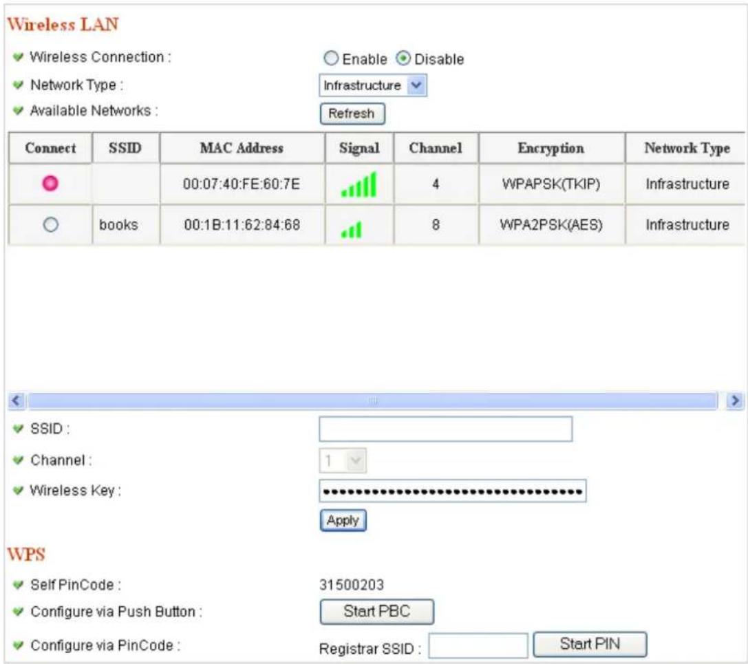
The descriptions of every setting in this menu will be given below:
| Item | Description |
| Wireless Connection | Select ‘Enable’ to activate wireless network function of this IP camera, select ‘Disable’ to disable it. |
| Network Type | Select the network type of wireless connection.Available options are ‘Infrastructure’ (Connect the IP camera to a wireless access point), and ‘Adhoc’ (This IP camera will become a stand-alone wireless network point, other wireless computers / devices can discover this IP camera and connect to it without wireless accesspoint).You can set to ‘Adhoc’ when you don’t have any wireless access point, but your computer has wireless network card. Set to ‘Infrastructure’ when you have wireless access point, and you have computers with wired network connection. |
| Available Networks | Here shows all wireless access points found by this IP camera. Please note not all access points will be displayed at the same time, if the access point you expected to connect does not appear, you may have to click ‘Refresh’ button for several times until it appears.The descriptions of all fields is listed below:Connect: You can select the wireless access point you wish to connect here.SSID: the SSID of all found wireless access points will be shown here. Some wireless access point may hide their SSID; in this case, you have to identify them by their MAC address.MAC Address: If you there are many wireless access points in proximity or some wireless access point hides it’s SSID, you can use MAC address to distinguish them. Signal: Shows the radio signal strength in percent. Channel: Shows the radio channel of this wireless access point.Encryption: Shows the encryption type used by this wireless access point. You must use the same encryption type if you wish to connect to a certain wireless access point. If the wireless access point does not use encryption, ‘Disabled’ will be displayed here.Network Type: Shows the network type of a certain wireless access point (Infrastructure or Adhoc). |
| SSID | Input the SSID of the wireless access point you wish to connect. It should be less than 32 alphanumeric characters.When you select a wireless access point above, it's SSID will be filled in this field automatically. However, if the SSID is not displayed (the wireless access point you selected choose to hide it's SSID), you have to know it's SSID and input it here, or you will not be able to connect it. |
| Channel | Select the radio channel you wish to use here. When network type is ‘Infrastructure’, the radio channel is auto-selected according to the channel that wireless access point uses. You can only select the channel number when network type is ‘Adhoc’. |
| Wireless Key | Input the encryption key of selected wireless access point here. This is required when access point you wish to connect uses encryption. |
| Self PinCode | Here displays the WPS pin code used to connect to WPS-enabled wireless access points. You have to input this number into the WPS enabled access point to establish WPS connection. |
| Configure via Push Button | Click this button and this camera will enter PBC-style WPS connection state for 120 seconds. Please push ‘Start PBC’ button on the wireless access point you wish to connect within 120 seconds to establish WPS connection (The remaining time will be displayed on the button).If connection can not be established after 120 seconds, you’ll be prompted by a message box, and you can press ‘Start PBC’ button to try again. |
| Configure via PinCode | If you have wireless access point’s WPS PIN code, you can input it here and press ‘Start PIN’ button to start to establish PIN-style WPS connection. |
2.4.3 Dynamic DNS
If your ISP does not give you a fixed Internet IP address (i.e. the Internet address you're using when you access the Internet is not always the same – ask your ISP for detailed information), you can use this function to help you locate the IP address of this IP camera when you're away from home or office.
Before you can use this function, you'll need to apply for an account at dyndns.org (http://www.dyndns.org). Detailed instructions of how to apply a new account can be found on dyndns.org's website.
Dynamic DNS
Enable DDNS :
○ Enable ● Disable
Provider :
dyndns.org
Host Name :
ddns-host
User Name :
ddns-account
√ Password :
●●●●●●●●●●●●
Apply
The descriptions of every setting in this menu will be given below:
| Item | Description |
| Enable DDNS | Select ‘Enable’ to activate Dynamic DNS function of this IP camera, select ‘Disable’ to disable it. |
| Provider | Select dynamic DNS service provider here. Only dyndns.org is available currently. |
| Host Name | Input dynamic DNS host name here. |
| User Name | Input dynamic DNS user name here, must be the same as the one you applied on dyndns.org. |
| Password | Input dynamic DNS password here, must be the same as the one you applied on dyndns.org. |
Click 'Apply' to save settings and make the new settings take effect.
2.4.4 UPnP
When UPnP function is activated, all UPnP-compatible computers / network devices will be able to discover this IP camera automatically (only those in the same local network).
This function is useful and you don't have to remember the IP address of this IP camera. Simply open 'Network neighbor' and it's there!
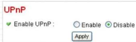
The descriptions of every setting in this menu will be given below:
| Item | Description |
| Enable UPnP | Select ‘Enable’ to activate UPnP function of this IP camera, select ‘Disable’ to disable it. |
Click 'Apply' to save settings and make the new settings take effect.
After UPnP function is activated, a popup message will appear:
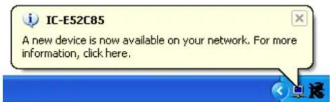
Click the message to open 'My Network Places', and you'll see the IP camera:
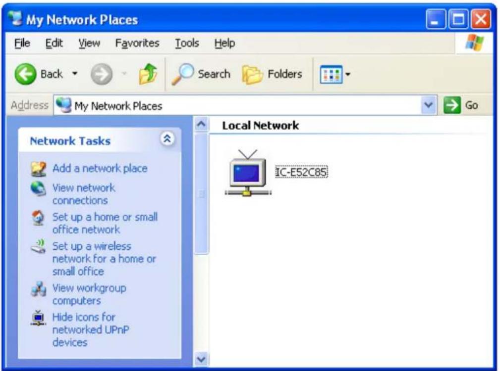
You can double-click the icon to launch Internet Explorer and log onto IP camera's web management interface directly.
2.4.5 LoginFree
This camera provides a method to let unauthorized users to view the image captured by this camera, which is called as 'LoginFree'. When you wish to let everyone to view the image captured by this camera, or integrate the image with your own web application, you can use this function:

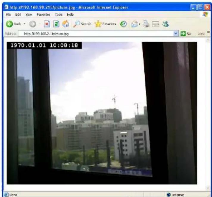
Input the filename here, and click 'Apply' to save settings, then other users can access the image by this filename with .jpg extension with the camera's IP address as prefix. For example, if your camera's IP address is '192.168.2.1' and the filename you set here is 'picture', then everyone on the web can access the image captured by this camera by using the following address:
http://192.168.2.1/picture.jpg
Please note that no authentication will be required to see the captured image. If you wish to disable this function, clear the text in 'Filename' field and click 'Apply.
2.4.6 RTSP
If you want to watch video captured by this IP camera by your own RTSP (Real Time Streaming Protocol) media player, you can use this function to setup RTSP parameters, so your RTSP-compatible player will be able to receive video data.
Video Streaming
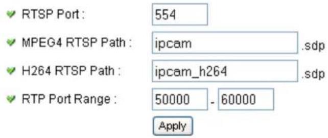
The descriptions of every setting in this menu will be given below:
| Item | Description |
| RTSP Port | Input the port number of RTSP here. Default setting is 554. |
| MPEG4 RTSP Path | Input the path of MPEG4 RTSP video file. When you use RTSP-compatible media player to play RTSP stream, please remember to add ‘.sdp’ file extension. |
| H.264 RTSP Path | Input the path of H.264 RTSP video file. When you use RTSP-compatible media player to play RTSP stream, please remember to add ‘.sdp’ file extension. |
2.5 Motion Detection
When you wish to use this camera to monitor the activities, motion detection function will be very useful. Camera will detect the motion in captured image, and take a snapshot when motion is detected. So you can use this camera to keep the safety of the belongings you have.
To use motion detection, click the following link from the top of menu:

flowchart
graph LR
    A["Camera"] --> B["Video"]
    B --> C["Pan & Tilt"]
    C --> D["Network"]
    D --> E["Motion Detection"]
    E --> F["System"]
    F --> G["Account"]
    G --> H["SDHC"]
After you selected 'Motion Detection', a sub-menu will appear. There are 5 sub-menus available here:
| Motion Detection | Motion Region | FTP Configuration | SD Card Configuration |
Detailed descriptions of every setting will be given below.
2.5.1 Motion Detection
You can use this menu to setup basic motion detection settings:
Motion Detection
√ Enable Motion Detection :
√ Motion Detection Interval :
Recording Time :
√ Sending File Type :
√ Send snapshot file to FTP :
√ Send snapshot file to E-Mail :
Enable Disable
5 seconds
3
JPEG
○ Enable ● Disable
○ Enable ● Disable
SD Card
SD Card Record :
√ Storage File Type :
Record File Size :
○ Enable ◦ Disable
Anonymous
The image contains no text or characters. It is a graphical element (a rectangular box) and does not contain any chart, graph, or data points that can be extracted into a markdown table.
The image contains no text or characters. It is a blank rectangular box with no visible content, figures, or markings. Therefore, there is no OCR result to generate.
192.168.3.61
share
JPEG
10 MBytes (Max 100 MB)
Apply Samba Test
The descriptions of every setting in this menu will be given below:
| Item | Description |
| Enable Motion Detection | Select ‘Enable’ to enable motion detection, and select ‘Disable’ to disable this function. |
| Motion Detection Interval | Select the time interval between two motions from dropdown menu. When a motion is detected, camera will not detect any motion again within the time interval you specified here. Available options are from 0 second (always detect new motion) to 60 seconds. |
| Recording Time | Select the duration you wish this camera to record image when a motion is detected from dropdown menu. Available options are 1, 2, 3, 4, and 5 (seconds). |
| Sending File Type | Select the file type that will be saved when a motion is detected. Select 'JPEG' and a still picture in JPEG format will be saved; and select 'AVI' to save a motion video clip. |
| Send snapshot file to FTP | Select 'Enable' to send the saved file to appointed FTP server when a motion is detected, select' Disable' to disable this function. You have to configure FTP server parameters in 'FTP Configuration' menu first, so this function will take effect (see below). |
| Send snapshot file to E-Mail | Select 'Enable' to send the saved file to appointed E-mail address when a motion is detected, select' Disable' to disable this function. You have to configure mail server parameters in 'FTP Configuration' menu first, so this function will take effect (see below). |
| SD Card Record | Select 'Enable' to record detected motion to SD card (if there's one), and select 'Disable' to disable this function. |
| Storage File Type | Select saving file type for motion detection: JPEG (still picture) or AVI MPEG4 / AVI H264 (for motion picture). |
| Record File Size | Input the maximum file size of saved file in Mbytes. Maximum file size is 100. |
| Record to Folder | Select 'Enable' to save file to a network folder which supports SAMBA (also known as 'Windows Network Neighborhood'), select 'Disable' to disable this function. |
| Authentication | If username and password are not required to write files in specified folder, select 'Anonymous'; if required, select 'Account'. |
| User Name | Input user name required by destination network folder. |
| Password | Input password of the user name required by destination network folder. |
| Samba Server | Input the IP address or host name of network file server. |
| Shared Folder | Input the folder name on file server. |
| Storage File Type | Select saving file type for motion detection: JPEG (still picture) or AVI MPEG4 / AVI H264 (for motion picture). |
| Record File Size | Input the maximum file size of saved file in Mbytes. Maximum file size is 100. |
Click ‘Apply’ to save settings and make the new settings take effect.
2.5.2 Motion Region
You can define the motion detection region within the image that camera captures, so this camera will ignore motions which are not covered by the motion region setting, and reduce the chances of false alarm.
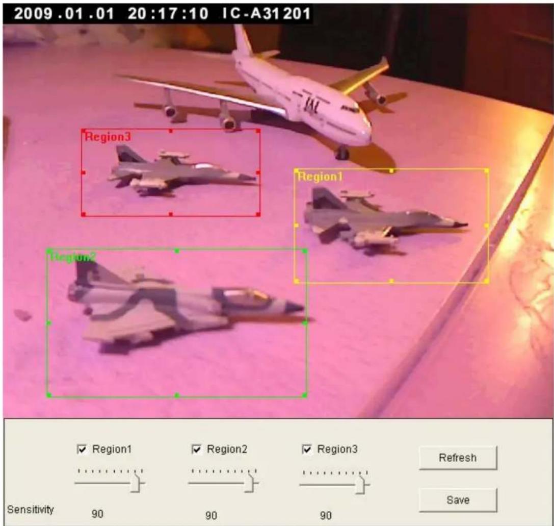
The descriptions of every setting in this menu will be given below:
| Item | Description |
| Region 1 – 3 | Check the box to enable motion detection region 1 to 3. You can check multiple boxes to enable multiple motion detection regions. When you checked a box, a new region (and region number) will be displayed on captured image. |
| Sensitivity | Move the slide bar to change the motion detection sensitivity setting: Drag the slide to the right to increase sensitivity (camera will detect minor changes in the image), and drag the slide to the left to decrease sensitivity (camera will only detect major changes in the image). |
| Refresh | In case the objects of the image captured by the camera moved, click this button to reload the image captured by camera, so you can decide the motion detection region more precisely. |
| Save | Save motion detection region settings. |
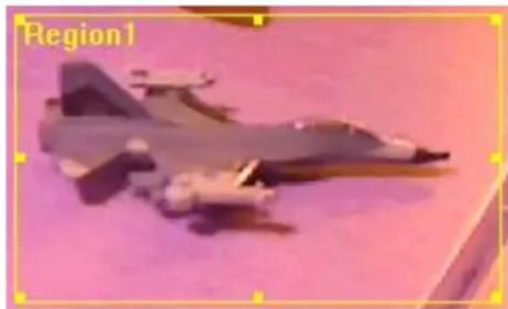
To change the motion detection region, you can ‘resize’ and ‘reposition’ it:
natural_image
Illustration of a military jet on a pink surface (no text or symbols visible)Move the mouse cursor to the eight dots located at the border of motion detection region, and the mouse cursor will switch to ↔ , ↘ , or ↓ . You can click and hold mouse button and move the mouse to resize the motion detection region.
To move reposition the motion detection region, move the mouse within the motion detection region, and the mouse cursor will switch to . Click and hold mouse button and move the mouse to reposition the motion detection region.
2.5.3 Email
You can define the destination address of E-mail sending and mail server parameters here.
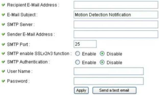
The descriptions of every setting in this menu will be given below:
| Item | Description |
| Recipient E-Mail Address | Input the email recipient's Email address here. |
| E-Mail Subject | Specify the title of sending email, so you can identify the mail sent from this camera from others quickly. |
| SMTP Server | Input the IP address or host name of the SMTP server (the server that delivers the Email for you) here.If you don't know, please refer to the SMTP server you're using in your Email software (like Outlook, Outlook Express etc.), or ask your network administrator or ISP. |
| Sender E-Mail Address | Input the Email address of mail sender, this will help you to identify the Email sent by this IP camera by sender's Email address.NOTE: Some mail server would reject to deliver the Email from unknown sender, it's recommended to input your own Email address here, or any other actual one. |
| SMTP Port | You can set port number according to your mail server. |
| SMTP enable SSLv2/v3function | Select 'Enable' if your SMTP server supports SSLv2/v3 such as gmail. |
| SMTP Authentication | Some SMTP server requires mail senders to be authenticated before they can send Email. If your SMTP server requires you to do so, please select ‘Enable’, or select ‘Disable’ to disable it. If you don’t know, please refer to the SMTP server you’re using in your Email software (like Outlook, Outlook Express etc.), or ask your network administrator or ISP. |
| User Name | Please input the user name of SMTP server here, if your SMTP server requires the use of authentication. |
| Password | Please input the password of SMTP server here, if your SMTP server requires the use of authentication. |
Click ‘Apply’ to save settings and make the new settings take effect.
After that, you can click 'Send a test email' to send a testing Email to the address you set here, so you can make sure the setting you specified here is correct and working.
2.5.4 FTP Configuration
You can set FTP server's parameters here.
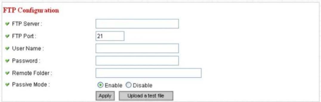
The descriptions of every setting in this menu will be given below:
| Item | Description |
| FTP Server | Input the IP address or host name of the FTP server you wish to use here. |
| FTP Port | Input the port number of the FTP server you wish to use here. |
| User Name | Input the user name of the FTP server you wish to use here. |
| Password | Input the password of the FTP server you wish to use here. |
| Remote Folder | Input the remote folder name on the FTP server here. If nothing is specified here, all uploaded image files will be placed in FTP server's root directory.Please ask FTP server's administrator to know which folder you should use. Certain user name may have restrictions and therefore can not place the file in the directory not owned by the user. |
| Passive Mode | Select ‘Enable’ to use passive mode to send file, or select ‘Disable’ to not to use passive mode to send file.Some FTP servers require passive mode, if you don't know, please ask FTP server's administrator; most of FTP servers will work fine with both modes, but if youfound that non-passive mode is not working, you can try to use passive mode. |
Click ‘Apply’ to save settings and make the new settings take effect.
After that, you can click 'Upload a test file' to send a file to the FTP server you set here, so you can make sure the setting you specified here is correct and working.
2.5.5 SD Card Configuration
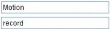
You can define the filename and destination folder when saving a file in SD card.
SD Card Configuration
Enable Cycle Recording
File Name Prefix :
√ Destination Folder :

The descriptions of every setting in this menu will be given below:
| Item | Description |
| Enable Cycle Recording | Check this box and this camera will automatically erase oldest image file to make rooms for new image files when SD card is full. If you don’t want to lose old image files, do not check this box. |
| File Name Prefix | Specify the filename prefix (the texts which will be added before the file sequence number). |
| Destination Folder | Specify the folder name that camera will store the saved image or video clip. |
Click 'Apply' to save settings and make the new settings take effect.
2.6 System Info
You can use this menu to get the operational information of this camera:

After you selected 'System Info.', a sub-menu will appear. There are 4 sub-menus available here:
| Camera Information | Date / Time Setting | Schedule | Utilities | Status | System Log |
Detailed descriptions of every setting will be given below.
2.6.1 Camera Information
Camera information allows you to set the name and administrator's password of this camera.
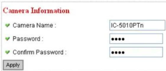
The descriptions of every setting in this menu will be given below:
| Item | Description |
| Camera Name | Please specify the name of this IP Camera here. This can be used to identify your camera on the network when you have more than one IP camera in the same network.Default name begins with ‘IC-‘ plus the last 6 characters of the MAC address of this IP camera. You can modify the name to the one you can remember and meaningful to you, but never give all IP cameras in the same network with same name. |
| Password | Please specify user name ‘admin’ ‘s password here. (The one you need when you log onto web management interface and use ‘admin’ as user name. |
| Confirm Password | Please input the same password again, to make sure there’s no typo. |
Click 'Apply' to save settings and make the new settings take effect.
2.6.2 Date / Time Setting
This setting allows you to change the date and time of the real time clock in this IP camera. You can set the time manually, or use network time protocol (NTP) to set the time automatically.
Date / Time Setting
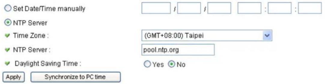
The descriptions of every setting in this menu will be given below:
| Item | Description |
| Set Date/Time manually / NTP Server | If you select ‘Set Date/Time manually’, you can set the date and time of this camera manually. Please input the date and time you wish to set here.Date / time format is YYYY / MM / DD HH:MM:SS Time is in 24-hour format.You can click ‘Synchronize to PC time’ to use the time of the computer you’re using.Example: 24^th August 2007 = 2007/ 08 / 24,and PM 9:24:30 = 21:24:30If you select ‘NTP Server’, the camera will get the date and time from NTP Server automatically. |
| Time Zone | Please select the time zone of the country / city of resident from dropdown menu here. |
| NTP Server | Please input the IP address or host name of NTP server here. You can use default value ‘pool.ntp.org’, or ask your ISP for the IP address or host name, if they have one. |
| Daylight Saving | If your area of residence uses daylight saving, select |
| Time | ‘Yes’; otherwise select ‘No’. |
| Synchronize to PC time | Click to input current time of your computer to ‘Set Date / Time manually’ field. |
Click ‘Apply’ to save settings and make the new settings take effect.
If you wish to use the date and time setting of the computer which is connecting to the camera, click 'Synchronize to PC time' button. The date and time setting of the computer will be filled to date and time setting in this page.
2.6.3 Schedule
You can use this menu to setup Schedule Snapshot/Recording settings:
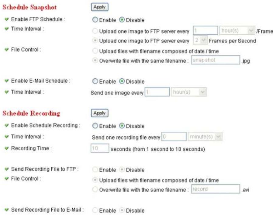
| Item | Description |
| Enable FTP Schedule | Select ‘Enable’ to send the Schedule Snapshot to the appointed FTP server, or select ‘Disable’ to disable this function. You have to configure FTP server parameters in ‘FTP Configuration’ menu first, so this function will take effect. |
| Time Interval | You can choose to upload one image to FTP server according to the time interval you wish, or choose to upload image as you wish to FTP server every second. |
| File Control | This option allows you to choose to upload each schedule snapshot with different file name composed of date/time, or to choose to upload the schedule snapshot with the same file name you wish. If you choose the latter, the prior-saved schedule snapshot will be overwritten by the latest schedule snapshot. |
| Enable E-Mail Schedule | Select ‘Enable’ to send the Schedule Snapshot to the appointed e-mail address, or select‘ Disable’ to disablethis function. You have to configure e-mail settings in ‘Email’ menu first, so this function will take effect. |
| Time Interval | This option allows the IP camera to send one image according to the time interval you wish. |
| Enable Schedule Recording | Select ‘Enable’ to enable schedule recording, or select ‘Disable’ to disable this function. |
| Time Interval | This option allows the IP camera to send one recording file according to the time interval you wish. |
| Recording Time | This option allows you to adjust the recoding time based on your preference.Note:The available recording time is based on the video resolution and video frame rate settings in ‘Video’ menu. |
| Send Recording File to FTP | Select ‘Enable’ to send the recoded video to the appointed FTP server, or select‘ Disable’ to disable this function. You have to configure FTP server parameters in ‘email & FTP’ menu first, so this function will take effect. |
| File Control | This option allows you to choose to upload each recorded video with different file name composed of date/time, or to choose to upload the recorded video with the same file name you wish. If you choose the latter, the prior-saved recorded video will be overwritten by the latest recorded video. |
| Send Recording File to E-Mail | Select ‘Enable’ to send the recorded video to the appointed e-mail address, or select‘ Disable’ to disable this function. You have to configure e-mail settings in ‘email & FTP’ menu first, so this function will take effect. |
2.6.4 Utilities
This menu allows you to upgrade firmware, clear all settings, reboot the IP camera, and switch LED lights on/off.
Utilities
√ Upgrade Firmware :
√ Reset To Factory Defaults :
Reboot Device :
LED Setting :
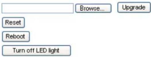
The descriptions of every setting in this menu will be given below:
| Item | Description |
| Upgrade Firmware | If you downloaded latest firmware file from our website, you can click 'Browse' button to pick a firmware file located on your computer's hard drive and you can upload the firmware file to the IP camera later.After you selected a proper firmware file from your computer, click 'Upgrade Firmware' button to start upgrade. DO NOT DISCONNECT NOW!If the firmware file you provided is invalid of you didn't provide the firmware file, you'll be prompted to select another valid firmware file again.The IP camera will reboot after the upgrade procedure is done. PLEASE NOTE THAT THE IP ADDRESS OF THE CAMERA WILL RESET TO DEFAULT VALUE: 192.168.2.3 |
| Reset to Factory Defaults | Clear all settings in the camera. Please think again before you do this, and then click this button to reset all settings.NOTE: IP address will be reset to default value '192.168.2.3' also. You'll need to change the IP addresssetting of your computer if the IP address of your computer does not begin with ‘192.168.2’, and subnet mask is not ‘255.255.255.0’, or you’ll not be able to connect to this IP camera again. |
| Reboot Device | If you found the IP camera is responding slowly or behaves strange, you can click this button to try to reboot the IP camera, this may help. |
| LED Setting | Click ‘Turn off LED light’ button to switch the LED light of this IP camera off, so all LEDs on the IP camera will stop working, in case you don’t want other people know the camera is transferring data.You can click this button again to switch LED lights on again. |
Click 'Apply' to save settings and make the new settings take effect.
2.6.5 Status
This menu provides all information about this IP camera, like firmware version, system uptime, date / time, and network information.
System
√ Firmware Version : v1.4 (Dec 31 2009 14:46:39)
√ Device Uptime : 12 hours 24 min 27 sec
System Time : 2009/01/01 20:24:12
LAN
IP Address: 192.168.3.3
Subnet Mask: 255.255.255.0
Gateway:
DNS Server : 168.95.1.1
√ MAC Address : 00:01:55:A3:12:01
HTTP Port: 80
PPPoE
√ Link Status : Disconnected
IP Address :
Subnet Mask:
Gateway:
DNS Server:
2.6.6 System Log
All activities of this IP camera will be logged, and you are allowed to enter 'System Log' menu to view these logs.
System Log
1970/01/01 00:00:13 Failed to open PT device!
1970/01/01 00:00:13 System startup [ v1.0 (May 4 2010 18:09:39) ]
2010/01/01 00:00:00 Start Storage Manager.. (PID:67)
2010/01/01 00:00:00 No storage medium found.
2010/01/01 00:00:00 Start Samba Storage Manager.. (PID:68)
2010/01/01 00:00:00 Set microphone volume to 80
2010/01/01 00:00:00 Set Line-Out volume to 80
2010/01/01 08:00:00 embedded av stream server started PID:72

2010/01/01 08:00:00 Failed to open PT device!
2010/01/01 08:00:00 Starting mpeg4 pipe server for Spook
2010/01/01 08:00:00 Starting h264 pipe server for Spook
2010/01/01 08:00:00 Starting audio pipe server for Spook
2010/01/01 08:00:00 embedded av stream controller started (PID:81)
2010/01/01 08:00:00 Opened /dev/pl_grab successfully
2010/01/01 08:00:01 Opened /dev/pl_enc successfully (MPEG4)
2010/01/01 08:00:01 Opened /dev/pl_enc successfully (MJPEG)
2010/01/01 08:00:01 Opened /dev/pl_264 successfully (H264)
2010/01/01 08:00:01 Opened /dev/pl_enc successfully (MD)
2010/01/01 08:00:01 Accepted a new connection from spook... (mpeg4 video)
2010/01/01 08:00:01 Accepted a new connection from spook... (h264 video)
2010/01/01 08:00:01 Accepted a new connection from spook... (audio)
2010/01/01 08:00:04 Schedule AVI system started (PID:62)
2010/01/01 08:00:04 E-mail schedule system started (PID:61)
2010/01/01 08:00:04 FTP schedule system started (PID:60)
2.7 Account
If you wish to allow other people to view the live image captured by this camera, but don't want to allow them to modify system settings, you can give them user-level user name and password, so they can only view the image and can not change any system setting.
This camera supports up to 16 users.

After you selected 'Account', you'll be prompted to input user account information:
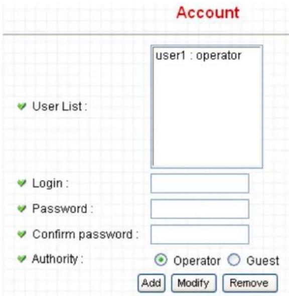
The descriptions of every setting in this menu will be given below:
| Item | Description |
| User List | Lists all users currently available. |
| Login | Input the login name (user name) of this account. |
| Password | Input the password of this user here. |
| Confirm password | Input the password of this user here again for confirmation. |
| Authority | Select the privilege of this user: Operator (able to enter camera & video menu) or Guest (view images only, but Guest account still needs to input User name/Passwordwhen accessing the camera). |
| Add | Click this button to add the account. |
| Modify | Modify an existing user's information. You have to select a user from user list first. |
| Remove | Remove an existing user. You have to select a user from user list first. |
Click ‘Apply’ to save settings and make the new settings take effect.
Please note: only one user (including administrator) will be able to view the image of IP camera at the same time.
If you wish to allow other people to view the live image captured by this IP camera without typing User name/Password, you can enable “Anonymous Login” in Anonymous page.
2.7 SDHC
...

After you selected 'System Info.', a sub-menu will appear. There are 4 sub-menus available here:
Status
Space Alarm
File Management
Please click the SD card setting you wish to set, then refer to instructions given below:
2.7.1 Status
Here shows the remaining card space for you.
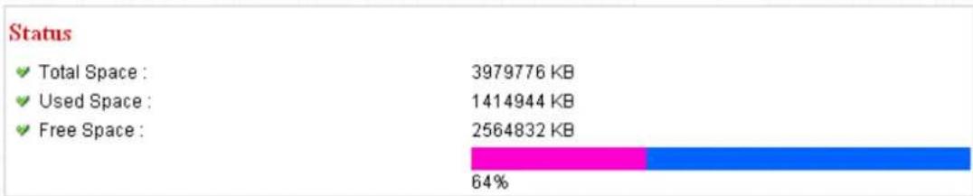
bar_stacked
| Status | Value (KB) | | :--- | :--- | | Total Space | 3979776 | | Used Space | 1414944 | | Free Space | 2564832 | | Segment Color | Pink | | Blue Segment | Blue | | Percentage (%) | 64% |2.7.2 Space Alarm
When you're using SD card to store captured image and video clip, you can have this camera to send an E-mail to you when there's only little remaining space left on SD card.
Space Alarm
√ Recipient E-Mail Address :
E-Mail Subject :
SMPT Server :
Sender E-Mail Address :
SMTP Port:
SMTP enable SSLv2V3 function :
SMPT Authentication :
User Name :
√ Password :
Reserved Space :
![[SD Card Space Alarm] 25 Enable Disable Enable Disable 30 MB Apply Send a test email Copy M](/content/2026/05/1017859/images/60151b94d66b20e562dfae8fe7ca5879508ca17554c6ce691dd06e0c278b3aac.jpg)
Please note: If you have set E-mail settings in 'Motion Picture' function, you can click 'Copy Mail Config' button to use the same setting. However, you can use a different setting here.
The descriptions of every setting in this menu will be given below:
| Item | Description |
| Recipient E-Mail Address | Input the E-mail address you wish to receive space alarm. |
| E-Mail Subject | Input the title of space alarm E-mail. |
| SMTP Server | Input the SMTP server address you wish to use to send E-mail. |
| Sender E-Mail Address | Input the sender E-mail address of the space alarm E-mail. |
| SMTP Port | You can set port number according to your mail server. |
| SMTP enable SSLv2/v3 function | Select ‘Enable’ if your SMTP server supports SSLv2/v3 such as gmail. |
| SMTPAuthentication | Select ‘Enable’ if the SMTP server you’re using requires authentication, and input the username and password below; If the SMTP server you’re using does not require authentication, select ‘Disable’ here. If you’re not sure, ask your ISP or network administrator. |
| User Name | Type the user name of the user who has the mail account. This setting is necessary when the SMTP server which sends e-mails performs authentication. |
| Password | Type the password of the user who has the mail account. This setting is necessary when the SMTP server which sends e-mails performs authentication. |
| Reserved Space | Select the amount of SD card space which will be reserved and will not be used from dropdown menu. |
Click ‘Apply’ to save settings and make the new settings take effect.
You can click 'Send a test email' button to send a test E-Mail by the configuration you set here.
2.7.3 File Management
You can use this menu to manage the files stored on SD card.
File Management
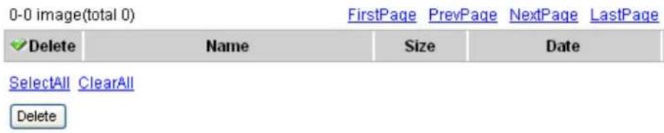
The descriptions of every setting in this menu will be given below:
| Item | Description |
| FirstPage | Jump to first page of file list. |
| PrevPage | Jump to previous page of file list. |
| NextPage | Jump to next page of file list. |
| LastPage | Jump to last page of file list. |
| SelectAll | Select all files in this page. |
| ClearAll | Clear all files in this page. |
| Delete | Delete selected files. |
Chapter III: Using Surveillance Software
3-1 Installing IP Camera Surveillance Software
The IP camera surveillance software provides various functions like video recording, after this software is installed, you can use your IP camera to safeguard your property. Please follow the following instructions to install the surveillance software.
- Click "16 channel viewer" in supplied CD-ROM, when the following window appears, click 'Next'.
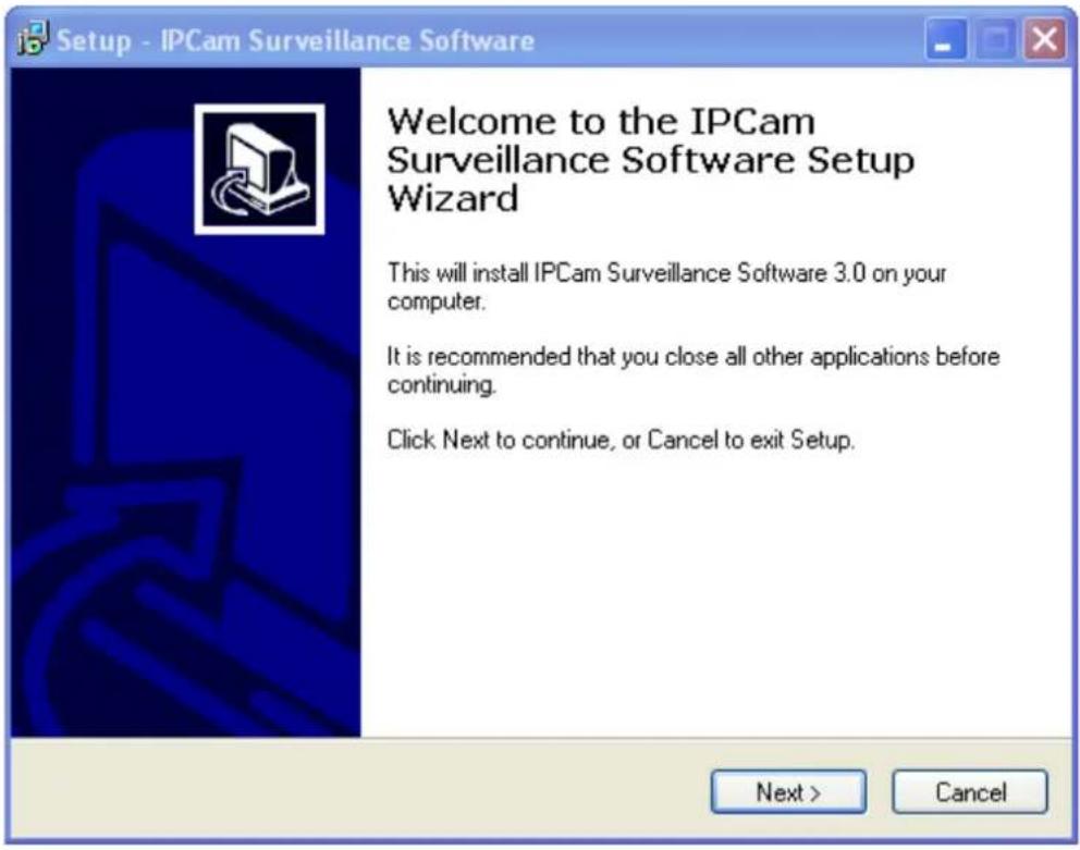
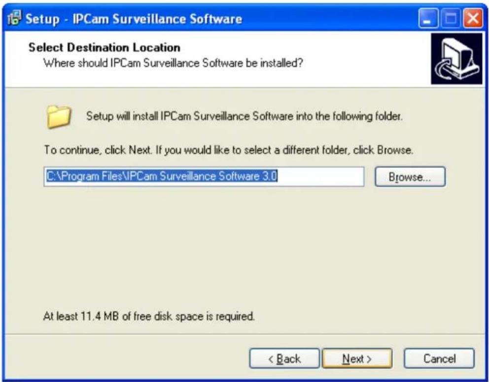
- You can specify the destination folder of software installation, you can just use the default folder, and click 'Next' to continue.
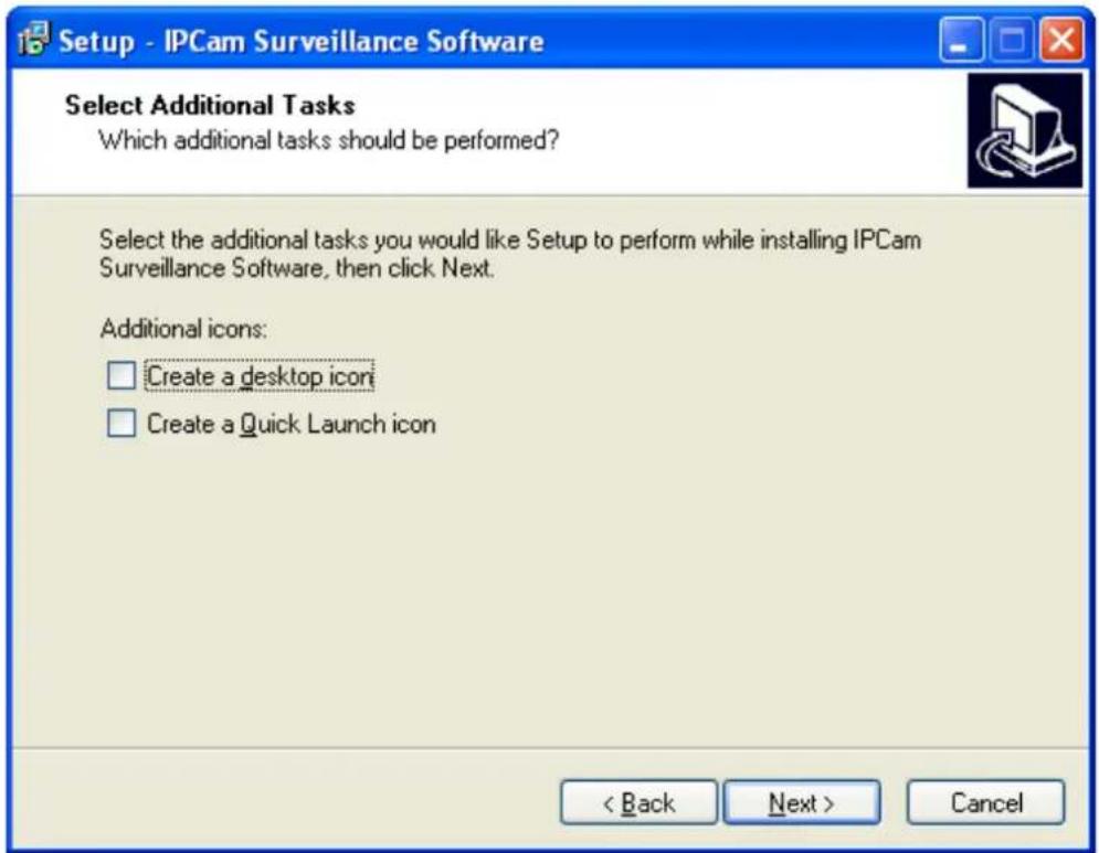
- If you need installation program to create a desktop icon or a quick launch icon for you, click all items you need here, than click 'Next' to continue.
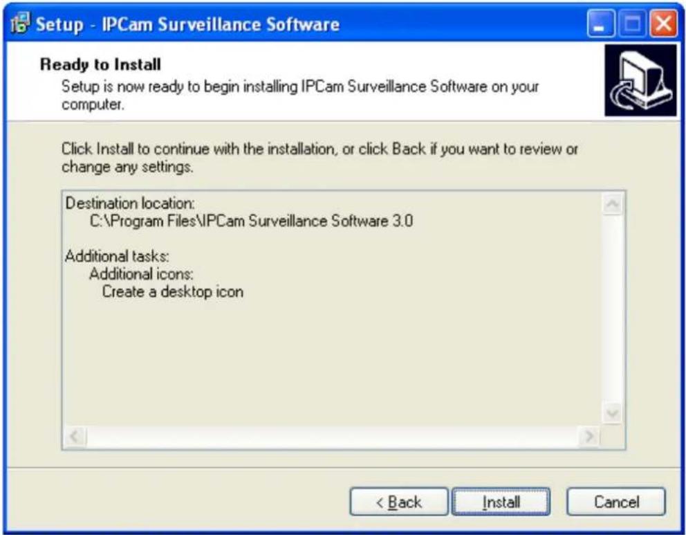
- Here lists all options you chose in previous steps, if everything's correct, click 'Install' to start installing procedure, or click 'Back' to go back to previous step to modify installing settings.
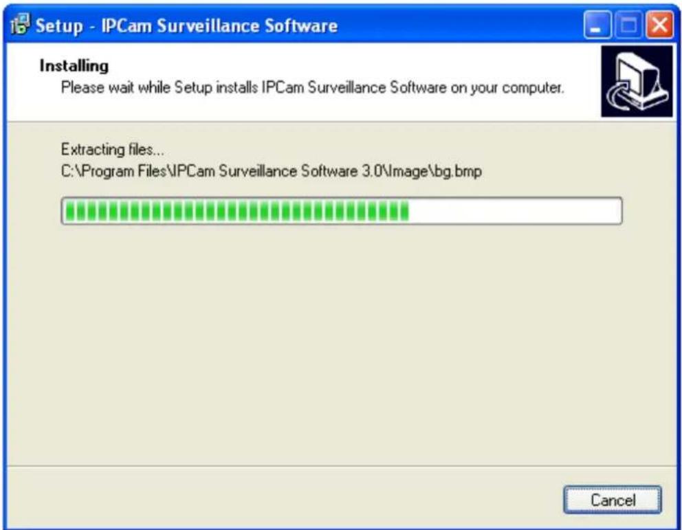
- The installing procedure will take some time, please be patient.
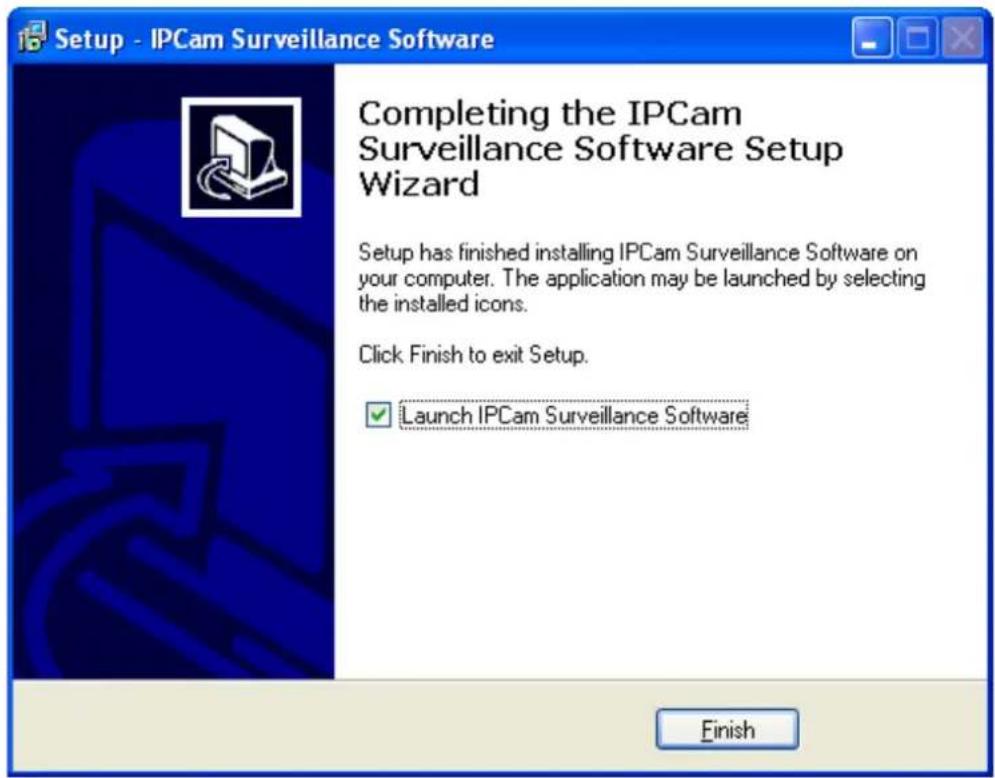
- When you see this window, it means the software installing procedure is complete. Please click 'Finish' to finish the procedure (IP camera surveillance software will start after you click 'Finish' button, if you want to start it later, uncheck 'Launch IPCam Surveillance Software' box).
3-2 Using IP camera surveillance software
You can click 'IPCam Surveillance Software' icon from desktop, quick launch bar, or start menu to start the IP camera surveillance software.
Before you start:
IP camera surveillance software will only work when your monitor's resolution is '1024 x 768'. Please change the resolution before you use IP camera surveillance software, or it won't start.
Here are descriptions for all components of IP camera surveillance software:
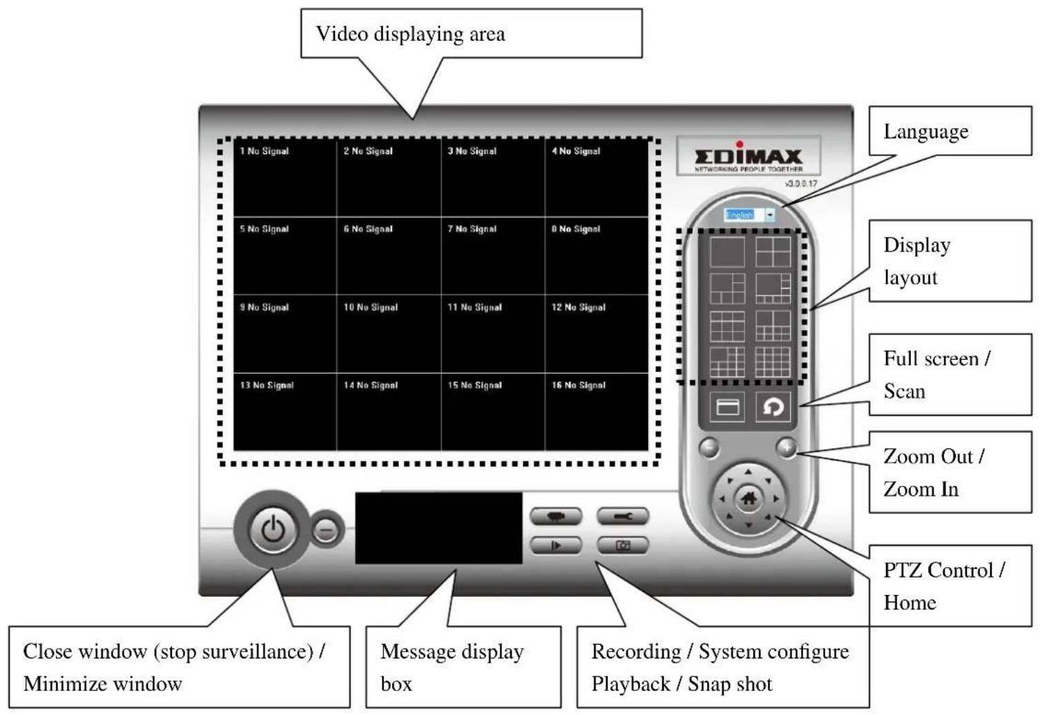
You can put the mouse cursor on a certain component and see its button name, and here're detailed descriptions of all buttons:
| Item | Description |
| Video displaying area | The image of all connected cameras will be displayed here. |
| Language | Select a language from this dropdown menu to change display language. |
Display layout | Change camera image display layout (Click a layout icon to change camera display layout). There are 8 kinds of available display layouts. |
Full screen | Click this button to switch to full screen mode (only display all camera's image), press 'ESC' key to quit full screen mode. |
Scan | Click this button and the IP camera surveillance software will switch displaying the image of all connected camera automatically. Click this button once to activate scan function (scan icon will become blue ), click again to stop scanning (scan icon will become white ) |
Zoom out | Zoom-out (To see more objects).This function is only available for supported cameras. |
Zoom In | Zoom-in (Too see more details).This function is only available for supported cameras. |
PTZ control | There are 8 directions in PTZ control ring. If the camera you connect support PTZ, you can use PTZ control ring to change the direction that camera points to.This function is only available for supported cameras. |
Home | Click this button to return the camera to 'Home' (default) position.This function is only available for supported cameras. |
Recording | Start video recording. |
Configure | Software / camera configuration. |
Playback | Playback a recorded video file. |
Snapshot | Take a snapshot of current camera. |
| Message display | Displays all system messages like camera is disconnected etc. |
Close window (stop surveillance) | Terminates IP camera surveillance software. |
Minimize window | Minimizes IP camera surveillance software window. |
| Video displaying area | Displays the image of all cameras by the display layout you selected. |
3-3 Configure IP camera surveillance software
3-3-1 Configure cameras
Before you use this IP camera surveillance software, you must configure the camera(s) you wish to connect. Please click 'System configure' button and a popup menu will appear:
Configure Cameras
General Options
Please select 'Configure Cameras' to configure cameras:
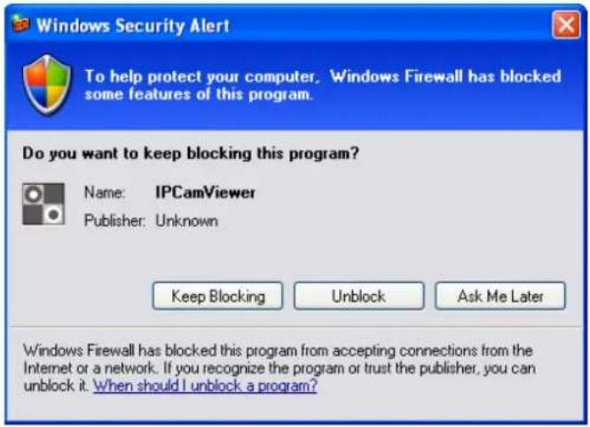
Note: If you're prompted by a windows security alert which asks you if you want to block 'IPCamViewer' program, please click 'Unblock' button, of IP camera surveillance software will not be able to function correctly.
3-3-1-1 'Camera' tab
In this tab you can configure all cameras you wish to connect. Up to 16 cameras can be connected simultaneously:
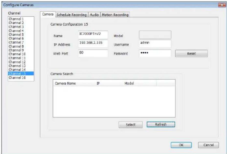
Here are the descriptions of all setting items:
| Item | Description |
| Channel | Select the channel number you wish to set. |
| Camera Search | All cameras found on your local network will be displayed in ‘Camera Search’ box. |
| Select | Select a camera listed in ‘Camera Search’ box, and click ‘Select’ button to fill all parameters of selected camera in every camera configuration fields. |
| Refresh | Rescan all cameras on your local network. If you didn’t see the camera you expected in ‘Camera Search’ box, or new cameras has been joined to your local network after last scan. |
| Name* | Input the name of camera here. Default value is the first 6 bytes of camera’s MAC address, you can change the name of camera so you can remember the camera’s location of purpose easily. |
| Model | Displays the model of selected camera, this field can not be changed. |
| IP* | Input the IP address of camera. |
| Username* | Input the user name of camera. |
| Web Port* | Input the web port of the camera. By default it's ‘80’. |
| Password | Input the password of camera. Default value is ‘1234’. You should change the password if you changed the password of selected camera. |
| Video Format** | Select the video encoding format of this camera (MJPEG or MPEG4). |
| Reset | Clear all fields in ‘Camera Configuration’ section. |
| OK | Save settings in this tab. |
| Cancel | Discard all settings in this tab. |
*: It's recommended to use 'Select' button to fill the content of this field.
**: Only available for cameras support this function.
After you've set all channels you wish to set, click 'OK' to save settings, and if everything's correct, you'll see the camera's image in IP camera surveillance software's main menu:
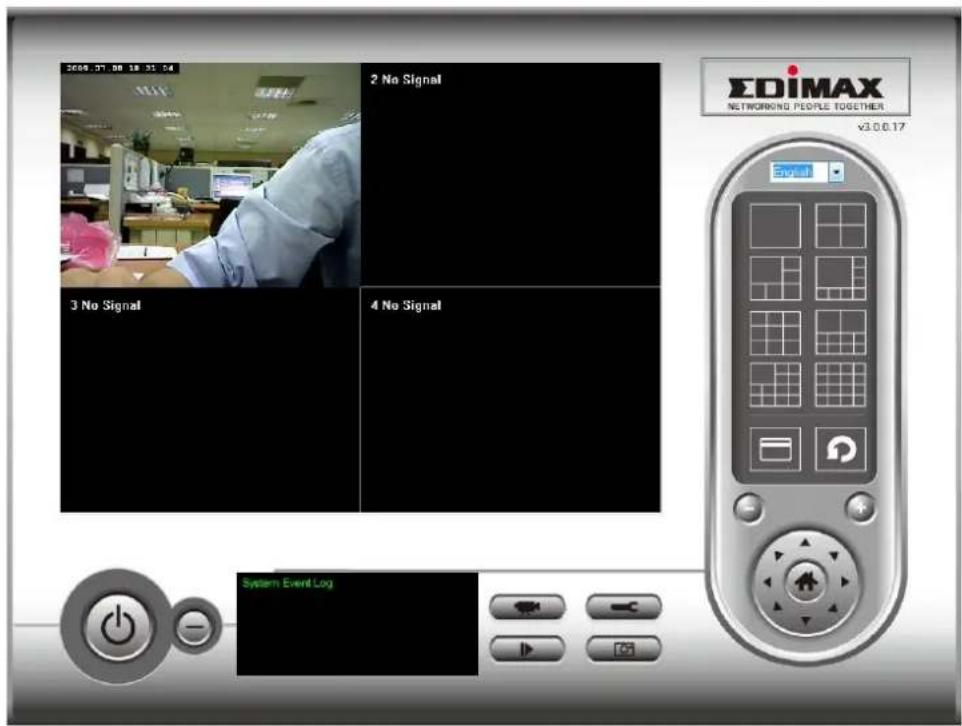
3-3-1-2 Schedule Recording
In this tab, you can setup scheduled video recording, so you can record the video captured by all cameras you have by a pre-defined schedule.
![Configure Cameras Channel Channel 1 Channel 2 Channel 3 Channel 4 Channel 5 Channel 6 Channel 7 Channel 8 Channel 9 Channel 10 Channel 11 Channel 12 Channel 13 Channel 14 Channel 15 Channel 16 Camera Schedule Recording Audio Motion Recording One Time Schedules 2009/07/10 11:03:27 - 2009/7/10 11:10:27 New Edit Delete Weekly Schedules [ Sun Mon Tue Wed Thu Fri Sat ] 00:00:00 - 23:59:59 New Edit Delete OK Cancel](/content/2026/05/1017859/images/273c281f0acdfafbbf013d7814211713ab52b6de8f341a03ff2f8f0fb17e238d.jpg)
Here are the descriptions of all setting items:
| Item | Description |
| Channel | Select the channel number you wish to set. |
| One Time Schedules | You can specify the one-time schedule for selected camera; this schedule will be executed once only. |
| New (One Time Schedules) | Click this button and a new window will appear: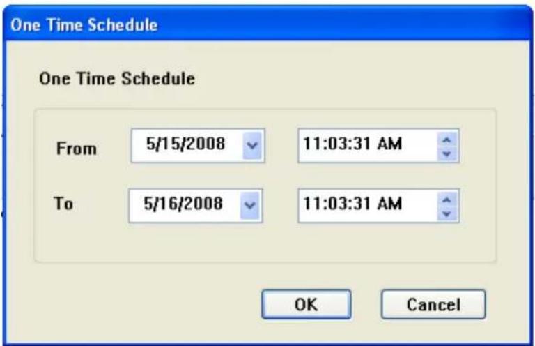 Please specify the time duration of this one-time schedule (the date and time of ‘From’ and ‘To’), then click ‘OK’ to save settings.Please note you must set a schedule that will be happened in the future, you can not set a schedule in the past. Please specify the time duration of this one-time schedule (the date and time of ‘From’ and ‘To’), then click ‘OK’ to save settings.Please note you must set a schedule that will be happened in the future, you can not set a schedule in the past. |
| Edit | You can modify a scheduled recording item. Select a schedule in ‘One Time Schedules’ list, and click ‘Edit’ button to edit the start and end time of this schedule. |
| Delete | Delete a selected schedule item. |
| New(Weekly Schedules) | Click this button and a new window will appear: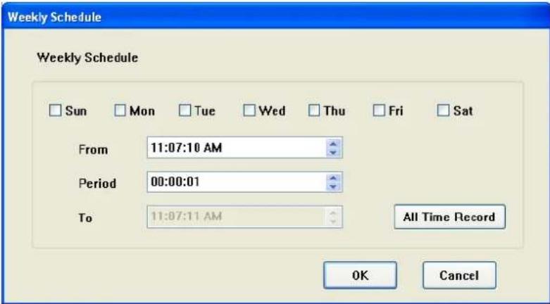 You can define recording schedule that will be executed at the specified time of certain weekday(s) in a week.Please check all weekdays that applies, and set the start time in ‘From’ field. You can set the duration of video recording in ‘Period’ field (format is HH:MM:SS), and the end time will be calculated automatically and displayed in ‘To’ field. You can also click ‘All Time Record’ button to define a recording schedule that will be executed every weekday, from 12:00:00AM to 11:59:59PM.Click ‘OK’ to save changes. You can define recording schedule that will be executed at the specified time of certain weekday(s) in a week.Please check all weekdays that applies, and set the start time in ‘From’ field. You can set the duration of video recording in ‘Period’ field (format is HH:MM:SS), and the end time will be calculated automatically and displayed in ‘To’ field. You can also click ‘All Time Record’ button to define a recording schedule that will be executed every weekday, from 12:00:00AM to 11:59:59PM.Click ‘OK’ to save changes. |
| Edit | You can modify a scheduled recording item. Select a schedule in ‘One Time Schedules’ list, and click ‘Edit’ button to edit the start and end time of this schedule. |
| Delete | Delete a selected schedule item. |
| OK | Save settings in this tab. |
| Cancel | Discard all settings in this tab. |
3-3-1-3 Audio
For cameras that support audio, you can use this tab to decide if you wish to hear the audio captured by selected camera.
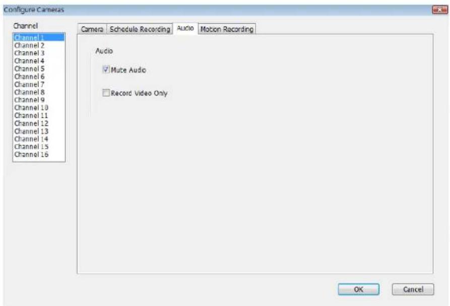
Here are the descriptions of all setting items:
| Item | Description |
| Channel | Select the channel number you wish to set. |
| Mute Audio | Check this box and the IP camera surveillance software will not play the audio captured by this camera. |
| Record Video Only | Check this box and the IP camera surveillance software will not record the audio captured by this camera. |
| OK | Save settings in this tab. |
| Cancel | Discard all settings in this tab. |
3-3-1-4 Motion Record
With this function activated, only motions captured by the camera will be recorded, so you don't have to waste hard disk storage space on images you don't need to pay attention to.
WARNING: For applications that security is highly concerned, it's not recommended to use this function since some tiny changes you may need to know may not be able to trigger the camera and the camera will not start recording.
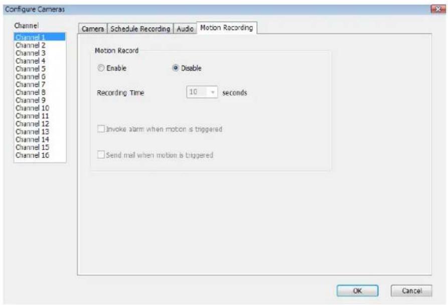
Here are the descriptions of all setting items:
| Item | Description |
| Channel | Select the channel number you wish to set. |
| Enable | Enable motion record function. |
| Disable | Disable motion record function. |
| Recording Time | Select the time duration that camera will record when a motion has been detected from dropdown menu in seconds. |
| Invoke alarm when motion is triggered | Send an alarm when a motion has been detected by the camera. |
| Send mail when | Send an email to a pre-defined address when a motion |
| motion is triggered | has been detected by the camera. |
| OK | Save settings in this tab. |
| Cancel | Discard all settings in this tab. |
3-3-2 General Settings
You can set system-wide settings of this IP camera surveillance software in this menu.
3-3-2-1 'General' tab
All general settings like file storage directory and recording spaces can be set here.
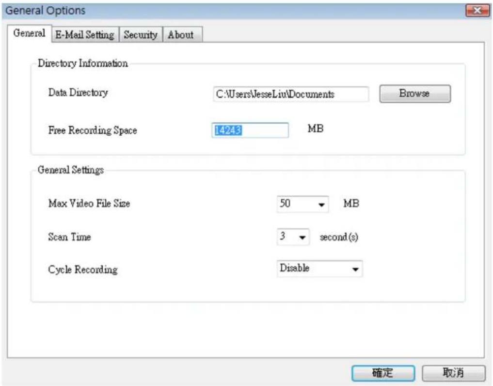
Here are the descriptions of all setting items:
| Item | Description |
| Data Directory | Set the directory (folder) you wish to store the recorded video and captured image. You can click ‘Browse’ button to pick a directory in your hard disk. |
| Free Recording Space | Displays remaining storage space. |
| Max Video File Size | Defines the maximum file size of every video file. When the size of file exceeds this value, IP camera surveillance software will open another file to record the video. |
| Scan Time | Define the time period to pause between every camera switch when you activate ‘Scan’ function. |
| Cycle Recording | You can decide the behavior when hard disk space is full:Disable: Do not overwrite recorded video files.Enable: Overwrite recorded video files. |
| OK | Save settings in this tab. |
| Cancel | Discard all settings in this tab. |
3-3-2-2 'E-Mail Setting' tab
If you want to use motion detection function and wish to get an email that contains the image captured by the camera, please setup your email related parameters here first.
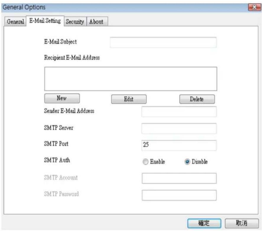
Here are the descriptions of all setting items:
| Item | Description |
| E-Mail Subject | Specify the subject of sending email. |
| Recipient E-Mail Address | Here lists all email addresses you set. |
| New | Click this button and you’ll be prompted to input the email address. Click ‘OK’ to save changes. |
 | |
| Edit | Select an email address from ‘Recipient E-Mail Address’ box, and click ‘Edit’ to edit the email address. |
| Delete | Delete selected email address. |
| Sender E-Mail Address | Specify the email address of email sender. |
| SMTP Server | Specify the IP address or host name of the SMTP server you wish to use. For most of ISPs they will only allow its subscriber to use their SMTP server, if you don’t know which SMTP server you should use, please refer to the setting of your email software or ask your ISP / network administrator. |
| SMTP port | Specify the port number of the SMTP server you wish to use here. By default (and the setting of most of SMTP servers) it’s ‘25’. |
| SMTP Auth | Select ‘Enable’ if your SMTP server requires authentication, select ‘Disable’ if it’s not required. If you don’t know if your SMTP server requires authentication, please refer to the setting of your email software or ask your ISP / network administrator. |
| SMTP Account | Input the SMTP account (username) of your SMTP server here. In most cases, it’s the same with your POP3 username (the one you used to receive email). Please refer to the setting of your email software or ask your ISP / network administrator if you’re not sure about this. |
| SMTP Password | Input the SMTP password of your SMTP server here. In most cases, it’s the same with your POP3 password (the one you used to receive email). Please refer to the setting of your email software or ask your ISP / network administrator if you’re not sure about this. |
| OK | Save settings in this tab. |
| Cancel | Discard all settings in this tab. |
3-3-2-3 Security
If you don't want other people to access this IP camera surveillance software, you can set a password to protect it.
You'll need to input the password every time you wish to use this IP camera surveillance software:
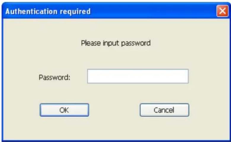
To set password, please use 'Security' tab in 'General Options' menu:
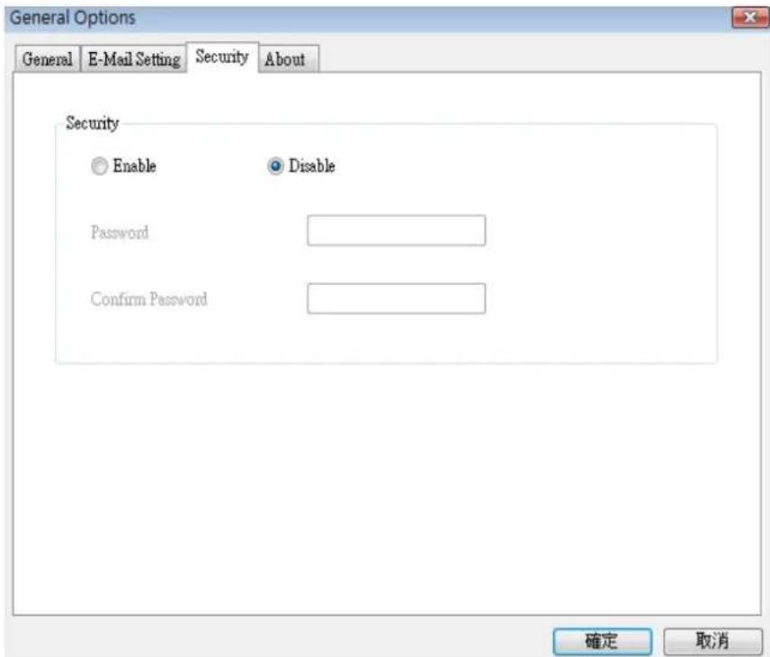
Here are the descriptions of all setting items:
| Item | Description |
| Enable | Requires password authentication when this software starts. |
| Disable | Password authentication is not required when this software starts. |
| Password | Input the password you wish to use here. |
| Confirm Password | Input the password you wish to use here again. |
3-3-2-4 About
This tab shows the version number of the IP camera surveillance software you're using.
3-4 Change Display Layout
This IP camera surveillance software provides 8 kinds of display layout:
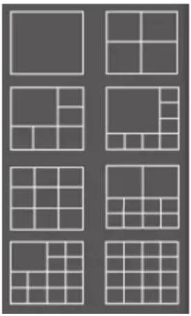
natural_image
Grid of nine identical gray squares arranged in 3x3 pattern, no text or symbols presentEvery layout displays different number of camera and camera arrangement, you can click the icon that presents a specific kind of layout, and the video displaying area will change accordingly.
Layout style 1: 1Camera only | Displays the video of 1 camera only. |
Layout style 2: 4Cameras | Displays the video of up to 4 cameras. |
Layout style 3: 6 Cameras | Displays the video of up to 6 cameras. |
Layout style 4: 8 Cameras | Displays the video of up to 8 cameras. |
Layout style 5: 9 Cameras | Displays the video of up to 9 cameras. |
Layout style 6: 10 Cameras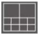 | Displays the video of up to 10 cameras. |
Layout style 7: 13 Cameras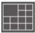 | Displays the video of up to 13 cameras. |
Layout style 8: 16 Cameras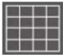 | Displays the video of up to 16 cameras. |
3-5 Full-screen mode
If you want to use all available spaces on your monitor to display surveillance image, you can click 'Full Screen' button to switch display mode to full-screen mode.
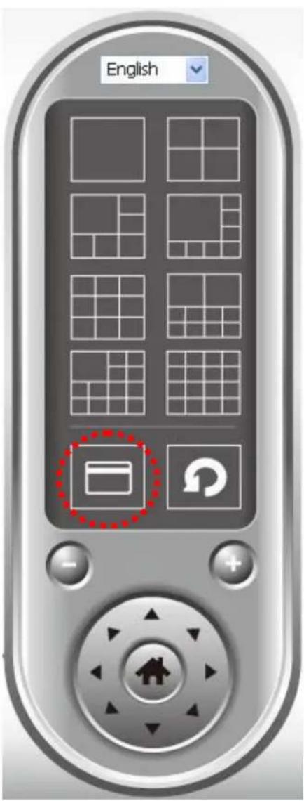
To exit full-screen mode, press 'ESC' key.
3-6 Scan
If you have more than one camera configured, and you wish to switch the displaying image between cameras, you can click 'Scan' button to switch between all configured cameras.
NOTE: If a camera is configured but disconnected, it will still be displayed in a scan sequence (you'll see nothing and you'll see 'Disconnected' text displayed at the upper-left corner of display image).
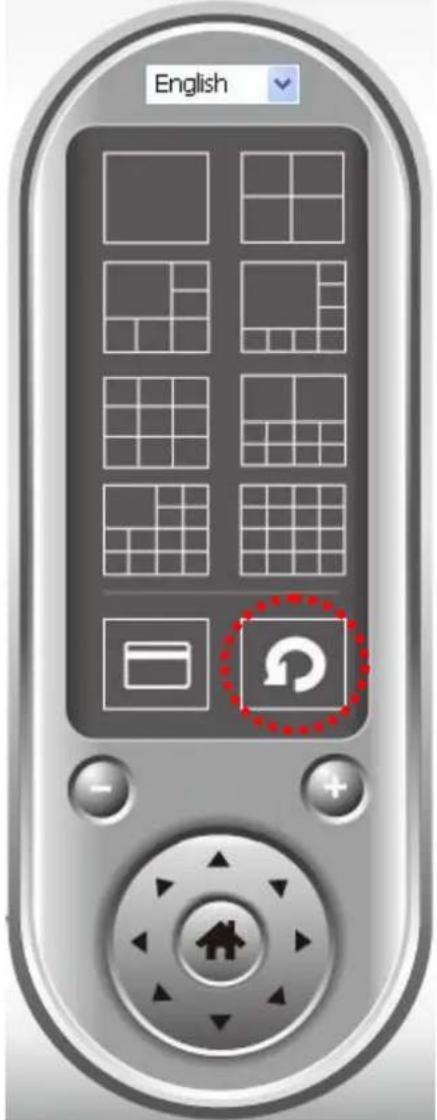
Click 'Scan' button once to activate scan function (scan icon will become blue), click again to stop scanning (scan icon will become white)
3-7 Zoom-in / Zoom-out
For cameras that support zoom-in / zoom-out function, you can use this function to see more objects that fall in the scope of camera's view, or enlarge the image size of a certain object to see its detail.
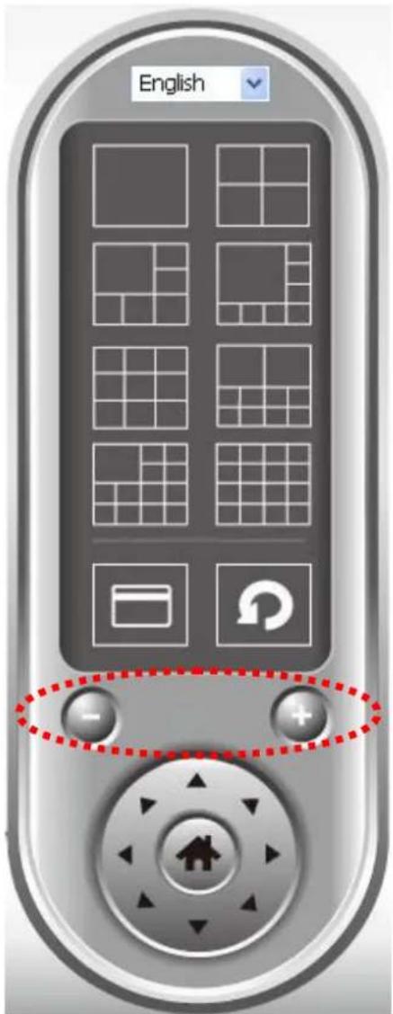
Please select a camera in video displaying area by clicking on its image, then click button to see more objects that fall in the scope of camera's view, or click to enlarge the image size of a certain object to see its detail (Before zoom-in, you may need to use PTZ buttons - described in next section) to find an object you wish to see its detail).
3-8 PTZ
For cameras that support pan - tilt function ( but this model doesn't support PTZ function), you can change the position that camera points to, to see different places that fall in the scope of camera's view.
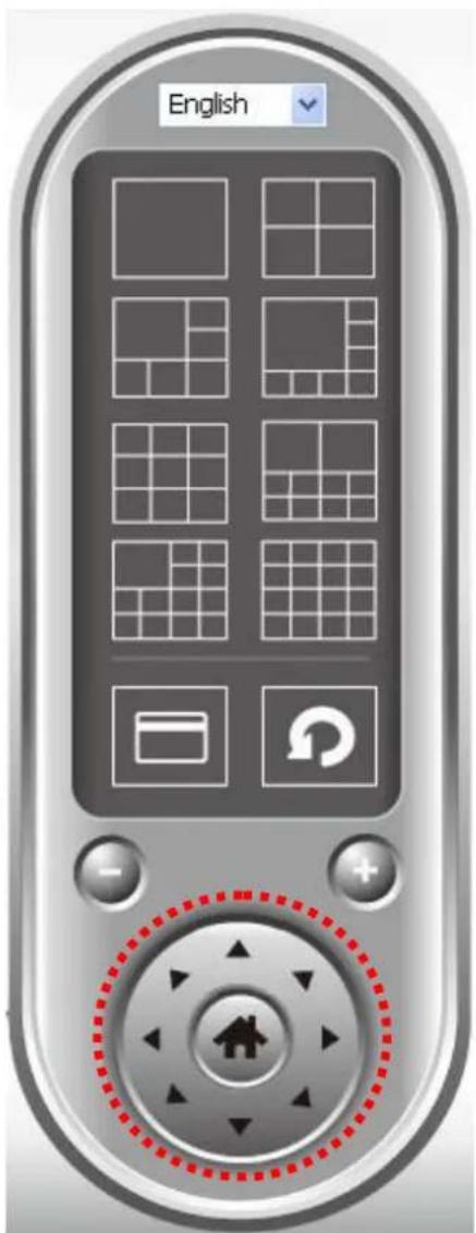
Please select a camera in video displaying area by clicking on its image, and then click the directions you wish the camera to move to (total 8 directions available). Click 'Home' button ( ) to return to camera's home (default) position.
3-9 Snapshot
You can take a snapshot of selected camera and save it to 'Snapshot' sub-folder of pre-defined data directory.
natural_image
User interface buttons including video camera, wrench, play button, and camera icon (no text or symbols)Click snapshot button once to take a snapshot; you can take as much snapshot as you want before hard disk is full.
3-10 Recording
You can start video recording of selected camera manually by clicking 'Start Recording' button:
natural_image
User interface buttons including video camera, wrench, play, and camera (no text or symbols)When recording starts, you'll see a message displayed in message displaying box like '1/1 10:00:00, Camera 2 Start Manual', which means camera 1 starts recording manually on 1/1 at 10:00:00.
To stop recording, click 'Start Recording' button again, and you'll see a message displayed in message displaying box like '1/1 10:00:00, Camera 2 Stop Manual'.
3-11 Video Playback
You can playback all recorded video by clicking this button.
natural_image
User interface buttons including video camera, wrench, play button, and camera (no text or symbols)A new window will appear:
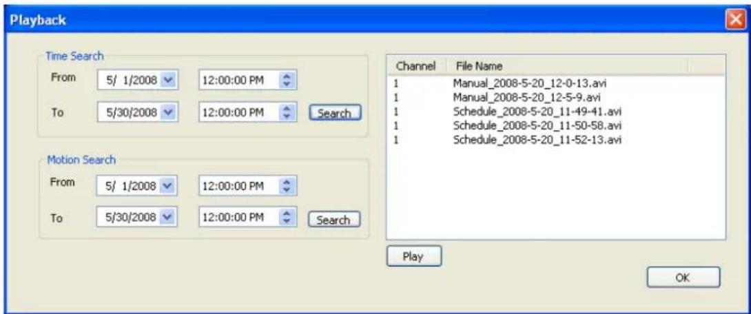
You have to search the video file before you can play it. There are two kinds of video search: Time Search (search all videos file that falls in a specific period of time) and Motion Search (search all videos recorded by motion detection function and falls in a specific period of time).
Please define the start and end date / time of the time period you wish to search, and then click 'Search' button (of 'Time Search' of 'Motion' Search'). All found videos will be displayed, select the video you wish to play and click 'Play' button to playback.
Chapter IV: How to View IP Camera over the Internet with iPhone
IC-7010 series features iPhone support for iPhone users to monitor their home using Edimax IP-Cameras.
Please check following instruction for installation. The following instruction applies to all Edimax routers
Step1:
Ensure My-PC is Internet-ready via Router
Step 2:
Check with your ISP (Internet Service Provider) whether a Public and fixed IP address is assigned to you. An IP address is like an unique phone number that is totally different from all the others' for calling a particular person. You could browse the Internet or monitor your home over the Internet with iPhone by using this unique IP address. Therefore, an unique IP address is a Public and fixed IP address. With this, it's much easy for iPhone monitoring your home. For example, an IP address looks like numbers separated with a dot as: 192.168.2.3
(1) Fixed and public IP address:
All IP addresses different from the following are fixed and public IP address
10.0.0.0 - 10.255.255.255
172.16.0.0 - 172.31.255.255
192.168.0.0 - 192.168.255.255
Write down this IP address and go to Step 3. In this guide, we use a hypothetical IP address, 61.61.61.1 (yours is different)
(2) Dynamic IP address
If your ISP service staff cannot tell you what IP address is for you, you can still monitor your home with iPhone, but it turns more complicated.
Your IP address for browsing Internet will change by hours or by days.
Over 90% chance, you may get a dynamic IP address. There is a solution called Dynamic DNS (DDNS) for free. With this, you could register a name like http://my-name.dyndns.org for example to find out Edimax IP camera in the I-Phone. To apply for this, refer to the Appendix "How to apply for a free
DNS account in the http://www.dyndns.org " In this guide, we assume you have already got http://my-name.dyndns.org. (yours may vary) and go to Step 3.
Step 3:
Configure the 1 ^st Camera based on the following:
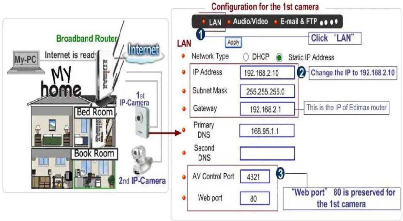
Configure the 2^nd Camera based on the following:
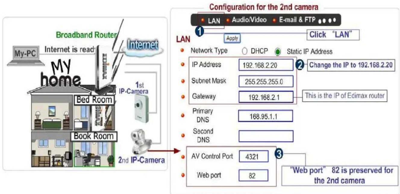
Configure the Broadband Router based on the following:
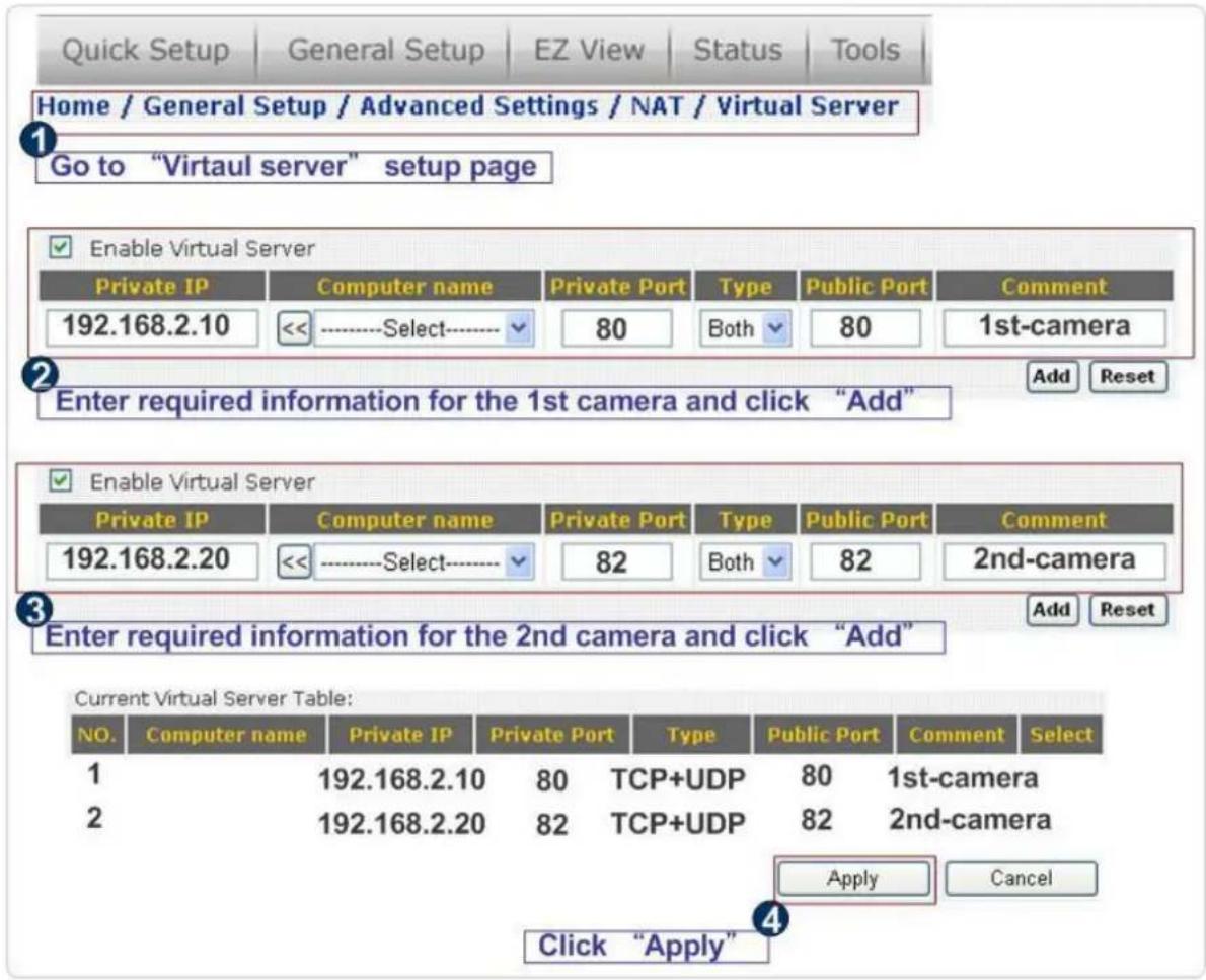
Step 4:
Configuration for iPhone.
(1) Make sure Internet connection is ok with iPhone and click "Safari"
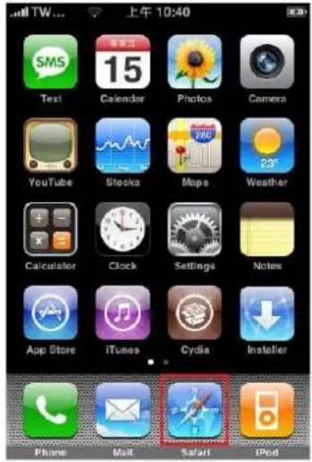
(2) Enter the IP address of your router's "fixed and public IP address" (check the Step 2 for details)
Note: "/ipcam.asp" is needed
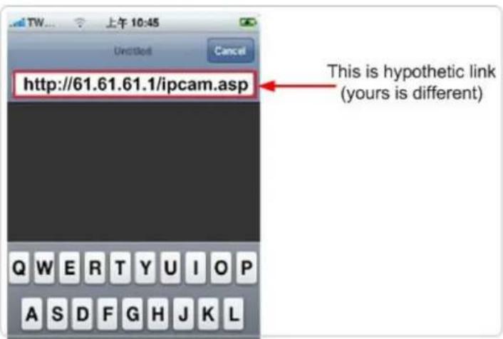
If no fixed and public IP address is given by your ISP, you may enter a link like http://my-name.dyndns.org/ipcam.asp (Again, this link is hypothetic)
You could have your own name like http://john.dyndns.org, mary.dyndns.org etc. To apply for a free account, refer to the Appendix “How to apply for a free DNS account in the http://www.dyndns.org “
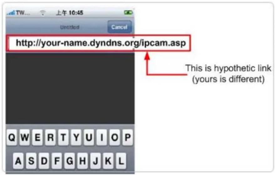
(3) Enter user name & password for the Edimax IP camera. By default, user name is admin and password is 1234
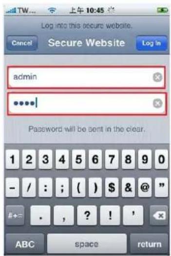
(4) Let's add the 1^st IP camera. Click first window and Setting.
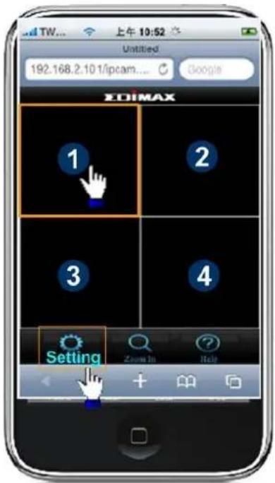
(5) Click "Add" when finishing the following configuration:
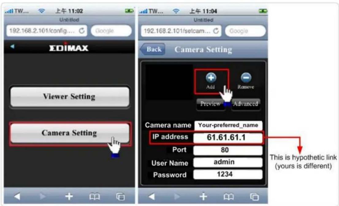
(6) Click "Add" when finishing the following configuration for the 2^nd IP camera
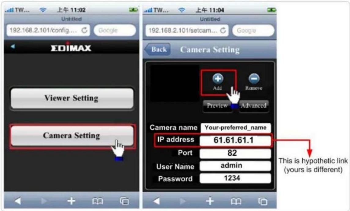
(7) Configuration is complete. You could see the live video of the 2^nd IP camera.
Chapter V: Appendix
5.1 Specification
Max Resolution: 1280 x 1024 pixels
Sensor: 1.3Mega pixels 1/4" color CMOS sensor
Gain control: Automatic
Exposure: Automatic
White Balance: Automatic
Image (Video Setting)
Image compression: MJPEG/MPEG4/H.264 Image Video
Digital 24-bit Color
Frame rate: 10-15fps@SXGA, XGA, 30fps@QVGA, 20fps@VGA
Video resolution: MJPG&H.264: 1280x1024, 640x480, 320x240
MPEG4: 1024x768, 640x480, 320x240
System Hardware
LAN Connector: One RJ-45 port to connect to 10/100Mbps Ethernet
Wireless: IEEE 802.11b/g/n (*Wireless Model Only)
LED Indicator: Power/Audio/LAN/WLAN for wired and wireless model
Power/Audio/ACT/LAN for POE model
HTTP/Utility
Includes easy-to-find and surveillance utility
Provides Web based Management
View multiple cameras simultaneously on PC surveillance software up to 16 cameras
at a time
Supports 16 additional user accounts for viewing camera
Auto sending Snap Shot or video by E-mail or FTP
Support DDNS and UPnP functions
Supports Windows 2000/XP/Vista/Win7
Firmware Upgradeable
EMI & Safety
FCC, CE class B
5.2 How to apply for a free DNS account in the http://www.dyndns.org
It's very likely your IP address (the Internet location) keeps changing every a couple of hours or every day depending on your ISP's policy. Therefore, as shown in the following figure, you may be assigned with an IP address, "61.61.61.1" hours ago, and now with a new IP address, "72.72.72.1". This means the router at "My-home" can be found at http://61.61.61.1 over the Internet is no longer available after a few hours. To find out the new location (IP address) of the router at My home over the Internet, you need to login to the router, checking the new IP address. However, this is not a workable solution.
To overcome this problem, an Internet service called DDNS is designed to help you trace the log of the changing IP address linking with a web site address (URL). As shown in the following figure, one PC called DDNS server keeps revising the record “your-name.dyndns.org vs 61.61.61.1” in its internal DNS directory. It ends up entering http://your-name.dyndns.org in the iPhone can find out the 2 IP camera at My-home.
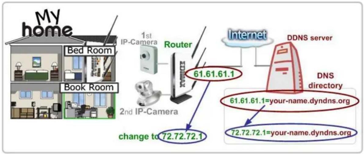
flowchart
graph TD
    A["My home"] --> B["Bed Room"]
    A --> C["Book Room"]
    B --> D["1st IP-Camera"]
    C --> E["2nd IP-Camera"]
    D --> F["Router"]
    E --> F
    F --> G["Internet"]
    G --> H["DDNS server"]
    H --> I["DNS directory"]
    I --> J["61.61.61.1=your-name.dyndns.org"]
    I --> K["72.72.72.1=your-name.dyndns.org"]
    L["change to 72.72.72.1"] --> M["2nd IP-Camera"]
    style A fill:#f9f,stroke:#333
    style B fill:#ccf,stroke:#333
    style C fill:#ccf,stroke:#333
    style D fill:#cfc,stroke:#333
    style E fill:#cfc,stroke:#333
    style F fill:#fcc,stroke:#333
    style G fill:#cff,stroke:#333
    style H fill:#ffc,stroke:#333
    style I fill:#ffc,stroke:#333
    style J fill:#cfc,stroke:#333
    style K fill:#cfc,stroke:#333
The following are steps to apply for an account named "your-name.dyndns.org" in the http://www.dyndn.org and how this account is configured into Edimax router.
Note: http://www.dyndn.org is not a branch or affiliate of Edimax. No commercial relation is involved between these 2 companies. The related service offered in the http://www.dyndns.org is for free for a specific time. However, Edimax does not guarantee this service.
First, go to http://www.dyndns.org and apply for an account.
And follow the steps:

Go to www.dyndn.org
Address

http://www.dyndns.org


Go

Click "Dynamic DNS"

Click "Manage Hosts"
Get Started
Manage Hosts

Click "Add New Host"
Host Services
↑ N
| Hostname | Service | Details | Last Updated |
Add New Host

Decide your preferred name. Click "Add to cart"
Hostname:
Your-name
Dyndns.org
Wildcard Status: Disabled [Want Wildcard support?]
Service Type:
Host with IP address [?]
○ WebHop Redirect [?]
○ Offline Hostname [?]
Add To Cart

Finished. The new DDNS record is traced
| Hostname | Service | Details | Last Updated |
| your-name.dyndns.org | Host | 61.61.61.1 | Apr. 06, 2010 10:35 PM |
Now, you could locate your home IP camera using
http://your-name.dyndns.org
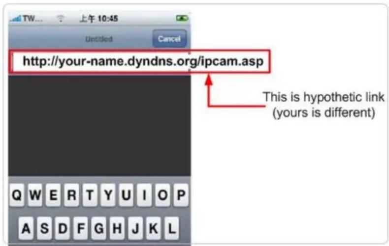
5.3 Troubleshooting
If the IP camera is not working properly, before you contact the dealer of purchase for help, please check the troubleshooting list here, this may help you to solve the problem by yourself and therefore saves your valuable time.
| Scenario | Possible Solution |
| I can not connect to IP camera | a. Please confirm the IP address setting of the computer you’re using. If they’re not in the same subnet, they will not be able to communicate with each other.b. Please make the IP address you used to connect to the IP camera is correct.c. If you forget the IP address of the IP camera, you will have to reset it to factory default value (which is 192.168.2.3) by pressing ‘reset’ button at the bottom of the IP camera. You’ll need a pen or pin to be able to press the reset button. Press and hold reset button for 5 seconds, then try to connect to the IP camera with IP address ‘192.168.2.3’ again.d. Please make sure IP camera is correctly powered (the ‘Power’ LED should be on).e. If you’re trying to connect to the IP camera from Internet, please make sure the port that IP camera uses (Video and HTTP port, see section 2.3.1) is not blocked by firewall or other software / hardware.f. Contact dealer of purchase for help, if above solutions do not work. |
| Image refreshes very slow | a. Try a higher frame rate setting, if it’s not 30.b. Try a lower resolution.c. If you're connecting this camera from Internet, it could be caused by a slow Internet connection, and it's not a problem caused by camera. However, when the network connection is slow, you should use lower frame rate / resolution.d. Adjust the antenna if you're using wireless connection. The antenna should be perpendicular to the ground to get best reception, and the distance between IP camera and computer / wireless access point should not be too far.e. Try to adjust 'MTU' setting if you're using PPPoE to connect to Internet. Ask your ISP or network administrator for detailed instruction. |
| IP camera is not responding | a. Is the network cable or wireless connection disconnected? Please check it.b. Unplug the power adapter from wall socket and plug it in again after 10 seconds, then try to connect to the IP camera again.c. If IP camera is correctly powered ('Power' LED is on), but you still can not connect to the camera when you're sure that IP address is correct, please contact dealer of purchase for help). |
| Image is fuzzyI set the IP camera to send image by Email or FTP, but nothing is received | a. Adjust the focus ring on the camera until the image becomes clear.b. Use a soft cloth to clean the lens on the camera. You can use cloth with water, but DO NOT use alcohol or other chemical solution.c. Try to adjust brightness setting.d. If there's any light at the place where IP camera is located, switch it on and see if image looks better.a. If the image is send by Email, please make sure it's not blocked by any anti-spam mechanism.b. Please make sure you have enough permission for FTP uploading (You can try this by clicking 'Upload a test file' button).c. Make sure the user name and / or password of SMTP server is correct, if your SMTP server requires authentication (You can try this by click 'Send a test Email' button).d. Please check log, if FTP upload or Email sending is failed, it will be logged, and this may give you some clue on how to solve the problem.e. Change the threshold to a more sensitive setting. |
| I heard strange sound when I use pan / tilt function | a. Please check if anything jams the camera, remove it.a. If the camera does not respond to you when you're trying to use pan / tilt function, the servo motor inside the camera may dead. Please return the camera to the dealer of purchase and ask for help. |
| Nothing is heard at the camera side when I use 'Speak to IPCam' function | An external speaker is required to playback the voice received at computer side. |
EDIMAX NETWORKING PEOPLE TOGETHER
EDIMAX Technology Co., Ltd.
www.edimax.com
- Fast Ethernet / 300Mbps Wireless 802.11n / PoE Triple Mode Pan/Tilt IP Camera with Night Vision
- ErP Announcement
- Detailed description:
- Based on the ErP official journal of European Union
- ΣDIMAX NETWORKING PEOPLE TOGETHER
- Notice according to GNU/GPL-Version 2
- Table of Contents
- Chapter I: Familiar with your Internet IP Camera 6
- Chapter II: Using Web Management Interface 36
- Chapter I: Familiar with your Internet IP Camera
- Package Contents
- Basic Introduction
- Product Highlights
- Familiar with Key Components
- Camera Installation
- Locate the IP Address of this IP Camera
- Click 'Start' -> 'Control Panel'
- Double-click 'Network Connections' icon.
- Right-click 'Local Area Connection', and click 'Properties'.
- Using Camera Admin Software to Locate Camera
- Log Onto Web Management Interface
- OR
- Chapter II: Using Web Management Interface
- Camera Settings
- Video
- Video
- MJPEG
- MJPEG
- MPEG4
- MPEG4
- H.264
- H.264
- OSD
- On-Screen Display
- Night Vision
- IR Control
- Pan and Tilt
- Preset Points
- Guard Tour
- Guard Tour
- Network Settings
- LAN
- LAN
- PPPoE
- WLAN
- Dynamic DNS
- Dynamic DNS
- UPnP
- LoginFree
- RTSP
- Video Streaming
- Motion Detection
- Motion Detection
- Motion Detection
- SD Card
- Motion Region
- FTP Configuration
- SD Card Configuration
- SD Card Configuration
- System Info
- Camera Information
- Date / Time Setting
- Schedule
- Utilities
- Utilities
- Status
- System
- System Log
- Account
- SDHC
- Status
- Space Alarm
- Space Alarm
- File Management
- File Management
- Chapter III: Using Surveillance Software
- 3-1 Installing IP Camera Surveillance Software
- 3-2 Using IP camera surveillance software
- Before you start:
- 3-3 Configure IP camera surveillance software
- 3-3-1 Configure cameras
- 3-3-1-1 'Camera' tab
- 3-3-1-2 Schedule Recording
- 3-3-1-3 Audio
- 3-3-1-4 Motion Record
- 3-3-2 General Settings
- 3-3-2-1 'General' tab
- 3-3-2-2 'E-Mail Setting' tab
- 3-3-2-3 Security
- 3-3-2-4 About
- 3-4 Change Display Layout
- 3-5 Full-screen mode
- 3-6 Scan
- 3-7 Zoom-in / Zoom-out
- 3-8 PTZ
- 3-9 Snapshot
- 3-10 Recording
- 3-11 Video Playback
- Chapter IV: How to View IP Camera over the Internet with iPhone
- Step1:
- Step 2:
- Step 3:
- Step 4:
- Chapter V: Appendix
- Specification
- Image (Video Setting)
- System Hardware
- HTTP/Utility
- EMI & Safety
- How to apply for a free DNS account in the http://www.dyndns.org
- Troubleshooting
- EDIMAX NETWORKING PEOPLE TOGETHER
Brand : Edimax
Model : IC-7010PoE
Category : Security Camera