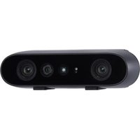
Gemini 2 - 3D Printer Orbbec - Free user manual and instructions
Find the device manual for free Gemini 2 Orbbec in PDF.


| Product Type | 3D Camera (Depth Sensor) |
| Model | Gemini 2 (G20155-15) |
| Technology | Active Stereo IR |
| Dimensions | 90 mm x 25 mm x 30 mm |
| Weight | 97 g |
| Power Connection | USB Type-C (USB 3.0 & USB 2.0) |
| Power Consumption | Average < 2.0 W, Peak 7.0 W |
| Depth Resolution | Up to 1280 x 800 at 30 fps |
| RGB Resolution | Up to 1920 x 1080 at 60 fps |
| Depth Range | 0.15 m to 10 m (optimal 0.20 m to 5.0 m) |
| Field of View (Depth) | 91° Horizontal x 66° Vertical |
| Depth Accuracy | ≤ 2% at 2 m (1280 x 800) |
| IMU | 6 DoF, 50–2000 Hz |
| Operating Temperature | 0°C to 40°C |
| Humidity | < 95% RH (non-condensing) |
| Laser Safety | Class 1 (IEC 60825-1) |
| Certifications | RoHS, FCC, CE, REACH, KC |
| Mounting | 1x 1/4-20 UNC, 2x M3 |
| Cable Length | Included USB-C cable; recommended up to 15 m with certified cable |
| SDK | Orbbec SDK (available at orbbec3d.com) |
Frequently Asked Questions - Gemini 2 Orbbec
User questions about Gemini 2 Orbbec
0 question about this device. Answer the ones you know or ask your own.
Ask a new question about this device
Download the instructions for your 3D Printer in PDF format for free! Find your manual Gemini 2 - Orbbec and take your electronic device back in hand. On this page are published all the documents necessary for the use of your device. Gemini 2 by Orbbec.
USER MANUAL Gemini 2 Orbbec
| Product Brief | 02 |
| Product Specifications | 02 |
| Product Information | 04 |
| SDK | 05 |
| Camera Setup and Operation | 05 |
| Installation Guide | 05 |
| Safety and Handling | 06 |
| Product Drawings | 06 |
| Principles of Depth Field of View | 07 |
| Multi-Camera Synchronization | 07 |
| Glossary of Terms | 08 |

natural_image
Front view of a black video camera with three lens modules and a small square light source (no text or symbols visible)1. Product Brief
Product Overview
The compact Gemini 2 3D camera, released in 2023, is based on Active Stereo IR technology and is equipped with Orbbec's latest custom ASIC for high quality depth processing, IMU, and single cable USB 3.0 power + connectivity. The wide FOV and the wide depth sensing range makes Gemini 2 adaptable for many applications, especially for robotics. It is easy to set up and operate with the Orbbec SDK and delivers extremely accurate and reliable data in various lighting conditions from pitch black to semi-outdoor.
Product Features:
- Wide Field of View at 91^ Horizontal and 66^ Vertical
• High quality depth data output from 0.15m to 10m - Up to 30 fps at 1280X800 depth resolution
- USB Type-C for power and data connectivity
• Multi-camera synchronization and IMU supported
2. Product Specifications
| Parameter Specifications | |
| Model G20155-15 | |
| VID/PID 0x2BC5/0x0670 | |
| Technology Active Stereo IR | |
| Shutter Type IR: Global Shutter; Color: Rolling Shutter | |
| Wavelength 850nm |
Product Specifications (continued from previous page):
| Mode | Resolution | FoV | FPS | Range | Format |
| Unbinned Dense Default | 1280 x 800 H | 91° x V 66° | 5, 10, 15, 30 | 15m - 10m (Optimal Range)0.20m - 5.0m | Y16/Y14 /RLE |
| 640 x 400 5, | 10, 15, 30 | ||||
| 320 x 200 5, | 10, 15, 30 | ||||
| Unbinned Sparse Default | 1280 x 800 5, | 10, 15, 30 | 0.15m - 10m | (Optimal Range)0.20m - 5.0m | |
| 640 x 400 5, | 10, 15, 30 | ||||
| 320 x 200 5, | 10, 15, 30 | ||||
| Binned Sparse Default | 640 x 400 5, | 10, 15, 30, | 60 | (Optimal Range)0.15m - 2.5m | |
| 320 x 200 5, | 10, 15, 30, | 60 | |||
| RGB 1920 x | 1080 16:9 | H 86° x V 55° | 5, 10, 15, 30, 60 YUYV/ | MJPEG | |
| 1280 x 720 5 | 10, 15, 30, 4:3 | 60 | |||
| 640 x 480 | H 63° x V 50° | 5, 10, 15, 30, 60 | |||
| 640 x 360 | 5, 10, 15, 30, 60 | ||||
| Depth Accuracy: ≤ 2% (1280 x 800 @ 2m & 81% ROI).The test object is a reflectivity >80% plane, and the reference range is 81% FoV (81% FoV is the remaining center 81% of the depth map area after cropping 5% of the top and bottom of the depth map).The root mean square of the distance sequence from all valid points in the area to the best-fit point of the fitted plane is calculated.Measure object reflectivity >10%, up to 10m distance depth data, but the actual accuracy varies with the distance and the object to be measured. | |||||
| Parameter | Specifications |
| Baseline | 50mm |
| IMU | 6 DoF; Frequency range: 50–2,000Hz; Data format: float |
| Mirror Mode | Supported, non-mirror by default |
| Processing | Internal processing using Orbbec MX6600 ASIC |
| Data Connection | USB 3.0 & USB 2.0 Type-C for data and power |
| Operating Modes | Unbinned Dense Default: High accuracy high quality depth data. Unbinned Sparse Default: Balanced depth accuracy and power consumption. Binned Sparse Default: Low power mode, supports 60fps, small blind zone. |
| Power Consumption | Average < 2.0W (Peak 7.0W) |
| Operating Environment | 0° – 40°C, <95 %RH (non-condensing), Indoor/Semi-Outdoor; IP5X |
| Anti-flicker | 50Hz & 60Hz |
| Supported Functions | D2C, Multi-Camera Sync |
| Dimensions | 90mm x 25mm x 30 mm |
| Weight | 97g |
| Certifications | Class 1, RoHS, FCC, CE, Reach, KC |
| Installation | 1 x 1⁄4-20 UNC 2 x M3 |
3. Product Information
3.1 Product Images
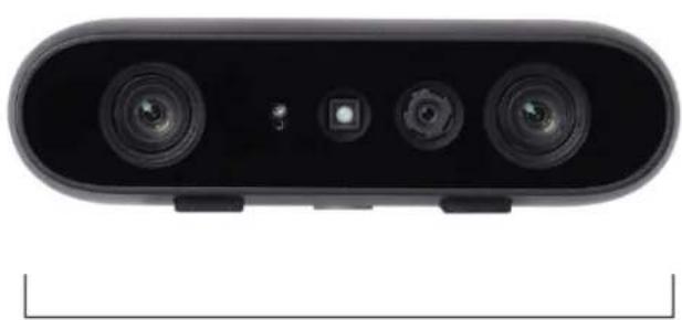
natural_image
Front view of a black electronic device with three lens modules and a small square button (no text or symbols visible)Product Picture
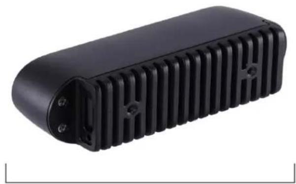
natural_image
Black plastic enclosure with ribbed heat sink and mounting holes (no text or symbols visible)Rear View
3.2 Product Components

Gemini 2 Components
3.3 Product Interfaces
The hardware interfaces of Gemini 2 camera are shown in the figure below.

4. Software Development Kit (SDK)
Orbbec SDK is a flexible and modular platform for easy camera setup and runs on multiple platforms with a rich set of APIs. It supports camera access; device setup and configuration; data stream reading, processing, and viewing; RGB-D registration; and frame synchronization.
5. Camera Setup and Operation
Packing List
• Orbbec Gemini 2 device
- USB Type-C to USB Type-C data + power cable
Initialization and Operation
- Connect Gemini2 via the cable to the host PC.
- Download Orbbec SDK from https://orbbec3d.com/developers/orbbec-sdk/
- Use Orbbec Viewer to validate that images can be streamed from all sensors with the following settings:
• Depth camera: Unbinned Dense Default, 1280x800 - RGB Camera: 1080p
- IMU enabled
- If for any reason that the camera is not responding or not being detected, please unplug all cables from the camera and replug to the host PC to reset the camera state.
Included functions:
- Access and control of camera devices.
• Control of frame synchronization and alignment.
• Acquisition of point cloud data.
• Orbbec Viewer for camera testing
Please check https://orbbec3d.com/developers/orbbec-sdk/ for the latest SDK.
Temperature sensor and recording
The temperature of camera core components — including laser temperature, IR sensor temperature, and IMU sensor temperature — can be obtained through API commands.
(Max case back temperature when operating in 40°C ambient environment: 50°C)
6. Installation Guide
Use outside of the specified conditions could cause the device to fail and/or function incorrectly. These conditions are applicable for the environment immediately around the device under all operational conditions. When used with an external enclosure, active temperature control and/or other cooling solutions are recommended to ensure the device is maintained within these ranges.
a. Installation Recommendations
- When using external housing around the camera for dust proofing, use foam inserts or rubber gaskets between the front of the camera and the external housing.
- Avoid the application of external forces to the camera chassis during the installation process.
- Disassembling chassis and mounting brackets will void the warranty.
b. Heat Dissipation
- Avoid any direct heat sources around the camera.
- Maximizing the space inside the external housing may help lower operating temperature.
c. Transmittance Requirements
The current light transmission of the Gemini 2 front cover glass lens is as follows:
- RGB (420\~650nm) transmittance rate ≥91%
- IR LDM (858 ±20nm) transmittance rate ≥92%
- LDP (940nm±30) transmittance rate ≥92%
Before changing the structural design of the camera, the protective lens in front of the camera lens must meet the requirements above.
d. Cable Design Guide
It is recommended to use the included USB Type-C cable. If a longer cable is needed, please select a USB certified cable that supports both power and data (1-15m length is recommended).
7. Safety and Handling
- Follow the instructions to operate the camera. Improper operation may cause damage to internal components.
- Do not drop or hit the camera with external force.
- Do not attempt to modify the camera as such modifications may cause permanent damage or inaccuracy.
- The temperature of the camera may increase during long periods of continuous usage.
- Do not touch the lens. Fingerprints on the lens may affect image quality.
6 Keep the product beyond the reach of children or animals to avoid accidents. - If the camera is not recognized by the computer, check if the cable meets the power/data transfer requirements and reinsert the USB cable for reconnection.
- This product uses a Class I laser. Looking at the laser for more than 20s is not recommended.
8. Product Drawings

Front View

Bottom View
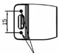
M2 Thread Mounting Points of Type-C Cable
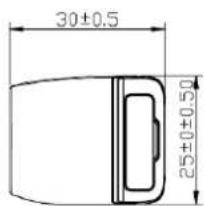
Side View
9. Principles of Depth Field of View
The image below shows the depth camera field-of-view, or the angles that the sensors "see". This diagram shows the IR camera.

Depth Field of View (Depth FOV) at any distance (Z) can be calculated using the following equation:
ZO = (B/2) / (ActiveH - FoV / 2) H - FoV = (cx/fx - B/Z) + ((width - 1 - cx)/fx) Active H - FoV = (cx/fx) + ((width - 1 - cx)/fx)
Definitions:
- cx = X-direction image coordinates of the main point of the depth image
- fx = Depth camera focal length
- width= Depth image width
- Active H-FoV = IR H-FoV
Note: cx, fx, and width parameters are obtained through the SDK Depth Intrinsic for the relevant camera parameters, and each 3D camera parameters are not the same.
10. Multi-Camera Synchronization
Advantages of multi-camera setup
- Increase camera coverage in the given space and fill in the occlusions where a single camera may have blind spots.
• Capture multiple images of the same scene and scan objects from different angles. - Increase the effective frame rate to greater than 30 frames per second (FPS).
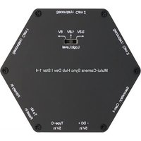
Using an 8-pin connector and matching cable, a multi-camera and multi-sensor network can be designed. (Please follow the instructions in the SDK).
Multi-camera frame synchronization in two topologies, including depth image synchronization and RGB image synchronization (time difference ≤ 3ms, when auto exposure off), using the multi-camera synchronization function.
Synchronization Interfaces of Gemini 2 Camera
| Pin Definitions Description | ||
| Pin_1 VCC | The default electrical level setting is 1.8V; when 3.3V or 5V drive voltage is provided on the VCC interface, the I/O level setting can be adjusted to 3.3V or 5V as required | |
| Pin_2 GPIO_OUT | Synchronization drive signal: Active high. The high-level interval coincides with the IR exposure time. Typical application is to drive external fill light | |
| Pin_3 VSYNC_OUT | Synchronous trigger signal: Active high. The high level provides the triggering signal for the secondary devices. | |
| Pin_4 TIMER_SYNC_OUT | Pulse signal source, reset hardware timestamp of secondary devices. | |
| Pin_5 RESET_IN | Hardware reset signal: Triggers the camera to power down and automatically power up and reset. Detect the input signal: 20Hz / 50% duty cycle / more than 5 consecutive cycles, that is, judged as normal input signal, other signals filtered out; allowed fluctuations for frequency ± 1Hz, duty cycle ± 2%. | |
| Pin_6 VSYNC_IN | Synchronous trigger signal: Active high, used for the triggering/sync signal from primary device, with a duration of IMS | |
| Pin_7 TIMER_SYNC_IN | Hardware timestamp reset signal input, hardware timestamp clearing | |
| Pin_8 GND | Ground | |

*The Pin sequence is shown with camera placed in rear view.
11. Glossary of Terms
| Term Definition | |
| D2C | Depth to Color function maps each pixel on depth map to the corresponding color image according to the intrinsic and extrinsic parameters of depth camera and color camera. |
| Depth | Depth video streams are like color video streams except each pixel has a value representing the distance away from the sensor instead of color information. |
| Depth Camera | Includes depth imaging module and external interface only, of which the former is generally composed of infrared projector, infrared camera and depth computing processor. |
| FOV | Field of View (FoV) describes the angular extent of a given scene that is captured by a camera, which can be measured in horizontal, vertical, or diagonal. |
| I2C | I2C bus refers to a kind of simple bidirectional two-wire synchronous serial bus developed by Philips. It can be used for transferring information among devices connected to the bus with two wires. |
| IR Camera | Infrared camera. |
| IR Flood | IR floodlights are used to illuminate the environment. |
| ISP | Image Signal Processor, which is used for image post-processing. |
| MIPI | Mobile Industry Processor Interface (MIPI) is an open standard and specification formulated by the MIPI Alliance for mobile application processors. |
| PCBA | Circuit board consists of depth computing processor, memory, and other electronic devices. |
| Point Cloud | A point cloud is a discrete set of data points in space. |
| SoC | System on Chip, integrated circuit (IC) that integrates all components of a computing system. |
| TBD | To Be Determined. In the context of this document, information will be available in a later revision. |

natural_image
Abstract pattern of blue circles arranged in a symmetrical radial shape (no text or symbols)ORBBEC
Copyright Orbbec Inc. All rights reserved. The product described may contain defects or errors or deviation from published specifications. Contact your sales representative to obtain the latest Orbbec 3D product specifications. Orbbec is not responsible for any users infringing on third party copyright or other rights in use of Orbbec products. In addition, Orbbec does not assume any liability for damages or any losses resulting from the use of this product. All information provided here is subject to change without notice.

- Product Brief
- Product Overview
- Product Features:
- Product Specifications
- Product Information
- Product Interfaces
- Software Development Kit (SDK)
- Camera Setup and Operation
- Packing List
- Initialization and Operation
- Included functions:
- Temperature sensor and recording
- Installation Guide
- a. Installation Recommendations
- b. Heat Dissipation
- c. Transmittance Requirements
- d. Cable Design Guide
- Safety and Handling
- Product Drawings
- Principles of Depth Field of View
- Definitions:
- Multi-Camera Synchronization
- Advantages of multi-camera setup
- Glossary of Terms
- ORBBEC
Brand : Orbbec
Model : Gemini 2
Category : 3D Printer