PPE4.B-15 - Chauffe-eau et chaudière KOSPEL - Free user manual and instructions
Find the device manual for free PPE4.B-15 KOSPEL in PDF.

| Product Type | Water Heater and Boiler |
| Brand | Kospel |
| Model | PPE4.B-15 |
| Power Rating | 4 kW |
| Capacity | 15 Liters |
| Voltage | 230 V ~ 50 Hz |
| Current | 17.4 A |
| Dimensions (H x W x D) | 600 x 400 x 400 mm |
| Weight | 15 kg |
| Temperature Range | 30 °C to 75 °C |
| Protection Class | IP24 |
| Mounting Type | Wall-mounted |
| Main Functions | Heating, Thermostat Control, Safety Valve |
| Maintenance | Descaling recommended annually |
| Safety Features | Overheat Protection, Pressure Relief Valve |
| Spare Parts Available | Heating Element, Thermostat, Magnesium Anode |
| Energy Efficiency | Class B (typical) |
Frequently Asked Questions - PPE4.B-15 KOSPEL
User questions about PPE4.B-15 KOSPEL
0 question about this device. Answer the ones you know or ask your own.
Ask a new question about this device
Download the instructions for your Chauffe-eau et chaudière in PDF format for free! Find your manual PPE4.B-15 - KOSPEL and take your electronic device back in hand. On this page are published all the documents necessary for the use of your device. PPE4.B-15 by KOSPEL.
USER MANUAL PPE4.B-15 KOSPEL
Electric Instantaneous Water Heater
natural_image
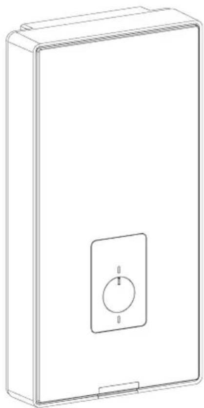
Line drawing of a rectangular electronic device with a circular button and mounting bracket (no text or symbols)PPE4.B
natural_image
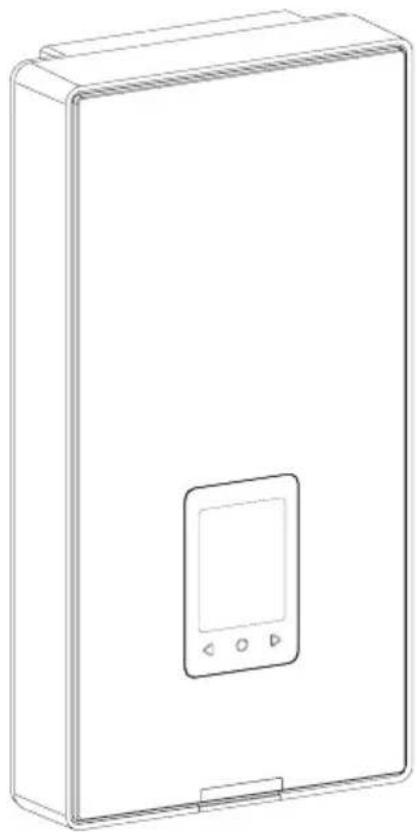
Line drawing of a rectangular electronic device with a central display and three control buttons (no text or symbols)PPE4.M
Inhaltsverzeichnis
text_image
Technical diagram of a device interior with numbered components and labeled parts, including a KOSPEL device.[1] - Basis
[2] - Heizeinheit
[3] - Druckschalter
[4] - Bedienfeld
text_image
Technical diagram of an electronic device with numbered components for assembly or maintenance reference.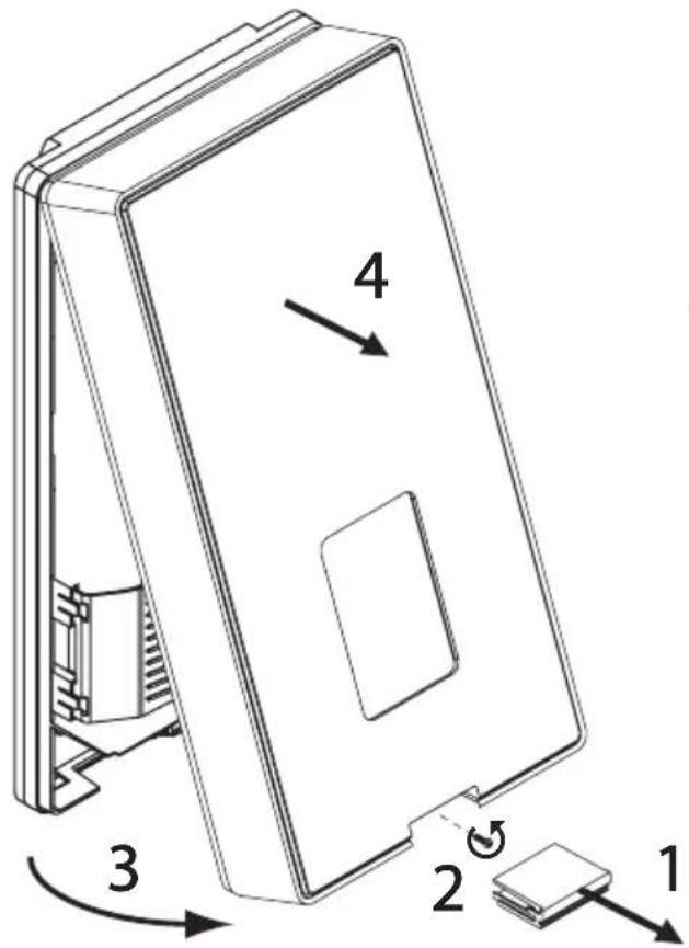
text_image
Technical diagram of a device with numbered components and directional arrows indicating assembly or movement.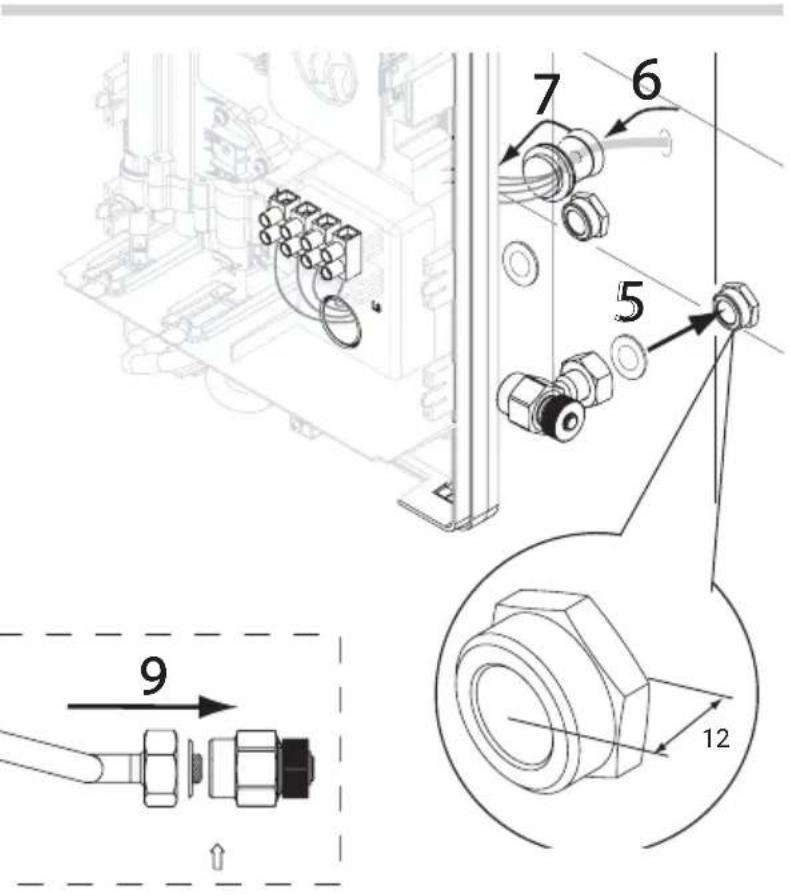
text_image
Technical diagram showing mechanical assembly with numbered components and a magnified view of a bolted joint detail.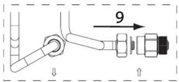
text_image
9text_image
on 1 2 3 4 5 6text_image
on 1 2 3 4 5 6text_image
on 1 2 3 4 5 6text_image
on 1 2 3 4 5 6text_image
on 1 2 3 4 5 6text_image
on 1 2 3 4 5 6text_image
on 1 2 3 4 5 6text_image
on 1 2 3 4 5 6natural_image
Technical line drawing of a mechanical component with two circular insets showing close-ups of internal parts (no text or symbols)natural_image
Symbol of a trash bin crossed with no text or numbers, representing waste sorting or disposal (no text present)Tekniske data (forts.) 51
text_image
Technical diagram of a device with numbered components and directional arrows indicating assembly or movement.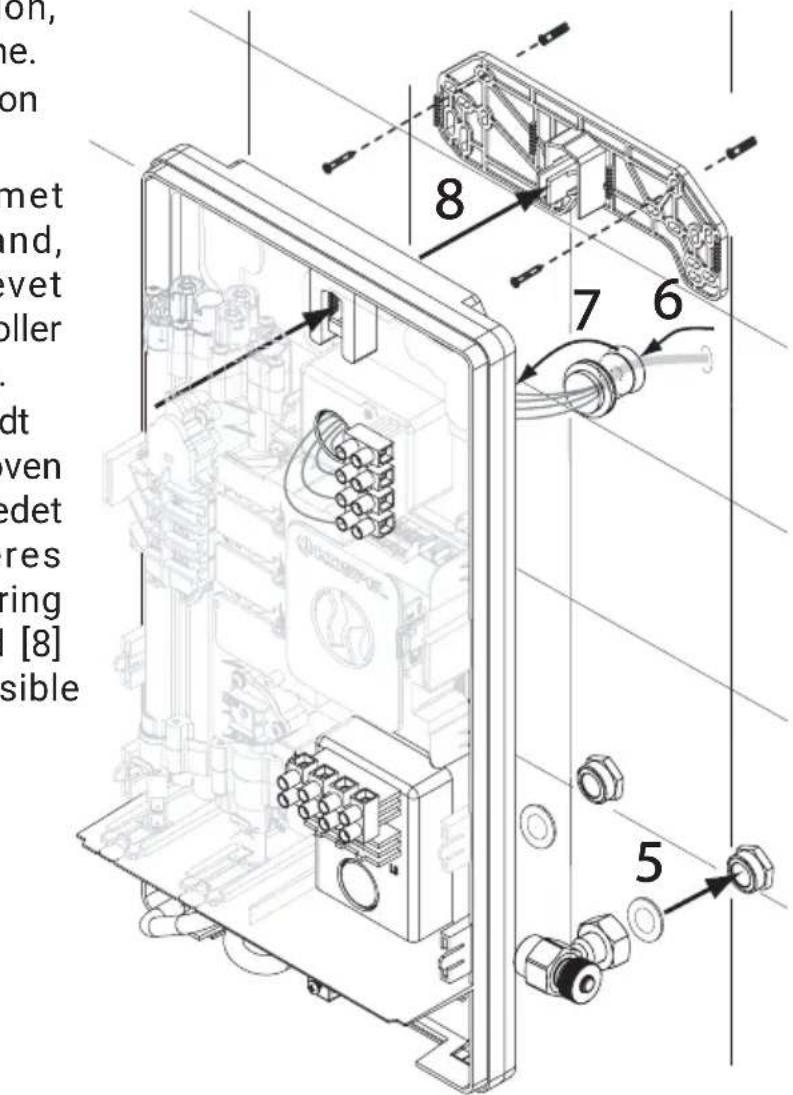
text_image
on, ne. on met nd, vet oller dt ven det res ring [8] sible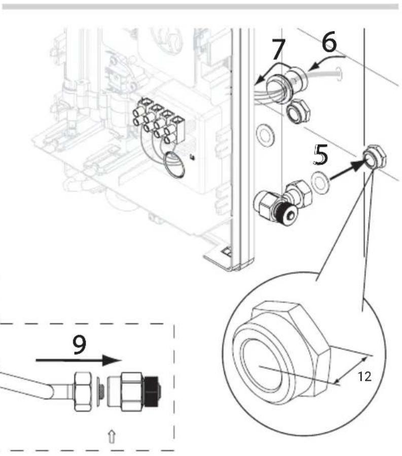
text_image
Technical diagram showing mechanical assembly with numbered components and a magnified view of a bolted joint detail.natural_image
Technical line drawing of a mechanical component with two circular insets showing close-ups of internal structures (no text or symbols)natural_image
Symbol of a trash bin crossed out by two crossed lines, with a solid black rectangle below (no text or labels)Explanation of symbols 55
Target group 55
Safety Guidelines 56
Safety Guidelines (cont.) 57
Product overview 59
Intended use 59
Product highlights 59
Construction 60
Installation 61
Bleeding air 63
Configuration 64
Commissioning and operating the PPE4.B 65
Commissioning and operating the PPE4.M 66
WiFi configuration - PPE4.M 72
Terminal block safety trip 73
Cooperation of the water heater with a hot water storage tank 74
Priority control relay operation 75
Maintenance 75
Technical specifications 76
Technical specifications (cont'd.) 77
Product disassembly 78
Packaging contents 78
Packaging disposal 78
Declaration of conformity; reference standards and directives 79
Data protection notice 79

Read this manual thoroughly before use.
Follow the manual to ensure safe and correct operation of the product.
Keep the manual for reference.

Follow the safety instructions carefully in order to prevent injury and damage.

Danger!
This sign warns against danger of injury.

Note!
This sign warns against property damage and environmental pollution.
Tip
Text marked with the word Tip contains additional information.

Refer to this manual when operating the product or its controls labelled with this symbol.
Target group

Note!
This manual is intended for the users of the product. This product can be operated by children at least 3 years old and individuals with impaired physical, sensory or mental capacity, or unexperienced and/or not knowledgeable in operation of the product only if instructed about its safe operation and understand all hazards involved. This product is not a toy for children. Children may only clean and maintain this product under supervision of an adult.
- Only qualified electricians may service electrical components.
- The first commission of this product for operation shall be done by the installer or a designated individual with suitable authorisation.
Applicable laws and regulations
• National electrical wiring and water plumbing installation codes.
• Statutory occupational hygiene and safety regulations.
• Statutory environmental protection regulations.
- Regulations of professional and insurance associations.
- Prevailing national safety regulations.
Product connection requirements
- The device is intended for installation only on a flat, vertical wall.
- The hydraulic and electrical installation must be designed and executed in accordance with the applicable regulations.
- The heater should be mounted to ensure easy service access. This also involves maintaining minimum distances of 150 mm from the walls and ceiling and at least 300 mm from the front cover to the nearest partition.
- The device must not be installed in rooms where the temperature can drop below 0°C, as this may cause permanent damage to the device.
- The device must not be installed in rooms with an explosion hazard.
- The use of plastic pipes on the inlet and outlet of the device is permitted, provided that the pipes used on the outlet have a minimum strength of 20 bar at a temperature of 70^ .
- A safety valve must not be installed on the domestic hot water system.
- The connection of the heater to the electrical network and the measurement of the effectiveness of the anti-shock protection (concluded with a protocol) must be performed by a qualified electrician.
- The heater must be unconditionally connected to the protective grounding, whose quality (continuity of the protective conductor) should be periodically checked (in accordance with the applicable regulations) by a qualified electrician. It is recommended to install the heater on grounded, steel, or copper hydraulic fittings.
-
According to general regulations, the electrical installation must be equipped with a high-sensitivity residual current device (with a maximum trip current of 30 mA), and it is recommended to install a separate four-pole residual current device (independent of the rest of the installation) in the heater's power supply circuit with a current of 10 or 30 mA.
-
The electrical installation should be equipped with means to disconnect the device from the power source, with a distance between the contacts of all poles of not less than 3 mm.
- The electrical installation must be equipped with at least class B surge protection.
Working with this product
- The heater may be operated only if it has been properly installed and its technical condition is perfectly fit for operation.
- The maximum water temperature at the heater outlet (supply end) shall not exceed 60°C.
- Before commissioning the heater for the first time and each time the heater has been emptied of water (e.g. due to maintenance servicing of the water plumbing), the heater shall be bled of air as explained in “Bleeding air”.
- Storage of the water heater in a room where the ambient temperature may fall below 0^ C may damage the heater (resides of water can be present in the heater; if frozen, it will burst the heater internals).
- Failure to install a strainer on the cold water inlet of the heater may result in failure of the product.
• Water scale deposits accumulating on the heater internals may restrict the water flow or result in failure of the heater.
All warranty claims caused by such failure will be rejected.
The heater and sanitary tapware shall be periodically descaled at a frequency which needs to be determined by the water hardness level.
- The minimum water resistivity at 15°C for the PPE4 heater shall be 900 Ωcm.
- The device must be permanently connected to the electrical installation.
- The device must be grounded.
Operation of the product

Danger!
Note that water at more than 40^ C is uncomfortably hot (especially to children); at temperatures above 50^ C, hot water is a risk of scalding, resulting in 1st degree burns (especially in children).

Danger!
Every time there is a water outage in the supply system of the heater, always disconnect the heater from electrical power and bleed air from the heater. Starting the water heater with no water supply to it may result in failure of the heater!

Danger!
Do not open the heater enclosure before isolating the power supply.

Danger!
Poor electrical wiring work may result in deadly hazards. Only qualified installers may service this product.
The PPE4 type electric instantaneous water heater is designed for heating domestic water in households, sanitary facilities, laboratories, workshops, etc. The heater is multi-tapped, allowing heated water to be supplied to multiple points of use (sink, washbasin, bathtub, shower, etc.), although the number of simultaneously used water points is limited by the maximum capacity of the device. Opening the hot water valve automatically starts heating the water to the set temperature. The device's control system maintains a constant set temperature. The limitation is the maximum capacity of the heater (see technical data table). The maximum temperature of the water supplied to the heater must not exceed 60°C.
Intended use
The device is intended solely for domestic or similar use. Commercial or industrial applications causing excessive usage of the device are not in accordance with its intended purpose. Improper use of the device or unprofessional handling is prohibited and will result in the manufacturer disclaiming any responsibility. Improper use also includes altering the intended function of the heating system components.
Hint
The product is intended for private household or similar use only, which means that even untrained people can safely handle the product.
Product highlights
LCD panel (PPE4.M option only)
- Inlet & outlet temperature display
- Flow rate display
- Current heat output display
• Maximum outlet temperature limit setting
• Memory of 3 most frequently used temperature settings
Electronic control
- Precise and convenient water temperature control
• Water temperature setting range 30-60°C in 1°C increments.
4 heat output settings in one heater
• Maximum heat output selectable.
text_image
Technical diagram of a device interior with numbered components and labeled parts, including a KOSPEL device.[1] - baseplate
[2] - heating unit
[3] - pressure switch
[4] - control panel
[5] - outlet port - DHW supply end
[6] - stop valve
[7] - inlet port - cold water end
[8] - power cable penetration (at the bottom)
[9] - lower terminal block
[10] - flow sensor
[11] - heat output & other setting DIP switches
[12] - LED indicators (from top to bottom: STATUS, HEATING ON, FLOW ON, ERROR)
[13] - card - communication module
[14] - power cable penetration (at the top)
[15] - upper terminal block
[16] - power cable rubber grommet
[17] - heater wall mounting bracket
text_image
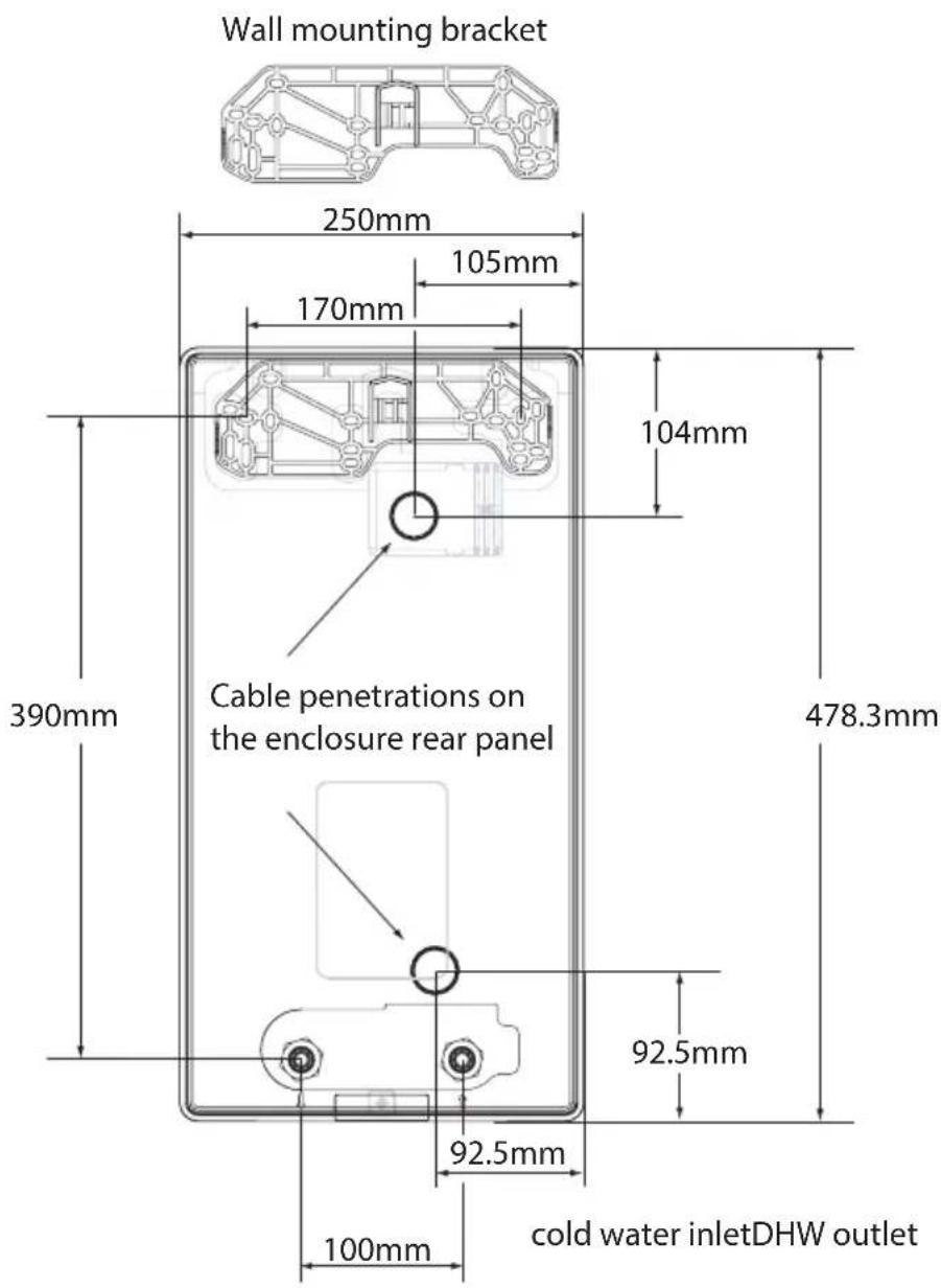
Wall mounting bracket 250mm 105mm 170mm 104mm 390mm Cable penetrations on the enclosure rear panel 478.3mm 92.5mm 92.5mm 100mm cold water inletDHW outlet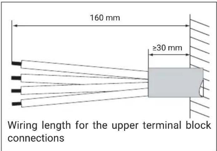
text_image
160 mm ≥30 mm Wiring length for the upper terminal block connections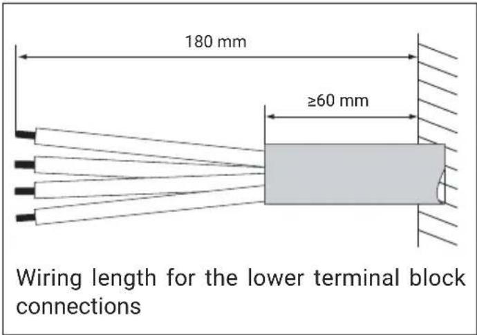
text_image
180 mm ≥60 mm Wiring length for the lower terminal block connections- Use the template to mark out the holes on the wall to be drilled for the wall mounting bracket.
- Lead the power wiring and water plumbing connections to the installation location.
- Remove the heater enclosure panels and inspect the technical condition; check for all damage in transport and verify that the terminal block safety trip is closed.
- The heater is factory-configured for wiring to the upper terminal block [15]. To change to the bottom terminal block wiring, move the upper terminal block to the bottom terminal block location [9].
text_image
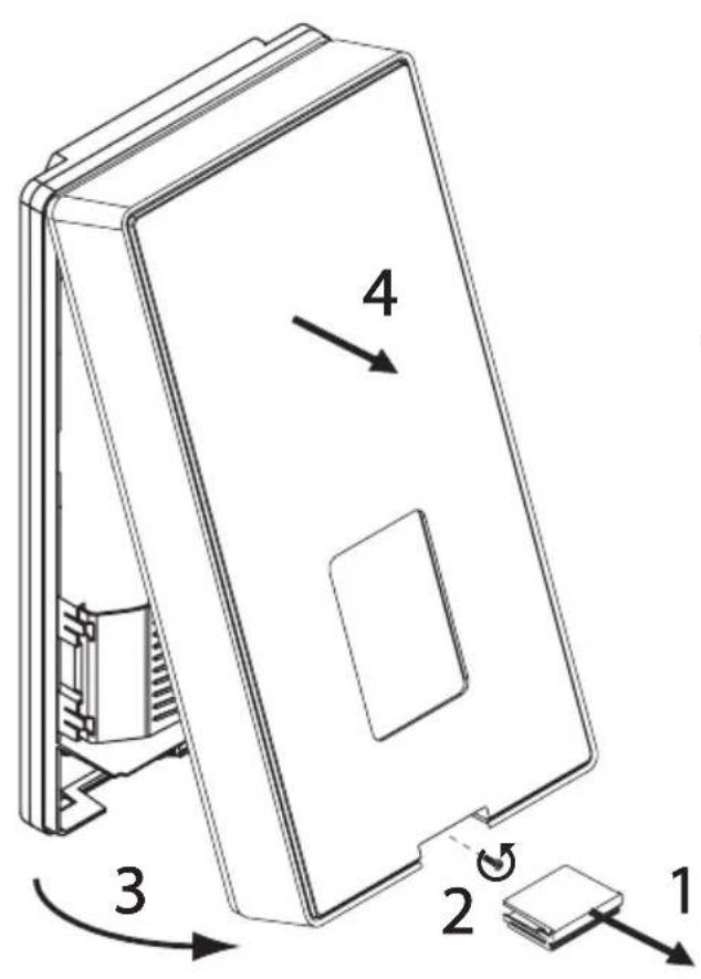
Technical diagram of a device with numbered components and directional arrows indicating assembly or movement.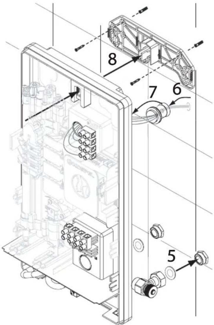
text_image
Technical diagram of an electronic device with numbered components for assembly or maintenance reference.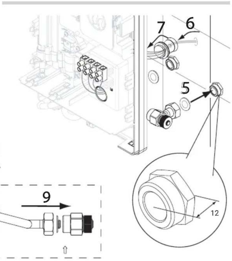
text_image
Technical diagram showing mechanical assembly with numbered components and a magnified view of a bolted joint detail.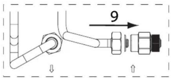
text_image
9Before proceeding with the installation process, break out the power cable penetration blank out of the housing in the suitable location [8] or [14] and install the rubber grommet [16] in the open penetration.
- Fasten the wall mounting bracket with the screws. Place the heater on the wall mounting bracket as shown in the figure once the power cable has been inserted through the penetration with the grommet installed. Do not handle the heater by its internals during the installation process.
- Remove the blind caps from the cold and DHW water ports.
- Connect the water heater to the water system plumbing.
- Open the cold water supply valve and inspect all water connections for leaks.
- Bleed air from the system, ref. "Bleeding air".
- Reinstall the enclosure on the heater.
- Make sure that no access to any live internals is possible through any openings in the back panel.
text_image
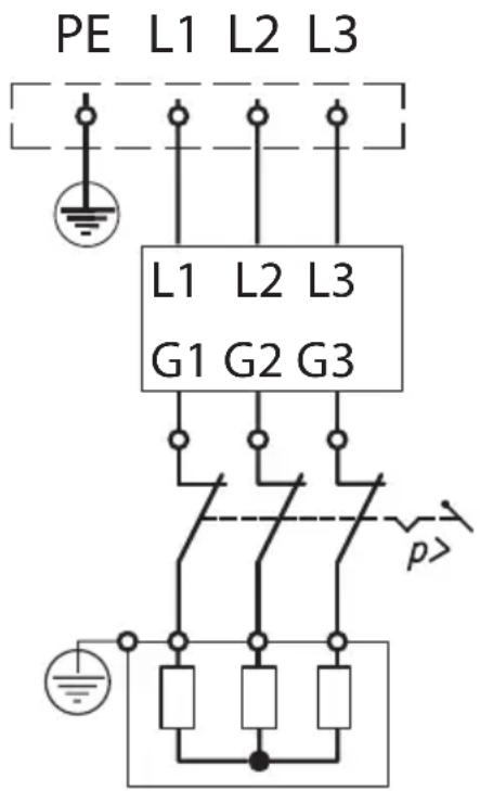
PE L1 L2 L3 L1 L2 L3 G1 G2 G3 p>Bleeding air

- Isolate the power supply from the heater.
- Open the water flow through the heater (by opening a hot water tap) and wait for the air to be bled out (for at least 30 seconds), after which the water should flow out of the tap with a steady stream without evidence of escaping air.
- Turn on the power supply.

Note!
Perform this procedure after every water supply outage.
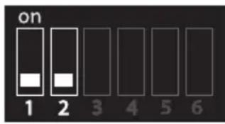 | 10kW setting for PPE4 - 10/11/12/1517kW setting for PPE4 -17/18/21/24 |
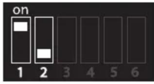 | 11kW setting for PPE4 - 10/11/12/1518kW setting for PPE4 -17/18/21/24 |
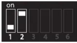 | 12kW setting for PPE4 - 10/11/12/1521kW setting for PPE4-17/18/21/24 |
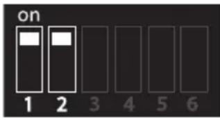 | 15kW setting for PPE4 - 10/11/12/1524kW setting for PPE4 - 17/18/21/24 |
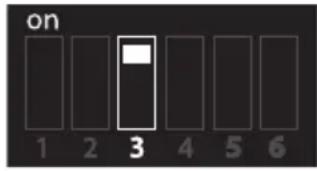 | Maximum DHW outlet temperature setting at 52°C (SHOWER) |
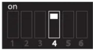 | Blocking the possibility of changing the temperature setting (does not apply to version B) |
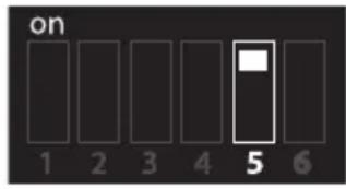 | Disabling air detection with the probe (DO NOT SWITCH!) |
 | Disabling triac damage detection (DO NOT ADJUST!) |

Note!
The heater is has a factory setting to NORMAL 60°C mode. Changing the operating mode to SHOWER 52°C is done only by an authorized service.
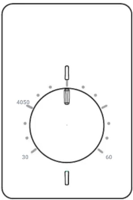
text_image
4050 30 60The heater automatically starts heating water when the flow exceeds 1.8 l/min. The control system adjusts the appropriate power of the heater based on the water consumption rate, the set water temperature, and the inlet water temperature. Stopping the water flow automatically turns off the water heating.
The water heater enclosure features LED indicators:
- the green LED comes on with the mains power supply,
- the red LED comes on with the heater output that produces DHW.
Fault conditions which lock out the heater from operation are indicated with a specific flashing pattern of the green LED indicator (interpretation, see the reference table below).

Danger!
Simultaneous blinking of the green and red indicators indicates a critical device failure. It is necessary to disconnect the electrical power.
| Green LED flash count | Status |
| 1 | - Inlet temperature sensor failure- Outlet temperature sensor failure- Temperature sensor connections reversed |
| 2 | - Air clog detected in the resistive heater system; heat output disabled |
| 3 | - Outlet water overtemperature- Outlet flow rate too high |
| 4 | - Power supply grid sync failure- Hardware configuration error |
| 5 | Information / warning:- Actual heat output is not as set- Temperature sensor response altered- Actual temperature of a sensor too low or too high |
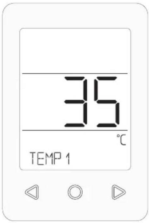
text_image
35 TEMP 1After turning on the power supply, the panel software version will appear on the display, followed by the controller software version along with the set heater power.
Before the first heating, the control system waits for stabilisation of the parameters, which is indicated by and a message.
The heater automatically starts heating water when the flow exceeds 1.8 l/min. The control system adjusts the appropriate power of the heater based on the settings, water consumption rate, and inlet water temperature. When on, the heat output is indicated by the LCD panel coming on and displaying the icon. The LCD panel comes on when the user begins to interact with it. The LCD panel reverts to the sleep mode when the heat output is turned off or when there is no user interaction for 1 minute.
| Icons | |
| An event which affects the operating comfort of the heater | |
| An error which locks out the heat output. | |
| Water flow rate/consumption display | |
| Heater WiFi connection established | |
| Service menu mode enabled | |
| Pause forced by the control system | |
| Access to heater parameter settings enabled | |
| Electric power input display | |
| Heating on display; if flashing, the temperature setting cannot be achieved even with the maximum heat output | |
| The parameter setting input is out of range or the command input attempted is locked out | |
| Main menu | |
| TEMP 1 | Temperature setting mode.○ Subsequent pressing is the choice of three recorded temperatures,△ Change in the set value,○ Hold to open the parameter setting overview. |
| TEMP 2 | |
| TEMP 3 | |
| Parameter setting overview | |
| POWER | Actual heat output. |
| TEMP IN | Cold water inlet temperature. |
| TEMP OUT | Hot water outlet temperature. |
| SET TEMP | DHW temperature setting. |
| FLOW | Actual water flow rate. |
| SET POWER | Heat output setting. |
| ENERGY | Electrical power input:○ Opens the overview, ◀ Modifies the input range, JAY, WEEK MONTH YEAR ENI Returns to the overview menu. |
| WATER | Water consumption:○ Opens the overview, ◀ Modifies the input range, JAY, WEEK MONTH YEAR ENI Returns to the overview menu. |
| WIFI | WIFI signal level, WiFi module number. |
| INFO | [SERVICE ACCESS ONLY] Displays the control logic status and the heat output lockout password. |
| WARNINGS | [DISPLAYED WHENEVER PRESENT].○ Displays the active warnings, ◀ Cycles through the next active warnings, ENI Returns to the overview menu. |
| ERRORS | [DISPLAYED WHENEVER PRESENT].○ Displays the active failures which lock out the heat output, ◀ Cycles through the next active errors, ENI Returns to the overview menu. |
| SYSTEM | Current firmware versions of the LCD panel, the control unit, and the WiFi module. |
| CONFIG | ○ Opens the configuration menu. |
| ENI | Leaves the overview menu and opens the main menu. |
| Configuration | |
| TEMP 1TEMP 2TEMP 3 | Selects one of the three most often used temperature settings.○ Opens the setting mode,◀ ▶ Modifies the setting value,○ Set saved and return to the configuration menu. |
| LCD MIN | ○ Opens the LCD backlight level setting for the sleep mode.◀ ▶ Changes the setting value,○ Returns to the configuration menu. |
| LCD MAX | ○ Opens the LCD backlight level for the active mode and the heat output on mode.◀ ▶ Changes the setting value,○ Returns to the configuration menu. |
| ENGLISH | Changes the interface language.○ Activates the change,◀ ▶ Changes the language,○ Exits the submenu. |
| TEMP MAX | Maximum DHW outlet temperature setting.○ Opens the setting mode,◀ ▶ Changes the setting value,○ Exits the submenu. |
| DATE TIME | DATE TIME System date and time settings.○ Opens the setting mode,◀ ▶ Selects the parameter setting to be modified,YEAR,MONTH JAY HOUR○ Opens the parameter setting mode,◀ ▶ Changes the setting value,○ Returns to the parameter setting selection,EN□ Returns to the configuration menu. |
| WIFI | WiFi connectivity menu.○ Opens the menu,WIFI CONFIG○ Start of the connection pairing (the LCD screen displays the configured timeout countdown; if the connection is successful, the connection signal strength is displayed; if unsuccessful, the display reads — — ),EN□ Returns to the configuration menu. |
| SYSTEM | ○ Opens the command selection menu.◀ ▶ Possible selections:RESET - Restarts the controls,FACTORY SET - Restores the factory default settings,EN□ Returns to the configuration menu. |
| DISINFECT | Opens the disinfection menu, which is password-protected [23].Change of the item.DISINFECT - Disinfection heating temperature setting.Opens the setting mode,Changes the setting value,Return.DESIN START - Enables the disinfection function Activation start (the heater will heat the water to the set temperature DISINFECT value in one, the nearest heating cycle, but not later than 15 minutes from setting).DESIN STOP - Exits activation - if the function is active.Stops activation,END Exits the submenu. |
| SERVICE | Access to the service mode: for qualified service technicians only. |
| END | Leaves the configuration menu and opens the main menu. |
| Information messages | |
| LOW FLOW | Information about too low flow to turn on the heating. |
| WAIT | System during configuration. |
| COM MSP | No connection to the controller. |
| Error display | ||
| kod Possible causes Solutions | ||
| E01 Power Off | - One or more triacs have failed. | ISOLATE THE PRODUCT FROM THE POWER SUPPLY and contact the technical service. |
| E02 TIN | - Tin sensor failure,- Tin sensor missing,- Tin sensor connection short to ground. | Verify that the harness connector is in the correct receptacle; if it is, contact the technical service. |
| E03 TOUT | - Tout sensor failure,- Tout sensor missing,- Sensor connection short to ground,- Tout. | Verify that the harness connector is in the correct receptacle; if OK, contact the technical service. |
| E04 OUT/IN | - Tin and Tout sensor connections reversed,- Altered response of one or both temperature sensors. | Verify the temperature sensor connections are as assigned;if OK, contact the technical service. |
| E05 AIR2 | - Air clog in the water circuit- Vane flow meter dirty,- Vane flow meter failure. | if the problem persists, contact the technical service. |
| E06 AIR | - Air clog in the water circuit,- Pressure switch triggered;- Voltage lost on one supply phase. | Verify all supply phase voltages are correct;if the problem persists, contact the technical service. |
| E07 T MAX | - ransient flow rate fluctuations,- High/sudden setting changes,- Control system failure. | if the problem persists, contact the technical service. |
| E08 FLOW | - Air clog in the water circuit,- Water supply system pressure too high. | if the water supply system pressure is within specification limits and the problem persists, contact the technical service. |
| E09 3F | - No mains grid sync signal input,- Supply phase voltage lost. | If the mains parameters to which the heater is connected are correct, contact the service. |
| E10 CONFIG | - Illegal hardware configuration. Contact the technical service. | |
| E11 Power Off | - Control system failure. | ISOLATE THE PRODUCT FROM THE POWER SUPPLY and contact the technical service. |
Warning display
| Code | Possible causes Solutions | |
| W01 | - E06 AIR1 error while heating. | if the problem persists, contact the technical service. |
| W02 | - E05 AIR2 error while heating. | if the problem persists, contact the technical service. |
| W03 | - E08 FLOW error while heating. | if the problem persists, contact the technical service. |
| W04 | - E07 T MAX error while heating. | if the problem persists, contact the technical service. |
| W05 | - Pressure switch tripped,- Incorrect DIP switch settings for the heating system,- Resistive heater failure,- Supply phase voltage lost,- Triac failure. | If the parameters of the power supply grid wired to the heater are within specification limits, contact the technical service. |
| W06 | Low battery. | Replace the battery or contact the technical service. |
| W07 | Battery drained. | Replace the battery or contact the technical service. |
| W08 | - Altered response of one or both temperature sensors. | Contact the technical service. |
| W09 | Control PCB failure. Contact the technical service. | |
| W10 | Control PCB failure. Contact the technical service. | |
| W11 | WiFi module failure. Contact the technical service. | |
| W12 | Control PCB failure. Contact the technical service. | |
| W13 | - Operation environment conditions out of limits,- Inlet temperature sensor failure. | - Verify the heater installation location is correct,- Verify the cold water supply temperature,- Inspect/replace the inlet temperature sensor or contact the technical service. |
| W14 | - If W13 and W15 are active at the same time, the installation location conditions are incorrect,- If W13 is active only, the cold water supply temperature is too low,- If W14 is active only, the outlet temperature sensor has failed. | Replace the outlet temperature sensor (only if W13 and/or W15 are not active at the same time). |
| W15 | - Operation environment conditions out of limits,- Control PCB failure. | - Verify the heater installation location conditions are within specification,- Contact the technical service. |
| W16 | - Operation environment conditions out of limits,- Inlet temperature sensor failure. | - Verify the heater installation location is correct,- Verify the cold water supply temperature,- Replace the inlet temperature sensor. |
| W17 | - Operation environment conditions out of limits,- Control PCB failure. | - Verify the heater installation location conditions are within specification,- Contact the technical service. |
Hint
If the module is not connected to the heater controller, the WiFi-related fields will not be available on the panel.
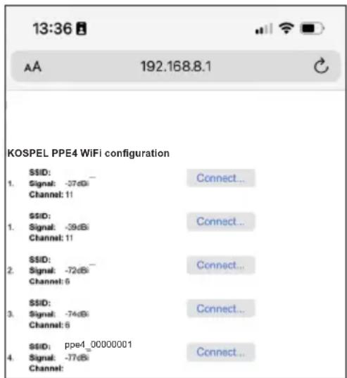
- Enter the menu and after selecting the , when the WIFI CONFIG WIFI message appears, press the Ⓐ key to start setting up the WiFi connection. A message will appear on the display and the time left to configure the connection using a phone or tablet is counting down.
- Start searching the network on your phone, tablet or computer, and then select the heater from the list of found devices (ppe4_0000xxxx). The module number can be read in the menu View >WIFI XXX parameters. After selecting the heater from the list, select the option to use the security key and enter the password 12345678. After establishing a connection, a message about unavailability of the Internet may appear on the screen of the device, please ignore it and maintain the connection.
text_image
13:36 AA 192.168.8.1 KOSPEL PPE4 WiFi configuration SSID: 1. Signal: -37dBi Channel: 11 SSID: 1. Signal: -39dBi Channel: 11 SSID: 2. Signal: -72dBi Channel: 0 SSID: 3. Signal: -74dBi Channel: 6 SSID: ppe4_00000001 4. Signal: -77dBi Channel: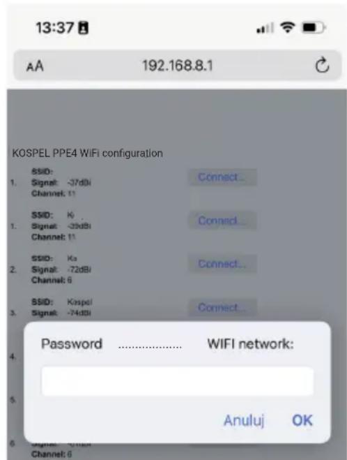
text_image
13:37 AA 192.168.8.1 KOSPEL PPE4 WIFI configuration SSID: Signal: -37dBi Connect... Channel: 11 SSID: Ki Signal: -35dBi Connect... Channel: 11 SSID: Ka Signal: -72dBi Connect... Channel: 6 SSID: Kaspel Connect... Signal: -74dBi Password ...... WIFI network: Anuluj OK- Launch the web browser, enter the address 192.168.8.1, the configuration page should be displayed in the window. If, after establishing connection with the module, you cannot open the configuration page, check whether other connections to the Internet are active (LTE, GPRS, etc.). In this case, temporarily disconnect your phone or tablet from the Internet and try to connect to the WiFi module again.
- In order to properly configure the connection, select the access point from the list displayed under the inscription „KOSPEL PPE4 Wi-Fi configuration.”
Under the SSID of the network, its signal strength is displayed.
If there are several access points in the network, choose the one with the best performance (that is, the lowest negative dBi value).
After pressing „Connect...“, a window will be displayed in which you should enter the password of the WiFi access point to which the heater is to be connected (e.g. WiFi router), and confirm it with the „OK” button.
- If after the configuration time appears on the heater panel, the connection has not been established. In this case, you can repeat the setup process by repeating the procedure from the beginning.
- If the WIFI signal level (1..100%) appears on the display, the connection to the WiFi network has been established and the procedure has been completed. You can download the free "Kospel PPE4" software from the app store (Android, iOS) and start remote work with the heater.
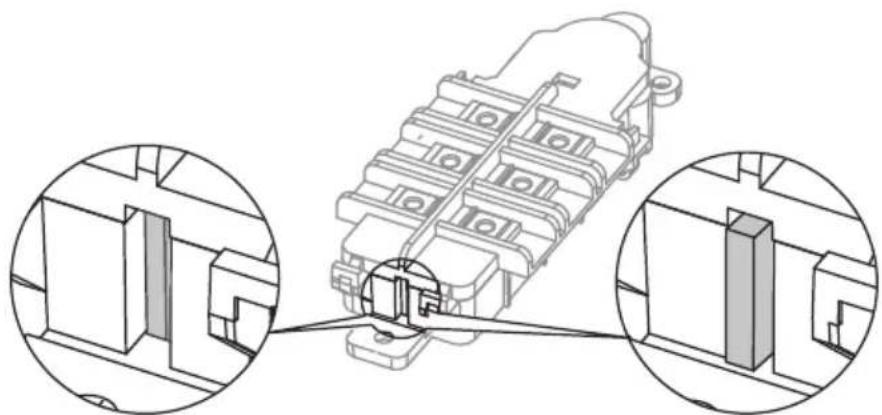
Terminal block safety trip
Note!
The terminal block safety trip can be tripped by pressure shocks or failure of the heater.

Danger!
If the terminal block safety trip cuts out, contact the technical service.
natural_image
Technical line drawing of a mechanical component with two circular insets showing close-ups of internal structures (no text or symbols)Safety trip enabled Safety trip cut out
Cooperation of the water heater with a hot water storage tank
The heater can operate in systems with preheated water. The recommended connection diagram for the storage tank with the heater is shown below.
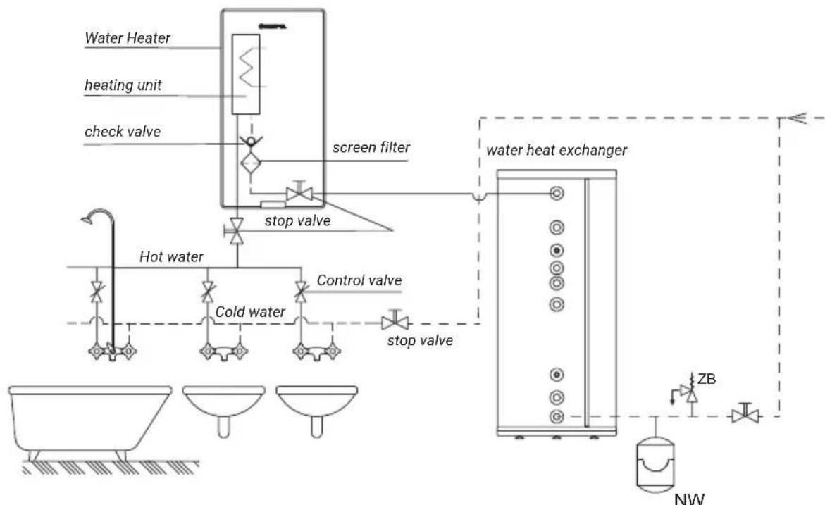
flowchart
graph TD
    A["Water Heater"] --> B["heating unit"]
    B --> C["check valve"]
    C --> D["screen filter"]
    D --> E["stop valve"]
    E --> F["control valve"]
    F --> G["stop valve"]
    G --> H["water heat exchanger"]
    H --> I["ZB"]
    I --> J["NW"]
    K["Hot water"] --> L["Cold water"]
    M["stop valve"] --> N["stop valve"]
Connection according to the diagram below is allowed. In this case, a check valve placed on the hot water outlet of the hot water storage tank is absolutely required. The use of a hot water circulation system is not allowed.
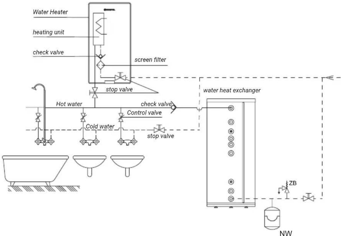
flowchart
graph TD
    A["Water Heater"] --> B["heating unit"]
    B --> C["check valve"]
    C --> D["stop valve"]
    D --> E["control valve"]
    E --> F["stop valve"]
    F --> G["water heat exchanger"]
    G --> H["NW"]
    I["Hot water"] --> J["Cold water"]
    K["screen filter"] --> L["stop valve"]
    M["stop valve"] --> N["stop valve"]
    O["water heater"] --> P["heating unit"]
If the power input of the loads connected to the power supply system prevents their simultaneous operation with the heater, a priority control relay must be installed.
Wire the heater terminal block L1 to the power supply source via the priority control relay. In this wiring configuration, the power loads wired to a non-priority power supply line will not turn on while the heater is heating DWH.
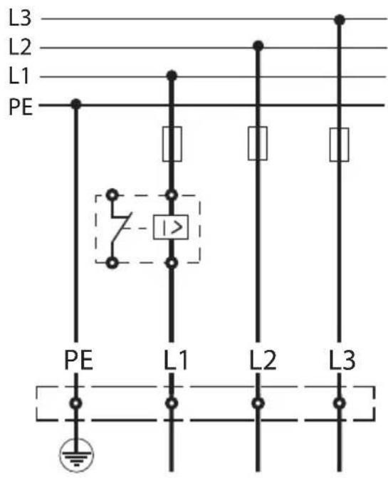
text_image
L3 L2 L1 PE PE L1 L2 L3 I>Maintenance

Cleaning the water strainer (can be done by unqualified personnel):
-
Isolate the power supply and close the cold water supply to the heater.
-
Remove the heater enclosure.
-
Remove the cold water inlet connection from the inlet port.
-
Remove the strainer from the cold water inlet port.
-
Clean the strainer.
-
Reinstall the strainer with the seal and connect the water supply to the inlet port.
-
Open the cold water supply stop valve and inspect for leaks.
-
Bleed air from the system, see "Bleeding air".
-
Reinstall the enclosure on the heater.
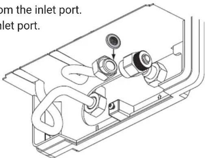
text_image
from the inlet port. Inlet port.
Danger!
Do not open the heater enclosure before isolating the power supply. Electrocution hazard.
| PPE4 water heater (all options) 10/11/12/15 17/18/21/24 27 | ||||||||||
| Power supply | 380V 3~ | |||||||||
| Rated power | kW 9 | 1 10 11 | 13,7 15,6 | 16,5 19 | 2 22 24,7 | |||||
| Nominal input current | A 3x | 13,8 3x1 | 5,1 3x16 | 7 3x20,7 | 3x23,6 | 3x25 3x2 | 9,1 3x33 | 3 3x37,4 | ||
| Power supply | 400V 3~ | |||||||||
| Rated power | kW 10 | 11 12 | 5 17 18 | 21 24 27 | ||||||
| Nominal input current | A | 3x14,5 | 3x15,9 | 3x17,3 | 3x21,7 | 3x24,7 | 3x26,0 | 3x30,3 | 3x34,6 | 3x39,0 |
| DHW output (at inlet water temperature of 30°C and pressure of 0.45 MPa) | l/min | 4,3 | 5,2 | 5,8 | 7,2 | 8,1 | 8,7 | 10,1 | 11,6 | 13 |
| Power supply wiring conductor minimum size | mm2 | 4 x 2,5 | 4 x 6 | |||||||
| Power supply wiring conductor maximum size | mm2 | 4 x 16 | ||||||||
| Power mains system maximum impedance | Ω | 0,43 0,37 | 0,30 | |||||||
| Declared load profile | XS | S S | ||||||||
| Daily power input Q_elec | kWh | 2,135 | 2,144 | 2,147 | ||||||
| Protection rating | IP25 | |||||||||
The minimum water resistivity at 15^ C for the PPE4 heater shall be 900 cm.
| Supply water pressure MPa 0,1 ÷ 1,0 | |||
| Heating start threshold(minimum flow rate) | l/min | 1,8 | |
| Control rangefor watertemperature | NORMAL mode | °C | 60 |
| SHOWER mode 52 | |||
| Water connection ports G 1/2" (port distance 100mm) | |||
| Sound power level L_WA | dB 15 | ||
| Overall dimensions(height x width x depth) | mm 478 x 250 x 99 | ||
| Weight kg ~3,8 | |||
| WiFi interface specifications PPE4.M | |
| Mode AP/Client 802.11b/g/n. | |
| Security WPA/WPA2 (personal) | |
| IP address assignment DHCP | |
| Frequency 2412-2484 MHz | |
| Transmission power <19,5 dBm |
Disassemble the product in the reverse order of the installation procedure on p. 61.
Packaging contents
PPE4 water heater 1 pc.
Wall mounting bracket 1 pc.
Gaskets 2 pc.
Screws 2 sets
Drilling template 1 pc.
Warranty certificate and installation certificate form 1 pc.
Packaging disposal
Recycle obsolete packaging according to the applicable regulations.
This product is labelled with waste segregation collection symbol, as established in EN 50419. This label also means that the product is marketed after 13 August 2005.

Households have an important contribution to reuse and recovery of materials, which includes recycling of waste electrical and electronic equipment (WEEE).
Proper disposal of WEEE contributes to environmental protection and helps recover recyclable materials.
All packaging materials for our products are recyclable and can be converted into more products.
This product once spent shall not be disposed with mixed household waste.
Return the product to a WEEE collection point for recycling. Proper disposal of the spent product prevents potential environmental impact from incorrect waste management.
For more detailed information on how to recycle this product, contact your local authorities, waste management operators or the original seller.
KOSPEL Sp. z o.o. hereby declares on its sole responsibility that type PPE4 electric tankless water heaters specified in this manual conform to European Directives and their corresponding safety standards for electric household appliances:
LVD (2014/35/EU)
EMC (2014/30/EU)
RED (2014/53/EU)
and bear the following symbol C€
The full version of this declaration of conformity is available on the manufacturer's
website: www.kospel.pl
Data protection notice
To use remote control and the remote control module of the heater, you need to download a free application.
Detailed information regarding personal data protection is available on the manufacturer's website at www.kospel.pl, under the „Privacy Policy” tab.
PPE4.M

KOSPEL Reparatur - Hotline 0241 910504 50