RG3-15CLS - Electric regulator ENTES - Free user manual and instructions
Find the device manual for free RG3-15CLS ENTES in PDF.


| Product Type | Power Factor Controller |
| Model | RG3-15CLS |
| Brand | ENTES |
| Dimensions (Panel Cut-out) | 139 x 139 mm (Type PR16) |
| Weight | 0.85 kg |
| Operating Voltage (Un) | See rear label (typical 110-250 VAC) |
| Power Consumption | <2 VA (current), 3-10 VA (voltage) |
| Number of Capacitor Steps | 12 |
| Measurement Parameters | Voltage, Current, Cosφ, Active/Reactive/Apparent Power, Energy, Harmonics up to 19th |
| Communication | RS-485 with MODBUS-RTU (RG3-12CS model, check manual) |
| Target Cosφ Setting Range | -0.800 to 0.800 |
| CT Ratio Setting Range | 1 to 2000 |
| VT Ratio Setting Range | 1 to 2000 |
| Switching On/Off & Discharge Time | 1 to 1800 seconds |
| Overvoltage Alarm Setting | 0-300 V (with Vtr=1) |
| Temperature Measurement (Optional) | J-type thermocouple, 0-100°C |
| Fan Relay (Optional) | Programmable on/off temperature |
| Protection Class | IP40 front panel, IP00 terminals |
| Installation | Flush mounting (panel mount) |
| Operating Temperature Range | -5°C to 55°C |
| Maintenance | Only by qualified electricians; clean with dry cloth; do not open housing |
| Safety Precautions | Disconnect current transformer before servicing; use correct fuses; follow connection diagram |
| Spare Parts & Repairability | No user-serviceable parts; contact seller for service |
Frequently Asked Questions - RG3-15CLS ENTES
User questions about RG3-15CLS ENTES
0 question about this device. Answer the ones you know or ask your own.
Ask a new question about this device
Download the instructions for your Electric regulator in PDF format for free! Find your manual RG3-15CLS - ENTES and take your electronic device back in hand. On this page are published all the documents necessary for the use of your device. RG3-15CLS by ENTES.
USER MANUAL RG3-15CLS ENTES
Precautions for Safe Use and Installation....1
Important Note for System Connection ....1
1. INTRODUCTION 2
1.1 General Information 2
1.2 Front Panel 2
1.3 Rear Panel 4
2. INSTALLATION OF RG3-12C/CS 5
2.1 Commissioning of RG3-12C/CS 5
2.2 Capacitor Sequence Process 5
3. SETTINGS 5
3.1 Manual Operation, Automatic Capacitor Recognition Mode and Automatic Connection Recognition Mode......5
3.2 Target Cos φ and Cosφ2Value Setting 7
3.3 Last Capacitor Step Number Setting 7
3.4 Selection of Proper Switching Sequence 8
3.5 Switching on&off Time for Capacitor Steps and Discharge Time Settings......8
3.6 Power Value and Connection Type Settings for Capacitors 10
3.7 Current and Voltage Transformer Ratio Settings 12
3.8 Reset Settings 14
3.9 Alarm Settings 15
3.10 Fan Relay Settings 21
3.11 Resetting the Energy Counters and Entering the Energy Values....23
3.12 Computer Communication Settings 24
3.13 Password Activation and Change Settings 26
4. DISPLAYING OF INSTANTANEOUS VALUES ......28
- Cosφ, Total Cosφ, Voltages 28
- Currents, Active Powers, Total Active Powers 29
- Reactive Powers, Total Reactive Powers, Apparent Powers, Total Apparent Powers....30
● Active Import Energy, Active Export Energy, Inductive Reactive Energy, Capacitive Reactive Energy, - Temperature, Error Codes .... 31
5. APPENDIX 32
Error Messages 32
Register Table 33
Capacitor Calculation Table 38
Technical Features 39
Menu Map ....
Consult the operating instructions before using the equipment. Following these precautions is a must for an error-free operation and maintaining the eligibility for a warranty.
Therefore, please read this manual carefully before commissioning and using the RG3-12C/CS.
Precautions for Safe Use and Installation
1) Maintenance, installation and operation of RG3-12C/CS must be performed only by the qualified electricians.
2) Do not operate the device in undervoltage conditions.
3) Do not open the RG3-12C/CS's housing. There are no user servicable parts inside it.
4) RG3-12C/CS is connected to the network by means of a current transformer. Do not disconnect the current transformer terminals. If you disconnect them, be sure to short-circuit the terminals or connect them to another parallel load which has a low impedance. Otherwise, dangerously high voltage at the secondary side of current transformer may cause an electric shock.
5) Do not use this product for any other purpose than its original task.
6) When device is connected to the network, do not remove the front panel.
7) Do not clean the device with solvent or similar items. Only clean with a dried cloth.
8) Verify terminal connections before commissioning.
9) Electrical equipment should be serviced only by your competent seller.
10) Device is only suitable for panel mounting.

No responsibility is assured by the manufacturer or any of its subsidiaries for any consequences rising out of disregarding these precautions while handling the RG3-12C/CS.
Important Note for System Connection.
1) First, connection type of auxiliary supply, voltage measurement and current measurement input must be neutral. The device will not operate properly if these connections are not done.
2) A 3-phase capacitor must always be connected to the first step. Providing that this connection is followed for the first capacitor step, 3-phase or single phase capacitor banks can be connected to the other steps in any order according to your systems needs.

Do not energise the device before verifying terminal connections.
Generator Input Connection
The connection to the generator input of the device must be done in a way that the energy comes to the system after the generator connection to the network has been established. Otherwise, the device will switch to generator mode when the generator is started for maintenance purposes.
If there is a voltage between 110-250 VAC present on the generator inputs of the device, the target “Cosφ” set on the device is deactivated and target “Cosφ2” is activated. Then the device starts the compensation according to target Cosφ2. This operation mode continues until the voltage on the generator input is disappeared.
Monitoring the measured temperature
In order to make a correct measurement, J type (Fe/Cu-Ni) thermocouple must be connected to "TEMP" terminal and keep worked at least 30 min. In order to observing the measured environmental temperature, press UP/DOWN buttons until the displaying the "xxx.x °C" value.
NOTE: RG3-12C/CS temperature measurement feature is optional.
In todays world, the reactive loads on a network continue to increase with the contracted power rise. The increase of the power on transformers, transmission lines and generators caused a rise in the reactive power levels just as much and maybe more than the active power levels. To prevent any overloads and under voltage conditions, the compensation of the reactive loads became a necessity in todays energy network.
Power factor controllers monitor the reactive power of a plant and try to match the power factor value which is defined as the ratio of the active power(W) to the apparent power(VA) to a power factor value which is defined on the device by the user.
RG3-12C/CS power factor controller is designed for reactive power compensation in single phase and 3-phase systems.
RG3-12C/CS compensates each phase separately and so, this makes RG3-12C/CS series a unique solution for unbalanced load compensation. In order to achieve this feat, single phase and 3-phase capacitor steps must be connected to the device at the same time.
Measured Parameters :
1) Phase Voltage ( L_1,2,3 -N) Measurement
2) Phase Current ( L_1,2,3 -N) Measurement
3) Cosφ Value (L _1.2.3 -N) Measurement
4) Average (Ind./Cap.) Cosφ Value Measurement
5) Active Power (W), Reactive Power (VAr), Apparent Power (VA) Measurement
6) Total Active Power (Ind./Cap.), Total Reactive Power (Ind./Cap.), Total Apparent Power (Ind./Cap.) Measurement
7) Active Energy (Wh-Import/Export), Reactive Energy (VArh-Import/Export) Measurement
8) Measuring up to 19th Harmonic (V, I, W, VAr, VA) 1,3,5,....,19
9) *Temperature Measurement
*Optional
DIMENSIONS

1) Panel cut-out dimension must be 139 mm x 139 mm (Type PR16).
2) Before installation, remove the mounting brackets.
3) Mount the device to the front panel.
4) Insert the mounting brackets.
5) Voltage and current terminals are designed for cables with a cross-section of 2,5 mm ^2 but these terminals are suitable for cables with cross-sections up to 4 mm ^2 .
6) CAT5 cable is recommended for RS-485 input terminal.
Excessive force can damage the device.
Turn the screw into the terminals and tighten until the RG3-12C/CS is secured in place.
1.2 Front Panel
On the front panel; 3 display lines with four digits which consist of 7 segments, 4 buttons, alarm, capacitor step and display LEDs exist. Measured parameters are observed in the related displays. Displayed values for related parameters are selected via indicator leds. When an alarm occurs, related alarm LED blinks. 12 capacitor step LEDs indicate which capacitor step is switched on. Detailed information about buttons, display, alarm and capacitor step LEDs will be explained in the coming sections.
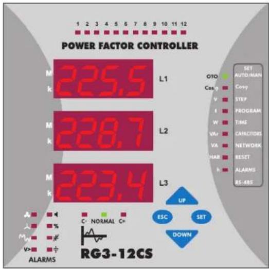
bar
POWER FACTOR CONTROLLER | Category | Value | |---|---| | M | 225.5 | | k | Not labeled (labeled 'L1') | | M | 228.7 | | k | Not labeled (labeled 'L2') | | M | 223.4 | | k | Not labeled (labeled 'L3') | | Parameter | Value | | :--- | :--- | | OTO | SET AUTO-MAN | | Cos. g | Conv | | V | STEP | | f | PROGRAM | | W | TIME | | VA+ | CAPACITORS | | VA | NETWORK | | HAB | RESET | | h | ALARMS RS-ABS | | Event | Condition | |---|---| | UP | Transition to RG3-12CS | | ESC | Transition to RG3-12CS | | SET | Transition to RG3-12CS | | DOWN | Transition to RG3-12CS | Legend: | Parameter | Color: Red = High, Blue = Low | |---|---| | ALARMS | Alarms (red), C- NORMAL C+ (green), C- NORMAL C+ (blue) | | Target | Target: AUTO-MAN | | Target: Auto-MAN | Target: AUTO-MAN | | Target: Cos. g | Conv | | Target: STEP | Step | | Target: Program | Program | | Target: Time | Time | | Target: VA+ | Capacitors | | Target: VA | Network | | Target: HAB | RESET | | Target: h | ALARMS RS-ABS | This is a schematic representation of the circuit or system. The diagram includes a schematic diagram with arrows pointing to the circuit elements.1.2.a Button Functions

In the observation mode, they are used for switching between observed parameters. In the programming mode, they are used for browsing the menu choices and changing the parameter values.

In the observation mode, it is used to switch between harmonic measurement mode and instant value measurement mode. In the programming mode, it is used to return to the previous menu or exit without saving any committed changes.

In the observation mode, it is used to show the harmonic value of the measured parameter. If it is pressed for 3 seconds, programming mode appears. In the programming mode, it is used to enter to a menu or confirm the data entry.
1.2.b Front Panel Functions


In order to enter to the menu, "SET" button must be pressed for 3 seconds. In the following sections, "enter the menu" means press the SET button for 3 seconds.
- L1 : Display for phase 1.
- L2 : Display for phase 2.
- L3 : Display for phase 3.
- Up Button : In the menu and measuring mode, is is used to move upwards. In the setup mode, it is used to increase the adjusted value.
- Esc Button : In the menu, it is used to return to the previous process or exit from a menu. In the measuring mode, it is used to leave the harmonic observation mode.
- Set Button : It is used to enter to the menu, to access a sub-menu and save the committed changes. In the measurement mode, it is used to monitor the harmonic values of voltage, current and power parameters.
- Down Button : In the menu and measuring mode, is is used to move downwards. In the setup mode, it is used to decrease the adjusted value.
- M LED : It indicates that the measured value is in mega units and the observed value is multiplied with 10^6 .
- k LED : It indicates that the measured value is in kilo units and the observed value is multiplied with 10^3 .
- 1,2,3,......,12 LEDs : These LEDs indicate the state of corresponding capacitor steps of the device. If a capacitor step is activated, the corresponding step LED is lit.
- SET Menu : Programmable menus which are set by pressing SET button for 3 seconds.
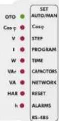
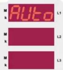
- OTO/MAN LED : This LED indicates if the operating mode is automatic or manual. If it is continuously on, the device is operating in Automatic Mode. If it blinks, the device is operating in Manual Mode. The color of this LED is green.
- Cosφ LED : If Cosφ LED is on in the menu, target Cosφ value can be set between Inductive 0,8 - Capacitive 0,8. If Cosφ LED is on in the measuring mode, Cosφ values of related phases are displayed.
-
STEP / V LED : If "STEP/V" LED is on in the menu, step number can be set in the menu. If "STEP/V" LED is on in the measuring mode, the phase voltages appear on their corresponding phase displays.
-
PROGRAM / I LED : If "PROGRAM/I" LED is on in the menu; the switching sequence can be set in the menu. If "PROGRAM/I" LED is on in the measuring mode, the phase currents appear on their corresponding phase displays.
- TIME / W LED : If "TIME/W" LED is on in the menu; discharge time, switch on delay time and switch off delay time can be adjusted in the menu. If "TIME/W" LED is on in the measuring mode, active power and total active power (Ind./Cap.) values of the phases are displayed on the corresponding displays.
- Capacitors/VAr LED: If "CAPACITORS/VAr" LED is on in the menu, the values and connection types(R, S,T, RST) of the capacitors can be set. If "CAPACITORS/VAr" LED is on in the measuring mode, reactive power and total reactive power (Ind./Cap.) values of the phases are displayed on the corresponding displays.
- NETWORK/VA LED : If "NETWORK/VA" LED is on in the menu; current transformer ratio(Ctr), voltage transformer ratio(Vtr) and calculation method can be set. If "NETWORK/VA" LED is on in the measuring mode, apparent power and total apparent power values of the phases are displayed on the corresponding phase displays.
- RESET / HAR LED : Press SET button for 3 seconds and enter the menu. Select the "RESET/HAR" LED to erase the energy values, reset the reactive energy ratios and alarms.
- ALARM / h LED : Press SET button for 3 seconds and enter the menu. Select "ALARM/h" LED to set the boundary values for alarms(overvoltage, reactive/active ratio, temperature and harmonics).
- RS-485 : In this menu; settings related to the RS-485 communication protocol(baudrate, address, parity) are set.
- C-LED : This LED indicates that RG3-12C/CS is waiting to switch off capacitor steps.
- NORMAL LED : This LED indicates that RG3-12C/CS will not switch any capacitor steps on or off.
- C+ LED : This LED indicates that RG3-12C/CS is waiting to switch on capacitor steps.
- : Incase of a failure, alarm relay switches on and alarm LED lights up.
- : In case of a connection failure, this LED lights up.
- % : If reactive energy ratios go beyond user-defined values, this LED lights up.
- : If voltage harmonic ratios go beyond user-defined values, this LED lights up.
- ¥ : When target Cosφ value is not reached even though all of the capacitor steps are switched on(insufficient step power for target compensation), this LED lights up.
- ≠ : If there isn't a capacitor connected to a step, capacitor step failure LED lights up.
- V> : If the voltage value exceeds the user-defined overvoltage, this LEDC lights up.
- : 10 seconds after the measured temperature value exceeds the user-defined fan operating value, fan LED lights up.
1.3 Rear Panel
CONNECTION DIAGRAM

* Current value of 3-Phase fuses, which are connected to protect the capacitors, must be chosen according to the nominal current value of capacitors which are given by the manufacturer.
**Optional.
Warnings :
a) First, connection type of auxiliary supply, voltage measurement and current measurement input must be 3 phase-neutral. The device will not operate properly if these connections are not done.
b) After the device is energized, it finds connection errors and corrects automatically as the first operation. Phase current should not be equal to zero in order to let the device to detect the connection error. Device detects the connection error according to Active Power direction. Device switches "ON" and "OFF" the 1st step's 3-phase capacitor during the correction of connection errors (Phase sequence error and polarity error of Current Transformer). Device may not correct the connection errors if there are too many instant variations for loads and nonlinear loads (Such as Thyristor or triac controlled frequency inverter, UPS etc.). In this case, user should disconnect the device and restart it to make the same operation. This feature also can also be operated with "turning ON" the "Auto SET" function in "Auto" menu. In this case device corrects the errors and then calculates the capacitor values.
c) After connection errors are corrected; capacitor steps are calculated with turning "ON" the "Auto Setup" function in "Auto" menu (Refer to "Automatic Capacitor Recognition" menu). A 3-phase capacitor has to be connected to 1st step of the device. All steps are measured separately if the program-10 (PS-10) is selected in "Program" menu. In this program (PS-10); single or 3-Phase capacitors can be connected according to requirements of the system in any order. If you let the device calculate the step power values in the previous step, you can skip this part. If one of the other programs is chosen, device measures the 1st steps power value and then calculates the other steps values according to 1st steps value. Device calculates the capacitor values which will be switched "ON" according to selected program and switches "ON" or "OFF" the necessary steps.
d) Connection of a circuit breaker or an automatic fuse is highly recommended between the network and RG3-12C/CS. This circuit breaker must be marked in order to separate them from other breakers.
e) All fuses which are used must be FF type and the current values of the fuses must be 2A or 3A and 6A (Refer to Connection Diagram).
f) The connection to the generator input of the device must be done in a way that the energy comes to the system after the generator connection to the network has been established. Otherwise, the device will be switched to the generator operation for any generator starts including the ones for maintaining purposes.
g) In order make a correct measurement, J type (Fe/Cu-Ni) thermocouple must be connected to "TEMP" terminal.
- For proper operation; 3-Phase, neutral, voltage and current terminals must be connected as shown in the connection diagram. Device does not work properly without 3-phase connection.
● After the connection of the current and voltage lines, connect the capacitors to the device. The most important point is connecting a 3-phase capacitor to the first step. Remaining single phase and 3-phase capacitors can be connected to the other steps in any order and power values.
● After the connection of capacitor steps; J-Type 0-400 V thermocouple must be connected if temperature measurement function will be used (Temperature measurement feature is optional).
● Lastly, computer communication connection must be done. - Do not energise the device before verifying the connections.
● Always connect a 3-phase capacitor to the 1st step.
2.1 Commissioning of RG3-12C/CS
- When RG3-12C/CS is energised for the first time, if the power value of any phase is negative, it switches on&off the first capacitor step automatically to recognize the connection error and records the connections.
● Later, automatic setup (Refer to page 6 - Automatic setup) is selected from the menu in order to recognise the connections and connected capacitor steps automatically.
● After automatic recognition, RG3-12C/CS checks all capacitor step values. If variable loads exist in the system, these variable loads must be disconnected first and then automatic setup process must be done. Otherwise, power factor controller may not measure capacitor step powers correctly. Capacitor step powers and connection types also can be entered to the power factor controller manually.
(Refer to page 10 - Setting of the capacitor's connection and power values)
● After recognising the capacitor step powers, target Cosφ value is set in order to start the compensation. Factory set value for target Cosφ is ind. 1.000 and Cosφ2 is ind. 0.900
Note: PFC decreases the switching on/off time to 3 seconds in Automatic Setup mode but discharge time is not changed. After the automatic setup process, set values become valid.
2.2 Capacitor Sequence Setting
After the device is energised, it finds connection errors and corrects them automatically. Power values of the capacitor steps are measured automatically according to program selection. If PS-10 program is selected, power values of all capacitor steps are measured (Refer to Program Section). If any other program is selected, device measures first capacitor step value and then calculates other capacitor steps according to the selected program. For this reason, a 3-phase capacitor must be connected to the first step. Single phase and/or 3-phase capacitors can be connected in any order to the other steps. After the device calculates and saves the capacitor values, it will switch them on and off when needed.
3. SETTINGS
3.1 Manual Operation Mode, Automatic Capacitor Recognition Mode and Automatic Connection Control Mode
3.1.a Manuel Operation Mode Setting
RG3-12C/CS has two operating modes which are automatic and manual. The operation mode is chosen by selecting the "Auto Operati" option as on(automatic mode) or off(manual mode). Manual mode is used for test purposes. In this mode, capacitor steps are switched on&off to test relay outputs. In manual mode, capacitor steps are switched on with "SET" button and switched off with "ESC" button. The conditions of the steps can be monitored from the 12 step LEDs on the front panel. C+ LED lights up when a step is switching on and C-LED lights up when a step is switching off. Factory set values for switching on (t-on) and switching off (t-of) time are 10 sec. These values can be changed by the "dELy" menu (Refer to Switching on&off Time for Capacitor Steps and Discharge Time Settings). In manual mode; step numbers, which will be switched on&off, can be programmed in "StEP" menu (Refer to Step Number Setting). Even if manual mode is selected, device switches to automatic mode after 5 minutes continues to operate in this mode.
When automatic mode is selected, AUTO/MAN LED lights up continuously.
When manual mode is selected, AUTO/MAN LED blinks.
Warning: Device warns user by blinking (short ON, long OFF) the LED of the capacitor steps which will be switched on. Also device warns user by blinking (long ON, short OFF) the LED of the capacitor steps which will be switched off.
Numerical values of the parameters are set via buttons in the display. The blinking digit indicates which digit will be set. Numerical value of the related digit is increased or decreased via "UP" or "DOWN" button. To set the next digit, "SET" button is used. To go back to the previous digit, "ESC" button is used.
3 sec.
Press the "SET" button for 3 sec. in order to enter to the menu.
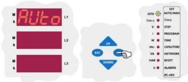
Press "SET" button to set the parameters in "Auto" menu option.

The first setting in this menu is the operation mode(Operati). The operation mode of the device is selected according to this options on or off selection. Press "SET" button to change this setting.
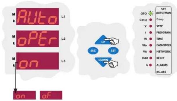
Press "UP" or "DOWN" button. To select the automatic operating mode, choose "on" with "UP" or "DOWN" buttons and press "SET" button. To select the manual operating mode, choose "oF" with "UP" or "DOWN" buttons and press "SET" button.
When the device is energised for the first time, it checks for connection errors. If there is a faulty connection, it corrects this fault in itself. In order for the device to correct a connection fault, 3-phase voltage and current connections of the device must be done.
NOTE: If there are other loads than compensation connected to the system, the device may not find the connection at the first try and may need several tries. However, if the device is unable to complete the automatic connection process step calculation process shouldn't be done.
In order for the calculated capacitor powers to be accurate, the current and voltage transformer ratios have to be entered correctly before the automatic capacitor recognition process. If these ratios are not entered by the user, they will be set as "1" by the device and the capacitor step powers will be calculated according to these values(Refer to page 12-CT and VT Ratio Settings).
After any connection faults are corrected by the device; if "Auto Setup" option is set as "on", the device calculates the capacitor step powers according to the selected program. If 10th program(P-10) is selected, all of the capacitor step powers are measured separately. If any other program is selected, the device measures only the first capacitor step power and then calculates the other step powers according to the selected program(Refer to page 7-Step Number Setting).
NOTE: If the option "on" is selected in the automatic setup menu, the automatic capacitor recognition will start without exiting the menu.
The step powers which are calculated after this process must always be checked.


In Auto Operati menu, choose "Auto Setup" menu by pressing the "UP" button.


The 2nd setting in this menu is the Auto Setup setting. The automatic setup will or will not start according the options "on" or "off" selection. To change this setting, press the SET button.


Select "on" or "of" using the "UP" and "DOWN" buttons (Select "on" for automatic capacitor recognition).
3.1.c Automatic Connection Recognition Mode Setting
This option is used for activating or deactivating the connection recognition mode when the device is energised. It is activated as factory default. In applications with a generator, the voltage and current information may not arrive to the device properly depending on the transfer panels design and delay when the system is switched from generator to the network power. When this transition occurs, the device may find a connection fault. Therefore, it is recommended to turn this option off after the setup is completed.


Select the Auto Setup option in the Auto Operati menu with "DOWN" button.


Connection correction is activated or deactivated depending on the "on" or "off" position of the Auto connection option. To change this setting press the "SET" button.


When Auto connection is "on", the device controls its connection automatically at start-up and corrects any existing measurement input errors. If this option is "of", automatic connection correction is deactivated. Using "UP" ve "DOWN" buttons, select "on" or "of".
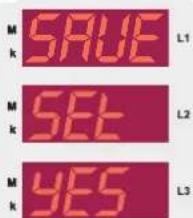

If you want to leave the setup menu without making any other changes, press the "ESC" button until "SAVE SET yES" shows on the screen. If you want to save the changes, press the "SET" button. If not, press the "ESC" button.
3.2 Target Cosφ and Target Cosφ2 Value Setting
The device has two target Cosφ values as Cosφ ve Cosφ2.
If there is a voltage between 110-250 VAC present on the generator inputs of the device, the target "Cosφ" set on the device is deactivated and target "Cosφ2" is activated. Then the device starts the compensation according to target Cosφ2. This operation mode continues until the voltage on the generator input is disappeared.
Target Cosφ ve Cosφ2 values may be adjusted between "0,800 ... -0,800" by the user. Negatif values represent Capacitive region and positive values represent Inductive region. RG3-12C/CS tries to match the systems Cosφ to the user defined value. If the need for compensation of a phase is lower than 0,625 times of the capacitor which is connected to that phase, the device doesn't activate or deactivate any steps and stays at NORMAL status. If there aren't any connected capacitors on that phase, the device operates according to one-third(the power for that phase) of the 3-phase capacitor with the lowest power value.
3.2.a Inductive / Capacitive Cosφ and Cosφ2 Setting
Target Cosφ and Cosφ2 values may be entered between "0,800 ... -0,800"
Negative values represent Capacitive Region, positive values represent Inductive
Region

Press the "SET" button for 3 sec. in order to enter to the menu.


Using the "DOWN/UP" buttons, find the Target Cosφ (COS or COS2) menu option.


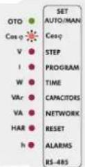
Press the "SET" button to enter the Target Cosφ menu.


Using the "UP/DOWN" buttons, enter a Cosφ value between -0,800 ... 0,800 and press the "SET" button.
Using the "UP/DOWN" buttons, enter to another menu option which you wish to change. If you are not going to change any more settings, press the "ESC" button.


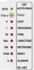
If you want to leave the setup menu without making any other changes, press the "ESC" button until "SAVE SET yES" shows on the screen. If you want to save the changes, press the "SET" button. If not, press the "ESC" button.
3.3 Last Capacitor Step Number Setting
The last capacitor step number is entered between 1-12 for RG3-12C/CS in this menu. For example, if this number is entered as 8, only the steps 1 through 8 will be operated by the device. After this setting is changed, the device must be de-energised and re-energised. If not, the active steps which aren't selected may stay activated.
NOT: When program 10(PS-10) is selected, it is better if the last capacitor step number is set as 12. When program 10 is selected, the activation and deactivation of the steps without a capacitor connected to them is not an issue because with program 10, the connection for these steps can be set as "oFF". The last capacitor step number should be used with the switching sequences other than the 10th.

Press "SET" button for 3 sec. in order to enter to the menu.


Using the "UP/DOWN" buttons, find the step number(StEP) menu option. When the step number setting menu is selected, the STEP LED will turn on.


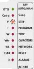
Press the "SET" button to enter the last capacitor step number.


Using the "UP/DOWN" buttons, enter a last capacitor step number between 1-12 and press the "SET" button.
Using the "UP/DOWN" buttons, enter to another menu option which you wish to change. If you are not going to change any more settings, press the "ESC" button.


If you want to leave the setup menu without making any other changes, press the "ESC" button until "SAVE SET yES" shows on the screen. If you want to save the changes, press the "SET" button. If not, press the "ESC" button.
3.4 Selection of Proper Switching Sequence
RG312C/CS has 10 different program modes which determines the power ratio sequence of the capacitor steps. The switching programs are given in the table.
If the step sequence is selected as in program 02(PS-02), many identical connection components must be used. When a step sequence between the 3rd and the 8th one is selected, less identical connection components will be used. By selecting the 9th connection sequence, different group powers can be achieved. In this sequence connection, the rating of each capacitor step value may exceed that of the first by a maximum amount equal to the preceding capacitor steps value. By using this setting, less capacitors will be used. When the 10th connection sequence is selected, RG3-12C/CS will calculate the capacitor step power values automatically. RG3-12C/CS counts swithing on&off times of all capacitor steps and so only the most necessary step is switched on. Thus, maximum service life time of the system is ensured.
Note: In the 10th program(PS-10), power values and connection types(except the first step) of the single phase capacitor steps(r, s, t, rst, oFF) can be set by user. In Auto setup mode power values of all capacitor steps are measured and connection types of the capacitor steps are detected by the device. In all the connection sequences except the 10th one, only the 1st capacitor step power can be set. All the other capacitor step values are calculated according to the 1st capacitor steps power value.
Set the program option suitable for your system in this menu.
3 sec.
Press the "SET" button for 3 sec. in order to enter to the


Using the "UP/DOWN" buttons, select the Program (Prog) menu. When program menu is displayed, program LED turns on.


Press the "SET" button to select the switching program.


Enter the desired program number between 01-10 and press the "SET" button.
Using the "UP/DOWN" buttons, enter to another menu option which you wish to change. If you are not going to change any more settings, press the "ESC" button.

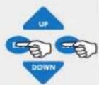

If you want to leave the setup menu without making any other changes, press the "ESC" button until "SAVE SET yES" shows on the screen. If you want to save the changes, press the "SET" button. If not, press the "ESC" button.
| PROGRAM SEQUENCE | |
| 01 | linear |
| 02 | 1.1.1.1...... |
| 03 | 1.1.2.2...... |
| 04 | 1.2.2.2...... |
| 05 | 1.2.3.3...... |
| 06 | 1.2.4.4...... |
| 07 | 1.1.2.4...... |
| 08 | 1.2.3.4...... |
| 09 | 1.2.4.8...... |
| *10 | Capacitor step values are calculated automatically. |
* Recommended switching program.
3.5 Switching On&Off and Discharge Time Settings
In order to decrease harmful effects of instant reactive power loads to the relays and capacitors, delay time (in terms of seconds) for capacitor steps is entered in this menu.
Note: t-on and t-of time periods must be set according to your systems requirements. If t-on time is set very long, relay can not switch on until the end of this time period and so target compensation ratios may not be achieved. If t-on time is set too short, capacitor steps switch on&off frequently in case of fast load variations and this will shorten the life time of contactors and capacitors. For this reason, it is very important to set these time periods according to your system's requirement.
3.5.a Switch-On Delay Time Setting
Switch-on delay time must be set according to system requirement in order to achieve compensation targets and also to provide long life time for contactors and capacitors.

Press "SET" button for 3 sec. in order to enter to the menu.


Using the "UP/DOWN" buttons, select the delay time menu(dELy). When delay time menu is displayed, time LED turns on.
Press the "SET" button to enter delay time settings menu(dELy).
3.5.b Switch-Off Delay Time Setting
Switch-off delay time must be set according to system requirement in order to achieve compensation targets and also to provide long life time for contactors and capacitors.

Using the "UP/DOWN" buttons, select the switch-off delay time (dELy t-oF) menu.
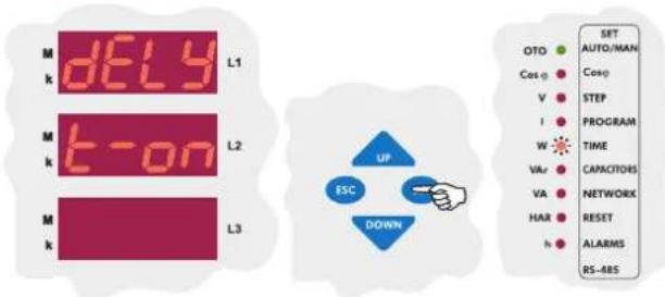
The first setting in this menu is the switch on delay time setting(t-on). Press the "SET" button to change this time value.
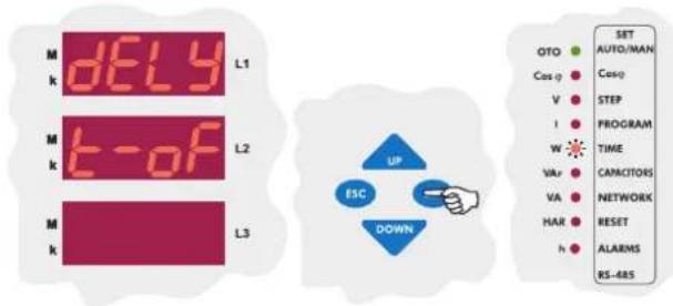
Press the "SET" button to change this time value.

Enter a value between 1-1800 seconds and then press "SET" button. Using the "UP/DOWN" buttons, enter to another menu option which you wish to change. If you are not going to change any more settings, press the "ESC" button.

Enter a value between 1-1800 seconds and then press "SET" button. Using the "UP/DOWN" buttons, enter to another menu option which you wish to change. If you are not going to change any more settings, press the "ESC" button.

If you want to leave the setup menu without making any other changes, press the "ESC" button until "SAVE SET yES" shows on the screen. If you want to save the changes, press the "SET" button. If not, press the "ESC" button.
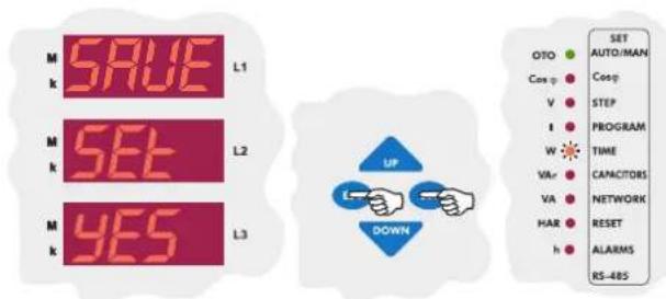
If you want to leave the setup menu without making any other changes, press the "ESC" button until "SAVE SET yES" shows on the screen. If you want to save the changes, press the "SET" button. If not, press the "ESC" button.
Discharge time must be set according to determined time periods by the capacitor suppliers. If discharge coil or contactors, which have discharge coils, are used, discharge time can be shorten according to do instructions defined by the suppliers.

Using the "UP/DOWN" buttons, select the discharge time menu (dELy t-rC).
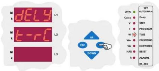
Press the "SET" button to set discharge time.

Enter a value between 1-1800 seconds and then press "SET" button. Using the "UP/DOWN" buttons, enter to another menu option which you wish to change. If you are not going to change any more settings, press the "ESC" button.
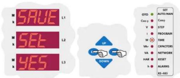
If you want to leave the setup menu without making any other changes, press the "ESC" button until "SAVE SET YES" shows on the screen. If you want to save the changes, press the "SET" button. If not, press the "ESC" button.
3.6 Power Value and Connection Type Settings for Capacitors
In this menu, power values and connection types of all capacitor steps can be set.
There are 5 different connection types for capacitors which are "R, S, T, RST and off". Also capacitor step measurement for power values can be set between 0,020-2,000 kVAr. If a capacitor step is set as "off", there is no need to set any power value.
Note : For the first capacitor step. There isn't a connection type setting. "RST" connection type always must be selected because first capacitor step is used to detect correct connection.
Note : If the 10th program is selected, capacitor powers can be set separately for each capacitor step. However; if any program except PS-10 is selected, only first capacitor steps power value (C-01) can be set manually. Capacitor powers for other steps are calculated in 3-phase according to the selected program.
3.6.a First Capacitor Step Setting
First capacitor step is used to find connection. Therefore, a 3-phase capacitor must be connected to the first step. For this reason, it isn't possible to set the connection setting for first capacitor step and it is always selected "RST" type.
When setup parameter is selected as "on" in Auto menu, if any program except PS-10 is selected, power value of the first capacitor step is measured and other steps power values are calculated according to selected program. When setup parameter is selected as "of", power values of all capacitor steps (including first capacitor step) can be set manually.
Note : When setup parameter is selected as "on" in Auto menu, after completing the measurement of capacitor powers according to the selected program, RG3-12C/CS continues to work in "setup:of" mode.

Press the "SET" button for 3 sec. in order to enter to the menu.

Using the "UP/DOWN" buttons, select capacitor (CAP) menu. When capacitor menu is displayed, capacitor (C/VAr) LED turns on.

Press the "SET" button to enter capacitor settings menu.
Press the "SET" button to enter to the first capacitor step setting menu(C-01) which is the first menu under the capacitor menu option.

First capacitor step is used to find connection. Therefore, a 3-phase capacitor must be connected to the first step. For this reason, it isn't possible to set the connection setting for first capacitor step and it is always selected "RST" type and it can not be changed. Press the "SET" button to set power value of the first capacitor step.

Enter the power value of the first capacitor step and then press the "SET" button. If you do not want to set another parameter, press the "ESC" button.
Note : If the 10th program is selected, capacitor powers can be set separately for each capacitor step. However; if any program except PS-10 is selected, only first capacitor steps power value (C-01) can be set manually. Capacitor powers for other steps are calculated in 3-phase according to the selected program.
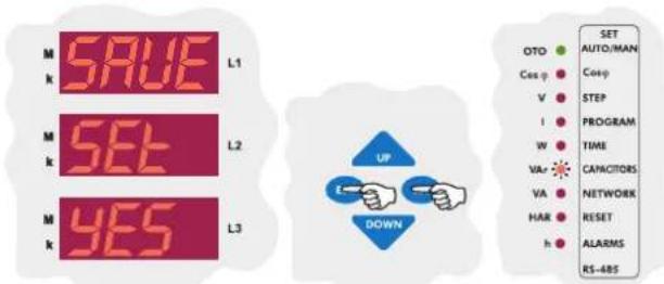
If you want to leave the setup menu without making any other changes, press the "ESC" button until "SAVE SET YES" shows on the screen. If you want to save the changes, press the "SET" button. If not, press the "ESC" button.
3.6.b Second Capacitor Step Setting
When PS-10 (Program 10) is selected, connection type and capacitor power value settings of all capacitor steps from the 2nd to the 12th can be set. When a program expect PS-10 is selected, only first capacitor steps setting can be changed and other steps can not be set.
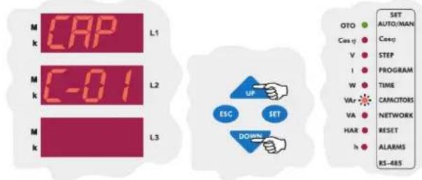
Using the "UP/DOWN" buttons, find the second capacitor step setting menu(C-02).

The first setting in the second capacitor step menu is the connection type. Press the "SET" button to select connection type.
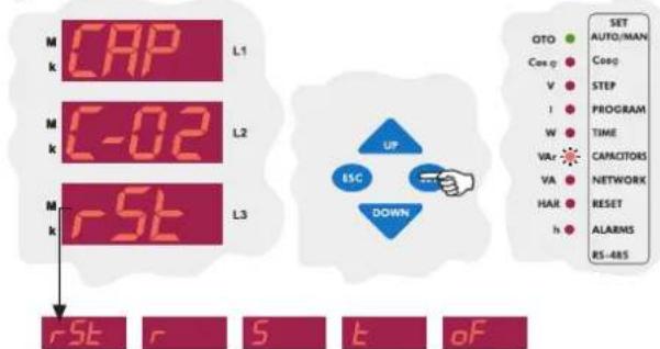
Using the "UP/DOWN" buttons, second capacitor steps connection type can be set manually as connected to the "r", "S", "t" or "rSt" phase/phases. If this parameter is selected as "oFF", capacitor step which is connected to the second step will be disabled.
Note : After automatic calculation of the capacitors, if "oFF" is displayed in any step, it means that related capacitor could not be calculated, is defected or there is no connected capacitors in the related step. Press the "SET" button to set second capacitor steps power value.

Enter the power value of the second capacitor step and then press the "SET" button. If you do not want to set another parameter, press the "ESC" button.
Enter the power value of the second capacitor step and then press the "SET" button. If you do not want to set another parameter, press the "ESC" button.

If you want to leave the setup menu without making any other changes, press the "ESC" button until "SAVE SET YES" shows on the screen. If you want to save the changes, press the "SET" button. If not, press the "ESC" button.

CAP C-03
In this menu, capacitor setting for third step are done.
CAP C-04
In this menu, capacitor setting for fourth step are done.
CAP C-05
In this menu, capacitor setting for fifth step are done.
CAP C-06
In this menu, capacitor setting for sixth step are done.
CAP C-07
In this menu, capacitor setting for seventh step are done.
CAP C-08
In this menu, capacitor setting for eighth step are done.
CAP C-09
In this menu, capacitor setting for ninth step are done.
CAP C-10
In this menu, capacitor setting for tenth step are done.
CAP C-11
In this menu, capacitor setting for eleventh step are done.
CAP C-12
In this menu, capacitor setting for twelveth step are done.
- Above capacitor steps' settings are done just like second capacitor step setting (C-02).
3.7 Current and Voltage Transformer Ratio Settings
To obtain accurate power values when calculating the capacitor step powers, current and voltage transformer ratios must be entered correctly. If these ratios are entered incorrectly, the calculated capacitor step powers will be incorrect. When these ratios aren't entered, the device will set these ratios as "1" and capacitor step powers will be calculated according to this setting.
Current and voltage transformer ratios can be set separately.
3.7.a Current Transformer Ratio Setting
In this menu, current transformer ratio can be set between 1-2000.
For example: For a 150/5 current transformer, CT ratio must be set as 30.
Note : Be aware that this value is entered as a ratio, not CT primary or secondary value.
3 sec.
Press the "SET" button for 3 sec. in order to enter to the menu.

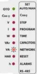
Using the "UP/DOWN" buttons, find current and voltage transformer ratio menu (trF). When this menu is selected, Transformer (VA/TRF) LED turns on.

flowchart
graph TD
    A["trf"] --> B["L1"]
    C["M"] --> D["L2"]
    E["M"] --> F["L3"]
    style A fill:#ff0000,stroke:#333
    style B fill:#ff0000,stroke:#333
    style C fill:#ff0000,stroke:#333
    style D fill:#ff0000,stroke:#333
    style E fill:#ff0000,stroke:#333
    style F fill:#ff0000,stroke:#333
    subgraph UP
        G["ESC"] --> H["DOWN"]
    end
    I["SET AUTO/MAN"] --> J["OTO"]
    J --> K["Cosφ"]
    K --> L["V"]
    L --> M["I"]
    M --> N["W"]
    N --> O["VAR"]
    O --> P["VA"]
    P --> Q["HAR"]
    Q --> R["h"]
    R --> S["RESET"]
    S --> T["ALARMS"]
    T --> U["RS-485"]
Press the "SET" button to enter to the CT and VT ratio setting menu.
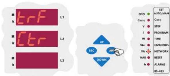
The first setting in the CT and VT ratio menu is the CT ratio menu. Press the "SET" button to set CT ratio.
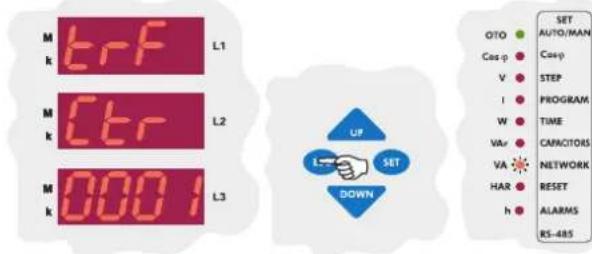
Enter CT ratio between 1-2000 and press the "SET" button. If you do not want to set another parameter, press the "ESC" button.

If you want to leave the setup menu without making any other changes, press the "ESC" button until "SAVE SET YES" shows on the screen. If you want to save the changes, press the "SET" button. If not, press the "ESC" button.
In this menu, voltage transformer ratio can be set between 1-2000. For example: For a 34,5 kV / 100 V transformer, VT ratio must be set as 345.
Note : Be aware that this value is entered as a ratio, not VT primary or secondary value.

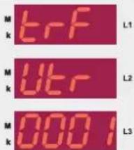
Using the "UP/DOWN" buttons, enter the voltage transformer ratio (Vtr) menu which is the second menu in CT and VT ratio settings.
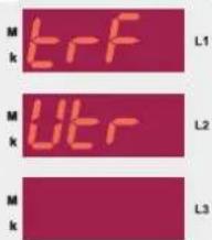

Press the "SET" button to set VT ratio.


Enter VT ratio between 1-2000 and press the "SET" button. If you are going to change another setting, enter to that setting menu using the "UP/DOWN" buttons. If you do not want to set another parameter, press the "ESC" button.


If you want to leave the setup menu without making any other changes, press the "ESC" button until "SAVE SET YES" shows on the screen. If you want to save the changes, press the "SET" button. If not, press the "ESC" button.
3.7.c Reactive Energy Calculation Method Setting
Three different methods exist for reactive energy calculation in RG3-12C/CS. Brief informations about these methods are explained in below table. Related values which must be entered in the menu are also indicated in the table in order to select reactive power calculation methode for mechanical and digital energymeters.
| Mechanical Energymeter (Total sum of the three phases) | Digital Energymeter (Separately for each phase) | Reactive Energy (Q) | Description |
| 0 | 1 | Rotate the voltage vector by 90° and multiply with current | It is the most preferred reactive power calculation method. |
| 2 | 3 | V_n, I_n, (q_n) | Total value of the multiplication of V_n and I_n values up to 19 th harmonics. This calculation method is mostly preferred for network analysers. |
| 4 | 5 | ^2 - P^2 | Power Triangle Method : In this method; Q = S^2 - P^2 (Q : Reactive power, P : Active power, S : Apparent power)II is a less preferred method compared to the other methods. |


Using the "UP/DOWN" buttons, find the reactive energy calculation method menu(CALC).

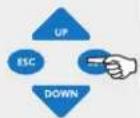

Press the "SET" button to select the calculation method.


In order to select reactive energy calculation method (for mechanical and digital energymeter), enter a value between 0-5 and press the "SET" button. If you are going to change another setting, enter to that setting menu using the "UP/DOWN" buttons. If you do not want to set another parameter, press the "ESC" button.


If you want to leave the setup menu without making any other changes, press the "ESC" button until "SAVE SET yES" shows on the screen. If you want to save the changes, press the "SET" button. If not, press the "ESC" button.
In this menu; alarms and ratios(reactive/active ratios) are reset.
3.8.a Alarm Reset Setting
The alarms which occur when the device operates are reset in this menu. To reset the alarms, "yES" option must be selected.
Note : When an alarm occurs, the alarm relay switches on and the related alarms LED turns on and the alarm code is displayed. Even if alarm conditions disappear, the alarm relay will stay switched on. By using the reset menu, alarms are reset and alarm relay is switched off. If alarm conditions still exist, even if alarms are reset in the "reset" menu, alarm relay switches on again. If alarm conditions disappeared, alarm relay continues to its normal operation.
3 sec.
SIT
Press the "SET" button for 3 sec. in order to enter to the menu.

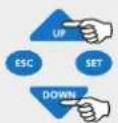

Using the "UP/DOWN" buttons, find the reset menu option(rESEt). When reset menu is selected, reset LED turns on.
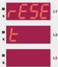


Press the "SET" button to enter reset(rESEt) setting options.
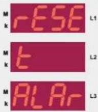


Press the "SET" button to set the alarm(ALAr) setting which is the first setting in the reset(rESEt) menu.


Using the "UP/DOWN" buttons, select "yES" to delete alarm values or "no" to cancel the delete process and then press "SET" button.
3.8.b Reactive/Active Ratio Reset Setting
Reactive/active ratio, which is calculated by the device, is reset in this menu.
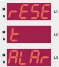
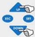

Using the "UP/DOWN" buttons, find "reactive/active ratio reset" menu(rAtE) which is the second setting in the reset(rESEt) menu.
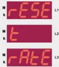


Press the "SET" button to enter the reactive/active ratio reset settings.


Using the "UP/DOWN" buttons, select "yES" to delete reactive/active ratio or "no" to cancel the delete process and then press "SET" button.


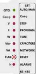
If you want to leave the setup menu without making any other changes, press the "ESC" button until "SAVE SET yES" shows on the screen. If you want to save the changes, press the "SET" button. If not, press the "ESC" button.
In this menu, alarm values for overvoltage, reactive/active ratio, *temperature and THD can be set separately.
Device has 2 relay outputs in addition to capacitor step relays which are alarm relay and *fan relay.
If any of the above mentioned alarm conditions (except temperature) occurs, alarm relay switches on and the related error LED and alarm LED (◄) light(Refer to "errors" section for details).
Also, related error code is displayed on the display(Refer to page 30 for alarm codes).
* Optional
3.9.a Overvoltage Alarm Setting
In this menu, the limit value for the overvoltage alarm is set. This value is used for all three phases. If any phase value exceeds the set value and the alarm condition still exists even after the entered delay time is over, alarm relay switches on and the overvoltage LED(V>) turns on.
3.9.a.a Overvoltage Setting
In this menu, overvoltage value is set between 0-300 V (for Vtr=1). If this value is set as "0", this function is disabled.
3 sec.
Press the "SET" button for 3 sec. in order to enter to the menu.

Using the "UP/DOWN" buttons, find Alarm(ALr) menu. When Alarm menu is selected, alarm LED turns on.

The first setting in the alarm menu(ALr) is the voltage(UoLt). Press the "SET" button to enter the overvoltage settings menu.

Overvoltage value (SP-H), delay time (dELy) and overvoltage step (StEP) parameters can be set in this menu. In order to set these parameters, press the "SET" button.
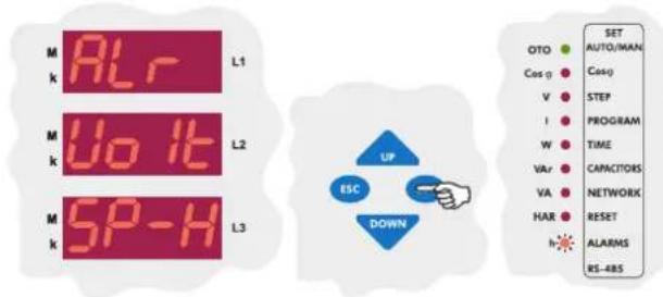
Press the "SET" button to set the overvoltage value(SP-H).

Enter the overvoltage value between 0-300 V. If you are going to change another setting, return to the menu by pressing the "SET" button. If you do not want to set another parameter, press the "ESC" button.
Note : If over voltage value is set as "0", this function is disabled.

If you want to leave the setup menu without making any other changes, press the "ESC" button until "SAVE SET YES" shows on the screen. If you want to save the changes, press the "SET" button. If not, press the "ESC" button.
3.9.a.b Overvoltage Delay Time Setting
If one or more of measured phase voltage values exceed preset voltage value, an alarm occurs at the end of the adjusted delay time. Delay time can be set between 0-999.9 seconds.
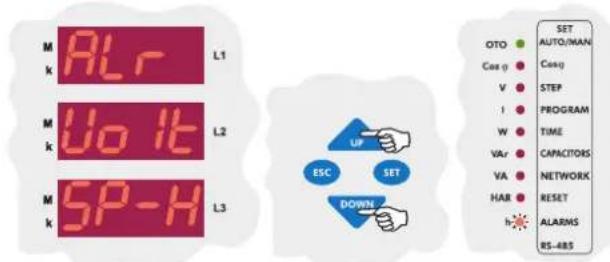
Press the "DOWN" button to select the over voltage delay time (dELy) menu.
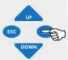
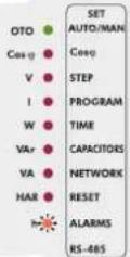
The second setting in the voltage menu(UoLt) is the overvoltage delay time(dELy). Press the "SET" button to enter the overvoltage delay time setting menu.

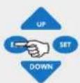
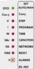
Enter the over voltage delay time between 0-999.9 seconds. If you are going to change another setting, return to the menu by pressing the "SET" button. If you do not want to set another parameter, press the "ESC" button.


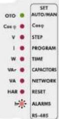
If you want to leave the setup menu without making any other changes, press the "ESC" button until "SAVE SET yES" shows on the screen. If you want to save the changes, press the "SET" button. If not, press the "ESC" button.
3.9.a.c Switch On or Switch Off Setting of Capacitor Steps for Overvoltage Alarm Setting
In order to protect the capacitors from overvoltage, when an overvoltage alarm occurs, capacitor steps' switch on or switch off settings are done in this menu.
If "on" is selected: When overvoltage error occurs, capacitor steps stay switched on.
If "off" is selected: When overvoltage error occurs, capacitor steps stay switched off.


Press the "DOWN" button in order to switch from overvoltage menu to the overvoltage step menu(StEP).

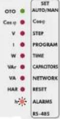
The third setting in the voltage menu(UoLt) is the overvoltage step setting(StEP). Press the "SET" button to enter the overvoltage step setting menu.
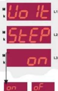

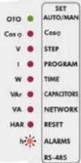
Using the "UP/DOWN" buttons, select "on" or "of" option and press the "SET" button. If you are going to change another setting, return to the menu by pressing the "SET" button. If you do not want to set another parameter, press the "ESC" button.


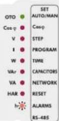
If you want to leave the setup menu without making any other changes, press the "ESC" button until "SAVE SET yES" shows on the screen. If you want to save the changes, press the "SET" button. If not, press the "ESC" button.
3.9.b Reactive / Active Ratio Setting
If reactive/active energy ratio exceeds the preset value, an alarm occurs. This ratio can be set for inductive/active and capacitive/active separately between 0-99.9 %. If this value is set as "0", this function is disabled.
3.9.b.a Capacitive Ratio Setting
In order to provide accurate compensation, the upper limit value of capacitive/active ratio is entered in this menu. This value can be set between 0-99.9 %. If the capacitive/active ratio of the network exceeds the preset value, an alarm occurs. If this value is set as "0", this function is disabled.
3 sec.
Press the "SET" button for 3 sec. in order to enter to the menu.

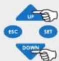
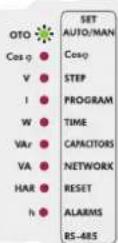
Using the "UP/DOWN" buttons, find Alarm (Alr) menu. When "Alarm" menu is selected, alarm LED turns on.
Using the "UP/DOWN" buttons, find reactive/active ratio (rAtE) menu.

The second setting in the alarm menu(ALr) is the reactive/active energy ratio menu(rAtE). From this menu, the upper limit value of the capacitive/active and inductive/active ratios can be set. Press the "SET" button to set these values.

Press the "SET" button to set the capacitive/active ratio.

Enter the capacitive/active ratio between 0-99.9 % and press the "SET" button. If you are going to change another setting, return to the menu by pressing the "SET" button. If you do not want to set another parameter, press the "ESC" button.
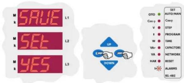
If you want to leave the setup menu without making any other changes, press the "ESC" button until "SAVE SET yES" shows on the screen. If you want to save the changes, press the "SET" button. If not, press the "ESC" button.
3.9.b.b Inductive Ratio Setting
In order to provide accurate compensation, the upper limit value of inductive/active ratio is entered in this menu. This value can be set between 0-99.9 %. If the inductive/active ratio of the network exceeds the preset value, an alarm occurs. If this value is set as "0", this function is disabled.
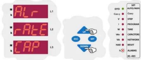
When "Air rAtE CAP" is displayed on the display, find "rAtE Ind" menu by using "UP/DOWN" buttons.

Press the "SET" button to set the inductive/active ratio.

Enter the inductive/active ratio between 0-99.9 % and press the "SET" button. If you are going to change another setting, return to the menu by pressing the "SET" button. If you do not want to set another parameter, press the "ESC" button.
If you want to leave the setup menu without making any other changes, press the "ESC" button until "SAVE SET YES" shows on the screen. If you want to save the changes, press the "SET" button. If not, press the "ESC" button.
3.9.c Temperature Alarm Settings
Note : Temperature measurement feature is optional for RG3-12CS. In order to protect the capacitors from overheating, upper (HEAt SP-H) and lower (HEAt SP-L) limits between "00.0-99.9 °C" and step protection (HEAt StEP) are all set in this menu. If the temperature exceeds the upper limit, which is programmed in the device, for 10 seconds; RG3-12C/CS gives an alarm signal (Erro r-10) and switches off or does nothing for the capacitor steps according to selected capacitor step setting(HEAt STEP). After the temperature stays under the lower limit value for 10 seconds, the alarm state disappears.
3.9.c.a Programming the Upper Limit of Temperature Alarm In this menu; the upper temperature limit, which activates the overheating protection, is programmed between "00.0-99.9 °C" (Refer to "Technical Features" section for measurable ranges).
3 sec. Press the "SET" button for 3 sec. in order to enter to the menu.

Using the "UP/DOWN" buttons, find the alarm menu(ALr). When "Alarm" menu is selected, alarm LED turns on.

Press the "SET" button to enter the alarm(ALr) settings.
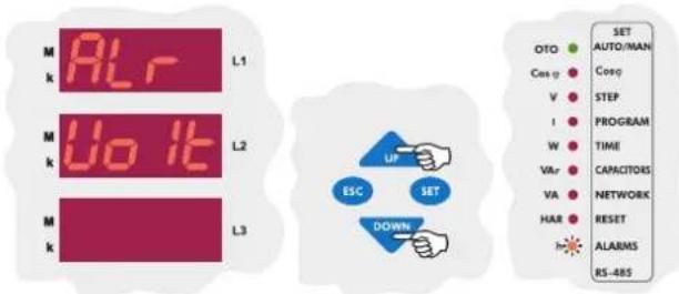
Using the "UP/DOWN" buttons, find temperature alarm menu(HEAT) which is the second setting in the alarm menu.

Press the "SET" button to select the "SP-H" menu in which the upper and lower limits for the temperature alarm to activate or deactivate the alarm relay is programmed.

Press the "SET" button to enter the upper limit of the temperature value(SP-H).

Enter a value between "00.0-99.9 °C" and press the "SET" button. If you are going to change another setting, return to the menu by pressing the "SET" button. If you do not want to set another parameter, press the "ESC" button.

If you want to leave the setup menu without making any other changes, press the "ESC" button until "SAVE SET YES" shows on the screen. If you want to save the changes, press the "SET" button. If not, press the "ESC" button.
3.9.c.b Programming the Lower Limit of Temperature Alarm
In this menu; the lower temperature limit, which deactivates the overheating protection, is programmed between "00.0-99.9 °C" (Refer to "Technical Features" section for measurable ranges).


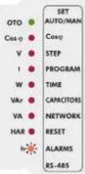
When "ALr HEAt SP-H" is displayed, find the lower temperature limit (SP-L) by using the "UP/DOWN" buttons.

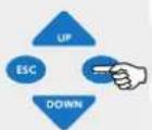
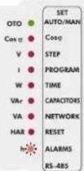
Press the "SET" button to set the lower temperature limit(SP-L).


Enter a value between "00.0-99.9 °C" and press the "SET" button. If you are going to change another setting, return to the menu by pressing the "SET" button. If you do not want to set another parameter, press the "ESC" button.


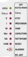
If you want to leave the setup menu without making any other changes, press the "ESC" button until "SAVE SET yES" shows on the screen. If you want to save the changes, press the "SET" button. If not, press the "ESC" button.
3.9.c.c Programming the Switching Off of the Capacitor Steps in Case of Overheating
In order to protect the capacitors from overheating, they can be set to switch off in case of overheating in this menu.
If "on" option is selected, when an overheating alarm occurs, capacitor steps stay switched on.
If "of" option is selected, when an overheating alarm occurs, capacitor steps switch off.
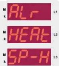
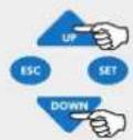

When "ALr HEAt SP-H" is displayed, find the step menu(StEP) by using the "UP/DOWN" buttons.


Press the "SET" button for programming the switching off of the capacitor steps in case of overheating.
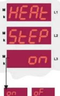


Using the "UP/DOWN" buttons, select "on" or "oF" option and press the "SET" button. If you are going to change another setting, return to the menu by pressing the "SET" button. If you do not want to set another parameter, press the "ESC" button.
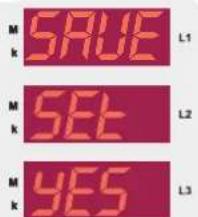

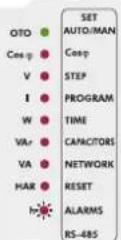
If you want to leave the setup menu without making any other changes, press the "ESC" button until "SAVE SET YES" shows on the screen. If you want to save the changes, press the "SET" button. If not, press the "ESC" button.
If total harmonic value of measured voltages exceeds the value which is entered from this menu and does not return to normal level during the entered delay time(dELy), alarm relay switches on and harmonic LED( ^Mw ) turns on.
3.9.d.a Overvoltage Harmonic Setting
The upper limit for the overvoltage harmonic value to set the harmonic alarm is set in this menu.
3 sec. Press the "SET" button for 3 sec. in order to enter to the menu.
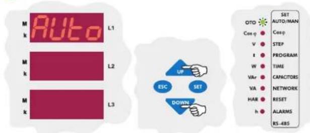
Using the "UP/DOWN" buttons, find the alarm menu(ALr). When alarm menu is selected, alarm LED turns on.
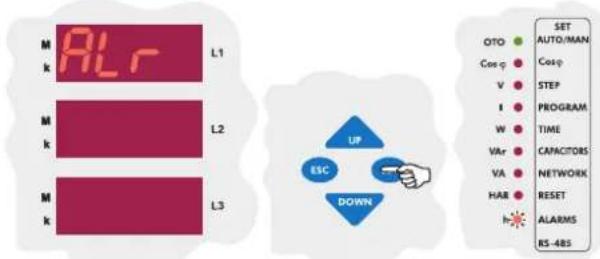
Press the "SET" button to enter the alarm(ALr) settings.

Using the "UP/DOWN" buttons, find over voltage harmonic menu(tHd) which is the fourth setting in the alarm menu.

In this menu, over voltage harmonic value(tHdV), delay time(dELy) and switching off of the capacitor steps(StEP) parameters are set. In order to set these parameters, press the "SET" button.

Press the "SET" button to set overvoltage harmonic(thdV) value.

Enter the overvoltage harmonic value between 0-99 % and press the "SET" button.

If you want to leave the setup menu without making any other changes, press the "ESC" button until "SAVE SET YES" shows on the screen. If you want to save the changes, press the "SET" button. If not, press the "ESC" button.
3.9.d.b Harmonic Alarm Delay Time Setting
If total voltage harmonic value exceeds preset value and does not turn to normal level during the delay time(dELy) which is entered in this menu, an alarm occurs.
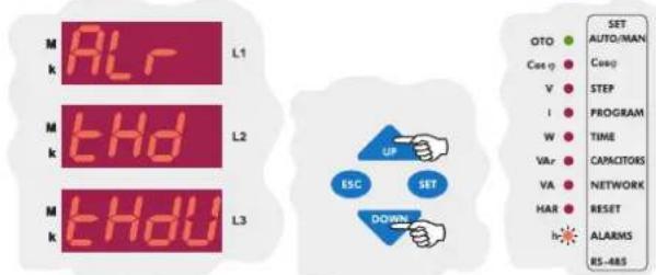
Using the "UP/DOWN" buttons, find the delay time(dELy) menu.
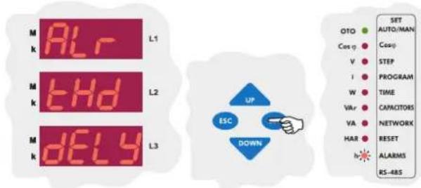
Press the "SET" button for delay time menu(dELy) which is the second setting in the harmonic menu.


Enter the delay time for overvoltage harmonic between 0-999,9 seconds and press "SET" button.


If you want to leave the setup menu without making any other changes, press the "ESC" button until "SAVE SET yES" shows on the screen. If you want to save the changes, press the "SET" button. If not, press the "ESC" button.
3.9.d.c Programming the Switching Off of the Capacitor Steps in Case of Harmonic Alarm
In order to protect the capacitors from overvoltage harmonic, they can be set to switch off in case of a harmonic alarm in this menu.
If "on" option is selected, when overvoltage harmonic error occurs, capacitor steps stay switched on.
If "of" option is selected, when overvoltage harmonic error occurs, capacitor steps switch off.


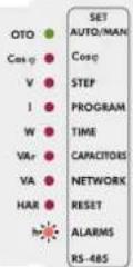
Using the "UP/DOWN" buttons, find capacitor step(StEP) menu.


Press the "SET" button for capacitor step menu which is the third setting in the harmonic menu.


Using the "UP/DOWN" buttons, select "on"(capacitors stay switched on) or "of"(capacitors switch off) option and press "SET" button. If you are going to change another setting, return to the menu by pressing the "SET" button. If you do not want to set another parameter, press the "ESC" button.

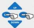
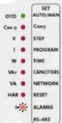
If you want to leave the setup menu without making any other changes, press the "ESC" button until "SAVE SET yES" shows on the screen. If you want to save the changes, press the "SET" button. If not, press the "ESC" button.
3.10 Fan Relay Settings
The values for switching on and switching off are entered in this menu. There are two submenus as "FAn on" and "FAn oFF" in this menu. Note: Temperature measurement feature for RG3-12C/CS is optional.
3.10.a Switch On Value for Fan Relay
Fan relay switching on temperature is programmed in this menu. Relay is switched on after 10 sec. when the measured temperature increase the set value and Fan led light will be on.
3 sec. Press the "SET" button for 3 sec. in order to enter to the menu.
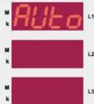


Using the "UP/DOWN" buttons, find fan relay settings(FAn) menu.


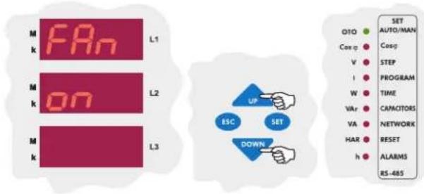
First setting of the fan relay menu is is the operating temperature of the fan. Press "SET" button to enter this menu.
Press the "SET" button to enter the fan switch on temperature value.
Using the "UP/DOWN" buttons, find "FAn off" menu which is the second setting in the fan relay menu.

Enter the temperature alarm between "00.0-99.8" °C and press the "SET" button. If you are going to change another setting, return to the menu by pressing the "SET" button. If you do not want to set another parameter, press the "ESC" button.
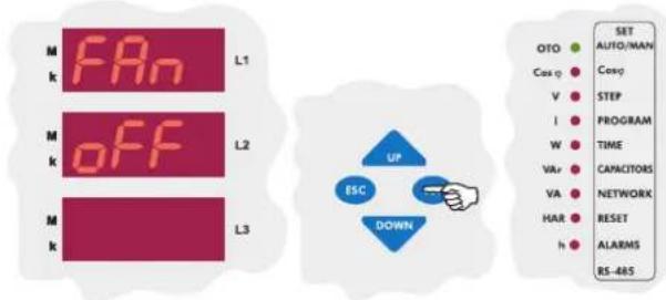
Press the "SET" button to program the switch off value for the fan relay.
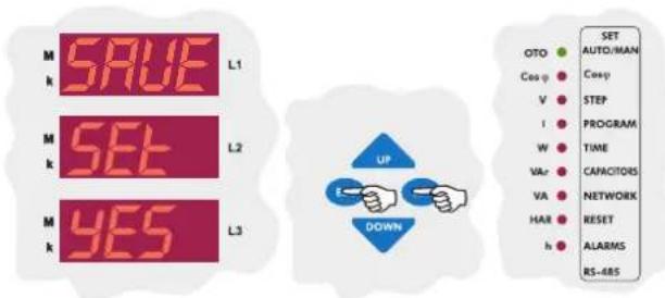
If you want to leave the setup menu without making any other changes, press the "ESC" button until "SAVE SET yES" shows on the screen. If you want to save the changes, press the "SET" button. If not, press the "ESC" button.
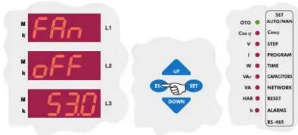
Press "SET" button to enter the temperature alarm between "00.0-99.8" °C(A higher value than "FAn on" value can not be programmed). If you are going to change another setting, return to the menu by pressing the "SET" button. If you do not want to set another parameter, press the "ESC" button.
3.10.b Switch Off Value for Fan Relay
Fan relay switching off temperature is programmed in this menu.
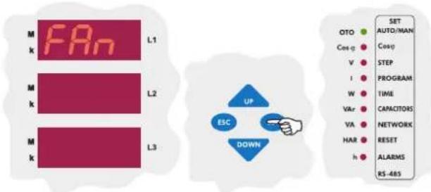
The first parameter in the Fan menu(FAn) is the operating temperature of the fan. Press "SET" button to enter the operating temperature settings.

If you want to leave the setup menu without making any other changes, press the "ESC" button until "SAVE SET yES" shows on the screen. If you want to save the changes, press the "SET" button. If not, press the "ESC" button.
3.11 Resetting the Energy Counters and Entering the Energy Values
RG3-12C/CS has 2 energy counters. "Energy Counter 1" is the energy counter which can be read from the measurement parameters. "Energy Counter 2" can only be read from the devices registers.
For "Energy Counter 1"; the energy value can be entered with "0,1 kWh/kVArh" precision for Active Import(A-I), Active Export(A-E), Reactive Inductive(r-L) and Reactive Capacitive(r-C) energy types. For "Energy Counter 2"; entering a value from the menu is not possible. If communication for the device exists, the energy values can be entered with "0,1 kWh/kVArh" precision for both counters. Resetting the energy counters can be done from this menu. Energy counters can also be conditioned to work with the generator input.
3.11.a Entering the Energy Values
Note: This process is done the same way for Active Import(A-I), Active Export(A-E), Reactive Inductive(r-L) and Reactive Capacitive(r-C) energy types.
3 sec. Press the "SET" button for 3 sec. in order to enter to the menu.

Using the "UP/DOWN" buttons, find the energy menu(EnErgy).
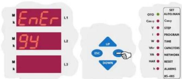
Press the "SET" to enter the energy menu. The first option in the energy menu is the Active Import Export(A-I) value.
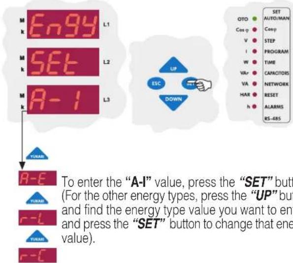

Active import energy value can be entered between "00000000.1 - 99999999.9". Enter the desired value and press the "SET" button.

If you want to leave the setup menu without making any other changes, press the "ESC" button until "SAVE SET YES" shows on the screen. If you want to save the changes, press the "SET" button. If not, press the "ESC" button.
3.11.b Resetting the Energy Values
RG3-12C/CS has 2 energy counters. These counters can be reset independently. Resetting is done the same way for both of the counters.

Press the "SET" to enter the energy menu. The first option in the energy menu is the Active Import Export(A-I) value.

Using the "UP/DOWN" buttons, find the energy reset menu (Engy CLr En-1 / Engy CLr En-2).

To reset the energy counter 1, press the "SET" button.
Using the "UP/DOWN" buttons, select "yES" to reset the energy counters or select "no" to cancel the resetting and press the "SET" button.
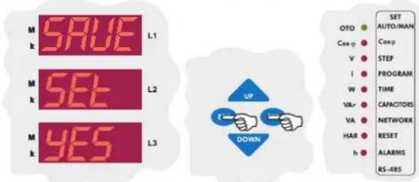
If you want to leave the setup menu without making any other changes, press the "ESC" button until "SAVE SET yES" shows on the screen. If you want to save the changes, press the "SET" button. If not, press the "ESC" button.
3.11.c Conditioning the Energy Counters to Work with the Generator Input
The conditioning of the energy counters is done in this menu. There are 2 parameters. If the "gEn ACt no" parameter is selected, Energy Counter 1 and Energy Counter 2 will count simultaneously. If the "gEn ACt yES" parameter is selected; when a signal on the generator input exists, Energy Counter 1 stops counting and Energy Counter 2 starts to count. When the signal disappears, Energy Counter 2 stops counting and Energy Counter 1 starts to count. This way, Energy Counter 2 can be set as a generator energy counter.

To enter to the Energy menu, press the "SET" button. The first option in the Energy menu is the Active Import Energy Value(A-I).
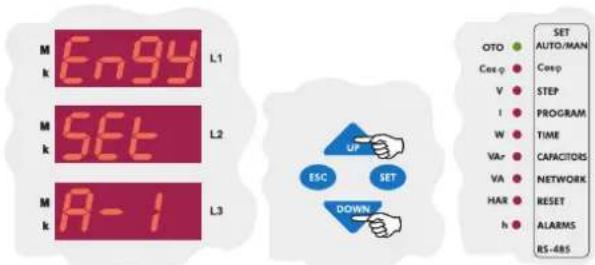
Using the "UP/DOWN" buttons, find the menu for conditioning the energy counters(Engy SET gEn).

Press the "SET" button to enter this menu. "gEn ACt no" will be displayed.
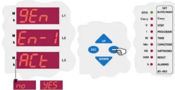
In order for the energy counter 1 to stop counting and energy counter to start counting when there is a signal on the generator input, select "yES" or in order for the energy counters to count simultaneously, select "no" using the "UP/DOWN" buttons and press the "SET" button.

If you want to leave the setup menu without making any other changes, press the "ESC" button until "SAVE SET yES" shows on the screen. If you want to save the changes, press the "SET" button. If not, press the "ESC" button.
3.11 Computer Communication Settings (RS-485) RG3-12C/CS has MODBUS-RTU communication protocol. All measured parameters can be saved into computer's memory via appropriate software. Additionally, all necessary configurations also can be set via software.
NOTE: Computer communication feature is only available for RG3-12CS model.
3.11.a Device Address Setting
By changing the device address setting, communication up to 247 devices can be achieved.
3 sec. Press the "SET" button for 3 sec. in order to enter to the menu.

Using the "UP/DOWN" buttons, find computer communication menu (RS-485).


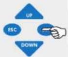

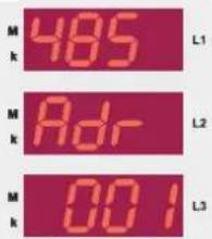
The first parameter in the computer communication menu(RS-485) is the address setting(Adr). Prass the "SET" button for address setting.
Press the "SET" button to enter the baud rate menu(bAUd).


Press the "SET" button to set the address value.
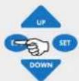

Using the "UP/DOWN" buttons, enter baud rate value (1.200 - 2.400 - 4.800 - 9.600 - 19.200 - 38.400) and press the "SET" button. If you are going to change another setting, return to the menu by pressing the "SET" button. If you do not want to set another parameter, press the "ESC" button.


Enter the communication address between 1-247 and press the "SET" button. If you are going to change another setting, return to the menu by pressing the "SET" button. If you do not want to set another parameter, press the "ESC" button.

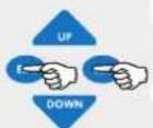

If you want to leave the setup menu without making any other changes, press the "ESC" button until "SAVE SET YES" shows on the screen. If you want to save the changes, press the "SET" button. If not, press the "ESC" button.
3.11.b Baud Rate Setting
In this menu, baud rate value can be set as 1.200 Kbps, 2.400 Kbps, 4.800 Kbps, 9.600 Kbps, 19.200 Kbps or 38.400 Kbps as defined in the communication software.


If you want to leave the setup menu without making any other changes, press the "ESC" button until "SAVE SET YES" shows on the screen. If you want to save the changes, press the "SET" button. If not, press the "ESC" button.
3.11.c Parity Setting
In this menu, Parity value can be set as "no", "odd" or "EVEn".

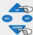

Using the "UP/DOWN" buttons, find the parity menu(PAr) menu which is the third parameter in the RS-485 menu.
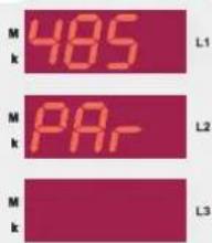


Using the "UP/DOWN" buttons, find baud rate menu(bAUd) which is the second parameter in the RS-485 menu.
Press the "SET" button to enter the parity menu(PAr).
Using the "UP/DOWN" buttons, select a parity option and press the "SET" button. If you are going to change another setting, return to the menu by pressing the "SET" button. If you do not want to set another parameter, press the "ESC" button.

If you want to leave the setup menu without making any other changes, press the "ESC" button until "SAVE SET yES" shows on the screen. If you want to save the changes, press the "SET" button. If not, press the "ESC" button.
3.12 Password Activation and Change Settings
User password can be changed and activated in this menu. When the password is activated, a pin code is always required before entering to the menu.
Thus, user password prevents any change to the settings of the device by unauthorized people. For this reason, a pin code with 4 digits must be set and then it must be activated.
Note: Factory default value for pin code is "1234" and it is not activated.
3.12.a Pin Activation
In this menu, user password is activated. When the password is activated, a pin code is always required before entering to the menu.
3 sec.
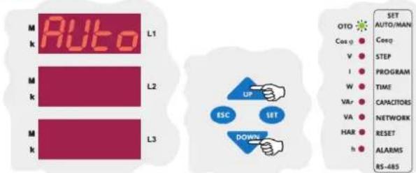
Using the "UP/DOWN" buttons, find "Pin" menu.

Press "SET" button to enter the password menu.
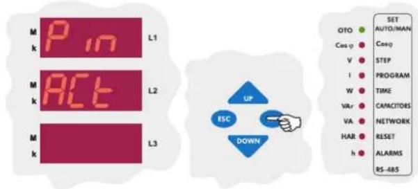
The first parameter in the password menu is the parameter activation menu(Pin ACt). According to this setting, password for the device menu can be set "inactive" or "active". Press the "SET" button to enter this menu.
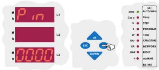
If you did not activate the password before, enter the pin code as "1234". If you changed the password before, enter that password. Press "SET" button to change the password activation setting.
Note: While entering the pin code, the blinking digit represents the digit which will be set. Press the "UP/DOWN" buttons to increase/decrease the value of the related digit. Press "SET" button to set the next digit or press "ESC" button to set previous digit.
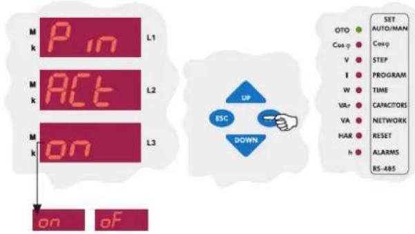
Using the "UP/DOWN" buttons, select the "Pin ACt" as "on" or "of" and then press the "SET" button. If you are going to change another setting, return to the menu by pressing the "SET" button. If you do not want to set another parameter, press the "ESC" button.

If you want to leave the setup menu without making any other changes, press the "ESC" button until "SAVE SET yES" shows on the screen. If you want to save the changes, press the "SET" button. If not, press the "ESC" button.
Note: If you do not save your changes, they will not be valid.
Note: After the settings in the menu are done, the changed settings are selected and the menu can be shown by pressing the "SET" button. If you want to leave the setup menu without making any other changes, press the "ESC" button until "SAVE SET yES" shows on the screen. If you press the "SET" button, the new settings will be saved and the device will start to operate with the new settings. If you press the "ESC" button, the changed settings will be discarded and the device will continue to operate with the old settings.
3.12.b Pin Change
In this menu, user password is changed. In order to change the password, old password and new password (x2 times) must be entered.
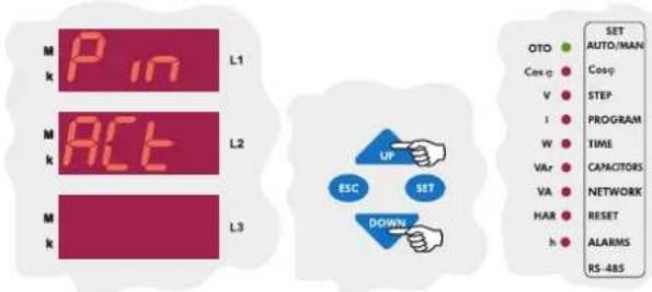
In "Pin ACt" menu, press the "DOWN" button to find "Pin CHg" menu.

Press the "SET" button to enter the password change menu(Pin CHg) which is the second menu under the password menu(Pin). Press the "SET" button to change the password.

In order to define a new password, the old password must be entered first. After entering the old password, press the "SET" button.

After entering new password, press the "SET" button.

Enter the new password again and press the "SET" button. If you are going to change another setting, return to the menu by pressing the "SET" button. If you do not want to set another parameter, press the "ESC" button.
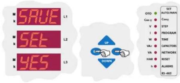
If you want to leave the setup menu without making any other changes, press the "ESC" button until "SAVE SET YES" shows on the screen. If you want to save the changes, press the "SET" button. If not, press the "ESC" button.
In the "Instantaneous Values" menu, below network parameters can be observed by using the "UP", "DOWN" and "SET" buttons.
| Voltage _k | - | Currents | - | Cosφ | - | ΣCosφ | - | Active (W) | - | Reactive (VAr) |
| Apparent (VA) | - | ΣPowers | - | Energies | - | THD%V | - | THD%I | - | Temperature |
By pressing the "ESC" button repeatedly in any menu, "Instantaneous Values" menu can be displayed.
This is the main menu of RG3-12C/CS. If you wait without pressing the buttons in any menu, "Instantaneous Values" menu is displayed automatically.
When RG3-12C/CS is energised for the first time, "Instantaneous Values" menu is displayed.
Cosφ
When the device is energised, Cosφ values of the 3-phases are displayed. A negative (-) sign indicates that the phase is capacitive and a positive (+) sign indicates that the phase is inductive. As you can see in the example below; Cosφ value of the first phase is capacitive, Cosφ value of the second and third phases are inductive.
While observing cosφ values, if "SET" button is pressed (HAR LED lights), harmonic values can be observed up to 19th (odd-numbered) harmonics.

flowchart
graph TD
    A["SET"] --> B["SET"]
    B --> C["SET"]
    C --> D["SET"]
    D --> E["SET"]
    E --> F["SET"]
    F --> G["SET"]
    G --> H["SET"]
    H --> I["SET"]
    I --> J["SET"]
    J --> K["SET"]
    K --> L["SET"]
    L --> M["SET"]
    M --> N["SET"]
    N --> O["SET"]
    O --> P["SET"]
    P --> Q["SET"]
    Q --> R["SET"]
    R --> S["SET"]
    S --> T["SET"]
    T --> U["SET"]
    U --> V["SET"]
    V --> W["SET"]
    W --> X["SET"]
    X --> Y["SET"]
    Y --> Z["SET"]
Cosφ and HAR LEDs on the display indicate that the displayed values are harmonic values of the related cosφ. By pressing the "SET" button repeatedly, odd-numbered harmonic values up to 19th harmonic can be observed.
Total Cosφ
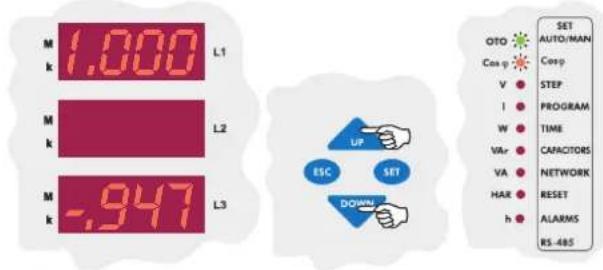
When Cosφ values are displayed, if "DOWN" button is pressed, Total Inductive Cosφ and Total Capacitive Cosφ values are observed. As you can see in the example below, total inductive Cosφ value is displayed on the first display and total capacitive cosφ value is displayed on the third display.
Voltages
In the measurement mode, phase-neutral voltages can be displayed by using "UP/DOWN" buttons when V LED lights. When phase voltages are displayed, if "SET" button is pressed (HAR LED lights), harmonic values up to 19th harmonic(odd-numbered) can be observed.
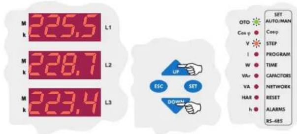

flowchart
graph TD
    A["SET"] --> B["L1"]
    B --> C["L2"]
    C --> D["L3"]
    D --> E["ETd"]
    E --> F["L1"]
    F --> G["L2"]
    G --> H["L3"]
    H --> I["0074 L1"]
    I --> J["L1"]
    J --> K["0062 L2"]
    K --> L["L2"]
    L --> M["0048 L3"]
    M --> N["0052 L1"]
    N --> O["L1"]
    O --> P["0041 L2"]
    P --> Q["L2"]
    Q --> R["0036 L3"]
    R --> S["0020 L1"]
    S --> T["L1"]
    T --> U["H-05"]
    U --> V["L2"]
    V --> W["L3"]
    W --> X["0037 L2"]
    X --> Y["L3"]
    Y --> Z["0045 L3"]
V and HAR LEDs on the display indicate that displayed values are voltage harmonic values. By pressing the "SET" button repeatedly, THD and odd-numbered harmonic values up to 19th harmonic can be observed as %.
In the measurement mode, phase-phase current values can be displayed by using "UP/DOWN" buttons when I LED lights.
When phase current values are displayed, if "SET" button is pressed (HAR LED lights), odd-numbered harmonic values up to 19th harmonic can be observed.

flowchart
graph TD
    A["SET"] --> B["SET"]
    B --> C["SET"]
    C --> D["SET"]
    D --> E["SET"]
    E --> F["SET"]
    F --> G["SET"]
    G --> H["SET"]
    H --> I["SET"]
    I --> J["SET"]
    J --> K["SET"]
    K --> L["SET"]
    L --> M["SET"]
    M --> N["SET"]
    N --> O["SET"]
    O --> P["SET"]
    P --> Q["SET"]
    Q --> R["SET"]
    R --> S["SET"]
    S --> T["SET"]
    T --> U["SET"]
    U --> V["SET"]
    V --> W["SET"]
    W --> X["SET"]
    X --> Y["SET"]
I and HAR LEDs on the display indicate that displayed values indicate current harmonic values. By pressing the "SET" button repeatedly, THD and odd-numbered harmonic values up to 19th harmonic can be observed as %.
Active Powers
In the measurement mode, active power values can be displayed by using "UP/DOWN" buttons when W LED lights. When active power values are displayed, if "SET" button is pressed (HAR LED lights), odd-numbered harmonic values up to 19th harmonic can be observed.
Active power values of the phases are displayed on the display. If the dot at the most right of the value blinks, the active power on this phase is export active power.

flowchart
graph TD
    A["SET"] --> B["SET"]
    B --> C["SET"]
    C --> D["SET"]
    D --> E["SET"]
    E --> F["SET"]
    F --> G["SET"]
    G --> H["SET"]
    H --> I["SET"]
    I --> J["SET"]
    J --> K["SET"]
    K --> L["SET"]
    L --> M["SET"]
    M --> N["SET"]
    N --> O["SET"]
    O --> P["SET"]
    P --> Q["SET"]
    Q --> R["SET"]
    R --> S["SET"]
    S --> T["SET"]
    T --> U["SET"]
    U --> V["SET"]
    V --> W["SET"]
    W --> X["SET"]
    X --> Y["SET"]
    Y --> Z["SET"]
W and HAR LEDs on the display indicate that displayed values are active power harmonic values. By pressing the "SET" button repeatedly, odd-numbered harmonic values up to 19th harmonic can be observed.
Total Active Powers
When active power values are displayed, if the "DOWN" button is pressed, import active and export active power values are displayed. As seen in the example below, total active import power value is displayed on the first display and total active export value is displayed on the third display.
Note: The dot at the most right digit of the third display indicates that the displayed value is export value.

In the measurement mode, reactive power values are displayed by using "UP/DOWN" buttons when VAr LED lights. When reactive power values are displayed, if "SET" button is pressed (HAR LED lights), odd-numbered harmonic values up to 19th harmonic can be observed.
Apparent Powers
In the measurement mode, apparent power values are displayed by using the "UP/DOWN" buttons when VA LED lights. When apparent power values are displayed, if the "SET" button is pressed (HAR led lights), odd-numbered harmonic values up to 19th harmonic can be observed.

flowchart
graph TD
    A["SET"] --> B["SET"]
    B --> C["SET"]
    C --> D["SET"]
    D --> E["SET"]
    E --> F["SET"]
    F --> G["SET"]
    G --> H["SET"]
    H --> I["SET"]
    I --> J["SET"]
    J --> K["SET"]
    K --> L["SET"]
    L --> M["SET"]
    M --> N["SET"]
    N --> O["SET"]
    O --> P["SET"]
    P --> Q["SET"]
    Q --> R["SET"]
    R --> S["SET"]
    S --> T["SET"]
    T --> U["SET"]
    U --> V["SET"]
    V --> W["SET"]
    W --> X["SET"]
    X --> Y["SET"]
    Y --> Z["SET"]
VAr and HAR LEDs on the display represent that displayed values indicate harmonic values of the reactive powers. By pressing the "SET" button repeatedly, odd-numbered harmonic values up to 19th harmonic can be observed.
Total Reactive Powers
When active power values are displayed, if the "DOWN" button is pressed, inductive reactive and capacitive reactive power values are observed. As seen in the example below, total reactive inductive power value is displayed on the first display and total reactive capacitive power value is displayed on the third display.
Note : The dot at the most right digit of the third display indicates that the displayed value is capacitive reactive power.


flowchart
graph TD
    A["SET"] --> B["SET"]
    B --> C["SET"]
    C --> D["SET"]
    D --> E["SET"]
    E --> F["SET"]
    style A fill:#f9f,stroke:#333
    style B fill:#ccf,stroke:#333
    style C fill:#cfc,stroke:#333
    style D fill:#fcc,stroke:#333
    style E fill:#cff,stroke:#333
    style F fill:#ffc,stroke:#333
VA and HAR LEDs on the display indicate that displayed values are harmonic values of the apparent powers. By pressing "SET" button repeatedly, odd-numbered harmonic values up to 19th harmonic can be observed.
Total Apparent Powers
When apparent power values are displayed, if the "DOWN" button is pressed, total apparent power is displayed on the second display.
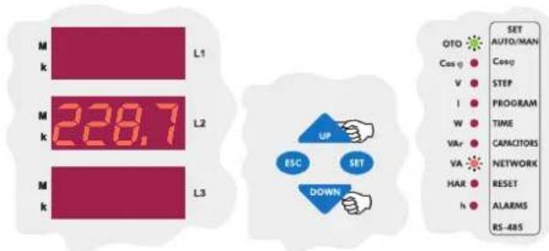
Active Import Energy
In the measurement mode, active import and active export energy values can be observed by using "UP/DOWN" buttons, when W and h LEDs light.
In the example below, “I” indicates that the displayed parameter is import energy and the remaining numbers show the energy value(such as 203385706,8 kWh).

Active Export Energy
While active import energy is displayed, if the "DOWN" button is pressed, active export energy is displayed.
In the example below, “E” indicates that the displayed parameter is export energy and the remaining numbers show the energy value(such as 45168,3 kWh).

Note : When you reset the energies using the energy counter reset menu, active and reactive energy values are both reset (Refer to Page 14 - Reactive / Active ratio reset settings).
Inductive Reactive Energy
In the measurement mode, inductive reactive and ca pacitive reactive energy values can be observed by using the "UP/DOWN" buttons when VAr and h LEDs light.
In the example below, “1” indicates that the displayed parameter is import energy(inductive) and the remaining numbers show the energy value (such as 7649,3 kVarh).


On the first display, the measured Inductive/Active ratio is displayed and on the third display, the entered Inductive/Active ratio is displayed. (Refer to page 18 - Inductive ratio setting)
Capacitive Reactive Energy
In the example below, “E” indicates that the displayed parameter is export(capacitive) energy and the remaining numbers show the energy value(such as 4035386,2 kVArh).


On the first display, the measured Capacitive/Active ratio is displayed and on the third display, the entered Capacitive/Active ratio is displayed.
(Refer to page 17 - Inductive ratio setting)
Note: When you reset the reactive/active ratio, the value in the first display will be reset and updated continuously.
(Refer to page 14 - Reactive/Active ratio setting)
Temperature
The temperature value which is measured via externally connected thermocouple is displayed on the display.
Below; the display indicates that measured temperature is 45^ C.
Note: This feature is optional.

Error Codes

If any failure occurs for any reason, related Alarm LED is turned on. If the related error code needs to be displayed by the user, the "UP/DOWN" buttons are pressed until "Error-xx" is displayed on the displays. This option is not displayed if there is no error. All the error codes are displayed respectively by pressing the "SET" button(such as Error-05, 07, 12).
Note : The descriptions of the error codes are given in the alarm codes table(Refer to Page 31 - Alarm Codes).
| ALARM CODES | |||
| NO | DESCRIPTION REASON | LED | |
| 00 | Angle degree between phase voltages doesn't equal to 120° | Neutral and Voltage terminal connections are incorrect. | |
| 01 | Reverse phase sequence | Voltage terminal connections are in counter-clockwise direction | |
| 02 | One or more phase voltages don't exist | Voltage terminal connections are wrong | |
| 03 | Phase 1 Current | Current transformer connections for phase 1 are wrong or first capacitor step is defected | |
| 04 | Phase 2 Current | Current transformer connections for phase 2 are wrong or first capacitor step is defected | |
| 05 | Phase 3 Current | Current transformer connections for phase 3 are wrong or first capacitor step is defected | |
| 06 | THD for voltage exceeds the preset value | Excessive harmonic exists in the system | |
| 07 | Voltage value of any phase exceeds the preset value | Voltage value of the system is increased | |
| 08 | Reactive capacitive ratio exceeds the preset value | % | Compensation Error |
| 09 | Reactive inductive ratio exceeds the preset value | % | Compensation Error |
| 10 | Temperature of the capacitors exceeds the preset value | Overheating | |
| 11 | Automatic connection could not be found | Defected capacitor step or variable loads | |
| 12 | Over compensation | Target Cos is capacitive even if all capacitor steps are switched off | |
| 13 | Insufficient compensation | Capacitor powers are not sufficient for target Cos | |
| 14 | RST step sequence is incorrect | 3-phase capacitor powers were not selected properly | |
| 15 | Capacitor power for phase 1 is not suitable | Capacitor step powers for phase 1 were not selected properly | |
| 16 | Capacitor power for phase 2 is not suitable | Capacitor step powers for phase 2 were not selected properly | |
| 17 | Capacitor power for phase 3 is not suitable | Capacitor step powers for phase 3 were not selected properly | |
| 18 | Capacitor step 1 is defected | In the capacitor step measurement, 3-phase capacitor step is unbalanced or the fuse of any phases is blown | |
| 19 | Capacitor step 2 is defected | In the capacitor step measurement, 3-phase capacitor step is unbalanced or the fuse of any phases is blown | |
| 20 | Capacitor step 3 is defected | In the capacitor step measurement, 3-phase capacitor step is unbalanced or the fuse of any phases is blown | |
| 21 | Capacitor step 4 is defected | In the capacitor step measurement, 3-phase capacitor step is unbalanced or the fuse of any phases is blown | |
| 22 | Capacitor step 5 is defected | In the capacitor step measurement, 3-phase capacitor step is unbalanced or the fuse of any phases is blown | |
| 23 | Capacitor step 6 is defected | In the capacitor step measurement, 3-phase capacitor step is unbalanced or the fuse of any phases is blown | |
| 24 | Capacitor step 7 is defected | In the capacitor step measurement, 3-phase capacitor step is unbalanced or the fuse of any phases is blown | |
| 25 | Capacitor step 8 is defected | In the capacitor step measurement, 3-phase capacitor step is unbalanced or the fuse of any phases is blown | |
| 26 | Capacitor step 9 is defected | In the capacitor step measurement, 3-phase capacitor step is unbalanced or the fuse of any phases is blown | |
| 27 | Capacitor step 10 is defected | In the capacitor step measurement, 3-phase capacitor step is unbalanced or the fuse of any phases is blown | |
| 28 | Capacitor step 11 is defected | In the capacitor step measurement, 3-phase capacitor step is unbalanced or the fuse of any phases is blown | |
| 29 | Capacitor step 12 is defected | In the capacitor step measurement, 3-phase capacitor step is unbalanced or the fuse of any phases is blown | |
| 30 | Capacitor step 13 is defected | In the capacitor step measurement, 3-phase capacitor step is unbalanced or the fuse of any phases is blown | |
| 31 | Capacitor step 14 is defected | In the capacitor step measurement, 3-phase capacitor step is unbalanced or the fuse of any phases is blown | |
*Optional
In the first column, total reactive power values of 3-phase capacitors and in second & third columns, reactive power values of the capacitors in single phase system are shown.
| Operating Voltage (Un) | : Please look at the rear label of the device. |
| Operating Voltage Range ΔU | :(0.9-1.1) x Un |
| Operating Current Range ΔI | : 50 mA-5.5 A |
| Frequency | : 50 Hz / 60 Hz |
| Measurement Class | : 1% ±1 digit (V, I, Cosφ),2% ±1 digit (W, VAr, VA, Wh) (100mA-5.5A) |
| Power Consumption | :<2 VA (Current)3 VA - 10 VA (Voltage) |
| Output Contact | : 5 A, 250 V AC, 1250 VA |
| Generator Input | : 110 V AC ~ 250 V AC |
| No-Volt Feature | : In case of a power failure (for phase 1)longer than 20 msec. , all capacitor steps are disconnected automatically |
| Setting Range | |
| Cosφ Setting | :-0,800 ... 0,800 |
| Cosφ2 Setting | :-0,800 ... 0,800 |
| CT Ratio | : 1 - 2000 |
| VT Ratio | : 1 - 2000 |
| Switching on&off and Discharge | |
| Time Setting for Capacitor Steps | : Switching on & off and discharge times can be set between 1 - 1800 sec. |
| Step Number | : 12 |
| Over Voltage Setting | : Selectable |
| Ambient Temperature Range | :-5°C ... 55°C |
| Measurement Temp. Range* | : 00.0 °C ... 100 °C |
| Display | : Red LED Display with 4 digits |
| Equipment Protection Class | : Double Insulation (☐) |
| Wires Crossection (for terminals) | : 2.5 mm2 |
| Box Protection Class | : IP 00 (Terminal)IP 40 (Front panel) |
| Installation | : Flush mounting with rear terminals |
| Dimension | : Type PR16 |
| Panel Cut-out | : 139 x 139 mm |
| Weight | : 0.85 kg. |
| RS-485 Communication ** | |
| Address | : 1 - 247 |
| Baud Rate | : 1.200 Kbps, 2.400 Kbps, 4.800 Kbps,9.600 Kbps, 19.20 Kbps, 38.40 Kbps |
| Parity | :no, odd, even |
| Factory Set Values | |
| Automatic Connection Correction | : On |
| Target Cosφ | : 1,000 (inductive) |
| Target Cosφ2 | : 0.900 (inductive) |
| Program | : PS10 |
| t-on (switch-on delay) | : 10 sec. |
| t-off (switch-off delay) | : 10 sec. |
| Discharge time | : 14 sec. |
| Overvoltage | : 260.0 V AC |
| Delay | : 3.0 sec. |
| Step protection | : Off |
| Over Harmonic | : 7.0% |
| Delay | : 1.0 sec. |
| Step protection | : Off |
| Inductive Ratio Range | : 25 |
| Capacitive Ratio Range | : 15 |
| Temperature Protection * | |
| Alarm Value | : 55 °C |
| Step Protection | : Off |
| Lower Alarm | : 53 °C |
| Fan Setting * | |
| Operation Temperature | : 45 °C |
| Lower Temp. Value | : 40 °C |
| CT Ratio | : 1 |
| VT Ratio | : 1 |
| RS-485 Communication | |
| Address | : 1 |
| Baud Rate | : 9.600 Kbps |
| Parity | :no |
* Optional
** Only available for RG3-12CS
↓ START
RG3-12C/CS MENU MAP
INSTANT VALUES
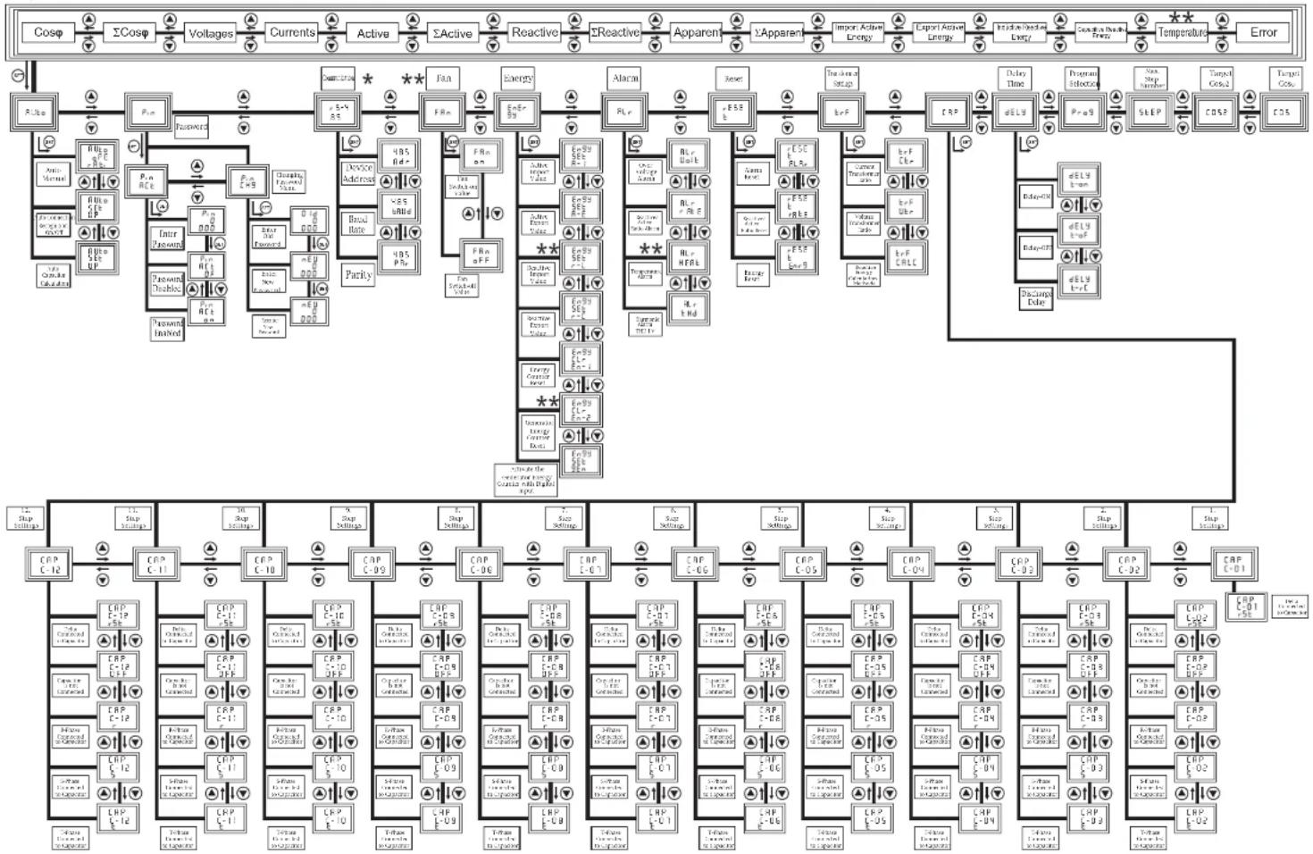
flowchart
graph TD
    A["Cosφ"] --> B["ΣCosφ"]
    B --> C["Voltages"]
    C --> D["Currents"]
    D --> E["Active"]
    E --> F["ΣActive"]
    F --> G["Reactive"]
    G --> H["ΣReactive"]
    H --> I["Apparent"]
    I --> J["ΣApparent"]
    J --> K["Import Active Energy"]
    K --> L["Export Active Energy"]
    L --> M["Inj蘇/Outkai Lowg"]
    M --> N["Consum & Drain Tempens"]
    N --> O["Temperature"]
    O --> P["Error"]

    subgraph Power Supply
        Q["R_Uso"] --> R["P_in"]
        R --> S["Reservoir"]
        S --> T["Device Address"]
        T --> U["Parity"]
        U --> V["Fan"]
        V --> W["Energy"]
        W --> X["Alarm"]
        X --> Y["Reset"]
        Y --> Z["Standard Setup"]
        Z --> AA["TRP"]
        AA --> AB["Delay Time"]
        AB --> AC["Program Selective"]
        AC --> AD["Step"]
        AD --> AE["COS"]
        AE --> AF["COS"]

    subgraph Control Components
        AG["Anti-Moment"] --> AH["P_in R_E"]
        AH --> AI["Enter Password"]
        AI --> AJ["Device Doublets"]
        AJ --> AK["Device Doublets"]
        AK --> AL["Device Doublets"]
        AL --> AM["Device Doublets"]
        AM --> AN["Device Doublets"]
        AN --> AO["Device Doublets"]
        AO --> AP["Device Doublets"]
        AP --> AQ["Device Doublets"]
        AQ --> AR["Device Doublets"]
        AR --> AS["Device Doublets"]
        AS --> AT["Device Doublets"]
        AT --> AU["Device Doublets"]
        AU --> AV["Device Doublets"]
        AV --> AW["Device Doublets"]
        AW --> AX["Device Doublets"]
        AX --> AY["Device Doublets"]
        AY --> AZ["Device Doublets"]
        AZ --> BA["Device Doublets"]
        BA --> BB["Device Doublets"]
        BB --> BC["Device Doublets"]
        BC --> BD["Device Doublets"]
        BD --> BE["Device Doublets"]
        BE --> BF["Device Doublets"]
        BF --> BG["Device Doublets"]
        BG --> BH["Device Doublets"]
        BH --> BI["Device Doublets"]
        BI --> BJ["Device Doublets"]
        BJ --> BK["Device Doublets"]
        BK --> BL["Device Doublets"]
        BL --> BM["Device Doublets"]
        BM --> BN["Device Doublets"]
        BN --> BO["Device Doublets"]
        BO --> BP["Device Doublets"]
        BP --> BQ["Device Doublets"]
        BQ --> BR["Device Doublets"]
        BR --> BS["Device Doublets"]
        BS --> BT["Device Doublets"]
        BT --> BU["Device Doublets"]
        BU --> BV["Device Doublets"]
        BV --> BW["Device Doublets"]
        BW --> BX["Device Doublets"]
        BX --> BY["Device Doublets"]
        BY --> BZ["Device Doublets"]
        BZ --> CA["Device Doublets"]
        CA --> CB["Device Doublets"]
        CB --> CC["Device Doublets"]
        CC --> CD["Device Doublets"]
        CD --> CE["Device Doublets"]
        CE --> CF["Device Doublets"]
        CF --> CG["Device Doublets"]
        CG --> CH["Device Doublets"]
        CH --> CI["Device Doublets"]
        CI --> CJ["Device Doublets"]
        CJ --> CK["Device Doublets"]
        CK --> CL["Device Doublets"]
        CL --> CM["Device Doublets"]
        CM --> CN["Device Doublets"]
        CN --> CO["Device Doublets"]
        CO --> CP["Device Doublets"]
        CP --> CQ["Device Doublets"]
        CQ --> CR["Device Doublets"]
        CR --> CS["Device Doublets"]
        CS --> CT["Device Doublets"]
        CT --> CU["Device Doublets"]
        CU --> CV["Device Doublets"]
        CV --> CW["Device Doublets"]
        CW --> CX["Device Doublets"]
        CX --> CY["Device Doublets"]
        CY --> CZ["Device Doublets"]
    end

    subgraph Control Signals
        DA["CPP_C-12"] --> DB["CPP_C-11"] --> DC["CPP_C-10"] --> DD["CPP_C-09"] --> DP["CPP_C-08"] --> DC["CPP_C-07"] --> DV["CPP_C-06"] --> DW["CPP_C-05"] --> DX["CPP_C-04"] --> DP["CPP_C-03"] --> DP["CPP_C-02"] --> DP["CPP_C-01"] --> DP["CPP_C-00"] --> DP["CPP_C-01"] & DP["CPP_C-00"] & DP["CPP_C-01"] & DP["CPP_C-00"] & DP["CPP_C-01"] & DP["CPP_C-00"] & DP["CPP_C-01"] & DP["CPP_C-00"] & DP["CPP_C-01"] & DP["CPP_C-00"] & DP["CPP_C-01"] & DP["CPP_C-00"] & DP["CPP_C-01"] & DN_CPP_C-01 & DN_CPP_C-00 & DN_CPP_C-01 & DN_CPP_C-00 & DN_CPP_C-01 & DN_CPP_C-00 & DN_CPP_C-01 & DN_CPP_C-00 & DN_CPP_C-01 & DN_CPP_C-00 & DN_CPP_C-01 & DN_CPP_C-00 & DN_CPP_C-01 & DN_CPP_C-00 & DN_CFP_C-01 & DN_CFP_C-00 & DN_CFP_C-01 & DN_CFP_C-00 & DN_CFP_C-01 & DN_CFP_C-00 & DN_CFP_C-01 & DN_CFP_C-00 & DN_CFP_C-01 & DN_CFP_C-00 & DN_CFP_C-01 & DN_CFP_C-00 & DN_CFP_C-01 & DN_CFP_C-01 & DN_CFP_C-00 & DN_CFP_C-01 & DN_CFP_C-00 & DN_CFP_C-01 & DN_CFP_C-01 & DN_CFP_C-00 & DN_CFP_C-01 & DN_CFP_C-01 & DN_CFP_C-01 & DN_CFP_C-01 & DN_CFP_C-01 & DN_CFP_C-01 & DN_CFP_C-01 & DN_CFP_C-01 & DN_CFP_C-01 & DN_CFP_C-01 & DN_CFP_C-01 & DN_CFP_C-01 & DN_CFP_C-01 & DN_CF_P - DN_F - DN_F - DN_F - DN_F - DN_F - DN_F - DN_F - DN_F - DN_F - DN_F - DN_F - DN_F - DN_F - DN_F - DN_F - DN_F - DN_F - DN_F - DN_F - DN_F - DN_F - DN_F - DN_F - DN_F - DN_F - DN_F - DN_F - DN_F - DN_F - DN_F - DN_F - DN_F - DN_F - DN_F = PN_P - PN_P
    end
* Available for RG3-12CS.
** Not available for models without temperature module
A4917/Rev.1
- Precautions for Safe Use and Installation....1
- Important Note for System Connection ....1
- INTRODUCTION 2
- INSTALLATION OF RG3-12C/CS 5
- SETTINGS 5
- DISPLAYING OF INSTANTANEOUS VALUES ......28
- APPENDIX 32
- Precautions for Safe Use and Installation
- Important Note for System Connection.
- Generator Input Connection
- Monitoring the measured temperature
- Measured Parameters :
- Front Panel
- 1.2.a Button Functions
- Rear Panel
- Warnings :
- Commissioning of RG3-12C/CS
- Capacitor Sequence Setting
- SETTINGS
- Manual Operation Mode, Automatic Capacitor Recognition Mode and Automatic Connection Control Mode
- 3.1.a Manuel Operation Mode Setting
- 3.1.c Automatic Connection Recognition Mode Setting
- Target Cosφ and Target Cosφ2 Value Setting
- 3.2.a Inductive / Capacitive Cosφ and Cosφ2 Setting
- Region
- Last Capacitor Step Number Setting
- Selection of Proper Switching Sequence
- Switching On&Off and Discharge Time Settings
- 3.5.a Switch-On Delay Time Setting
- 3.5.b Switch-Off Delay Time Setting
- Power Value and Connection Type Settings for Capacitors
- 3.6.a First Capacitor Step Setting
- 3.6.b Second Capacitor Step Setting
- CAP C-03
- CAP C-04
- CAP C-05
- CAP C-06
- CAP C-07
- CAP C-08
- CAP C-09
- CAP C-10
- CAP C-11
- CAP C-12
- Current and Voltage Transformer Ratio Settings
- 3.7.a Current Transformer Ratio Setting
- sec.
- 3.7.c Reactive Energy Calculation Method Setting
- 3.8.a Alarm Reset Setting
- 3.8.b Reactive/Active Ratio Reset Setting
- 3.9.a Overvoltage Alarm Setting
- 3.9.a.a Overvoltage Setting
- 3.9.a.b Overvoltage Delay Time Setting
- 3.9.a.c Switch On or Switch Off Setting of Capacitor Steps for Overvoltage Alarm Setting
- 3.9.b Reactive / Active Ratio Setting
- 3.9.b.a Capacitive Ratio Setting
- 3.9.b.b Inductive Ratio Setting
- 3.9.c Temperature Alarm Settings
- 3.9.c.b Programming the Lower Limit of Temperature Alarm
- 3.9.c.c Programming the Switching Off of the Capacitor Steps in Case of Overheating
- 3.9.d.a Overvoltage Harmonic Setting
- 3.9.d.b Harmonic Alarm Delay Time Setting
- 3.9.d.c Programming the Switching Off of the Capacitor Steps in Case of Harmonic Alarm
- Fan Relay Settings
- 3.10.a Switch On Value for Fan Relay
- 3.10.b Switch Off Value for Fan Relay
- Resetting the Energy Counters and Entering the Energy Values
- 3.11.a Entering the Energy Values
- 3.11.b Resetting the Energy Values
- 3.11.c Conditioning the Energy Counters to Work with the Generator Input
- 3.11.a Device Address Setting
- 3.11.b Baud Rate Setting
- 3.11.c Parity Setting
- Password Activation and Change Settings
- 3.12.a Pin Activation
- 3.12.b Pin Change
- Cosφ
- Total Cosφ
- Voltages
- Active Powers
- Total Active Powers
- Apparent Powers
- Total Reactive Powers
- Total Apparent Powers
- Active Import Energy
- Active Export Energy
- Inductive Reactive Energy
- Capacitive Reactive Energy
- Temperature
- Error Codes
- ↓ START
- RG3-12C/CS MENU MAP
- INSTANT VALUES
Brand : ENTES
Model : RG3-15CLS
Category : Electric regulator