
Statement E2 - Speaker Martin Logan - Free user manual and instructions
Find the device manual for free Statement E2 Martin Logan in PDF.


| Product Type | Floorstanding Hybrid Electrostatic Loudspeaker |
| Model | Statement E2 |
| Brand | Martin Logan |
| Driver Configuration | Electrostatic panel (curved) + dual 12-inch powered woofers |
| Frequency Response | 25 Hz – 22 kHz ± 3 dB |
| Impedance | 4 ohms nominal, 2 ohms minimum |
| Sensitivity | 88 dB / 2.83 V / 1 meter |
| Power Handling | 100 – 400 watts RMS |
| Recommended Amplifier Power | 100 – 500 watts per channel |
| Dimensions (H × W × D) | 72 in × 19 in × 27 in (183 cm × 48 cm × 69 cm) |
| Weight | 150 lbs (68 kg) per speaker |
| Enclosure Type | Hybrid: open-baffle electrostatic panel + sealed woofer cabinet |
| Finish Options | Black, White, Cherry, Walnut (with fabric grille) |
| Input Terminals | Bi-wire capable (gold-plated 5-way binding posts) |
| Power Supply | AC 100–240 V, 50/60 Hz (for electrostatic panel bias supply) |
| Power Consumption (idle) | 15 W (standby), 0.5 W (eco mode) |
| Included Accessories | Power cord, jumpers for bi-wire, cleaning cloth, spider spikes |
| Warranty | 5 years limited (speaker drivers and electrostatic panel) |
| Cleaning | Use microfiber cloth; avoid liquids on electrostatic panel; vacuum dust from woofers |
| Safety | Do not expose to moisture; ensure stable placement; disconnect power during cleaning |
| Spare Parts / Repairability | Contact authorized service centers for replacement electrostatic panels and woofers |
Frequently Asked Questions - Statement E2 Martin Logan
User questions about Statement E2 Martin Logan
0 question about this device. Answer the ones you know or ask your own.
Ask a new question about this device
Download the instructions for your Speaker in PDF format for free! Find your manual Statement E2 - Martin Logan and take your electronic device back in hand. On this page are published all the documents necessary for the use of your device. Statement E2 by Martin Logan.
USER MANUAL Statement E2 Martin Logan
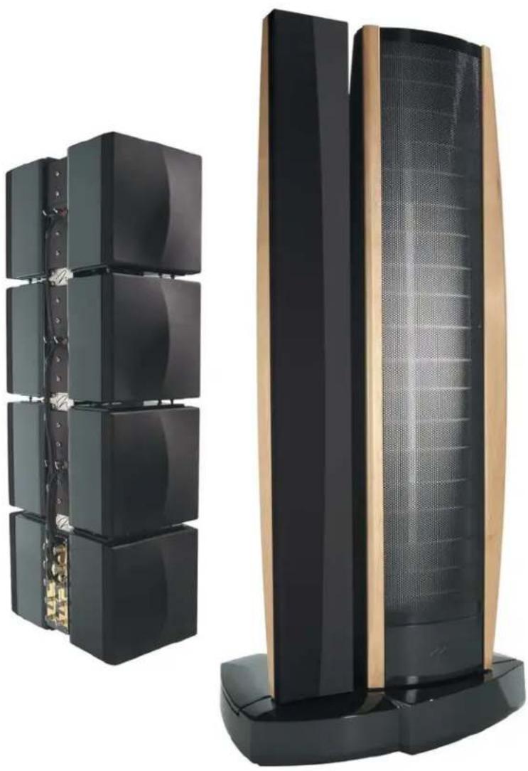
STATEMENT™ E2 setup manual
natural_image
Two black and gold electronic speakers with grid-like structures, one upright and one tilted (no visible text or symbols)CONTENTS
Contents 2
Before You Begin ....3
Master Packing List
Required Tools
Unpacking the Statement e2
Speaker Placement ....4
Initial Speaker Placement
The Wall Behind the Listener
The Wall Behind the Speakers
The Side Walls
Assembly 5
Subwoofer Tower Assembly
Transition/ESL Tower Assembly .....10
Connections—Exos Crossover Inputs .....21
Connections—Exos Crossover Outputs .....22
Subwoofer Outputs
Full Range Outputs
Connections—ESL/Transition Towers .....23
Bi-Wire Connection
Horizontal Passive Bi-Amplification
Vertical Passive Bi-Amplification .....24
Connections—Subwoofer Towers .....25
8-Ohm Connection
2-Ohm Connection
4-Ohm Bi-Amp Connection
Passive Hi-Pass Settings .....26
The High-Pass Settings
AC Power Connection .....28
Making It Work Together .....29
Making It Work Together (Part 1)
Subwoofer Level Knob
Setting the Dip Switches
Making It Work Together (Part 2)....30
Speaker Placement (Fine Tuning) .....31
Hard Sound
Tweaking the Room
Master Packing List Required Tools
Before you being setting up the Statement e2, please make sure that all 15 crates/boxes are present and accounted for. The list below gives a detailed description of what can be found in each numbered crate/box.
# Contents
Sub (Left)
1 Master Sub, Left
2 Middle Sub, Left
3 Middle Sub, Left
4 Top Sub, Left
Sub (Right)
5 Master Sub, Right
6 Middle Sub, Right
7 Middle Sub, Right
8 Top Sub, Right
ESL/Transition Towers
9 Trim & Sub Harness x 2
10 ESL Towers x 2
11 Transition Towers x 2
12 Instruction Box (Hardware, tools, etc.)
Base (Left)
13 Base Assembly, Left
Base (Right)
14 Bass Assembly, Right
EXOS
15 EXOS Electronic Crossover
Provided (in crate 12):
—9/16"Socket
—7/32" Hex head
—Ratcheting screwdriver
—Grill cloth tool
You will need to provide:
—#2 Phillips head screwdriver
—Small standard screwdriver
—Level
—Cordless drill with a #2 phillips head bit
Not required, but useful:
— ^1/4 "Drive ratchet with extension
— ^1/4 "Open end wrench
—Cotton gloves
Unpacking the Statement E2

WARNING! Unpacking the Statement Evolution 2 electrostatic speaker system requires a minimum of two people. Do not attempt any part of the unpacking process with one person.
1 Using a power drill and a #2 Phillips head drill bit, remove the screws from the tops of all crates. Remove the top of each crate and set it aside, preferably in another room.
2 Unpack the contents of the 4 left sub crates near the front left corner of the room. Remove the crates from the room.
3 Unpack the contents of the 4 right sub crates near the front right corner of the room. Remove the crates from the room.
4 Unpack the contents of the 4 ESL/Transition tower crates in an out of the way spot in the room. Remove the crates from the room.
5 Unpack the contents of the left base crate near the left side of the room approximately 7 feet from the front wall. Remove the crates from the room.
6 Unpack the contents of the right base crate near the right side of the room approximately 7 feet from the front wall. Remove the crates from the room.
Initial Speaker Placement The Wall Behind the Listener
For optimal performance of the Statement e2 system we recommend that the ESL/Transition towers be placed approximately five to seven feet from the front wall (the wall in front of the listening position) and at least two feet from the side walls. The subwoofer towers should be placed diagonally (or against a wall) in the front corners of the room with at least one foot of clearance between the woofers and the walls. The listening position should be farther than the distance between the speakers themselves. What you are trying to attain is the impression of good center imaging and stage width (see figure 1).
There is no exact distance between speakers and listener, but there is a relationship. In long rooms, naturally, that relationship changes. The distance between the speakers will be far less than the distance from you to the speaker system. However, in a wide room, you will still find that if the distance from the listener to the speakers becomes smaller than the distance between the speakers themselves, the image will no longer focus in the center.

Figure 1. Initial Speaker Placement.
4 Speaker Placement
Near-field reflections can occur from your back wall, the wall behind the listening position. If your listening position is close to the back wall, these reflections can cause problems and confuse the quality of imaging. Actually it is better for the wall behind you to be soft rather than bright. If you have a hard back wall and your listening position is close to it, experiment with devices that will soften and absorb information (i.e., wall hangings and possibly even sound absorbing panels).
The Wall Behind the Speakers
The front surface, the wall behind your speakers, should not be extremely hard or soft. For instance, a pane of glass will cause reflections, brightness and confused imaging. Curtains, drapery and objects such as bookshelves can be placed along the wall to soften a hard surface. A standard sheet rock or textured wall is generally an adequate surface if the rest of the room is not too bright and hard. Sometimes walls can be too soft. If the entire front wall consists of only heavy drapery, your system can sound too soft or dull. You may hear dull, muted music with little ambience. Harder room surfaces will actually help in this case.
The front surface should, optimally, be one long wall without any doors or openings. If you have openings, the reflection and bass characteristics from one channel to the other can be different.
The Side Walls
The same requirements exist for side walls. Additionally, a good rule of thumb is to have the side walls as far away from the speaker sides as possible, minimizing near-field side wall reflections. Sometimes, if the system is bright or the imaging is not to your liking, and the side walls are very near, try putting curtains or softening material directly to the edge of each speaker. An ideal side wall, however, is no side wall at all.
Subwoofer Tower Assembly

WARNING! Assembling the Statement e2 requires two people, except for step 12 of the subwoofer tower assembly, which requires three people. Do not attempt any part of the assembly process with one person.
1 Place the primary subwoofer module in position on the floor, (the primary module has 10 binding posts). Corner placement is recommended—it is important to place the sub towers as close to final position as possible, as the final assembled tower weighs approximately 500 lb. However, for assembly you must leave enough space to have access to all sides of the sub tower. Place a level in position as shown to level the module left to right. Adjust the glider pads on the bottom of the cabinet to achieve level.
2 Position the level as shown to level the primary module front to back, adjusting the glider pads on the bottom of the cabinet to achieve level.
3 Pick up a secondary module with an assembler on each end and place carefully onto the primary module by lining up the cone feet on the secondary with the indentations at each corner of the primary module. Use your index finger as shown to feel when the cone feet are in position.

natural_image
Exterior view of a modern office building (no signage)Figure 2

natural_image
Close-up of a yellow and gold mechanical device mounted on black blocks, with no visible text or symbols.Figure 3

natural_image
Person assembling a black electronic device with buttons and connectors (no visible text or symbols)Figure 4
natural_image
Close-up of a person using a wooden ruler to handle a black mechanical component, with an inset close-up showing a bracket (no visible text or symbols)Figure 5

natural_image
Black electronic device with attached wooden beam and metallic components, placed indoors near a cylindrical wall (no visible text or symbols)Figure 6

natural_image
Close-up of hands installing a red wavy line on a black electronic panel, with a close-up of the same hand holding a blue plastic plate (no text or symbols visible)Figure 7
6 Assembly
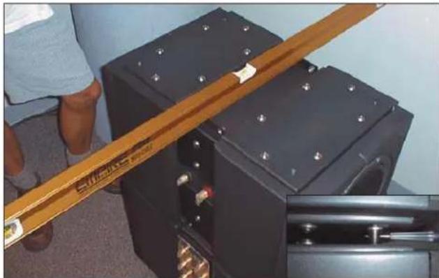
4 After the second module is in position atop the primary module, place a level on it as shown. Level the module front to back by inserting a small allen wrench (or other suitable instrument) through the hole in the cones on the base of the module (detail), and rotating the cone up or down to achieve level.
5 Level the module left to right with the level in position as shown. Adjust the cone feet for height.
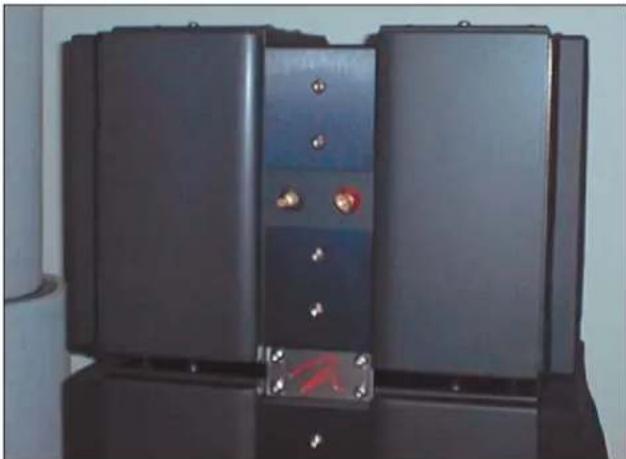
6 Once the secondary module is level, install the stainless steel Martin-Logan logo plates. You have a choice of using either a blue or red backing behind the logo—the vinyl insert is two-sided. Peel the protective plastic from the insert and position the insert between the logo plate and line up with the mounting holes on the top and bottom of the sub modules as shown. Insert the 3/8"-16 x 1" button head cap screws—do not tighten until all 4 screws are started, and then tighten in a cross-pattern so that all screws tighten down together. Use a 7/32" allen wrench.
7 Stack the next secondary module atop the second utilizing the same assembly procedure used in step 3.
8 Align the cones to the indentations on the cabinet below, and level the module front-to-back and left-to-right, following the same procedure used in steps 4 and 5.
9 Repeat the procedure in step 6.

natural_image
Two men adjusting a black electronic device with buttons, standing indoors (no visible text or symbols)Figure 8

natural_image
Person adjusting a black electronic device with metal contacts (no visible text or symbols)Figure 9

natural_image
Stacked black audio equipment units with speaker heads, alongside a close-up of hands adjusting a red wire on a device (no visible text or symbols)Figure 10
natural_image
Black electronic device with two buttons and a red mark on the side panel (no visible text or symbols)Figure 11
10 Place the fourth and final module in position (repeating steps 3 thru 6). The top module is distinguished from the other modules by the lack of mounting holes on the top bracket (as shown).
natural_image
Close-up of two black electronic components with circular cutouts, one being held by a hand (no visible text or symbols)Figure 12
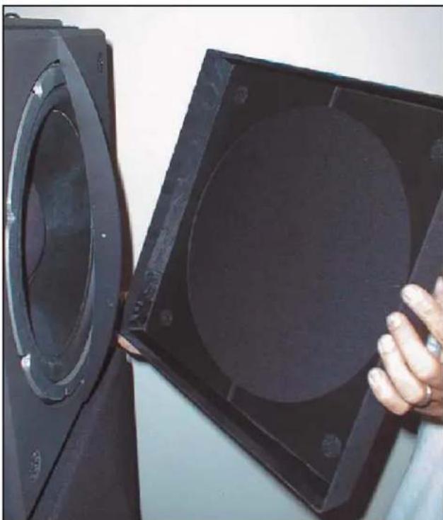
11 Align the slots on the top and bottom of the grill cloth frames with the curved extrusion on the module. Place firmly into position so that the velcro fasteners are securely meshed.
12 Install woofer wiring harness as shown. You can move the tower to the preferred listening position by shifting the unit from side to side and "walking" it.

natural_image
Stacked black electronic device with connected cables and connectors, placed on a white wall (no visible text or symbols)Figure 13
13 When you are confident the sub tower is correctly positioned, mark the floor with masking tape at each corner. Install the spikes by using a safe dolly to tip the sub tower back, remove the glides, and then screw the spikes into place. Make sure you thread the large black rubber washer onto the spike post before installing in the tower. Place the tower in a vertical position, and level front to back by tilting the tower back (at least 3 people are required) and adjusting the spikes.
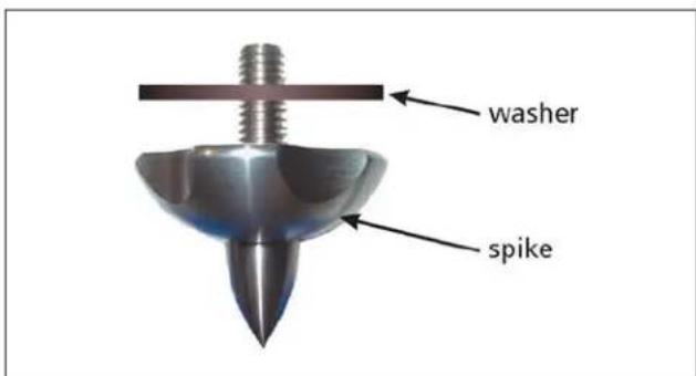
Figure 14
Transition/Electrostatic Tower Assembly
Note: The following instructions describe the assembly of the right channel high-and mid-frequency tower. Duplicate all assembly instructions for the left tower assembly.

natural_image
Close-up of a speaker tower with two speakers and red cables attached, mounted on a wooden panel (no visible text or symbols)Figure 15

natural_image
Close-up of hands adjusting a mechanical component with a tool (no visible text or symbols)Figure 16

natural_image
Person adjusting a door panel with a tool, no visible text or symbolsFigure 17
10 Assembly
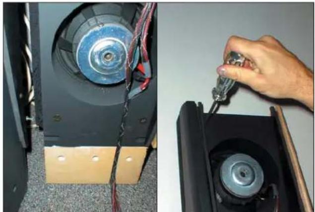
1 Attach the outside (semi-circle shaped) trim rail to the transition tower by aligning the five pins on the trim rail with the 5 cam holes in the tower.
2 Use a phillips head screwdriver to rotate the cams a little over 180° counter clockwise once the pin is properly aligned in the cam. The arrow on the cam must be in the position shown to accept the pin.

natural_image
Close-up of a metallic screw head and a metallic pin with 'wing' label (no other text or symbols)3 Make sure the trim rail is flush with the tower edge.
4 Install the inside wing (wedge shaped with pins on the side) trim rail by aligning the 5 pins with the corresponding cams as in the previous assembly, only this time the cams turn clockwise to lock in the trim wing.
natural_image
Two-panel image showing a speaker with exposed circuit board and wiring, and a hand holding a tool near a speaker's head (no visible text or symbols)Figure 18
5 Finished transition tower assembly.

natural_image
Two black speaker-mounted panels with circular buttons, displayed indoors against a plain wall (no text or symbols visible)Figure 19

natural_image
Two-panel photo showing a man adjusting a black device with a child inside, both in a room with equipment (no visible text or symbols)Figure 20

natural_image
Close-up of hands performing maintenance on a red coil device with wires and components (no visible text or symbols)Figure 21
natural_image
Person operating a red and black electronic device with visible wiring and components (no text or symbols)Figure 22
12 Assembly
6 Pick up the transition tower assembly and insert it as shown into the base so the three holes in the mounting bracket line up with the holes in the tower.
7 Push the tower towards the center for proper alignment.
8 Once the holes are properly aligned, insert the 3 ^1/2 " x ^9/16 " hex head lag screws through a steel washer and into the tower. Finger tighten—do not tighten all the way.
9 Use a level to bring the tower 90 degrees vertical left to right.
10 When the tower is perfectly plumb, go ahead and tighten the bolts securely.
11 Use your level to plumb the tower front to back.

natural_image
Man in white robe adjusting a gold-colored vertical panel in a room with stacked black equipment (no visible text or symbols)Figure 23

natural_image
Close-up of hands installing or repairing a car interior panel with red tools (no visible text or symbols)Figure 24
natural_image
Man in white robe adjusting a door panel indoors, no visible text or symbolsFigure 25

natural_image
Close-up of electrical components including a black cylindrical device, red copper coils, and a coiled wire (no visible text or symbols)Figure 26
12 Tighten tower wing bolt.

natural_image
Close-up of a hand using a tool to switch a red coil in a mechanical device (no visible text or symbols)Figure 27
13 Tighten base bolts.
natural_image
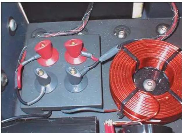
Close-up of an electrical control panel with red and black components, coiled red coils, and wiring (no visible text or symbols)Figure 28
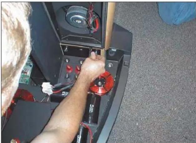
14 Connect the tower as shown (red to red, black to black).
14 Assembly
15 Install the ESL wing trim (wedge shaped with pins on the narrow end) by aligning the 5 pins with the corresponding cams. The cams turn clockwise to lock the trim with in place.
16 Insert the electrostatic panel as shown.
17 Line up holes and insert the 2 ^1/4 " x ^9/16 " button head cap screws (black) through a steel washer and into the tower. Finger tighten.

natural_image
Close-up of two black electronic devices with a metallic clip and a circular button, no visible text or symbols.Figure 29

natural_image
Technician working on electronic equipment with tools and wiring (no visible text or symbols)Figure 30

natural_image
Close-up of hands installing or adjusting a circuit board with visible wiring and components (no text or symbols)Figure 31
natural_image
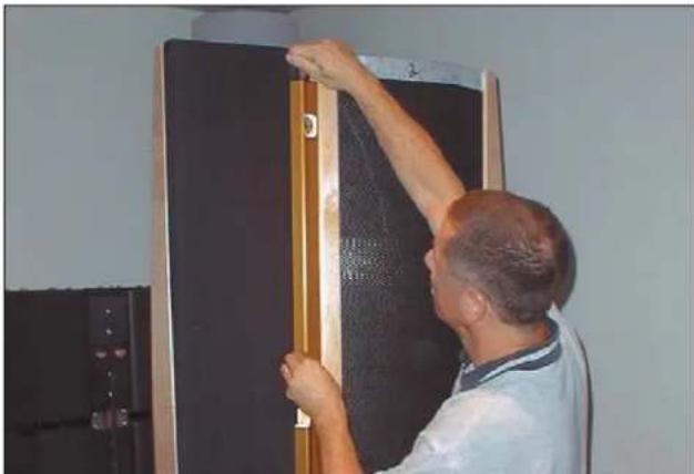
Man installing or adjusting a black door panel with a wooden handle (no visible text or symbols)Figure 32

natural_image
Close-up of hands adjusting a wooden plank with a ruler, showing measurement details (no text or symbols visible)Figure 33

natural_image
Close-up of hands working on an electronic circuit board with wires and components (no visible text or symbols)Figure 34
16 Assembly
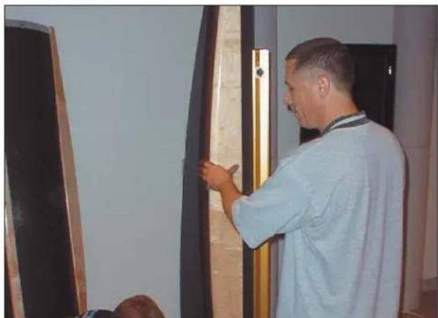
18 Use a level to plumb the electrostatic panel left-to-right.
19 Measure the space between towers (top and bottom). The space should measure exactly 2 inches.
20 Tighten frame bolts as shown.
21 Use a level to plumb the electrostatic panel front-to-back.
22 Tighten wing bolts.
23 Tighten base bolts.

natural_image
Man adjusting a door panel in a room, no visible text or symbolsFigure 35

natural_image
Close-up of hands using a multimeter to adjust or install electronic components on a circuit board (no visible text or symbols)Figure 36

natural_image
Close-up of a hand using a power tool to inspect or adjust electronic components on a circuit board (no visible text or symbols)Figure 37

natural_image
Close-up of hands assembling a white plastic component on a black base (no visible text or symbols)Figure 38

natural_image
Close-up of hands using a screwdriver to adjust components on a circuit board (no visible text or symbols)Figure 39

natural_image
Close-up of electronic circuit components including red and blue wires, connectors, and a green PCB (no visible text or symbols)Figure 40
18 Assembly
24 Connect light bar
25 Connect electrostatic panel wires to the color-coded screw-terminal connector.
26 ESL panel properly connected.
27 Find the loops at the top of the transition tower grill sock.
28 Hook the loops as indicated at the top of the tower.
29 Hook the loops on the bottom of the sock on the bottom of the tower as indicated.

natural_image
Close-up of hands holding a dark fabric, possibly a garment or cloth, with no visible text or symbols.Figure 41

natural_image
Close-up of hands adjusting a dark panel with a white object on the left (no visible text or symbols)Figure 42
natural_image
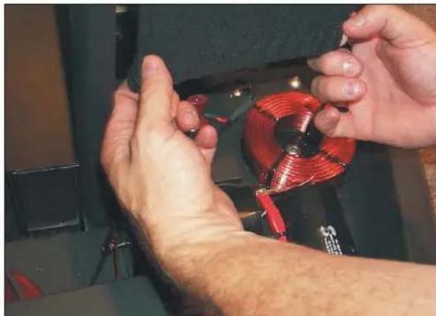
Close-up of hands performing a mechanical repair or tooling task with a red coil and black components (no visible text or symbols)Figure 43

natural_image
Close-up of a hand using a blue tool to clean or inspect a mechanical component with red coil and black mounting bracket (no visible text or symbols)Figure 44

natural_image
Person assembling a black electronic device with a microphone, no visible text or symbolsFigure 45
30 Push the grill sock into the slot provided to stretch the cloth taut, from top to bottom.
31 Place the top of the base into position.
Note: You may want to wait before installing the top of the base as settings inside the base may need changing.
CONNECTIONS—EXOS CROSSOVER INPUTS
Connect the outputs of the Preamplifier/Processor to the inputs of the EXOS using either balanced or single ended connections. There are right channel, left channel and optional 0.1 effects channel inputs.

WARNING! Use either all balanced or all single ended connections for signal inputs. Do not use both.

Figure 46. EXOS signal inputs. Balanced connection shown.
Connect the EXOS subwoofer outputs to the amplifier(s) for the woofer towers using either balanced or single ended connections. Both the balanced and single ended outputs are always on—you can use either option to connect the woofer tower amplifier(s) regardless of which you used for signal input.
Note: Use either all balanced or all single ended connections for subwoofer outputs. Do not use both.
Full Range OutputsSubwoofer Outputs
Connect the full range outputs of the EXOS to the amplifier(s) for the ESL/Transition tower using the same type of connection used for the signal inputs.
Note: The full range outputs should use the same connectors as the signal inputs. They are directly connected together.

Figure 47. EXOS outputs. Balanced connections shown.
22 Connections—Exos Crossover Outputs
Bi-Wire Connection
This method of connection uses individual runs of speaker wire from your amplifier. This doubles the signal carrying conductors from the amplifier to the speaker, thus direct-coupling each portion of the crossover to the amplifier.
Connect one set of wires to the upper set of binding posts which connect to the ESL panel of the Statement e2. Then connect a second set of wires to the lower binding posts which connect to the transitions tower. Next, connect both sets of wires to the appropriate terminals on your amplifier. Please take care to connect both (+) wires to the (+) amplifier terminals and both (-) wires to the (-) amplifier terminals. This is known as a parallel connection (See Figure 48).
Horizontal Passive Bi-Amplification
Horizontal bi-amping allows you to use two different types, models or brands of amplifiers (i.e. tubes on top, transistor on the bottom). However, we recommend that you use two identical amplifiers (i.e. same brand and model). If you must use two different amplifiers, it is essential that they have the same gain or that one of the two have adjustable gain so that you can match their gain characteristics. If the amplifiers of choice do not have the same gain characteristics, then a sonic imbalance will occur.
With horizontal bi-amping, one amplifier drives the high pass (ESL) section while the second amplifier drives the low pass (WOOFER) section. Connect the low frequency amplifier to the lower set of binding posts of both speakers. Connect the high frequency amplifier to the upper set of binding posts (see figure 49).

flowchart
graph TD
    A["ESL Tower (High Frequency)"] -->|+| B["Transition Tower (Low Frequency)"]
    C["ESL Tower (High Frequency)"] -->|-| D["Transition Tower (Low Frequency)"]
    E["EMIANCE INPUT"] -->|+| B
    F["EMIANCE OUTPUT"] -->|-| D
    G["AMPLIFIER"] -->|-| B
    style A fill:#f9f,stroke:#333
    style C fill:#f9f,stroke:#333
    style E fill:#f9f,stroke:#333
    style F fill:#f9f,stroke:#333
    style G fill:#f9f,stroke:#333
    style B fill:#ccf,stroke:#333
    style D fill:#ccf,stroke:#333
    style D fill:#ccf,stroke:#333
    style B fill:#cff,stroke:#333
    style D fill:#cff,stroke:#333
Figure 48. Bi-wire connection. One Channel shown.

flowchart
graph TD
    A["Transition Tower (Low Frequency)"] --> B["High Amplifier"]
    C["Transition Tower (Low Frequency)"] --> D["High Amplifier"]
    E["ESL Tower (High Frequency)"] --> F["ESL INPUT"]
    G["ESL Tower (High Frequency)"] --> H["ESL INPUT"]
    I["ESL Tower (High Frequency)"] --> J["ESL INPUT"]
    K["ESL Tower (High Frequency)"] --> L["ESL INPUT"]
    M["ESL Tower (High Frequency)"] --> N["ESL INPUT"]
    O["ESL Tower (High Frequency)"] --> P["ESL INPUT"]
    Q["ESL Tower (High Frequency)"] --> R["ESL INPUT"]
    S["ESL Tower (High Frequency)"] --> T["ESL INPUT"]
    U["ESL Tower (High Frequency)"] --> V["ESL INPUT"]
    W["ESL Tower (High Frequency)"] --> X["ESL INPUT"]
    Y["ESL Tower (High Frequency)"] --> Z["ESL INPUT"]
Figure 49. Horizontal passive bi-amplification. One Channel shown.
Vertical Passive Bi-Amplification
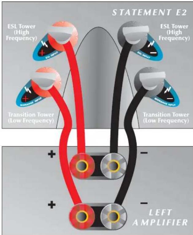
The very nature of vertical bi-amping dictates that both amplifiers be identical. With vertical bi-amping, each of the stereo amplifiers is dedicated to one speaker. For instance, the left channel of each amplifier drives the low pass (Transition) section while the right channel drives the high pass (ESL) section. Starting with one speaker, connect the right channel to the lower binding posts and the left channel to the upper binding posts. Repeat the same procedure for the other speaker. Connect the left preamplifier outputs to both inputs of the left channel amplifier and the right preamplifier outputs to both inputs of the right channel speaker (See Figure 50).
flowchart
graph TD
    A["Transition Tower (Low Frequency)"] --> B["ESL Tower (High Frequency)"]
    A --> C["ESL Tower (High Frequency)"]
    A --> D["ESL INPUT"]
    A --> E["Transition Tower (Low Frequency)"]
    F["Left Amplifier"] --> G["ESL Tower (High Frequency)"]
    F --> H["ESL INPUT"]
    F --> I["Transition Tower (Low Frequency)"]
    style A fill:#f9f,stroke:#333
    style F fill:#ccf,stroke:#333
    style B fill:#ff9,stroke:#333
    style C fill:#ff9,stroke:#333
    style D fill:#ff9,stroke:#333
    style E fill:#ff9,stroke:#333
    style G fill:#ff9,stroke:#333
    style H fill:#ff9,stroke:#333
Figure 50. Vertical passive bi-amplification. One Channel shown.
24 Connections—ESL/Transition Towers
8-Ohm Connection 4-Ohm/Bi-Amp Connection
This connection method is safe for all amplifiers (see figure 51).
Use this connection method if you wish to use two amplifiers to drive the subwoofer towers (see figure 53).
2-Ohm Connection
This connection is the loudest, but draws the most power from the amplifier (see figure 52). If using this connection method, make sure your amp can handle 2-Ohms.

Figure 51. 8-Ohm configuration. One channel shown.

Figure 52. 2-Ohm configuration. One channel shown.

Figure 53. 4-Ohm/bi-amp configuration. One channel shown.
The passive high-pass settings can be adjusted by changing the red and black jumpers found in the high-pass section of the ESL/Transition tower passive crossover.

WARNING! Before changing the passive-high pass options be sure to turn the amps off and unplug the Statement e2 ESL/Transition tower.
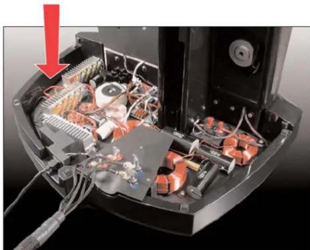
The design of these jumpers accommodates different listening distances to the speaker (distance between listener and speaker). The unit is shipped in 15ft mode. If the user is only 10-feet away the jumpers need to be changed.
The jumpers are located near the side of the crossover located in the ESL/Transition tower bases (see figure 54).
There are red and black jumpers that are either connected or not connected through the screw terminal block (see figure 56 & 57).

WARNING! Never connect the red wires to the black. wires.
natural_image
Interior view of an electronic device showing exposed circuitry and wiring, with a red arrow pointing to a component (no text or symbols visible)Figure 54. The location of the passive high-pass jumpers
The High-Pass Settings
The 4 options are (from least output to most output):
10-Foot Mode (figure 58)
—Red not connected and black connected. —0dB
All-Closed Mode (figure 59)
—Red connected and black connected —200Hz–300Hz +1dB
All-Open Mode (figure 60)
— Red not connected and black not connected —3dB peak at 300Hz
15-Foot Mode (default—(figure 61)
—Red connected and black not connected —200Hz–300Hz +1dB —3dB peak at 300Hz
Figure 55 demonstrates how these different settings effect the frequency response.
Note:
— The ten-foot mode has been set to 0db. — The all-closed setting raises the output from 200Hz to 700Hz by 1db — The all-open setting adds a peak of 3db around 300Hz — The 15-foot mode adds both of the above changes

line
| MODE | FREQUENCY (Hz) | SNOWING (Hz) | |------|----------------|--------------| | DIFF | 51.6 | 0.0x | | DIFF | 21.9 | 0.0x |Figure 55. The effects of the four jumper setting on frequency response relative to 10-foot mode.
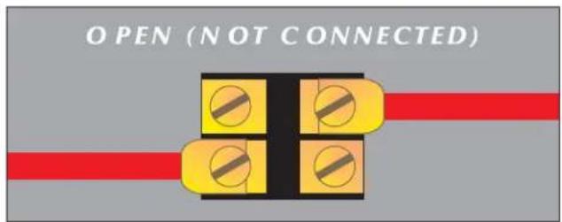
Figure 56. Open (not connected) jumpers.
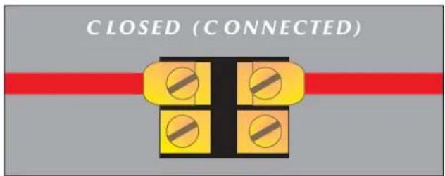
Figure 57. Closed (connected) jumpers.

Figure 58. Jumper settings for 10-foot mode.

Figure 59. Jumper settings for all-closed mode.

Figure 60. Jumper settings for all-open mode.

Figure 61. Jumper settings for 15-foot mode.
Because your MartinLogan Statement e2 ESL/Transition towers use an internal power supply to energize their electrostatic cells with high-voltage DC, they must be connected to an AC power source. The EXOS crossover must also be connected to an AC power source. For this reason the proper IEC standard power cords are provided. These cords should be firmly inserted into the AC power receptacles on the rear connection panel of the speakers and the EXOS, then to any convenient AC wall outlet. The ESL/Transition towers integrate a signal sensing power supply which will switch off after a few minutes of no music signal, and requires less than two seconds to recharge the panels when a music signal is present.

WARNING! Turn all amplifiers off when plugging in or unplugging the EXOS.
Your Statement e2 speakers and EXOS crossover are wired for the power service supplied in the country of original consumer sale. The AC power rating applicable to a particular unit is specified both on the packing carton and on the serial number plate attached to the speaker.
If you remove your Statement e2 speakers and EXOS crossover from the country of original sale, be certain that AC power supplied in any subsequent location is suitable before connecting and operating the speakers. Substantially impaired performance or severe damage may occur to a speaker if operation is attempted from an incorrect AC power source.

WARNING! The power cord should not be installed, removed, or left detached from the speaker while the other end is connected to an AC power source.
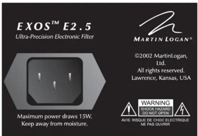
Figure 62. EXOS E2.5 IEC power cord AC receptacle.

Figure 63. Statement E2 IEC power cord AC receptacle.
Making It Work Together (Part 1) Setting the Dip Switches
Now that you know all the connection options and how to set them, it's time to make the speakers work in their target environment. For this part, it is recommended that an audio analyzer be used (RTA or a computer based instrument).
Start with default settings. Look at the 200Hz to 500Hz area of the ESL-transition tower alone. If there is too much energy in this area, try changing the jumpers in the passive high-pass accordingly (see page 26).
Note how low the transition tower is playing. The transition tower is somewhat dependent on back wall reflections for its low frequency extension. If it is set right it should respond well down to 60HZ.
If it does not play to 60Hz, the speaker is either to close or to far from the back wall. If the speaker is over 7 feet from the wall, try moving it back. If it is under 5 feet, try moving it out. Side wall distance can effect this as well. Some experimentation may be in order.
Subwoofer Level Knob
Setting the level too high will cause the bass to seem bloated and is the single most common cause of bad sounding subwoofers. A rule of thumb is that the subwoofer should not draw attention to itself, but should simply make the systems low end seem more extended and accurate.

Figure 64. The Exos E2.5 subwoofer level knob.
This should only be done by a qualified technician.
Note: Sonic measuring equipment is highly recommended for this part of the setup.
There are three controls that can be set by the dip switches located inside the EXOS (see figure 65):
— 25Hz Level (-8,-4,0,+4,+8)dB
— 50Hz Level (-8,-4,0,+4,+8)dB
— Phase Adjustment ( 0^ , 90^ , 180^ , 270^ )
How to adjust the dip switches:
1 Turn off all amplifiers connected to the EXOS.
2 Unplug the unit.
3 Remove the lid.
4 If more output is desired at 25Hz flip the +4dB or the +8dB dip switches to on. If less bass is desired at 25Hz flip the -4dB or the -8dB dip switches to on.
Left

25Hz
Right

25Hz

50Hz

50Hz
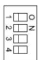
Phase
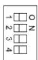
Phase
Figure 65. The exos six dip switch clusters. All set in their default position.
You will need to set the dip switches for both right and left channel. Note: Only one dip switch per dip switch cluster should be on at a time.
5 If available, use test equipment to optimize the subwoofer response.
6 The 50Hz control works the same as the 25Hz control.
7 The phase settings allow the phase of the woofer section to be modified in the crossover area. This allows for a phase match between the ESL/transition-tower and the subwoofer. The phase dip switch should be set to 270^ to start. We have found this setting to work well in most situations. To adjust the phase see figure four.
8 Replace the lid.
9 Plug the unit in.
10 Turn the amplifier on.
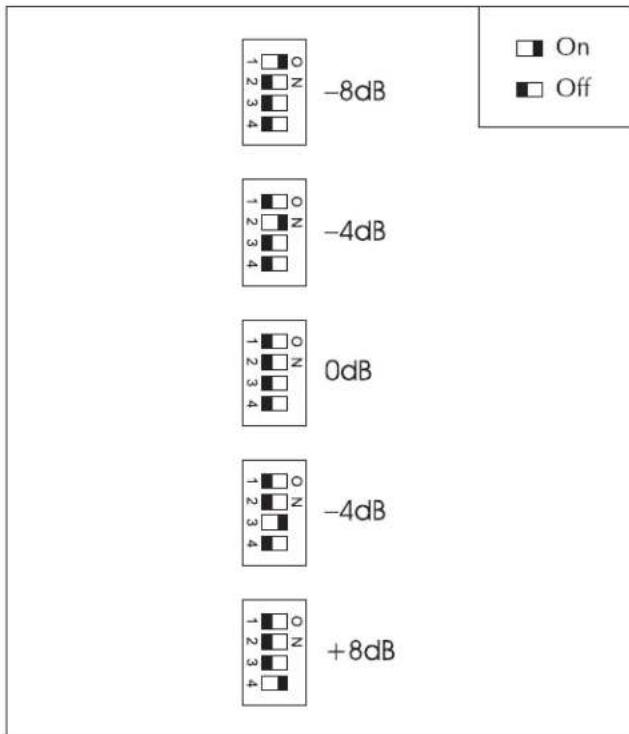
Figure 66. The five setting options for the 251 Hz and 501 Hz dip switches
Making It All Work Together (Part 2)
Note: This unit will generate electrical transients on its outputs when the power is turned off or on. This can cause loud noises if the amplifiers are turned on.
Turn on both the woofer and ESL/transition-tower. Try turning the woofer level up and down on the EXOS. This will allow you to see how the crossover is meeting. If you turn the woofer up and a suck-out appears at the crossover frequency the phase switch on the EXOS needs to be adjusted.
Adjusting the phase switch is best accomplished by trying different settings with the amplitude of the woofer output matching that of the ESL. Find the setting that creates the biggest suck-out at the crossover point. Now flip the switches to 180° from that position. Almost always the 270° default position is the best.
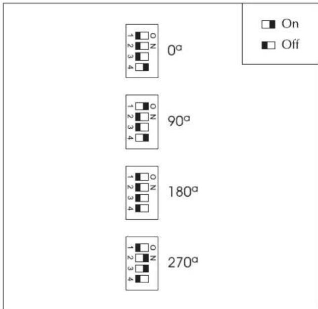
Figure 67. The four setting positions for the phase dip switches.
30 Making It Work Together
Speaker Placement (Fine Tuning)
Toe in the ESL/Transition towers so the listener is looking at the inner 1/3 of the ESL panels. Sitting at the listening position, hold a flashlight under your chin and point it at each speaker. The reflection of the flashlight should be 1/3 of the way out from the inner edge of the panel (see figure 68).
Viewed from the listening position, the 2-inch space between the transition tower and ESL frame should appear the same on both channels (see figure 66). When you are happy with the final placement of the ESL/Transition towers, carefully remove the glider feet and install the ETC spikes.
Hard Sound
If the speaker sounds hard, there are two options:
1 Change the jumpers on the passive high-pass to turn up the lower midrange (see page 26).
2 Try tilting the speaker back (raise the front feet of the unit). The listener should be straight on with the bottom 1/3 of the panel when listening.

Figure 68. Ideal placement of the ESL/Transition towers.
Tweaking the Room
When you are finished setting up the Statement e2, you should turn the unit up very loud and check the room for rattles. If any are found they should be eliminated.
ESL Tower Spike Installation
When you are happy with the placement of the ESL/ transition towers, we recommend that you install the ETC spikes. This procedure requires at least two people—one to tip the tower and one to install the spikes.
1 With one person standing behind the tower carefully tip the tower back.
2 Remove the glider feet and the screw the 2 front spikes into place making sure to thread the large black rubber washer onto the spike post.
3 With one person standing in front of the tower carefully tip the tower forward.
4 Remove the remaining glider foot and the screw the back spikes into place making sure to thread the large black rubber washer onto the spike post.
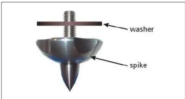
Figure 69. Statement spikes.

MARTIN LOGAN®
the loudspeaker technology company
2101 Delaware Street, Lawrence, Kansas 66046, USA tel 785.749.0133 fax 785.749.5320 www.martinlogan.com
- STATEMENT™ E2 setup manual
- CONTENTS
- Contents 2
- Before You Begin ....3
- Speaker Placement ....4
- Assembly 5
- Connections—Exos Crossover Inputs .....21
- Connections—Exos Crossover Outputs .....22
- Connections—ESL/Transition Towers .....23
- Connections—Subwoofer Towers .....25
- Passive Hi-Pass Settings .....26
- AC Power Connection .....28
- Making It Work Together .....29
- Master Packing List Required Tools
- Sub (Left)
- Sub (Right)
- ESL/Transition Towers
- Base (Left)
- Base (Right)
- EXOS
- Provided (in crate 12):
- You will need to provide:
- Not required, but useful:
- Unpacking the Statement E2
- Initial Speaker Placement The Wall Behind the Listener
- The Wall Behind the Speakers
- The Side Walls
- Subwoofer Tower Assembly
- Transition/Electrostatic Tower Assembly
- CONNECTIONS—EXOS CROSSOVER INPUTS
- Full Range OutputsSubwoofer Outputs
- Bi-Wire Connection
- Horizontal Passive Bi-Amplification
- Vertical Passive Bi-Amplification
- 8-Ohm Connection 4-Ohm/Bi-Amp Connection
- 2-Ohm Connection
- The High-Pass Settings
- 10-Foot Mode (figure 58)
- All-Closed Mode (figure 59)
- All-Open Mode (figure 60)
- 15-Foot Mode (default—(figure 61)
- Note:
- Making It Work Together (Part 1) Setting the Dip Switches
- Subwoofer Level Knob
- How to adjust the dip switches:
- Making It All Work Together (Part 2)
- Speaker Placement (Fine Tuning)
- Hard Sound
- Tweaking the Room
- ESL Tower Spike Installation
Brand : Martin Logan
Model : Statement E2
Category : Speaker