AC MAX Smart 11kW - Car charger DELTA - Free user manual and instructions
Find the device manual for free AC MAX Smart 11kW DELTA in PDF.

| Product Type | Electric Vehicle Charger |
| Brand | Delta |
| Model | AC MAX Smart 11kW |
| Power Output | 11 kW |
| Input Voltage | AC 230V (single phase) |
| Connector Type | Type 2 (Mennekes) |
| Charging Mode | Mode 3 |
| Smart Features | Wi-Fi, Bluetooth, mobile app control |
| Dimensions (H x W x D) | 300 x 200 x 100 mm |
| Weight | 3 kg |
| Protection Features | Overcurrent, overvoltage, surge, ground fault |
| IP Rating | IP54 |
| Cable Length | 5 m |
| Display | LED status indicators |
| Installation | Wall-mounted |
| Standards | IEC 61851-1 |
| Warranty | 2 years |
| Operating Temperature | -30°C to 50°C |
| Energy Meter | Integrated |
| Load Balancing | Dynamic load balancing supported |
Frequently Asked Questions - AC MAX Smart 11kW DELTA
User questions about AC MAX Smart 11kW DELTA
0 question about this device. Answer the ones you know or ask your own.
Ask a new question about this device
Download the instructions for your Car charger in PDF format for free! Find your manual AC MAX Smart 11kW - DELTA and take your electronic device back in hand. On this page are published all the documents necessary for the use of your device. AC MAX Smart 11kW by DELTA.
USER MANUAL AC MAX Smart 11kW DELTA
Installation and operation manual
AC MAX
EU-Smart version
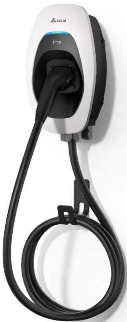
natural_image
White electric vehicle charging station with black cable, no visible text or symbols on bodyTable of Contents
1 Information....3
1.1 Copyright....3
1.2 Intended use 3
1.3 Safety instructions....3
1.4 Operator's duty of supervision .... 4
1.5 Model series....5
1.6 Product overview....6
2 Installation 9
2.1 Preparation before start 9
2.2 Installation steps 11
3 Commissioning....22
3.1 Connection setting 23
3.2 Login 24
3.3 Configuration....25
3.4 Edit password....28
3.5 Maintenance 28
3.6 Forgot password 32
4 Operation....33
4.1 Start charging....33
4.2 Stop charging....33
5 LED Indicator....33
5.1 Fault events 34
5.2 Symbol description....34
6 Troubleshooting....35
7 Specifications 36
8 Cleaning 37
9 Warranty 37
10 Disposal....37
1 Information
1.1 Copyright
The ownership and all intellectual property rights of this Installation and Operation Manual (this "Manual"), including but not limited to the content, data and figures contained herein are vested by Delta Electronics, Inc. ("DELTA"). The Manual can only be applied to operation or use of the device. Any disposition, duplication, dissemination, reproduction, modification, translation, extraction or any other usage to the Manual is prohibited without obtaining DELTA's prior written permission. As the product will be developed and improved continuously, DELTA may modify or update the Manual from time to time without any notice. DELTA disclaims any kinds or forms of warranty, guarantee or undertaking, either expressly or implicitly, including but not limited to the completeness, accuracy, non-infringement, merchantability or fitness for particular purpose or usage. Copyright © 2021 Delta Electronics, Inc. All Rights Reserved.
1.2 Intended use
The device is developed, manufactured, tested and documented according to the safety standards. If you comply with the instructions and safety instructions described for its intended use, the product normally will not pose any danger in terms of property damage or to the health of people. The instructions contained in this manual shall follow to the letter. Otherwise, sources of danger may be produced or safety equipment may be rendered inoperable.
This device may only be used to charge Battery Electric Vehicle or Plug-in Hybrid Electric Vehicle in accordance with the following regulations:
● Mode 3 charging according to IEC 61851-1 for electric vehicles with non-gas discharged batteries.
- Use with plugs and sockets according to IEC 62196.
In addition, the following conditions apply for intended use:
● The device is exclusively for stationary installation.
● The device is designed for installation on a wall or pedestal.
● The device can be used for indoors and outdoors.
The following uses are considered as not intended:
● The charging of electric vehicles with gassing batteries is not permitted.
1.3 Safety instructions
Before installing, commissioning, and operating of the EVSE, review this manual carefully and consult with licensed contractors, licensed electricians and installation experts to ensure compliance with local building practices, climate conditions, safety standards, and state and local codes. DELTA is not responsible for damage caused by failure to follow the safety instructions and work instructions in this manual.

text_image
DANGER
Risk of electric shock
Dangerous voltages and currents can occur during operation of the EVSE. Therefore, before carrying out any work on the EVSE, take the following protective measures:
- Disconnect all electrical power prior to installing the EVSE. Failure to do so may result in electric shock, physical injury or damage to the electrical system and charging unit.
- Do not remove circuit protective devices or any other component until all electrical power is disconnected.
-
Secure the working area against access by unauthorized persons.
-
The EVSE must be connected to a grounded, metal, permanent wiring system or an equipment grounding conductor must be run with the circuit conductors and connected to the equipment grounding terminal or lead on the EVSE.
- Use a measuring instrument to check that there is no voltage.
- Use appropriate protection when connecting to the main power distribution cable.

DANGER
Risk of electric shock
Dangerous voltages and currents can occur when operating the EVSE.
- Do not use the device to charge or supply other devices.
- Do not touch the contact pins of the charging plug when operating.
- Do not use adapters, conversion adapters or cord extension sets with the EVSE.
- Do not use this EVSE if the flexible power cord or charging cable is frayed, the insulation is broken, or the device shows signs of damage.

WARNING
- Close the charging plug with the protective cap when not in use.
● Damaged cables may only be replaced by electricians. - Do not use this EVSE if the enclosure or the vehicle connector is broken, cracked, open, or shows any signs of damage.
- Only pull the charging cable out of the charging socket by the charging plug.

CAUTION

Risk of tripping
People can trip over cables lying around.
▶ Always hang the charging cable in the holder supplied with the EVSE after use.
- A device using pressure connectors for field wiring connections must be supplied with instructions that specify a range or nominal value of the tightening torque to be applied to the terminal screws of the connectors.
- Any repair work as well as the replacement of components on the EVSE may only be carried out by DELTA. Otherwise the warranty will become void.
● Damaged or illegible safety labels must be replaced.
● The EVSE can only be installed by licensed contractors, or licensed electricians in accordance with all applicable state, local and national electrical codes and standards in a location with non-restricted access. - To ensure the ingress protection degree IP55, seal all external connections adequately. Seal unused connections with the caps provided.
- Warning notices, warning symbols and other markings attached to the EVSE by DELTA must not be removed.
1.4 Operator's duty of supervision
● As the operator of the EVSE, you are responsible for the safety of the users and its proper use.
- As the operator of the EVSE, you are responsible for the safety of particularly vulnerable persons, especially children. Ensure that such persons maintain a sufficient safety distance from the EVSE and the charging cable.
- Consider the emergency routes at the installation site.
- Do not install the device at potentially explosive atmosphere areas (Ex areas).
1.5 Model series
The following describes the segmentation used to describe the basic features of each available model:
EIAW - X XXK X X X X X XX
1 2 3 4 5 6 7 8
| Segment | Item | Description |
| 1 | E: AU/NZ, EMEA, SEA,G: ChinaJ: JapanT: TaiwanU: Canada, US | Indicate the available region |
| 2 | From 1-99:7: 7 kW11: 11 kW22: 22 kW | Indicates the nominated maximum output power |
| 3 | S: Single phaseT: Three phase | Indicates the phase of input rating |
| 4 | B: BasicS: SmartP: Premium | Indicates the version of EVSE |
| 5 | U: SAE J1772 plugE: IEC 62196-2 plugS: IEC 62196-2 socketH: IEC 62196-2 shutterG: GB/T 20234.2 plug | Indicates the charging interface |
| 6 | From 1-9:5: 5 m7: 7 m | Indicates the cable length (0 for socket or shutter) |
| 7 | From A-Z:A: Generation AB: Generation B | Indicates the product generation |
| 8 | From 01-99 | Indicates the serial code of EVSE |
1.6 Product overview
1.6.1 Scope of delivery
| Part | Description | Part | Description | |
| EVSE* | 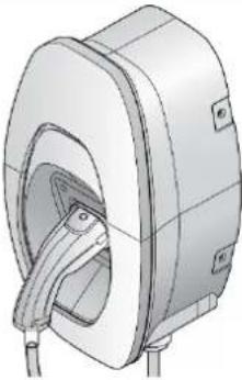 | Mounting bracket |  | |
| 1x | 1x | |||
| Template | 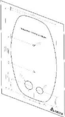 | Torx T30 mounting bolts |  | |
| 1x | 4x | |||
| No. 8 wood screws |  | 1/4 inch expansion bolts |  | |
| 2x | 2x | |||
| Quick installation guide | 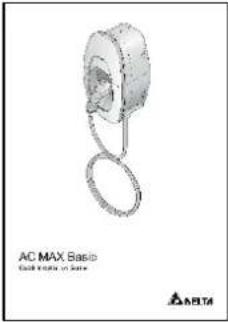 | Safety instructions |  | |
| 1x | 1x | |||
| Cable gland | 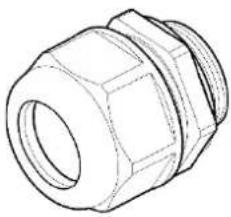 | wood screws |  | |
| 1x | 2x | |||
| Control board | 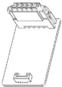 | Cable holder* (For plug version only) | 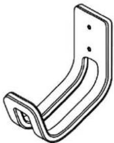 | |
| 1x | 1x | |||
| RFID | 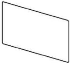 | |||
| 2x | ||||
*Depends on model configuration
1.6.2 Recommended tools
The following tools are recommended for the installation of product:
| Part | Description |
| Electro drill | Used for masonry walls |
| Pencil | |
| Spirit level | |
| Terminal crimper | Crimping input wire |
| Torque wrench | |
| Torque screwdriver (cross) | Securing mounting bracket to masonry walls or stand |
| Torque screwdriver (slotted) | Securing mounting bracket to masonry walls or stand |
| Torx T20 screwdriver | Securing front cover and middle cover |
| Torx T30 screwdriver | Securing mounting bracket |
1.6.3 Installer-supplied components
Installers may prepare the following parts:
- Conduit of appropriate size or cable gland (M32) for input power wires to ensure the water resistance.
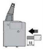
- DIN 46228-4 Cord end terminal:
Please use the cord end terminal for split conductors while installation.
| Current 16 A 32 A | |||
| Pin length | 18 mm | 18 mm | 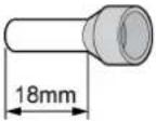 |
| Wire range | 4 mm^2 | 10 mm^2 | |
- Upstream breakers:
To reduce the risk of fire, only connect to a circuit with circuit breaker conforming to IEC 60898-1.
| Model | Circuit breaker specification |
| EIAW-E7K | 40A min., 230V min., 2 poles, Type B |
| EIAW-E11K | 20A min., 400V min., 4 poles, Type B |
| EIAW-E22K | 40A min., 400V min., 4 poles, Type B |
- SIM card:
| SIM card | Width | Height | Depth | 4G support band |
| Micro SIM | 15 mm | 12 mm | 0.76 mm | Band 1, Band 3, Band 7, Band 8, Band 20 |
- Ethernet cable:
| Part | Specification |
| Connector | Modular registered jack 45 (RJ45) |
| Cable | Category 5 (Cat 5), 10/100 Mbps |
1.6.4 Overview of components

- Mounting bracket
- Body
- Middle cover
- LED bar
- Cable gland
- RFID reader
7-A. Vehicle connector
7-B. Socket/ socket with shutter - Front cover
- Water proof cap
2 Installation
Before you start, please read the following instructions:
2.1 Preparation before start
2.1.1 Installation site selection
AC MAX can be installed in both indoor and outdoor environments. It is necessary to consider the installation conditions and protection at the site:
- Follow local electrical regulation and installation standards.
- Consider the emergency routes at the installation site.
- Do not install the device at potentially explosive atmosphere areas (Ex areas).
2.1.2 Recommended installation positions
When considering installation positions, make sure EV can be easily connected with EVSE and have enough space for maintenance.
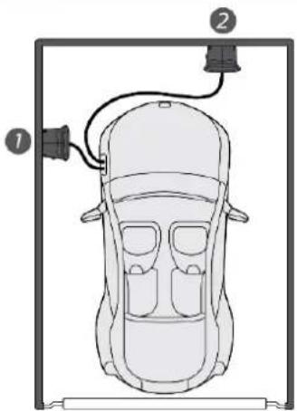
natural_image
Top-down diagram of a car with two labeled parts (1 and 2), showing front and side views without any text or symbols.- Recommended position
- Alternative position
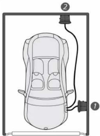
natural_image
Top-down diagram of a car with an attached lamp and cable, no text or symbols present2.1.3 Recommended installation space
Installers shall follow applicable accessibility requirements for the mounting position. The EVSE shall be mounted at a height between 800 mm (31.5 inches) and 1200 mm (47.2 inches) above ground.
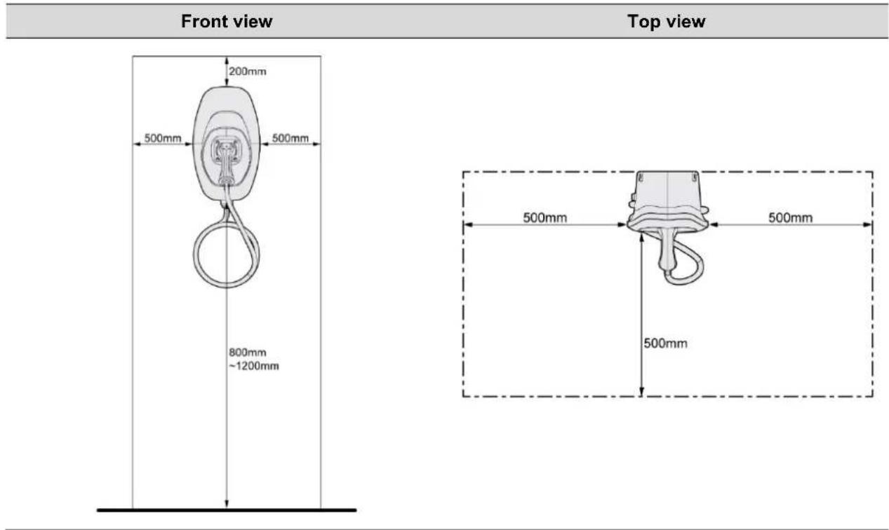
text_image
Front view 200mm 500mm 500mm 800mm ~1200mm Top view 500mm 500mm 500mm 500mm2.2 Installation steps
2.2.1 Remove front cover and middle cover
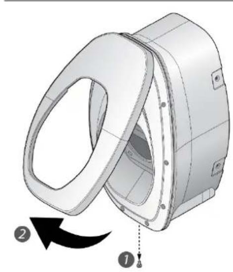
natural_image
3D mechanical component diagram showing a rotating housing with labeled parts (1 and 2), no text or symbols present.- Remove the screw located at the bottom of front cover by using a Torx T20 screwdriver.
- Pull the front cover upward to separate from the EVSE.
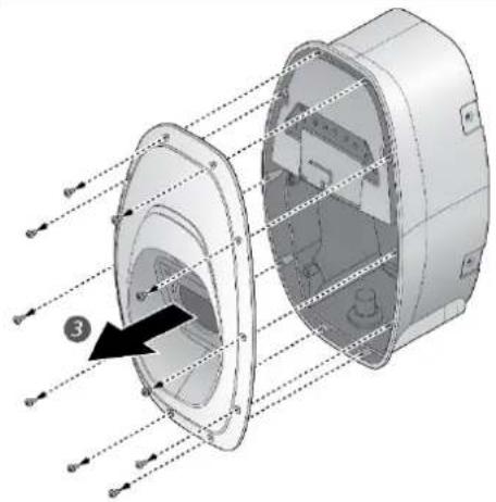
natural_image
3D diagram of a mechanical component with internal structure and directional arrows, no text or symbols present- Remove the screw located at the middle cover by using a Torx T20 screwdriver.
- Remove the middle cover.
2.2.2 (Optional) insert SIM card for cellular function
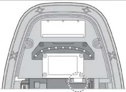
natural_image
Technical diagram of a mechanical component with no visible text or symbolsInsert the SIM card into the socket and ensure the connection is well connected.
2.2.3 Mark drill holes
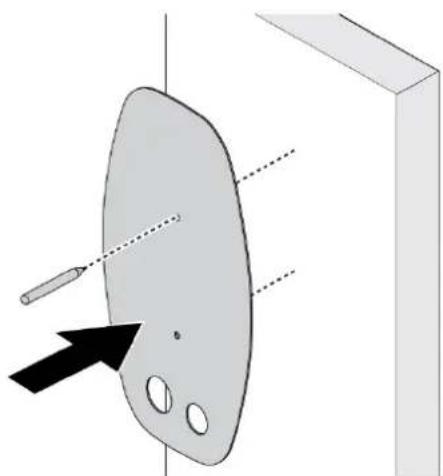
natural_image
Diagram of a 3D object with a pencil and arrow pointing to a surface, no text or symbols presentThe EVSE is a stationary wall-mounted equipment. Using the template to mark the screw locations for the mounting bracket and cable holder (optional).
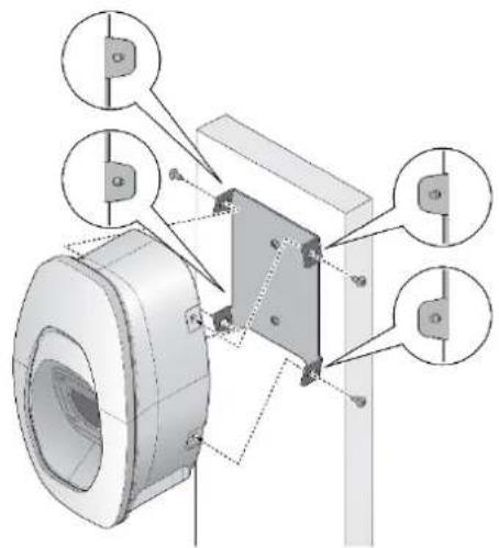
2.2.4 Secure mounting bracket
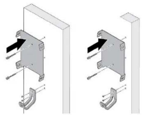
natural_image
Technical illustration of two mechanical bracket assemblies with mounting brackets and fasteners (no text or symbols)- The cable holder is optional and depicted in the figure for demonstration purposes. The following are recommended bolt types:
● Masonry walls: 1/4" expansion bolts.
Torque: 8.8 N·m (78 lb·in)
- Finished walls supported by wood studs: #8 wood screws of 2" or above screw length.
Torque: 3 N·m (26 lb·in)
natural_image
Technical diagram of a mechanical assembly with mounting holes and internal components (no text or labels)-
Align the EVSE with the screw holes on the mounting bracket.
-
Secure the EVSE on the mounting bracket with the supplied Torx T30 screws.
Torque: 1.5 N·m (13 lb·in)
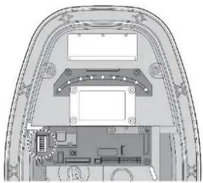
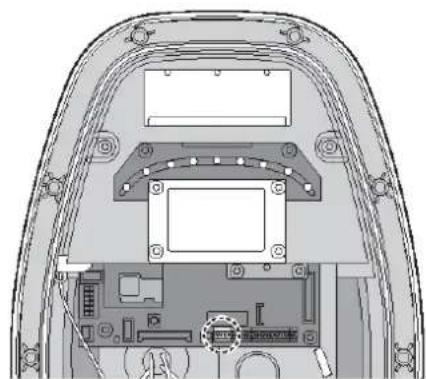
2.2.5 Configure dip switches
natural_image
Technical diagram of a mechanical or electronic component with layered structure and mounting points (no text or symbols)Configure the dip switches with following steps
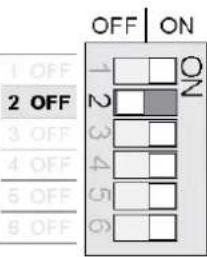
2.2.5.1 Phase unbalance protection
Choose the pin 1 to enable or disable the phase unbalance protection. When the function enabled, the protection will limit the phase unbalance to 15 A.
| Configuration | Function | Configuration | Function | |
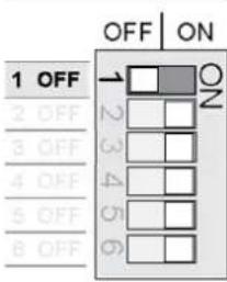 | Disable (Default) | 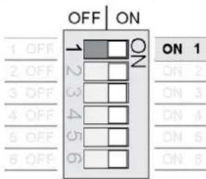 | Enable | |
2.2.5.2 Authorization mode
Choose the pin 2 to configure the authorization mode for bluetooth availability.
| Configuration | Function | Configuration | Function | |
 | ON 1ON 2ON 3ON 4ON 5ON 6 | Not available | 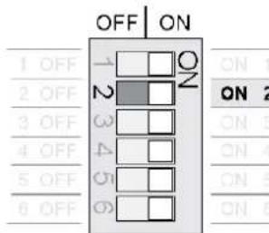 | Bluetooth* (Default) |
*Bluetooth connection is reserved for commissioning purpose.
2.2.5.3 Grounding system
Choose the pin 3 to configure the grounding system for TT/TN or IT system.
| Configuration | Function | Configuration | Function | |
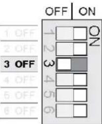 | ON 1 | TT/TN (Default) | 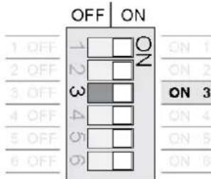 | IT |
| ON 2 | ||||
| ON 3 | ||||
| ON 4 | ||||
| ON 5 | ||||
| ON 6 | ||||
2.2.5.4 Maximum current setting
Choose the pin 4-6 to configure the maximum output current ratings.
| Configuration | Max. Current Ratings | Configuration | Max. Current Ratings |
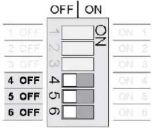 | 6 A (Default) | 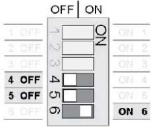 | 16 A |
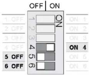 | 8 A | 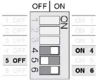 | 20 A* |
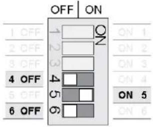 | 10 A | 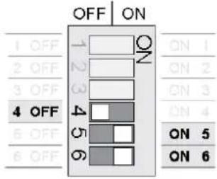 | 24 A* |
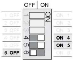 | 12 A | 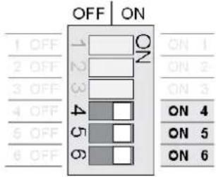 | 32 A* |
*Depends on model configuration
2.2.6 Connect input wire
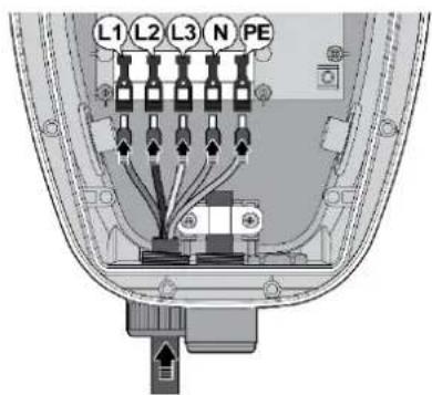
text_image
L1 L2 L3 N PE- Install the copper wire as described. The section of copper wire connected to terminal shall be reserved enough tolerance to prevent any tension or stress from the external force.
Note: Copper wire type: 10 mm ^2 , 70°C.
- Insert the input wire into the terminal accordingly. The cord end terminal shall be inserted to the end without any deviation.
Note: Bottom-fed/rear-fed is available for indoor/outdoor installation with cable gland.
1
2
5
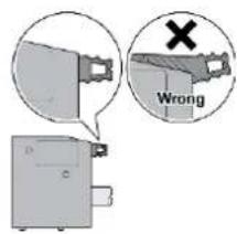
text_image
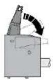
Wrong- Make sure the terminal block is secured correctly.
natural_image
Top-down technical diagram of a device rear view showing internal components and wiring (no text or labels)Dry contact
Use appropriate wires (0.75 mm ^2 ) and connect each of them to the correct terminal connector for dry contact connections shown on wiring schemes (Left 1: NO, Left 2: COM).
Note:
The product provides a closing signal when unable to close the output. There are breaker types that trip to stop output when a closing signal is accepted. It is mandatory requirement for Netherland and Italy.
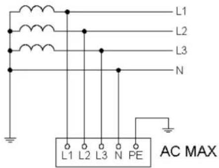
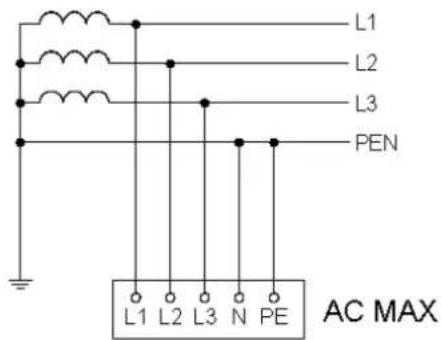
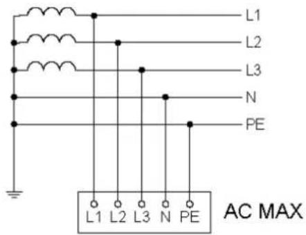
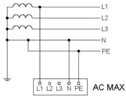
2.2.6.1 Wiring diagram
Single phase Three phase
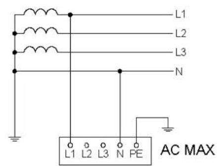
text_image
L1 L2 L3 N L1 L2 L3 N PE AC MAXTT
text_image
L1 L2 L3 N L1 L2 L3 N PE AC MAXTT
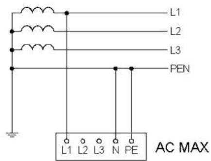
text_image
L1 L2 L3 PEN L1 L2 L3 N PE AC MAXTN-C
text_image
L1 L2 L3 PEN L1 L2 L3 N PE AC MAXTN-C
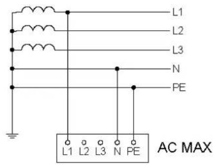
text_image
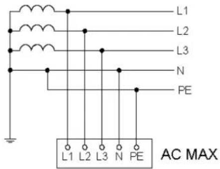
L1 L2 L3 N PE L1 L2 L3 N PE AC MAXTN-S
text_image
L1 L2 L3 N PE L1 L2 L3 N PE AC MAXTN-S
text_image
L1 L2 L3 N PE L1 L2 L3 N PE AC MAXTN-C-S
text_image
L1 L2 L3 N PE L1 L2 L3 N PE AC MAXTN-C-S
Single phase Three phase
text_image
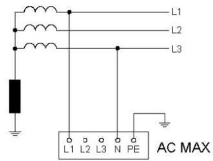
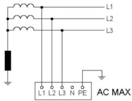
L1 L2 L3 L1 L2 L3 N PE AC MAXIT
text_image
L1 L2 L3 L1 L2 L3 N PE AC MAXIT
Note: To fulfill requirements for electrical installations in UK, the following shall be observed.
- When installed in a TN systems, the supplying circuit shall not include a PEN conductor(combined protective and neutral).
- If the power grid belongs to TN-C-S system, the charger needs to be grounded separately to TT system. A PME earthing facility shall not be used as the means for the protective conductor contact of a charging point located outdoors.
Note: To fulfill requirements for electrical installations in Singapore, the following shall be observed.
- Emergency switching (e.g. emergency button) shall be installed to isolate the a.c. electricity supply (mains) from the EV charging station in case of risk of electric shock, fire or explosion.
2.2.7 (Optional) active power control
Users can control the EVSE with external components (e.g. a ripple control receiver from the power supplier, a domestic controller, a time switch, a combination lock, a photovoltaic system, etc.).
Note:
- Ensure that hazardous voltages are isolated safely.
- The application is taken into consideration for that charging station with a rated power > 12 kVA shall be equipped with control equipment for network integration via an interruptibility by the network operator in Germany.
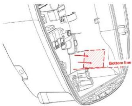
text_image
Bottom line- Based on the bottom line, attach the control board to the inner surface of EVSE.
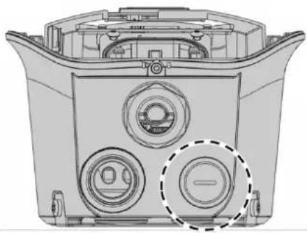
natural_image
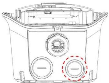
Technical line drawing of a mechanical component with three circular ports and a central hub (no text or symbols)- Remove the water proof cap and pass through the signal cable with appropriate conduit or cable gland.
text_image
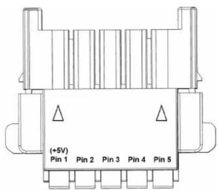
(+5V) Pin 1 Pin 2 Pin 3 Pin 4 Pin 5- Connect the signal cable according to pin definition (2.2.7.1) and must connect to the Pin 1 (+5V).
Note: suggested wire of signal cable: 1.5 mm ^4 .
natural_image
Technical line drawing of a car interior showing engine, battery, and wiring (no text or labels)- Assemble the connector

natural_image
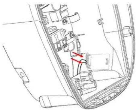
Interior view of a vehicle dashboard with visible wiring and a red directional arrow indicating a component (no text or symbols present)- Connect the control board
2.2.7.1 Pin definition
User can connect the external component with signal cable based on following configuration. The output power will be adjusted by the following pin definition once the grid power is limited by network operator. The power limitation is based on rated output power configured by dip switches (2.2.5.4).
2.2.7.1.1 Configuration A
Connect the signal cable with Pin 1 and Pin 5 as below:
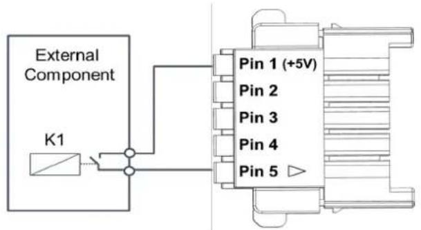
text_image
External Component K1 Pin 1 (+5V) Pin 2 Pin 3 Pin 4 Pin 5| Pin 2 | Pin 3 | Pin 4 | Pin 5 | Power limitation |
| Low | Low | Low | Low | Output 100% power |
| Low | Low | Low | High | Stop charging |
2.2.7.1.2 Configuration B
Connect the signal cable with Pin 1 to Pin 5 as below:
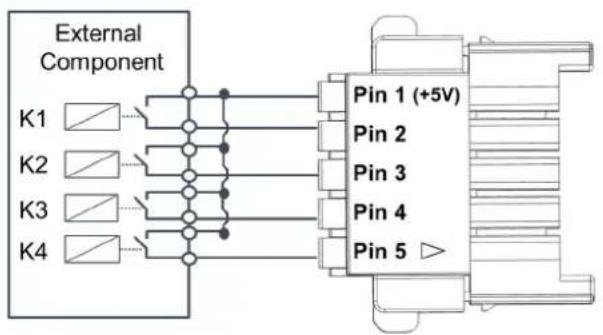
text_image
External Component K1 K2 K3 K4 Pin 1 (+5V) Pin 2 Pin 3 Pin 4 Pin 5 ▶| Pin 2 | Pin 3 | Pin 4 | Pin 5 | Power limitation |
| Low | Low | Low | Low | Output 100% power |
| High | Low | Low | Low | Output 87.5% power |
| Low | High | Low | Low | Output 75% power |
| High | High | Low | Low | Output 62.5% power |
| Low | Low | High | Low | Output 50% power |
| High | Low | High | Low | Output 37.5% power |
| Low | High | High | Low | Output 25% power |
| High | High | High | Low | Output 12.5% power |
| Low | Low | Low | High | Stop charging |
2.2.8 (Optional) connect RJ45 port for Ethernet function
natural_image
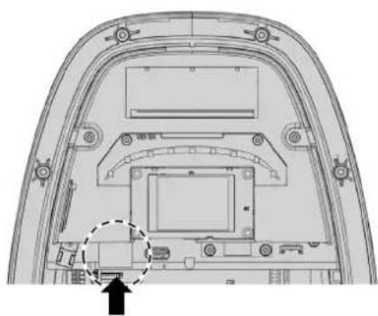
Technical line drawing of a device rear panel with circular components and a dashed circle highlighting one (no text or symbols)- Remove the water proof cap and pass through the Ethernet cable with appropriate conduit or cable gland.
natural_image
Technical line drawing of a mechanical component with no visible text or symbols- Connect the Ethernet cable into the RJ45 port.
2.2.9 Secure middle cover and front cover
natural_image
3D diagram of a mechanical component with internal structure and dimension lines (no text or symbols)- Recover the middle cover on the EVSE and secure the middle cover by using Torx T20 screwdriver.
Torque: 1.2 N·m (10.5 lb·in)
Note: rubber sealing shall be put on the appropriate position before recovery.
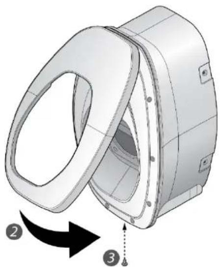
natural_image
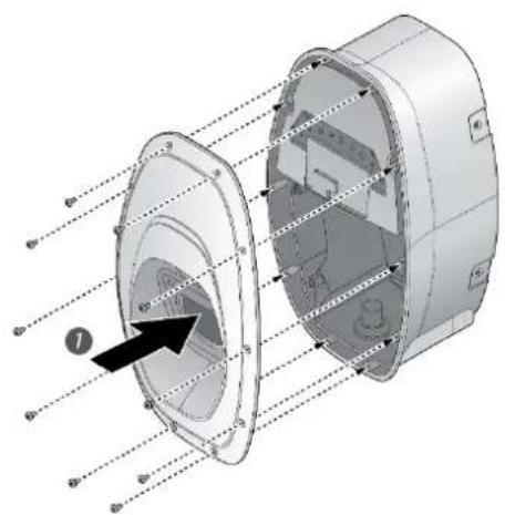
3D mechanical component diagram showing a flanged housing with internal components and directional arrows (no text or symbols)-
Recover the front cover on the EVSE.
-
Secure the screw located at the bottom of front cover by using a Torx T20 screwdriver.
Torque: 0.5 N·m (4.4 lb·in)
3 Commissioning
AC MAX can use the Web Configuration Tool to do the configuration, firmware upgrade, log download, etc. General process:
- Finish the installation process and power on the EVSE.
- Connect to the EVSE with your Laptop or smart phone. If using the Ethernet connection, please finish the connection during installation process.
- Configure the EVSE based on following instruction, and click the button "Save and Restart Charger" if needed.
- Start to charge your EV with operating instruction.
3.1 Connection setting
3.1.1 Through "Ethernet" connection
- Click network icon 📋 in the Taskbar. Open “network and internet setting” and choose the connected network.
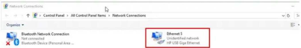
text_image
Network Connections Control Panel > All Control Panel Items > Network Connections Organize Bluetooth Network Connection Net connected Bluetooth Device (Personal Area ... Ethernet 5 Unidentified network HP USB Giga Ethernet- Choose TCP/IPv4 and enter the IP address
IP address: 192.168.123.101
Subnet mask: 255.255.255.0
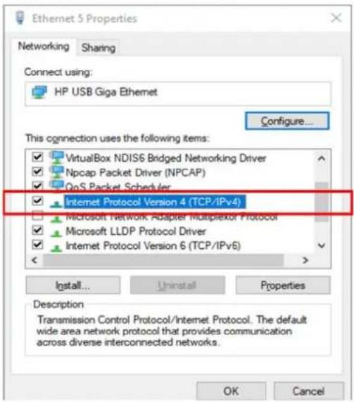
text_image
Ethernet 5 Properties Networking Sharing Connect using: HP USB Giga Ethernet Configure... This connection uses the following items: VirtualBox NDIS6 Bridged Networking Driver Npcap Packet Driver (NPCAP) QoS Packet Scheduler Internet Protocol Version 4 (TCP/IPv4) Microsoft Network Adapter Multiplexor Protocol Microsoft LLDP Protocol Driver Internet Protocol Version 6 (TCP/IPv6) Install... Uninstall Properties Description Transmission Control Protocol/Internet Protocol. The default wide area network protocol that provides communication across diverse interconnected networks. OK Cancel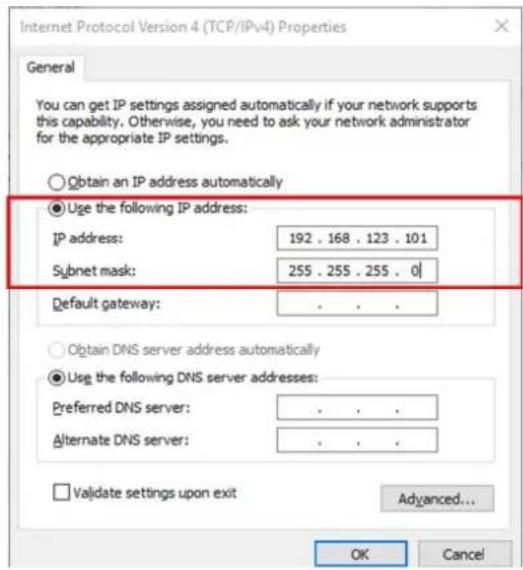
text_image
Internet Protocol Version 4 (TCP/IPv4) Properties General You can get IP settings assigned automatically if your network supports this capability. Otherwise, you need to ask your network administrator for the appropriate IP settings. Obtain an IP address automatically Use the following IP address: IP address: 192 . 168 . 123 . 101 Subnet mask: 255 . 255 . 255 . 0 Default gateway: . Obtain DNS server address automatically Use the following DNS server addresses: Preferred DNS server: . Alternate DNS server: . Validate settings upon exit Advanced... OK Cancel3.1.2 Through "Wifi" connection
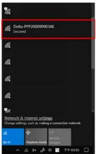
- Click network icon in the Taskbar. Open "network and internet setting" and choose the connected network.(SSID: Delta-serial number/ Password: please refer to the last page of "Quick Installation Guide")
text_image
Delta-PPP200099903AE Secured Network & Internet settings Change settings, such as making a connection metered. Wi-Fi Airplane mode Mobile Hotspot 03:55Note: serial number refers to the spec label on EVSE.
3.2 Login
- Open web browser.
Note: recommended web browser includes Chrome 67 and above, safari 11 and above, IE 10 and above, Firefox 61 and above.
- Enter the web address and login.
Default web address: 192.168.123.123 (Ethernet)/ 192.168.5.1(WiFi)
User account: admin
Password: please refer to the last page of "Quick Installation Guide"

text_image
C ▲ 不安全 | 192.168.123.123
DELTA
Smarter, Greener, Together.
Web Configuration Tool

insignat © 2021 Data Technologies, Inc.
All rights reserved.
Note: "Failed login attempts" is allowed 5 times and the account will be locked afterwards. User can try it again after 5 minutes.
- After login, user can see the "Home" page and EVSE information.

text_image
Home 不安全 | 192.168.123.123/home.php NELTA Home Configuration Edit Password Maintenance Sign outInformation
natural_image
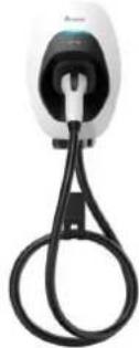
White electric vehicle charging plug with black cord and cable (no visible text or symbols)Model Name: EIAW-
Serial Number: PPP200099903AE
Ethernet MAC address: 90:9a:77:6a:25:e8
WiFi MAC address : d4:ca:6e:9a:14:d7
MPU Firmware version: 01.24.00.02
WiFi Signal Strength: -50 dBm
Cellular Signal Strength: 0 dBm
Error Code: 0
copyright © 2021 Delta Electronics, Inc. All rights reserved.
3.3 Configuration
3.3.1 Operating without OCPP system
User can configure the below information for EVSE:
| Item | Description |
| Authentication | Choose the authorized mode for user authentication. Default will be “RFID mode”. |
| Maximum charging time | Choose the maximum charging time for each charging session. Default will be “No limit”. |
| Maximum charging current | Choose the maximum charging current per phase. It is limited by the dip switch setting. |
| System time | Choose the system time “YYYY/MM/DD- HH:MM:SS” |
| Wifi AP mode | When active, EVSE is capable of commissioning through wifi connection directly. |
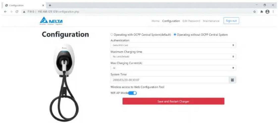
text_image
Configuration ELTA DELTA Configuration Home Configuration Edit Password Maintenance Sign out Operating with OCPP Central System(default) Operating without OCPP Central System Authentication Delta RMS Card Maximum Charging time No Limit(Default) Max Charging Current(A) 32 System Time 2000/03/20-00:30:07 Wireless access to Web Configuration Tool WiFi AP Mode Save and Restart Charger3.3.2 Operating with OCPP system
User can configure the below information for EVSE:
| Item | Description |
| Charge Box ID | The Box ID shall be consistent with the one in your OCPP system. |
| Server URL | Enter the URL to connect to your OCPP system |
| OCPP version | Choose OCPP version. Default will be “OCPP 1.6J”. |
| Offline policy | Choose the behavior when disconnection. Default will be “Local authentication”. |
| Maximum charging current | Choose the maximum charging current per phase. It is limited by the dip switch setting. |
| System time | Choose the system time “YYYY/MM/DD- HH:MM:SS” |
| Wifi AP mode | When active, EVSE is capable of commissioning through wifi connection directly. |
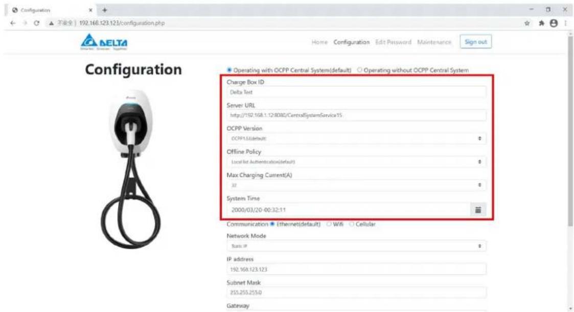
text_image
Configuration 192.168.123.123/configuration.php Home Configuration Edit Password Maintenance Sign out Operating with OCPP Central System(default) Operating without OCPP Central System Charge Box ID Delta Text Server URL http://192.168.1.12:8080/ControlSystemService15 OCPP Version OCPP1.6(default) Offline Policy Local Net Authentication(default) Max Charging Current(A) 32 System Time 2000/03/20-00:32:11 Communication Ethernet(default) WiFi Cellular Network Mode Basic IP IP address 192.168.123.123 Subnet Mask 255.255.255.0 GatewayFor communication setting, please refer to below section. Users are able to connect the OCPP system through either "Ethernet", "Wifi", or "Cellular" connection.
3.3.2.1 Connection through "Ethernet"
Choose the "Network mode", and enter the corresponding information.
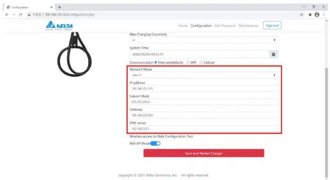
text_image
Configuration 192.168.123.123/configuration.php Max Charging Current(A) 32 System Time 2000/03/20-00:32:11 Communication ● Ethernet(default) ○ WiFi ○ Cellular Network Mode State IP IP address 192.168.123.123 Subnet Mask 255.255.255.0 Gateway 192.168.123.254 DNS server 192.168.123.1 Wireless access to Web Configuration Tool WiFi AP Mode Save and Restart Charger copyright © 2021 Delta Electronics, Inc. All rights reserved.3.3.2.2 Connection through "Wifi"
Enter the information based on your wireless AP setting.
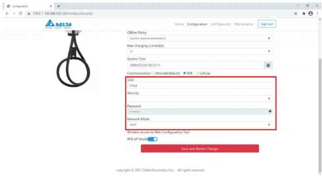
text_image
Configuration 192.168.123.123/configuration.php Home Configuration Edit Password Maintenance Sign out Offline Policy Local for Authentication(default) $ Max Charging Current(A) 32 $ System Time 2000/03/20-00:32:11 Communication ○ Ethernet(default) ● WiFi ○ Cellular SSID STTest Security Password ****** Network Mode DHCP Wireless access to Web Configuration Tool WiFi AP Mode Save and Restart Charger copyright © 2021 Delta Electronics, Inc. All rights reserved.3.3.2.3 Connection through "Cellular"
Enter the information based on your contract with telecom operator.
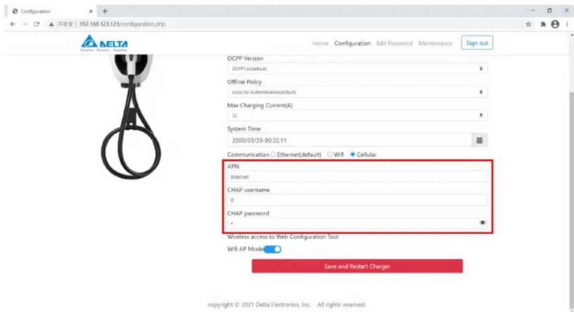
text_image
Configuration 不安全 | 192.168.123.123/configuration.php Home Configuration Edit Password Maintenance Sign out OCPP Version OCPP1.0(default) Offline Policy Local lat Authentication(default) Max Charging Current(A) 32 System Time 2000/03/20-00:32:11 Communication ○ Ethernet(default) ○ WiFi ● Cellular APN Internet CHAP username 0 CHAP password ● Wireless access to Web Configuration Tool WiFi AP Mode Save and Restart Charger copyright © 2021 Delta Electronics, Inc. All rights reserved.v1.0.2
3.4 Edit password
User can find default password on quick installation guide, and use it for the setting of new password.
3.5 Maintenance
To get the better charging experience, users are recommended to do the maintenance with following instruction:
Item Description
Firmware update User can get the latest or improved function through firmware update, and please contact the local dealer or DELTA service partner for the support.
Log download User can download the log file to analyze the EVSE status.
Factory reset User can reset the EVSE to default setting.
text_image
Maintenance 192.168.123.123/maintenance.php Home Configuration Edit Password Maintenance Sign out Maintenance Firmware Upgrade (to be performed by trained technician only) Browser File(s) Log Download Log Download Factory Reset Restore passwords to default values and clear all charging profile copyright © 2021 Delta Electronics, Inc. All rights reserved.2. Choose the correct path and file to upload.
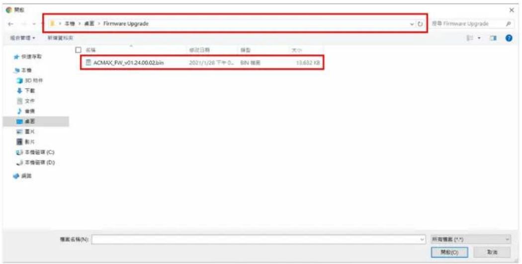
Note: please contact the local dealer or DELTA service partner for the latest firmware file.
- Press the button "Upload and restart charger" to start uploading.

text_image
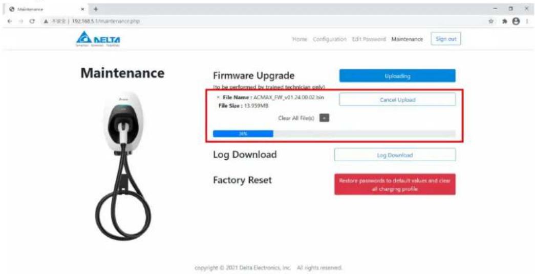
Maintenance 192.168.5.1/maintenance.php Home Configuration Edit Password Maintenance Sign out Maintenance Firmware Upgrade (to be performed by trained technicians only) • File Name : ACMAX_FW_v01.24.00.02.bin File Size : 13.959MB Clear All Files) Browser File(s) Upload and Restart Charger Log Download Log Download Factory Reset Restore passwords to default values and clear all charging profile copyright © 2021 Delta Electronics, Inc. All rights reserved.- Uploading the file.
text_image
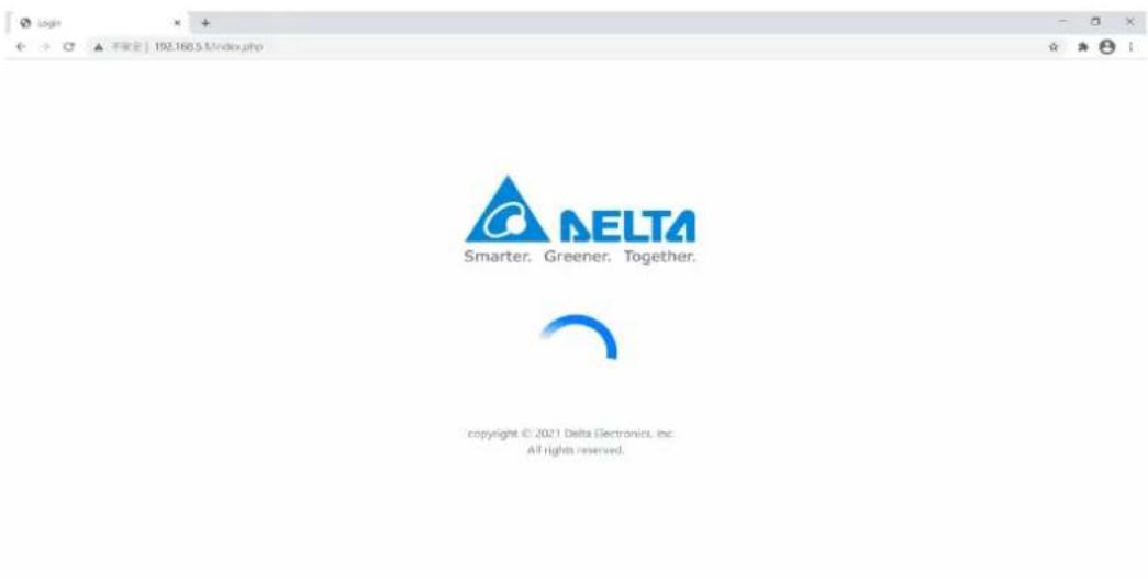
Maintenance 192.168.5.1/maintenance.php Home Configuration Edit Password Maintenance Sign out Maintenance Firmware Upgrade (to be performed by trained technician only) File Name : ACMAX_FW_v01.24.00.02 bin File Size : 13.959MB Clear All File(s) - 34% Uploading Cancel Upload Log Download Log Download Factory Reset Restore passwords to default values and clear all charging profile. copyright © 2021 Delta Electronics, Inc. All rights reserved.- After uploading, EVSE will restart automatically.
text_image
ALTA Smarter. Greener. Together. copyright © 2021 Delta Electronics, Inc. All rights reserved.v1.0.2
Log download
Press the button "Log download" to get the log file.
Note: user may describe your question and copy the file when contacting the local dealer or DELTA service partner.
Factory reset
User can restore the EVSE to factory setting by pressing the button "Restore passwords to default values and clear all charging profile".
3.6 Forgot password
If user forgot the password, please follow below to recover.
- Click the "Forgot Password?".

text_image
login + ← → ▲ 不安全 | 192.158.123.123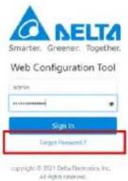
text_image
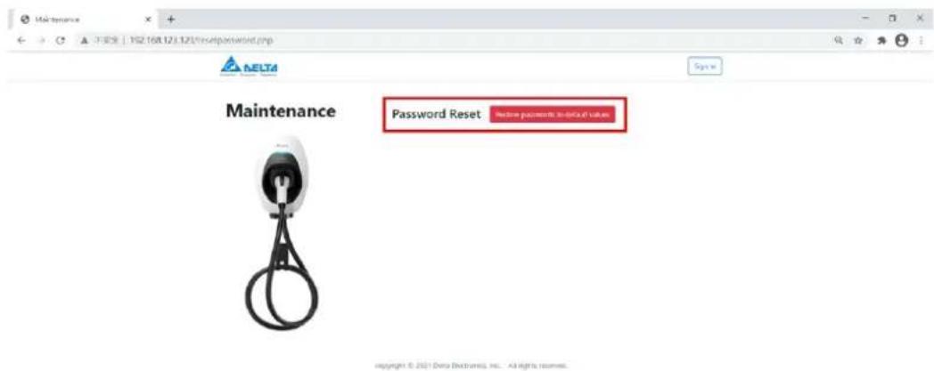
NELTA Smarter, Greener, Together. Web Configuration Tool login Sign In Target Password ? copyright © 2021 Delta Electronics, Inc. All rights reserved.- Click the button "Restore passwords to default values"
text_image
Maintenance Password Reset Below passwords to default value Copyright © 2017 Delta Diagnostics, Inc. All rights reserved.- Confirm if the user want to reset the password. After clicking the button "Yes", the EVSE will restart automatically.
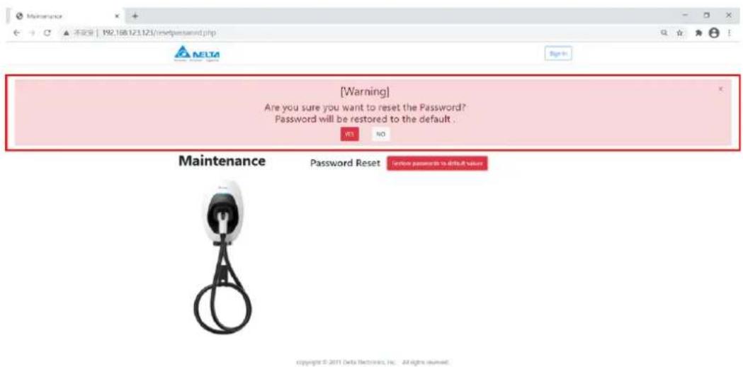
text_image
[Warning] Are you sure you want to reset the Password? Password will be restored to the default . NO Maintenance Password Reset I notice passwords to default value Copyright © 2011 Delta Electronics, Inc. All rights reserved.4 Operation
Turn on the upstream breaker. The indicator flashes in yellow during a system self-test. After the self-test completed, the indicator illuminates in blue and the EVSE is ready to charge.
4.1 Start charging
- Connect the vehicle connector to vehicle inlet.
Note: for socket or socket with shutter model, please connect the plug to EVSE first.
- Place the RFID card over the sensor area to initiate the charging process.
Note:
a. Successful card detection is indicated by two short beeps. A long beeping sound indicates authentication failure. Please check your card and try it again.
b. The EVSE returns to standby mode if the vehicle connector is not connected to the EV within 60 seconds after card authentication.
- The indicator flashes blue to indicate the charging is initiated.
4.2 Stop charging
- Stop charging session at the vehicle or swipe the RFID card again to stop the charging process.
- Disconnect the vehicle connector from the vehicle inlet.
Note: the plug would be locked by the EV and please unlock the plug if needed.
- Recover the vehicle connector to vehicle connector inlet.
5 LED Indicator
| Status Description | |
| Black Power off. | |
| Yellow, fast flashing | Initial configuration and self-test |
| Blue Standby mode (not connecting to EV). | |
| Yellow Ready to charge (connecting to EV). | |
| Blue, slow flashing Charging in progress. | |
| Green | Charging process completed or network connection success. |
| Yellow, 1 Flash | Network connection fail. |
| Yellow, slow flashing | Limited output power by active power control or OCPP command, firmware upgrade or log download. |
| Red, slow flashing Refer to fault event. | |
| Red | Failed self-test or general malfunction. |
5.1 Fault events
| Status Description Action | ||
| Red, 1 Flash | High/under voltage protection | The EVSE will be auto-recovery once the voltage is normal. If not, please restart the EVSE or contact customer support. |
| Red, 2 Flashes | Ground fault protection. | Check the ground system, and wait for recovery. |
| Red, 3 Flashes | Ground does not correctly connect to the EVSE. | Check if ground (PE) is well connected. |
| Red, 4 Flashes | Over current protection. | Unplug the vehicle connector and plug it again. |
| Red, 5 Flashes | Over temperature protection. | Wait for recovery and check if any heat source around the EVSE. If yes, please try to remove the heat source. |
| Red, 6 Flashes | Input mis-wired. | Swap the Line (L) and Neutral (N). |
| Red, 7 Flashes | Control pilot signal error, Gun lock error/fault | Unplug the vehicle connector and plug it again. If not recovery, please contact customer support. |
5.2 Symbol description
| Status Description | |
| Slow flashing | Slow flashing (period = 2 s, duty cycle = 50%) |
| Fast flashing | Fast flashing (period = 0.8 s, duty cycle = 50%) |
| 1 Flash | 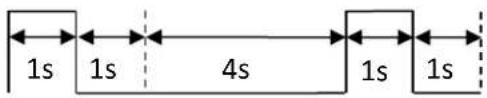 |
| 2 Flashes | 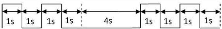 |
| 3 or more Flashes refer to previous figures of time duration. | |
6 Troubleshooting
Contact Customer Support if the EVSE appears to malfunction or if the LED indicators display a fault event. DO NOT open the EVSE, touch or remove the circuit protective devices or any other component.
| Situation Action | |
| Indicator does not light | 1. Make sure the power input is connected correctly and the power is within operating range of the unit.2. Power cycle the EVSE.3. If the problem persists, contact customer support. |
| Indicator does not flash after plugging vehicle connector | 1. Check if the vehicle connector is fully inserted to EV2. Check if the battery is full on EV3. If the problem persists, contact customer support. |
| Indicator starts to flash in red while charging | 1. Wait until the temporary error is resolved and the EVSE returns to normal condition, typically less than 10 seconds.2. Unplug the vehicle connector.3. Power cycle the EVSE.4. If the situation persists, contact customer support. |
| Indicator illuminates in red | 1. It might be a critical error (e.g. hardware fault).2. Unplug the vehicle connector.3. Power cycle the EVSE.4. If the situation persists, contact customer support. |
7 Specifications
| Version | Smart |
| Charging mode | Mode 3 |
| Charging interface | IEC 62196-2: Type 1 plug, Type 2 plug, Type 2 socket, or Type 2 socket with shutter |
| Input/output rating | 220-240 Vac, single phase, 16 A or 32 A max., 50-60 Hz |
| 380-415 Vac, three phase, 16 A or 32 A max., 50-60 Hz | |
| Input wiring | Single phase: L1, N, PE |
| Three phase: L1, L2, L3, N, PE/ L1, L2, L3, PE (IT) | |
| Grounding system | TT/TN/IT |
| Standby power | < 5 W* |
| Altitude | 2000 m |
| Internal residual current detection | AC 30 mA, DC 6 mA(Follow IEC 62955 regulation "provided the automatic test function is performed at every switch on and at intervals once a day") |
| Surge protection | Class II |
| Electrical protection | Over current protection, short circuit protection, over voltage protection, under voltage protection, ground fault protection, surge protection, over temperature protection |
| Cold load pick-up | Randomized delay between 5 and 100 seconds before the charge resume after power outages. |
| Status indicators | Blue, green, red, yellow |
| Network interface | Bluetooth, Ethernet, wifi or cellular |
| Charging protocol | OCPP 1.6J |
| Card reader | RFID card reader compliant to ISO/IEC 14443 A/B |
| Operating temperature | -30°C to +50°C (-22°F to +122°F) |
| Storage temperature | -40°C to +80°C (-40°F to +176°F) |
| Relative humidity | < 95%, non-condensing |
| Length of charging cable | 5 m, straight cable |
| Ingress protection | IP55 |
| Impact protection | IK09 |
| Cooling | Natural cooling |
| Dimension (H x W x D) | 371 x 218 x 167 mm (14.6 x 8.6 x 6.6 inch), excluding charging cable, mounting bracket and cable holder |
| Net weight | 3.9 kg* |
| Compliance/ certificate | CE, UKCA |
*Depends on model configuration
8 Cleaning
Regular cleaning of EVSE is required while standby state. Using a soft damp cloth with clear water is highly recommended and make sure no water enters the vehicle connector.
9 Warranty
Customer service can provide more information on the terms of warranty. However, the following cases are not covered by the warranty.
● Defects or damage caused by not using the product as specified in the Installation and Operation Manual.
● Costs and damage caused by repair work which is not provided by DELTA approved authorized specialist or electrician.
10 Disposal

text_image
Image showing a recycling symbol and a crossed-out trash bin with a horizontal line below it.The EVSE is an electronic device and must be disposed of separately from normal house wastes. Please have it disposed in compliance with the waste disposal and recycle local regulation.