95-9015HG - Kit de montage automobile Metra - Free user manual and instructions
Find the device manual for free 95-9015HG Metra in PDF.


| Product Type | Car Stereo Installation Kit |
| Brand | Metra |
| Model | 95-9015HG |
| Compatible Vehicles | Select Honda and Acura models (1990s-2000s) |
| Material | High-grade ABS plastic |
| Color | Black or Gray (matches OEM interior) |
| Dimensions (Kit) | Approx. 7 x 4.5 x 2 inches (178 x 114 x 51 mm) |
| Weight | Approx. 0.5 lbs (227 g) |
| Power Supply | Not required (passive installation kit) |
| Main Functions | Mounts aftermarket single-DIN or double-DIN radio into factory dash opening |
| Included Components | Dash kit, mounting brackets, screws, wiring harness adapter (if applicable) |
| Installation Difficulty | Easy to moderate (DIY) |
| Tools Required | Trim removal tools, screwdriver, socket set |
| Special Features | Painted to match OEM texture; includes pocket for storage if no radio installed |
| Safety | Complies with automotive interior safety standards |
| Maintenance and Cleaning | Wipe with damp cloth; avoid abrasive cleaners |
| Spare Parts and Repairability | Individual parts not sold separately; replace entire kit if damaged |
| General Information | Designed for easy integration of aftermarket stereos without cutting or modifying dash |
Frequently Asked Questions - 95-9015HG Metra
User questions about 95-9015HG Metra
0 question about this device. Answer the ones you know or ask your own.
Ask a new question about this device
Download the instructions for your Kit de montage automobile in PDF format for free! Find your manual 95-9015HG - Metra and take your electronic device back in hand. On this page are published all the documents necessary for the use of your device. 95-9015HG by Metra.
USER MANUAL 95-9015HG Metra
Volkswagen Touareg 2011-2014
Visit MetraOnline.com for more detailed information about the product and up-to-date vehicle specific applications
KIT FEATURES
• ISO DDIN radio provision
- Painted high gloss black
KIT COMPONENTS
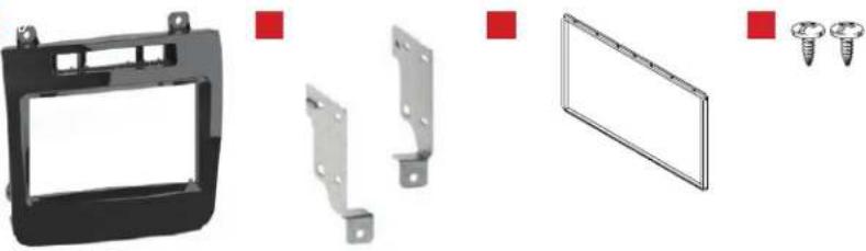
• A) Radio bezel • B) Radio brackets • C) ISO DDIN trim ring • D) Phillips screws (2)
AB
natural_image
Product assembly diagram showing a black plastic frame, metal brackets, and screw fasteners (no text or symbols)TABLE OF CONTENTS
Dash Disassembly 2
Kit Preparation 3
Kit Assembly 3
WIRING & ANTENNA CONNECTIONS (sold separately)
Wiring Harness: Visit axxessinterfaces.com
for wiring harness options
Antenna Adapter: 40-EU56 • 40-EU10 (NAV models)
TOOLS REQUIRED
• 1/8" drill bit • Panel removal tool
• Phillips screwdriver • T-27 Torx screwdriver
• VW radio removal tool (Metra part #86-9001)
Attention! Let the vehicle sit with the key out of the ignition for a few minutes before removing the factory radio. When testing the aftermarket equipment, ensure that all factory equipment is connected before cycling the key to ignition.
DASH DISASSEMBLY
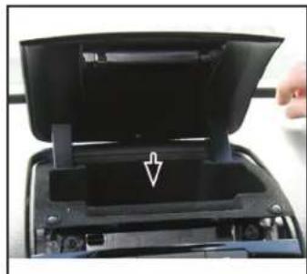
- Open the storage compartment on top of the dash. Remove (1) T-27 Torx screw exposed, then unclip and remove the compartment. (Figure A)
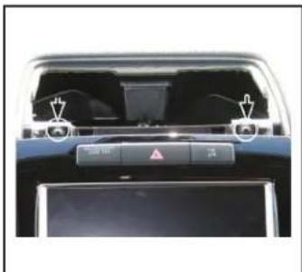
Note: The screw is plastic and attached to a release clip. Once unscrewed, pull the clip out. - Remove (2) T-27 Torx screws securing the top of the radio. (Figure B)
- Using a panel removal tool, carefully pry out the two outermost radio buttons:
With NAV: BAND / TRAFFIC
Without NAV: BAND / CLIMATE
- Using VW radio removal keys (sold separately), release the radio. Slide the radio out, then unplug and remove.
Continue to Kit Preparation
natural_image
Close-up of a black open device with an arrow pointing to the internal component (no visible text or symbols)(Figure A)
natural_image
Interior view of a car dashboard with illuminated screens and control buttons (no visible text or symbols)(Figure B)
KIT PREPARATION KIT ASSEMB
- Push the hazard switch panel, from behind, out of the radio panel.
- Push the hazard switch panel into the 95-9015HG radio bezel until it clicks in.
Continue to Kit Assembly
- Secure the radio brackets to the radio using screws supplied with the radio.
- Locate the factory wiring harness and antenna connector in the dash and complete all necessary connections to the radio. Metra recommends using the proper mating adapter from Metra and/or Axxess. Test the radio for proper operation
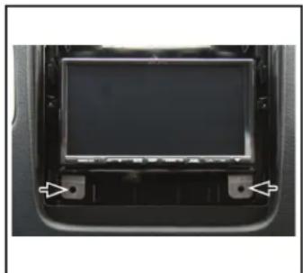
- Slide the radio into the dash, then drill a 1/8" pilot hole in the dash at the (2) radio bracket locations. Secure the radio to the dash using (2) Phillips screws provided. (Figure A)
- Connect the hazard switch panel to the vehicle, then clip the radio bezel to the dash. Secure using the factory screws.
Note: An ISO DDIN trim plate is provided for smaller nose radios which produce a gap around the radio.
- Reinstall the storage pocket in reverse order of disassembly to complete the installation.
natural_image
Interior view of a car dashboard with a black screen and two white arrows pointing to the front panel (no text or symbols visible)(Figure A)
Having difficulties? We're here to help.

our Tech Support line at:
386-257-1187

mail at:
techsupport@metra-autosound.com
Tech Support Hours (Eastern Standard Time)
Monday - Friday: 9:00 AM - 7:00 PM
Saturday: 10:00 AM - 7:00 PM
Sunday: 10:00 AM - 4:00 PM

KNOWLEDGE IS POWER
Enhance your installation and fabrication skills b enselling in the most recognized and respected
mobile electronics school in our industry.
Log onto www.installerinstitute.com or call
600-354-8782 for more information and take steps toward a better tomorrow.

Metra recommends MECP certified technicians
Brand : Metra
Model : 95-9015HG
Category : Kit de montage automobile