
P 8015S - Subwoofer RCF - Free user manual and instructions
Find the device manual for free P 8015S RCF in PDF.


| Type | Passive Subwoofer |
| Woofer Size | 15 inches |
| Power Handling (Program) | 800 W |
| Impedance | 4 ohms |
| Frequency Response | 40 Hz – 120 Hz |
| Sensitivity | 98 dB SPL (1W/1m) |
| Maximum SPL | 128 dB |
| Crossover Frequency | 80 Hz – 120 Hz (recommended) |
| Connectors | 2 x Speakon NL4 |
| Enclosure Material | 15 mm birch plywood |
| Finish | Black textured paint |
| Grille | Steel with acoustic cloth |
| Dimensions (W x H x D) | 480 x 580 x 500 mm |
| Net Weight | 31.5 kg |
| Power Supply | None (passive) |
| Amplification | External amplifier required |
| Protection Features | Overload protection via external DSP |
| Mounting | Pole mount socket (35mm) |
| Intended Use | Live sound, PA systems |
| Cleaning Instructions | Wipe with a dry cloth; do not use solvents |
| Safety | Ensure stable placement; use proper rigging if flown |
| Spare Parts | Contact RCF service centers |
| Repairability | Professional repair only |
Frequently Asked Questions - P 8015S RCF
User questions about P 8015S RCF
0 question about this device. Answer the ones you know or ask your own.
Ask a new question about this device
Download the instructions for your Subwoofer in PDF format for free! Find your manual P 8015S - RCF and take your electronic device back in hand. On this page are published all the documents necessary for the use of your device. P 8015S by RCF.
USER MANUAL P 8015S RCF
OWNER MANUAL MANUALE D'USO
P 8015-S
- P SERIES SUBWOOFER
- SUBWOOFER - SERIE P
INDEX INDICE

ENGLISH
SAFETY PRECAUTIONS 4
DESCRIPTION 6
INSTALLATION NOTES 6
SEALED OR BASS-REFLEX 6
SINGLE LOUDSPEAKER INSTALLATION 7
ARRAY / CLUSTER INSTALLATION 8
CONNECTIONS 13
SPECIFICATIONS 15
ITALIANO
AVVERTENZE PER LA SICUREZZA 16
DESCRIZIONE 18
Before connecting and using this product, please read this instruction manual carefully and keep it on hand for future reference. This manual is to be considered an integral part of this product and must accompany it when it changes ownership as a reference for correct installation and use as well as for the safety precautions.
RCF S.p.A. will not assume any responsibility for the incorrect installation and / or use of this product.
WARNING: To prevent the risk of fire or electric shock, never expose this loudspeaker to rain or humidity and also dust, but the case its reflex ports have been closed by using the respective plugs, in order to get the IP 55 protection grade.
SAFETY PRECAUTIONS
- All the precautions, in particular the safety ones, must be read with special attention, as they provide important information.
- Loudspeaker lines (amplifier outputs) can have a sufficiently high voltage to involve a risk of electrocution: never install or connect this loudspeaker when amplifiers are switched on.
- Make sure all connections have been made correctly and the loudspeaker input impedance is suitable for the amplifier output.
- Protect loudspeaker lines from damage; make sure they are positioned in a way that they cannot be stepped on or crushed by objects.
- Make sure that no objects or liquids can get into this product, as this may cause a short circuit.
- Never attempt to carry out any operations, modifications or repairs that are not expressly described in this manual.
Contact your authorized service centre or qualified personnel should any of the following occur:
- The loudspeaker does not function (or works in an anomalous way).
- The cable has been damaged.
- Objects or liquids are inside the loudspeaker.
-
The loudspeaker has been damaged due to heavy impacts or fire.
-
Should the loudspeaker emit any strange odours or smoke, remove it from the line after having immediately switched the amplifier off.
-
Do not connect this product to any equipment or accessories not foreseen.
For suspended installation, only use the dedicated anchoring points and do not try to hang this loudspeaker by using elements that are unsuitable or not specific for this purpose.
Also check the suitability of the support surface to which the product is anchored (wall, ceiling, structure, etc.), and the components used for attachment (screw anchors, screws, brackets not supplied by RCF etc.), which must guarantee the security of the system / installation over time, also considering, for example, the mechanical vibrations normally generated by transducers.
- RCF S.p.A. strongly recommends this product is only installed by professional qualified installers (or specialised firms) who can ensure a correct installation and certify it according to the regulations in force.
The entire audio system must comply with the current standards and regulations regarding electrical systems.
IMPORTANT

WARNING

- There are numerous mechanical and electrical factors to be considered when installing a professional audio system (in addition to those which are strictly acoustic, such as sound pressure, angles of coverage, frequency response, etc.).
11. Hearing loss
Exposure to high sound levels can cause permanent hearing loss. The acoustic pressure level that leads to hearing loss is different from person to person and depends on the duration of exposure.
To prevent potentially dangerous exposure to high levels of acoustic pressure, anyone who is exposed to these levels should use adequate protection devices.
When a transducer capable of producing high sound levels is being used, it is necessary to wear ear plugs or protective earphones.
See the technical specifications in the instruction manual for the maximum sound pressure the loudspeaker is capable of producing.
- To ensure a correct sound reproduction, loudspeaker phase is to be respected (loudspeakers are connected respecting the amplifier polarity). This is important when loudspeakers are installed adjacent one another, for instance, in the same room.
- To prevent inductive effects from causing hum, noise and a bad system working, loudspeaker lines should not be laid together with other electric cables (mains), microphone or line level signal cables connected to amplifier inputs.
- The loudspeaker cable shall have wires (twisted, if possible, to reduce inductive effects due to surrounding electro-magnetic fields) with a suitable section and a sufficient electrical insulation. Refer to local regulations since there may be additional requirements about cable characteristics.
- Do NOT connect the loudspeaker low impedance (8 Ω) input to 100 V constant voltage lines.
- Install this loudspeaker far from any heat source.
- Do not overload the loudspeaker with too much power.
- Do not use solvents, alcohol, benzene or other volatile substances for cleaning the external parts of this product.
RCF S.P.A. THANKS YOU FOR PURCHASING THIS PRODUCT, WHICH HAS BEEN DESIGNED TO GUARANTEE RELIABILITY AND HIGH PERFORMANCES.
DESCRIPTION

P 8051-S is a bass-reflex subwoofer that belongs to the 'P series' for fixed indoor installation, but also outdoor (IP 55 protection) if installed as sealed box (its reflex ports need to be closed by using the respective plugs).
It is equipped with a 15" hi-power neodymium woofer (4" voice coil).
The cabinet is a single piece rotational moulded in medium density polyethylene (fully UV protected) and equipped with 12 x M 10 brass inserts, a stainless steel U-bracket and a pair of spacers for 90° mounting.
The front logo is in aluminium and rotatable.
The grille is in aluminium with open-cell fibres and water repellent woven fabric backing.
INSTALLATION NOTES

Loudspeakers are to be install by qualified personnel, respecting all safety standards. Loudspeakers are to be installed securely.
Make sure the support structure (walls / ceilings) has the necessary mechanical characteristics for the loudspeaker weight, without the risk of a fall that could damage things or cause an injury.
Use attachments elements suitable for walls / ceilings (e.g. screw anchors for bricks, screw anchors for concrete, etc.).
After connecting a loudspeaker, insulate its unused wires!

SEALED OR BASS-REFLEX

As default, P8015-S is a bass-reflex subwoofer, but it can be adapted as a sealed box (in order to get IP 55 protection) by proceeding as following:
- Take off the loudspeaker front grille by removing its 8 screws.
- Cover the 4 reflex ports (the holes) by using the dedicated plugs (to be fixed with thread-forming screws).
- Re-mount the loudspeaker grille.
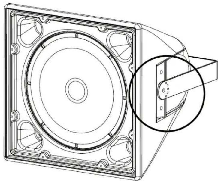
a) Horizontal U bracket installation: fix the loudspeaker to the U bracket by tightening the 2 bolts (M10) into the 2 loudspeaker central holes.
Before tightening the 2 bolts, adjust the loudspeaker tilt and then (when you are sure of the proper angle) fix that position through thread-forming screws into the U bracket little holes next to the central hole for bolts.
Note: do Not tilt the loudspeaker upwards!

natural_image
Technical line drawing of a mechanical component with concentric circular features and a magnified inset showing a cylindrical feature (no text or symbols)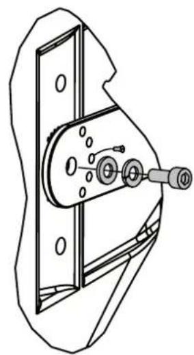
natural_image
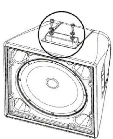
Technical line drawing of a mechanical component with no visible text or symbolsb) Vertical U bracket installation: put the 2 shims on the loudspeaker and fix them by tightening 2 pairs of bolts (M10), then fix the loudspeaker to the U bracket by tightening other 2 bolts into the 2 loudspeaker central holes.
Before tightening the last 2 bolts, adjust the loudspeaker horizontal aiming angle and then (when you are sure of the proper angle) fix that position through thread-forming screws into the U bracket little holes next to the central hole for bolts.
natural_image
Technical line drawing of a rectangular electronic device with internal components and a magnified inset showing a bracket (no text or symbols)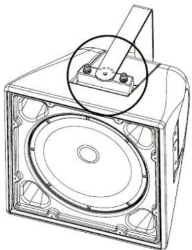
natural_image
Technical line drawing of a speaker or audio device with a circular component inserted, showing no text or symbols.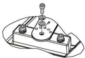
natural_image
Technical line drawing of a mechanical component with mounting holes and a central hub (no text or symbols)The optional RCF AC P15 A-BR kit includes the necessary accessories for a cluster made of 2 loudspeakers: i.e. P6215 with P8015-S subwoofer or P3115-T with P8015-S subwoofer.
Two AC P15 A-BR kits are necessary for a cluster having 3 or (maximum) 4 loudspeakers.
Warning: do noT make clusters With more Than 4 loudspeakers (each).
SETTING OF THE ANGLE BETWEEN 2 LOUDSPEAKERS
The angle between the 2 cluster loudspeakers depends on how the U brackets are matched. The possible values are: 0^ (no angle, the 2 loudspeakers are aimed to the same direction), 10^ , 20^ , 30^ , 40^ .
A dedicated acoustic project / study is to be carried out to find the proper angle.

SETTING OF THE ANGLE BETWEEN 2 LOUDSPEAKERS
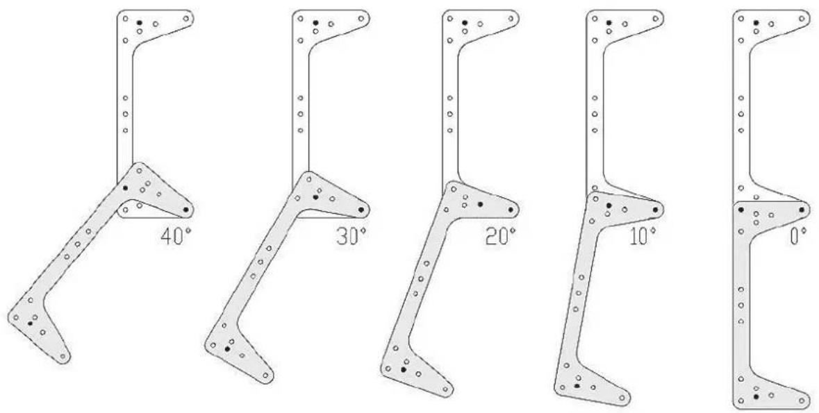
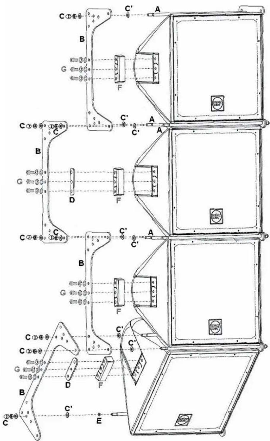
Note: black dots are the holes where to fix the 4 rods.

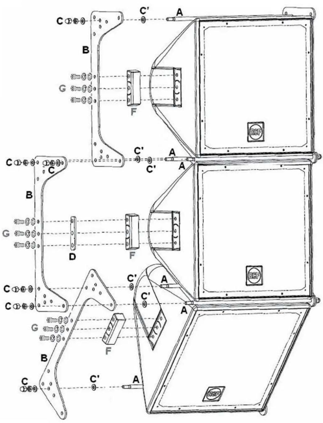
- 4 rods (A)
- 4 U brackets (B)
- nuts and washers (C)
- washers (C')
- 2 plates / spacers (D)
- 2 washers / spacers (E)
Note: the 4 shims (f) are provided with the 2 loudspeakers and each shall be fixed through 3 bots (g) with washers (m10, NoN included).
Put together and fix the 2 loudspeakers to the U brackets on both sides. The 2 spacers per side (the plate 'D' and the washer 'E') are needed for the second loudspeaker only.
natural_image
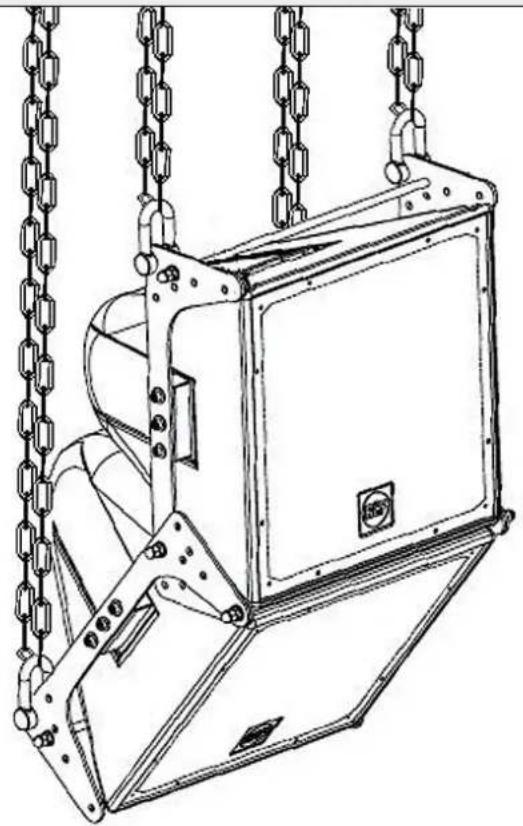
Technical line drawing of a mechanical device with chains and a central housing (no text or symbols)Use 4 M10 D-shackles (not included, 2 on the top and 2 on the bottom; put on the rear corner holes of the U brackets) for the suspended installation with chains (non included).
EXAMPLES OF 3 OR 4 LOUDSPEAKER CLUSTERS
2 identical kits are necessary for a cluster having 3 or 4 loudspeakers.
- 6 rods (A)
- 6 U brackets (B)
- nuts and washers (C)
- washers (C')
- 2 plates / spacers (D) for the second loudspeaker only.
- 8 rods (A)
- 8 U brackets (B)
- nuts and washers (C)
- washers (C')
- 4 plates / spacers (D) for the second and the fourth loudspeaker only.
- 2 washers / spacers (E) for the fourth loudspeaker only.
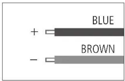
Warning: loudspeaker connections should be only made by qualified and personnel having the technical know-how or sufficient specific instructions (to ensure that connections are made correctly) in order to prevent any electrical danger. To prevent any risk of electric shock, do not connect loudspeakers when the amplifier is switched on. Before turning the system on, check all connections and make sure there are no accidental short circuits.
The entire sound system shall be designed and installed in compliance with the current local laws and regulations regarding electrical systems. If the P 8015-S subwoofer is installed outdoor (and IP 55 protection grade is required), all electrical connections shall be put into weatherproof boxes / wall niches.
P 8015-S subwoofer impedance is 8 Ω.
Connect the loudspeaker BLUE wire to the amplifier output '+'. Connect the loudspeaker BROWN wire to the amplifier output '-'
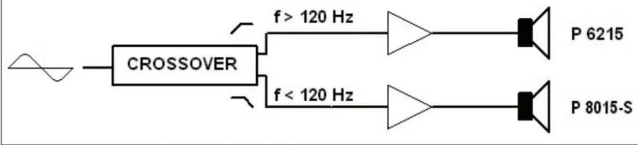
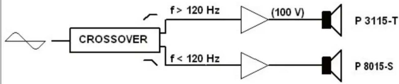
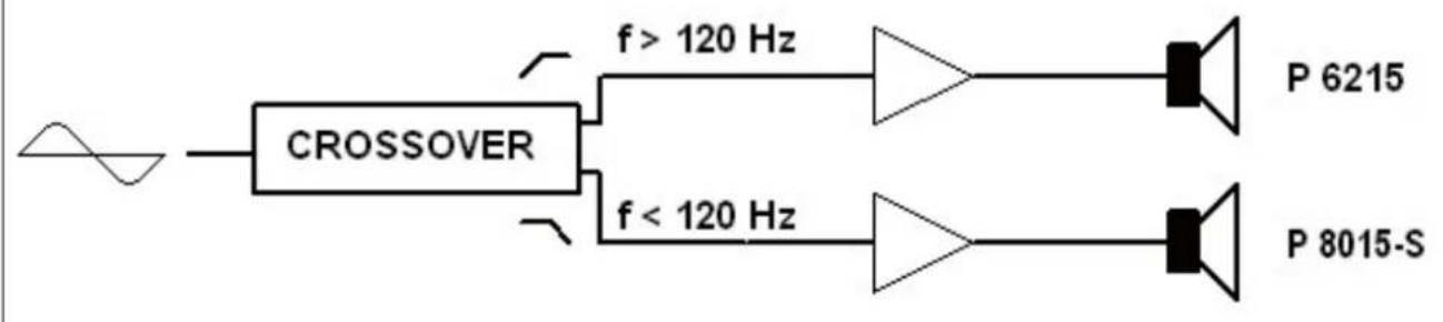
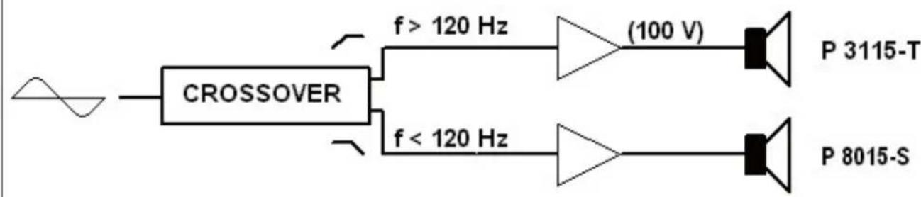
P 8015-S subwoofers are dedicated for very low frequencies only, so these are to be used with 'satellite' loudspeakers. Separate amplification and an external crossover are needed.

EXAMPLES OF BI-AMPLIFIED SYSTEMS
flowchart
graph LR
    A["Waveform"] --> B["CROSSOVER"]
    B --> C["f > 120 Hz"]
    B --> D["f < 120 Hz"]
    C --> E["P 6215"]
    D --> F["P 8015-S"]
flowchart
graph LR
    A["Waveform"] --> B["CROSSOVER"]
    B --> C["f > 120 Hz"] --> D["(100 V)"] --> E["P 3115-T"]
    B --> F["f < 120 Hz"] --> G["Diode"] --> H["P 8015-S"]
P8015-S subwoofer can be matched to either P6215 or P3115-T (note: these are the optimal solutions in order to make common clusters, but it is also possible to use other separate 'satellite' loudspeakers). The audio signal is split by an external crossover; suggested cutoff frequency is 120 Hz. All frequencies below 120 Hz are sent to amplifiers for P 8015-S subwoofers, all frequencies above 120 Hz are sent to amplifiers for 'satellite' loudspeakers (i.e. either P 6215 or P 3115-T).
NOTES ABOUT LOW IMPEDANCE CONNECTIONS
- The total loudspeaker impedance must not be lower than the amplifier output impedance. Note: a loudspeaker total impedance equal to the amplifier output one permits to get the maximum deliverable power (but an higher loudspeaker impedance entails less power).
- The total loudspeaker power shall be adequate for the maximum deliverable power of the amplifier.
- The loudspeaker line shall be short (for long distances, it may be necessary to use cables with large cross-section wires).
NOTES ABOUT LOW IMPEDANCE CONNECTIONS
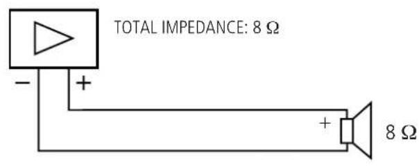
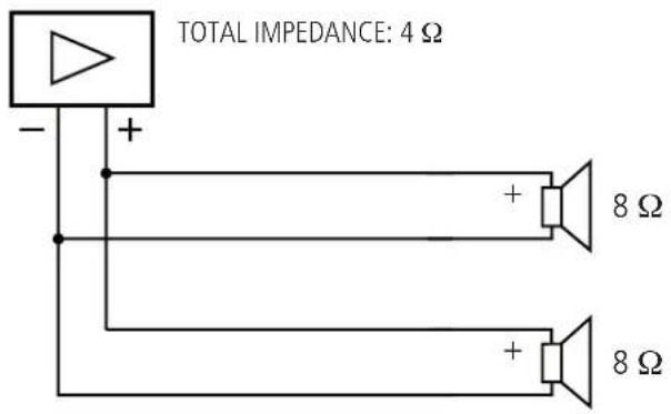
- Always use cables having wires with an adequate cross-section, considering the cable length and the total loudspeaker power.
- Loudspeaker lines must be kept separated from mains cables, microphone cables or others, in order to avoid inductive phenomena may cause hum or noises.
- Use loudspeaker cables with twisted wires to reduce hum caused by inductive effects due to coupling with electromagnetic fields.
- Do NOT connect the low impedance input directly to 100 V constant voltage lines.
Impedance
Max. input power (RMS)
Max. input power (peak)
Recommended amplifier power
Sensitivity (1 W, 1 m)
Max. sound pressure level (1 m)
Frequency response (-10 dB)
Suggested frequency for external crossover
Dimensions (w, h, d)
Net weight
Transducer
Enclosure
Colour
Rigging inserts
Accessories included
Grille
8 Ω
800 W
3200 W
1600 W
97 dB
132 dB (P: 3200 W)
50 Hz ÷ 200 Hz
120 Hz
463 mm, 463 mm, 433 mm
18.3 kg
15" woofer (4" coil)
trapezoidal, polyethylene rotomoulded grey
12×M10
a U-bracket, 2 M10 bolts, 2 spacers, 4
washers, 2 thread-forming screws, 4 plugs for the reflex ports
custom perforated aluminium with open-cell fibre water repellent woven fabric backing
AVVERTENZE PER LA SICUREZZA

IMPORTANTE
natural_image
Technical line drawing of a mechanical component with concentric circular features and a magnified inset showing a bracket detail (no text or symbols)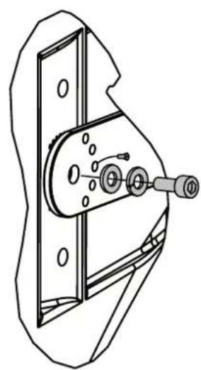
natural_image
Technical line drawing of a mechanical component with no visible text or symbolsnatural_image
Technical line drawing of a rectangular electronic device with internal components and a magnified inset showing a mechanical assembly (no text or symbols)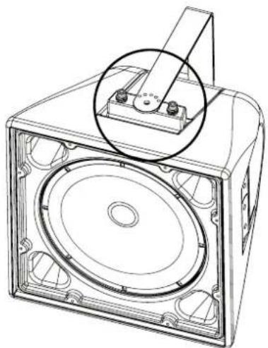
natural_image
Technical line drawing of a speaker or audio device with a circular component and mounting bracket (no text or symbols)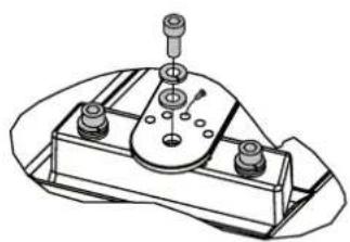
natural_image
Technical line drawing of a mechanical component with mounting holes and a central hub (no text or symbols)natural_image
Technical line drawing of a mechanical device with chains attached, no visible text or symbolsCLUSTER CON 4 DIFFUSORI
flowchart
graph LR
    A["Waveform"] --> B["CROSSOVER"]
    B --> C["f > 120 Hz"]
    B --> D["f < 120 Hz"]
    C --> E["P 6215"]
    D --> F["P 8015-S"]
flowchart
graph LR
    A["Waveform"] --> B["CROSSOVER"]
    B --> C["f > 120 Hz"] --> D["(100 V)"] --> E["P 3115-T"]
    B --> F["f < 120 Hz"] --> G["Diode"] --> H["P 8015-S"]
- OWNER MANUAL MANUALE D'USO
- P 8015-S
- INDEX INDICE
- ENGLISH
- ITALIANO
- SAFETY PRECAUTIONS
- IMPORTANT
- WARNING
- Hearing loss
- DESCRIPTION
- INSTALLATION NOTES
- SEALED OR BASS-REFLEX
- SETTING OF THE ANGLE BETWEEN 2 LOUDSPEAKERS
- EXAMPLES OF 3 OR 4 LOUDSPEAKER CLUSTERS
- NOTES ABOUT LOW IMPEDANCE CONNECTIONS
- Impedance
- Transducer
- AVVERTENZE PER LA SICUREZZA
- IMPORTANTE
- CLUSTER CON 4 DIFFUSORI
Brand : RCF
Model : P 8015S
Category : Subwoofer