
VDO Face 5 HC - Video Conferencing System MARTIN - Free user manual and instructions
Find the device manual for free VDO Face 5 HC MARTIN in PDF.


| Product Type | LED Video Display Panel (High Contrast) |
| Model | VDO Face 5 HC |
| Brand | Martin (HARMAN Professional) |
| Pixel Pitch | 5.208 mm (0.205 in) |
| Resolution per Panel | 96 x 108 pixels (10,368 pixels) |
| Brightness | 3000 nits (calibrated mode) |
| Dimensions (W x H x D) | 500 x 562.5 x 105 mm (19.7 x 22.2 x 4.2 in) |
| Weight | 10.5 kg (23.2 lbs) |
| Power Supply | Auto-sensing 100-240 V, 50/60 Hz |
| Power Consumption (Peak) | 260 W per panel (full white) |
| Power Consumption (Typical) | 87 W per panel |
| Cooling | Convection (silent) |
| Protection Rating | IP65, NEMA 4 (indoor/outdoor non-permanent) |
| LED Refresh Rate | 3400 Hz |
| Color Resolution | 16 bits per color (48 bits per pixel) |
| Viewing Angle (H x V) | 160° x 140° |
| Connections | Neutrik PowerCON TRUE1 (power in/thru), Neutrik EtherCON Cat 6 (data in/thru) |
| Max Panels per Power Chain | 10 panels at 100-120 V, 20 panels at 200-240 V |
| Max Panels per Data Chain | 50 panels (via P3 link) |
| Max Ambient Temperature | 45°C (113°F) |
| Installation Options | Flying (up to 14 panels high), stacked (up to 8 panels high), single panel clamp |
| Spare Parts (LED Blocks) | Left HC P/N 91616065, Right HC P/N 91616066 |
| Cleaning | Vacuum or damp cloth with mild detergent; avoid abrasives |
Frequently Asked Questions - VDO Face 5 HC MARTIN
User questions about VDO Face 5 HC MARTIN
0 question about this device. Answer the ones you know or ask your own.
Ask a new question about this device
Download the instructions for your Video Conferencing System in PDF format for free! Find your manual VDO Face 5 HC - MARTIN and take your electronic device back in hand. On this page are published all the documents necessary for the use of your device. VDO Face 5 HC by MARTIN.
USER MANUAL VDO Face 5 HC MARTIN
VDO Face 5™ Video Panel
User Manual
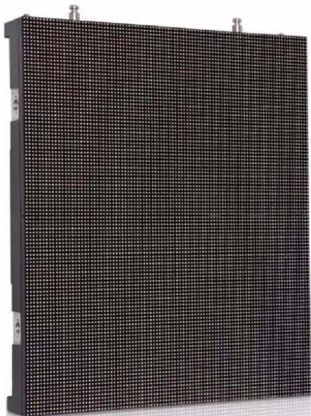
natural_image
Close-up of a black rectangular electronic panel with a grid pattern, mounted on a flat surface (no visible text or symbols)Dimensions

All dimensions are in millimeters
Information subject to change without notice. HARMAN Professional Denmark ApS disclaims liability for any injury, damage, direct or indirect loss, consequential or economic loss or any other loss occasioned by the use of, inability to use or reliance on the information contained in this document. ©2010-2018 HARMAN Professional Denmark ApS. All rights reserved. Martin® is a trademark of HARMAN Professional Denmark ApS registered in the United States and/or other countries. Features, specifications and appearance are subject to change without notice.
HARMAN Professional Denmark ApS - Olof Palmes Allé 18 - 8200 Aarhus N - Denmark www.martin.com
VDO Face 5 Single Header

VDO Face 5 Double Header

VDO Face 5 Curving Header

All dimensions are in millimeters
VDO Face 5 Panel Clamp
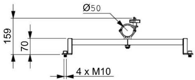
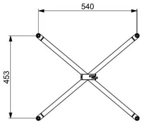
All dimensions are in millimeters
VDO Face Footer floor stand system

Panel mount ladder

All dimensions are in millimeters
Safety Information

WARNING!
Read the safety precautions in this section before installing, powering, operating or servicing VDO Face 5 ^TM products.
The following symbols are used to identify important safety information on the product and in this manual:

Warning!
Safety hazard. Risk of severe injury or death.

Warning!
Refer to manual before installing, powering or servicing.
Warning!
Hazardous voltage. Risk of lethal or severe electric shock.

Warning!
Hot surface. Do not touch.

Warning!
Fire hazard.

Warning!
Emission hazardous to eyesight.

This product is for professional use only. It is not for household use.
This product presents risks of severe injury or death due to fire hazards, electric shock and falls.

A revised version of this user manual will become available each time we can improve the quality of the information we provide in it. Please check that you have the latest revision of the user manual for this product before installing, operating or servicing the product. Martin® user manual revisions are identified at the bottom of page 2. You can download the latest user documentation from the product's Product Support / Tech Docs page on the Martin® website at www.martin.com.
The instructions and safety limits given in this user manual are provided to make sure that installers comply with the safety standards that apply to stage and studio environments. Follow these instructions carefully and do not exceed the limits given, or you may create an installation that is dangerous and does not meet required safety standards. Observe all locally applicable laws, regulations and codes regarding the safety of permanent and temporary structures, installations and electrical systems.
Read this manual before installing, powering, operating or servicing this product, follow the safety precautions listed below and observe all warnings given in this manual and printed on the product.
If you have questions about how to install or operate the VDO Face 5 ^™ system safely, please contact your Martin supplier or call the Martin 24-hour service hotline on +45 8740 0000, or in the USA on 1-888-tech-180.
PROTECTION FROM ELECTRIC SHOCK
- Connect the product to AC mains power within the range 100-240 V nominal at 50 or 60 Hz only.
- Disconnect the entire installation from power and ensure that power cannot be reconnected, even accidentally, before carrying out any installation or maintenance work.
- Disconnect the product from power when not in use.
• Always ground (earth) the product electrically. - Use only a source of power that complies with local building and electrical codes. Power distribution circuits must be fitted with an overcurrent fuse or circuit breaker with a maximum rated current of 20 A and ground-fault (earth-fault) protection of high breaking capacity ( ≥ 1500 A).
- Make power connections between VDO Face 5^TM panels using only the cables supplied by Martin for this purpose.
-
Protect power connections from water and rain.
-
Keep the attached rubber caps installed on any unused power and data connectors at all times. Reinstall caps over connectors as soon as a video wall is disassembled.
- Connect a VDO Face 5^TM installation to power using only 20 amp-rated industrial Type B power plugs and socket outlets that comply with IEC 60309 (or a comparable national standard) and provide an electrical connection to ground (protective earth).
- When using AC mains power at 100-120 V, connect a maximum of ten (10) VDO Face 5^TM panels in total to AC power in one chain using the power IN and OUT connectors in the back of the panels. When using AC mains power at 200-240 V, connect a maximum of twenty (20) VDO Face 5^TM panels in total to AC power in one chain using the power IN and OUT connectors in the back of the panels.
- Before using the product, check that all power distribution equipment and cables are in perfect condition and rated for the current requirements of all connected devices.
- Do not use the product if the panel, a power cable, a power connector or a seal around a multi-connector in the back of a panel is in any way damaged, defective or showing signs of overheating.
- Do not attempt to open the product.
- Refer any service operation not described in this manual to an authorized Martin® service agent.

PROTECTION FROM FIRE AND BURNS
- Provide a minimum clearance of 10 cm (4 in.) around the front and back of the panel.
- Ensure good ventilation around the panel, controller, power supply and all other devices in the installation.
- Do not stick filters, masks or other materials directly onto LED modules.
- Do not modify the product in any way not described in this manual.
- Install only genuine Martin parts and parts described in this manual in or on the product.
- Do not operate the product if the ambient temperature ( T_a ) exceeds 45° C (113° F).
- The cover on the back of the product can become hot, up to 72^ C (162° F) if running constantly at full intensity, full white. Avoid accidental skin contact.

PROTECTION FROM INJURY
- Do not install VDO Face 5™ panels using any other method or any other equipment than those described in this manual.
- Make sure that any structure used for support can hold at least ten (10) times the weight of all the items it supports.
- Check that all panels, rigging hardware and other elements in the installation are securely fastened and cannot fall, causing injury or damage.
- Block access below and around the work area and work from a stable platform whenever installing, servicing or moving items in the installation.
- Do not look at lit LEDs from a distance of less than 1 m (3 ft. 4 in.) without suitable protective eyewear.
- Be prepared for panels to light up suddenly if they receive a video signal.
- Do not view lit LEDs with optical instruments that may concentrate the light output.

PROTECTION FROM INJURY CAUSED BY WIND PRESSURE
Wind can create a risk of serious or lethal injury and damage due to falling panels. In any location where an array of VDO Face 5 ^™ panels may be exposed to wind pressure or other air currents, take the following precautions:
- Support panels using a structure that is capable of holding the panels securely without any safety risk when panels are exposed to wind pressure.
- Secure panels against any swinging, snaking or other lateral movement that might occur when panels are exposed to wind pressure. Fasten panels to anchoring points as directed in this user manual.
- Ensure that professional technicians constantly monitor weather forecasts and local wind speed at the installation site. Technicians must remove all panels from the installation immediately in the following situations:
- In flying installations where VDO Face 5 ^™ panels are suspended from VDO Face Headers, remove all panels from the installation immediately if constant or gusting wind speed that exceeds Force 8 Beaufort, 20 m/s or 45 mph is forecast for, or present at, the installation location.
- In standing installations where VDO Face 5 ^™ panels are supported on VDO Face Footer floor stands, remove all panels from the installation immediately if constant or gusting wind speed that exceeds Force 2 Beaufort, 3 m/s or 7 mph is forecast for, or present at, the installation location.


SAFETY PRECAUTIONS FOR FLYING INSTALLATIONS
Respect the following precautions when installing an array of panels hanging from the Face Header suspension system:
- Respect the maximum limits given in this user manual for the number of panels that you can suspend vertically. The maximum limit varies depending on installation type. Make sure that you respect the limit that applies in the installation concerned.
- Make sure that each separate item of rigging hardware (chain, cable, shackle, etc.) can hold at least ten (10) times the total weight of the header, panels, hardware, cables etc. that are suspended under that item. For example, if a header and all the panels, hardware, cables etc. hanging from it weigh 100 kg in total, each item that is used to suspend that 100 kg load must be capable of supporting 1000 kg. This requirement applies to single and double headers. The requirement also applies regardless of whether a header is supported by one, two or three chains or cables: if the 100 kg load in the example above is suspended from three chains, then each chain must be capable of supporting 1000 kg.
- Make sure that each eyebolt that is used to suspend or secure a column of panels is fastened to the supporting structure with its own cable or chain. Do not loop one cable or one chain through more than one eyebolt.
- Start by installing headers. Then install panels at the top and work downwards.
- Do not suspend VDO Face 5^TM panels at any other angle than hanging vertically downward.
- Make sure that there is no slack in any item of rigging hardware: all cables, chains, etc. used for suspension must be equally tight.
- Disassemble a suspended installation by removing panels at the bottom and working upwards. Do not remove headers until all panels have been removed.


SAFETY PRECAUTIONS FOR STACKED INSTALLATIONS
Respect the following precautions when creating a free-standing array of panels using the Face Footer floor stand system:
- Respect the limits given in the 'Physical installation' chapter of this user manual for the number of VDO Face 5™ panels that you may install in a vertical column and the minimum weight of ballast that you must fasten to each stabilizer leg. These limits vary depending on installation type. Make sure that you respect the limits that apply in the installation concerned.
- Start by installing base units and adjust level if necessary, then install stabilizer legs, ballast and panel support ladders. Finally, install panels.
- Do not stack panels using the VDO Face Footer system at any other angle than standing vertically.
- Do not install items weighing more than 90 kg (199 lbs.) on a Face Footer floor stand base unit. This means that you must not install more than eight (8) Martin® VDO Face 5^TM video panels and the fastening hardware described in this user manual in a vertical column on one Face Footer floor stand.
- Fasten at least one stabilizer leg to the outside end of each base unit at the edges of a Face Footer installation.
- Fasten at least one stabilizer leg to every base unit in the installation.
- When adjusting the feet of Face Footer floor stand elements to make sure that they are horizontally level, check that no more than 20 mm (0.8 in.) of threaded shaft is visible between the adjustment nut on each foot and the locknut on the foot's threaded shaft. Readjust the feet on all the elements or, if necessary, add supporting plates under the feet that are strong enough and stable enough to safely support the load that will be placed on them.
- Do not install panels on the Face Footer system before you have fastened all required ballast to the stabilizer legs.
- Make sure that any ballast that is fastened to stabilizer legs cannot be removed while panels are installed on the Face Footer system.
- Install VDO Face video panels on the Face Footer system only if the installation is located on a stable surface that is capable of safely supporting the total load placed upon it and if the installation will not be subject to shock, vibration or any other movement.
- Do not create an array using the Face Footer system that consists of only a single column of VDO Face 5 ^TM panels. Install a minimum of two columns of VDO Face 5 ^TM panels with base units and panels securely fastened to each other side-by-side as described in this user manual.
- Do not climb on or rest ladders against an installation that uses the Face Footer system.
- Do not move or transport the Face Footer system with panels installed. Remove panels before moving or transporting base units and stabilizer legs.
- When you tear down an array of video panels, do not remove any ballast from Face Footer stabilizer legs until all panels have been removed from the installation.
- Disassemble a stacked installation by removing panels at the top and working downwards.
Contents
Safety Information....6
Introduction 10
Panels and flightcases....10
Avoiding damage to panels 11
Using for the first time 11
Overview 12
Physical installation 13
Installing single panels on a truss or structure. 14
Stacking panels on floor stands. 15
Flying panels in a flat array 23
Flying panels in a curved array 36
Dismantling a flying installation 39
AC power 40
Power connections 40
Inrush current and earth leakage....41
Fuses....42
P3 communication link 43
Planning the P3 link....43
Connecting the P3 link....44
Operation 45
Monitoring status and testing....45
Service and maintenance....46
Storage 46
Cleaning. 46
Installing new software 46
Replacing an LED block 46
Troubleshooting 48
Specifications 49
Introduction
Thank you for selecting the Martin® VDO Face 5™ modular LED-based video display panels from Martin®. Panels are available in HB (High Brightness) models that are optimized for intensity of output, and HC (High Contrast) models with darker front surfaces that provide deep contrast. The two models are identical apart from their different quick-release LED blocks.
The VDO Face 5 ^TM range features:
- 5.208 mm (0.205 inch) pixel pitch and 96 x 108 pixels per panel image resolution
- 5000 nits performance (HB models)
• 3000 nits performance (HC models) - Rich RGB with color resolution of 16 bits per color
- Weatherproofing to IP65: suitable for indoor and non-permanent outdoor installation
- Flying and stacked installation system options
- Integrated quick-locking vertical and side-to-side panel attachment system
- Quick-release hot-swappable LED blocks (four per panel)
- Silent convection cooling
- Dual power supply design for maximized protection from data throughput interruption
• Auto-sensing 100 - 240 V, 50/60 Hz switch mode power supply
For information about installing and using a P3 System Controller, see the user documentation supplied with the Controller.
All Martin® video display and P3 controller user documentation is available for download from the Product Support / Tech Docs pages at www.martin.com
Comments or suggestions regarding this document may be e-mailed to service@martin.dk or posted to: Technical Documentation, Martin Professional A/S, Olof Palmes Allé 18, DK-8200 Aarhus N, Denmark.

Warning! Read 'Safety Information' starting on page 6 before installing, powering, operating or servicing VDO Face 5^TM products.
A VDO Face 5 ^™ panel is an ITE Class A product. In a domestic environment this product may cause radio interference, in which case the user may be required to take appropriate measures.
Panels and flightcases
VDO Face 5 ^TM panels are ordered as single panels that are supplied in cardboard boxes.
To transport panels, pack them in the six-unit VDO Face flightcases available from Martin® (see
"Accessories" on page 27) to ensure that they can withstand the shocks that normally occur while panels are in transit.
See Figure 1. Flightcases have space for storing cables and installation hardware.
See also the information on modular flightcases for the VDO Face Footer floor stand system on page 22.

natural_image
3D rendering of an VDO Face™ flightcase with open lid and internal compartments (no text or symbols on the device itself)Avoiding damage to panels
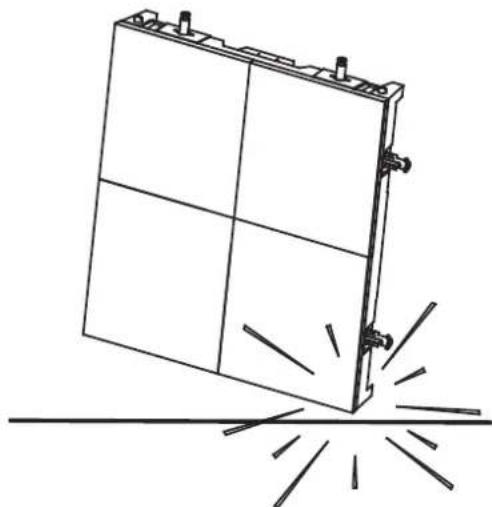
Important! VDO Face panels and LED blocks have LEDs at their edges. This makes LEDs liable to damage if panels and LED blocks are not handled with care. See Figure 2. Protect the edges of panels and LED blocks from shocks at all times.
Keep panels in Martin® flightcases to protect them during transport and storage.
Damage caused to panels that are exposed to shocks or incorrectly packed is not covered by the product warranty.
natural_image
Line drawing of a rectangular panel with four sides and a central spike, emitting radiating lines (no text or symbols)Figure 2: Protect edges from shocks
Using for the first time
Before applying power to the panel:
- Carefully review "Safety Information" on page 6.
- Check that the local AC power voltage is within the ranges listed on the product's serial number label and in "AC power" on page 40.
- With reference to this user manual, make sure that you have enough VDO Face 5™ Headers (including any additional eyebolts required) to suspend panels vertically, all required rigging hardware, and enough cables for power and data input and daisy-chaining.
Overview
Header

Single Header illustrated
Panel

A - Vertical fastener plate (in header)
B - Primary attachment eyebolt
C - Mounting points for eyebolt brackets or header side attachment brackets
D - Side-to-side fastener bar
E - Side-to-side fastener lever
F - Side-to-side locking lever
G - Data OUT (THRU) connector
H - Power OUT (THRU) connector
I - Vertical fastener post
J - Vertical fastener post locking lever
K - Side-to-side fastener receptacle
L - Data IN connector
M - Power IN connector
N - Vertical fastener locking plate (in panel)
O - Single header
P - Header side attachment bracket
Figure 3: Product overview
Physical installation

Warning! Read 'Safety Information' starting on page 6 before installing VDO Face 5^TM products.
The safety and suitability of lifting equipment, installation location, anchoring method, mounting hardware, suspension structures and electrical installation is the responsibility of the installer. Observe all local safety regulations and legal requirements when installing and connecting VDO Face 5™ panels. Installation must be carried out by qualified professionals only. Contact your Martin® supplier for assistance if you have any questions about how to install this product safely.
If VDO Face 5 ^™ video panels are installed as directed in this user manual, they meet the safety requirements of stage and studio environments when they are either:
- individually fastened to Martin® VDO Face Panel Clamps and mounted on a structure such as a rigging truss or bar,
- suspended from Martin® VDO Face Headers in vertical columns a maximum of fourteen (14) panels high, or
- stacked on Martin® VDO Face Footer floor stands in vertical columns a maximum of eight (8) panels high.
The figures given above are maximum figures. Lower limits than these maximums may apply to the number of panels that may be suspended or stacked vertically, depending on how the panels are installed: see the relevant sections of this chapter.
An unlimited horizontal number of correctly supported columns of panels may be attached side-by-side to form a video display surface.
It is possible to connect various Martin® LED video products to a Martin® P3 System Controller in an installation. The System Controller will recognize the different products.
Before installing
Before creating an installation with VDO Face 5 ^TM panels:
- Read "Safety Information" on page 6 and take special note of the precautions that are relevant for installing products.
- Check that supporting structures will not flex under the weight of the panels. Suspending panels from a structure that is not correctly aligned or not rigid enough will place a strain on panels and attachment hardware. Damage caused to headers or panels by mechanical stress is not covered by the product warranty.
- Check that circuits in the installation are isolated from power and that power cannot be applied accidentally.
- Block access under and around the work area.
Types of installation
The rest of this chapter covers four types of installation:
- For guidance on individually mounting VDO Face 5 ^™ panels, see “Installing single panels on a truss or structure” on page 14.
- For guidance on creating a stacked array of multiple VDO Face 5 ^™ panels, see “Stacking panels on floor stands” on page 15.
- For guidance on creating a flown array in which multiple VDO Face 5 ^™ panels form a flat video display surface, see “Flying panels in a flat array” on page 23.
- For guidance on creating a curved flown array, in which multiple VDO Face 5 ^TM panels form a video display surface with a convex or concave horizontal curve, see “Flying panels in a curved array” on page 36.
Installing single panels on a truss or structure
The VDO Face Panel Clamps available from Martin® (see "Accessories" on page 51) give enormous flexibility in arranging panels in creative video displays. Each Panel Clamp lets you fasten one single VDO Face 5^TM panel to a rigging truss or similar structure. If you want to create an array consisting of two more panels, see later in this chapter.
See Figure 4. The VDO Face Panel Clamp consists of a large bracket A with four arms in an 'X' shape. A half-coupler rigging clamp C is located at the center of the 'X'.
To install a VDO Face 5™ panel on a VDO Face Panel Clamp:

natural_image
Close-up of a mechanical device with a labeled component (B) and no visible text or symbols on the main subject.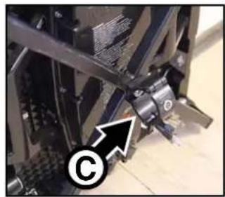
natural_image
Close-up of a mechanical component with a circular mark and arrow, no visible text or symbols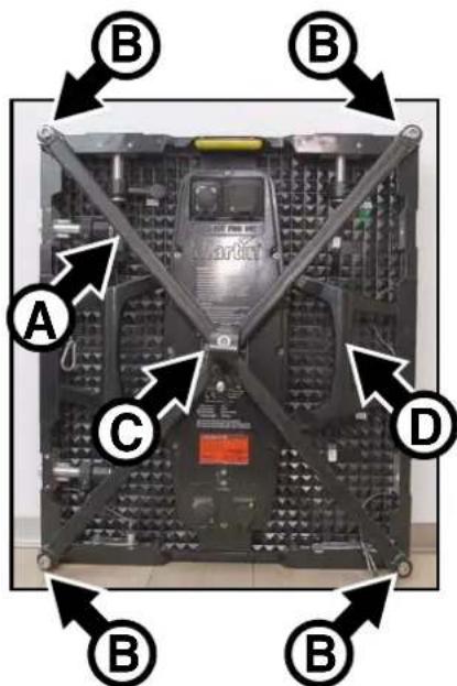
Figure 4: VDO Face Panel Clamp
-
Check that the structure that you will use to support the panel is capable of supporting ten times the weight of all the items that will be installed on it.
-
Restrict access below the work area and work from a stable platform.
-
See Figure 4. Bolt a Panel Clamp bracket A to the back of the VDO Face 5^TM panel using the four Allen (hex) bolts B supplied with the Panel Clamp.
-
Loosen the handscrew and open the half-coupler clamp C, then fasten the clamp around a 50 mm (2 inch) diameter chord on a rigging truss or similar bar. Use hand force only to tighten the handscrew: do not apply force with a tool.
-
As soon as you have fastened the clamp, loop an approved safety cable around the chassis of the VDO Face 5™ panel (at D for example) and around the supporting structure so that the safety cable will catch the panel if the half-coupler clamp fails. Take up as much slack as possible by looping the safety cable more than once around the supporting structure or panel chassis to reduce the size of the fall if the half-coupler clamp fails.
-
Do not use the panel you have just installed to support the weight of any other panel. Each panel must have its own VDO Face Panel Clamp.
Stacking panels on floor stands

Warning! See "Safety Information" on page 6 for important safety information on using the VDO Face Footer floor stand system.
Safety limits apply to the maximum number of VDO Face 5™ video panels that you can install vertically using the Footer System. Respect the limits and instructions given in the following section of this user manual, paying particular attention to the weight and position of ballast, or you may create a stack of panels that is unstable and may fall, causing lethal injury or damage.
The VDO Face Footer System is a range of optional floor stand accessories available from Martin® that let you install VDO Face video panels in a stacked array.
See Figure 5. The system consists of base units A, stabilizing legs B, vertical panel mount ladders C and all required fastener hardware.

Safety limits with single row of stabilizer legs
When stacking VDO Face 5 ^™ video panels in vertical columns on VDO Face Footer floor stands with one single row of stabilizer legs installed on the back of base units, see Figure 6. Fasten ballast
Figure 5: Face Footers floor stand system
such as sand bags to the rear end of each stabilizer leg, i.e. as close as possible to the back of the installation. The ballast must have at least the weight indicated in Figure 6 for the number of panels in the column. Do not stack more than eight (8) VDO Face 5™ panels in a vertical column.
Maximum 8 panels vertically with 90 kg ballast fastened to end of leg

| Number of panels installed vertically | Ballast required at rear end of each leg |
| 1-3 0 | |
| 4 15 kg (33 lbs.) | |
| 5 30 kg (66 lbs.) | |
| 6 45 kg (99 lbs.) | |
| 7 60 kg (132 lbs.) | |
| 8 90 kg (198 lbs.) |
Figure 6: Safety limit and ballast required with one row of stabilizer legs
Safety limits with two rows of stabilizer legs
When installing VDO Face 5™ video panels in vertical columns on VDO Face Footer floor stands with two rows of stabilizer legs installed on the back of base units, see Figure 7. Fasten ballast such as sand bags to the rear end of each rear stabilizer leg, i.e. as close as possible to the back of the installation. The ballast must have at least the weight indicated in Figure 7 for the number of panels in the column. Do not stack more than eight (8) VDO Face 5™ panels in a vertical column.
Maximum 8 panels vertically with 15 kg ballast fastened to rear end of rear leg

| Number of panels installed vertically | Ballast required at rear end of each rear leg |
| 1-3 0 | |
| 4 | 0 |
| 5 | 0 |
| 6 | 0 |
| 7 | 0 |
| 8 15 kg (33 lbs.) | |
Figure 7: Safety limit and ballast required with two rows of stabilizer legs
Creating a stacked array
Installing VDO Face Footer system components
To create a free-standing array of VDO Face 5 panels to form a flat video display surface:
-
Unpack the components from their flightcase. It will simplify repacking if you note how they are packed by taking photos with a smartphone, for example.
-
Lay out bases and stabilizer legs as shown in Figure 8. You must fasten legs B into base units A at each edge of the array. You must also fasten a stabilizer leg C into one of the base units A each time you join two base units side by side (see D). It does not matter which of the two base units you fasten the leg C into.

Figure 8: Face Footers components
- See Figure 9. To fasten a stabilizer leg into a base unit, pull and twist the leg lock into the open position, insert the leg into the base unit, and then twist the lock into the locked position so that the leg is locked into the base unit.
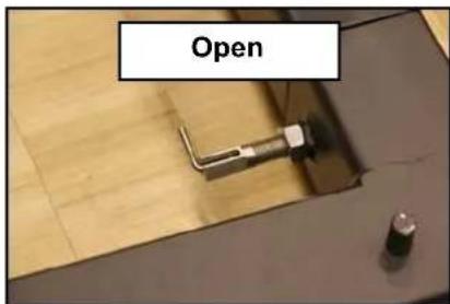
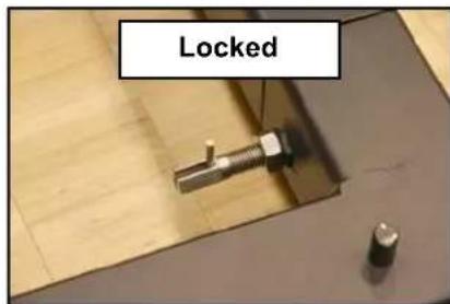
Figure 9: Locking legs into base units
- See Figure 10. Push the supplied pins through the holes at the edges of base units to link base units together in a straight line.
If you stabilize base units with one row of stabilizer legs (as shown in Figure 8), you can install an array of video panels up to the heights listed in Figure 6 on page 15 if you fasten the amount of ballast specified in Figure 6 to the rear end of each stabilizer leg.
If you stabilize base units with two rows of stabilizer legs, you can install an array of video panels up to the heights listed in Figure 7 on page 16 if you fasten the amount of ballast specified in Figure 7 to the rear end of each stabilizer leg in the back row.

natural_image
Close-up of a hand operating a mechanical clamp or fixture with two circular base components, no visible text or symbols.Figure 10: Linking base units
- Base units and stabilizer legs must be horizontal when installed. Bases and legs have adjustable feet to compensate for uneven floors. When all base units and stabilizer legs are fastened together in their final position (and before you install panels), use a spirit level to check that components are horizontal from side to side and from front to back. See Figure 11. If necessary, loosen locknuts E and raise or lower feet by turning adjustment nuts D until components are horizontal. Then retighten locknuts E. Do not screw feet too far out of the base units: no more than of 20 mm (0.8 in.) of thread must be visible between the adjustment nut D and locknut E.
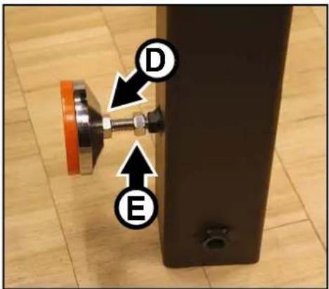
Figure 11: Foot adjustment
- See Figure 12. Push the supplied truss eggs into the ends of the panel support ladders and secure them with pins and securing clips F. Then push the ladders into the supports in the base units so that the ladders stand vertically. Secure the ladders with pins passed through the truss eggs and securing clips G so that the ladders are fastened securely into the base units.


natural_image
Close-up of two black cylindrical objects with attached metal brackets and a directional arrow labeled 'G' pointing upward (no text or symbols on objects)Figure 12: Installing ladders
-
The Face Footer system will now look like the installation shown in Figure 13 (this is the minimum size installation that can be created using the Face Footer system: as a minimum the array must be two panels wide and two panels tall).
-
Install additional ladders so that there will be a ladder at both sides of every panel that you add above the first two panels. Install additional ladders using two truss eggs each time you add a ladder using the method shown in Figure 12. Fasten each truss egg with two pins, one passed through each ladder, and secure all pins with spring clips.
-
You must not move a Face Footer system with video panels installed, so adjust the position of the system until it is in its final position now and make a final check that base units are perfectly level before proceeding to add panels.

natural_image
Three vertical metal supports mounted on a wooden floor, arranged in a V-shape pattern (no text or symbols visible)Figure 13: Minimum stacked installation
Installing VDO Face 5 panels on the Face Footer system
Panel brackets
See Figure 14. Brackets for fastening panels to ladders are included in the Face Footer system. Viewed from the back of the panel array:
- bracket A fastens to two panels on the left-hand edge of the array,
• bracket B fastens to four panels in the middle of the array, and - bracket C fastens to two panels on the right-hand edge of the array.

natural_image
Three black metal clamp holders on a wooden surface, labeled A, B, C, and O (no text or symbols on the devices themselves)Figure 14: Face Footer panel brackets
The brackets are telescopic to allow for minor variations in the positions of panels. Brackets
clamp onto Face Footer panel support ladders with half-coupler clamps and bolt to panels with the supplied Allen (hex) head bolts.
Fastening panels into place
To install VDO Face 5 panels on the Face Footer components:
-
Check that the Face Footer components are correctly installed. Pay particular attention to "Safety limits with single row of stabilizer legs" on page 15. Check that the required weight of ballast for the number of panels that will be stacked vertically and for the number of stabilizer legs is fastened to the rear of the stabilizer legs and cannot be removed.
-
See Figure 15. Place the first panel over the upright pins (arrowed) in the top of the first base unit at the right-hand (as viewed from the back) edge of the array.

natural_image
Industrial machine component with black components and directional arrows indicating assembly or inspection (no readable text or symbols)Figure 15: Installing the first panel
- See Figure 16. Fasten a right-hand edge clamp to the ladder and first fixture as shown. Tighten the clamp-to-panel bolt A, then tighten the telescopic extension handwheel B and finally tighten the butterfly nut C on the ladder half-coupler.

Figure 16: Fastening first panel at right-hand edge of array
- See Figure 17. Lower the second panel onto the first panel and use the vertical locking posts and locking plates to fasten the two panels together with reference to "Instructions for suspending panels" on page 32. Check that the second panel is locked into place.

natural_image
Close-up of a mechanical device interior with labeled component 'A' and no visible text or symbols beyond the label.Figure 17: Fastening panels at right-hand edge of array
- See Figure 18. Pass the supplied Allen (hex) head bolts A through a central array panel bracket B. If you are creating a curved array, pass the bolts through a 5^ or 10^ curving alignment plate. Tighten the bolts into the holes in the inner edges of the video panels as shown. Then tighten the telescopic extension handwheel C and finally tighten the butterfly nut D on the ladder half-coupler. Check that the panels are locked into place.

Figure 18: Fastening panels inside the array
Continue adding panels to the array using the above instructions as a guide.
Use the correct panel brackets for the edges and middle of the array as described in 'Panel brackets' on page 19 and shown in Figure 14.
Do not lean ladders against or climb on the array of panels: work from a stable platform.
Each time you add a panel, fasten it to the existing panels above, below and on both sides as described above and as described in "Fastening panels side by side" on page 34. Then install panel clamps as described above.
Taking down a stacked array
When you tear down a free-standing array of video panels that are installed using the Face Footer system, you basically need to follow the procedure outlined above in reverse. Pay attention to the following:
- Block access under and around the installation. Do not climb on the installation: work from a stable platform.
- Do not remove any ballast from stabilizer legs until all panels and ladders have been removed from the installation.
- Do not remove stabilizer legs until all panels and ladders have been removed from the installation.
VDO Face Footer system flightcases
See Figure 19.
Flightcase elements with storage space for all items in the VDO Face Footer system including clamps and fasteners are available as modular accessories from Martin®. Elements fasten together for easy transport. See "Accessories" on page 51.

natural_image
Three stacked aluminum-framed electrical equipment cases on a wooden surface, no visible text or symbols
flowchart
graph TD
    A["Lid"] --> B["Ladders"]
    B --> C["Stabilizer legs"]
    C --> D["Base units"]
    D --> E["Example setup"]
Figure 19: Face Footers flightcase elements
Flying panels in a flat array
To suspend an array of VDO Face 5 ^™ video panels vertically to form a flat display surface, see below. To suspend array of VDO Face 5 ^™ video panels vertically to form a curved display surface, see “Flying panels in a curved array” on page 36.
To suspend a vertical column of VDO Face 5 ^™ panels, you must use a VDO Face system header. See below (Single Header illustrated):

A - Suspension eyebolt (primary attachment point)
B - Panel fastener plate
C - Panel fastener plate locking button
D - Mounting points for extra suspension eyebolts or header connection brackets.
Figure 20: VDO Face Single Header
VDO Face system headers are available in two versions:
- Single Headers have one suspension eyebolt A and holes D at each end of the header for mounting either side connection brackets or brackets for two further eyebolts. You can support one column of panels from one Single Header.
- Double Headers have three suspension eyebolts A and holes D at each end of the header for mounting side connection brackets. You can suspend two columns of panels from one Double Header.
Side connection brackets are supplied with headers (see next section).
Header side connection brackets

Warning! VDO Face Header side connection brackets are for alignment purposes only. Only fasten panels to a header if the header is suspended using its eyebolt as described in this user manual.
Before you install columns of VDO Face™ panels side-by-side, install headers and fasten them together using the header side connection brackets that are supplied with headers.

Figure 21: VDO Face Side Connection Brackets
To install a header side connection bracket:
-
See Figure 21. Each time you install two headers D beside each other, place a side connection bracket E over the ends of the headers and pass the four locking pins F supplied with the brackets through both the bracket and the headers.
-
Secure all four locking pins F with spring clips G.
Corner connection plates
VDO Face™ corner connection plates have both a load-bearing and a stabilizing function. You must fasten the corners of VDO Face™ panels together by installing corner connection plates on the rear face of VDO Face 5 panels in the following three situations:
1. Single columns
In any column of panels that is not joined to other panels at both sides and that is more than five (5) panels high, corner connection plates must be installed at all times on all four corners of every panel that is above the five (5) lowest panels in the column. See also Figure 23 on page 27.
2. Multiple columns
In an installation consisting of multiple columns hanging side by side that are fastened to each other using their integral side-to-side fasteners, in any column that is more than ten (10) panels high, corner connection plates must be installed at all times on all four corners of every panel that is above the ten (10) lowest panels. See also Figure 24 on page 29 and Figure 25 on page 31.
3. Columns that need to be stabilized
Where extra stabilization is required because of movement or vibration of the supporting structure or because of wind pressure, corner connection plates must be installed on all four corners of every panel in the installation.
To install connection plates:
- Read the guidelines above and plan the use of connection plates in your installation so that you know where you will need to install them. See Figure 22. You will need one connection plate B for each corner where two ore more panels meet and one M10x15 bolt with washer C per corner. Bolts must be steel, grade 8.8 minimum. Connection plates and suitable Allen bolts are available from your Martin® supplier.
- As soon as you have fastened a panel into the installation using the panels' integral fastening mechanisms, fasten connection plates B to the panels A using bolts with washers as shown in Figure 22. Fasten all adjacent corners together. Install connection plates continuously while you work so that you never exceed the limits (given under '1. Single columns' and '2. Multiple columns' above) for the number of panels that can hang freely without connection plates. Do not overtighten bolts.
- When tearing down an installation, remove panels starting from the bottom and do not remove connection plates until you are ready to remove the panels that the plates are fastened to.

A - VDO Face 5 panel
B - Connection plate
C - Connection plate fasteners (one M10 x 15 Allen head bolt per panel)
Figure 22: VDO Face™ corner connection plate
Anchoring the bottom of columns
Warning! Anchor the bottom of columns of panels to make it impossible for the columns to swing or snake if a primary attachment fails or if panels are exposed to air pressure.
Tighten anchoring straps at the bottom of columns gently by hand, and only enough to remove any slack. Do not tighten straps hard, or you may add to the downward force acting on columns and suspension hardware, creating a danger of failure.
To anchor the bottom of a column, fasten an M10 eyebolt or VDO Face 5 ^™ corner connection plate to the hole in the bottom corner of the panel at the bottom of the column, then loop a strap such as nylon webbing through the eyebolt or connection plate and around an anchoring point. Make sure that there is no slack in the strap, but tighten the strap gently by hand only.
- Anchor both sides of each single column of panels.
- Anchor both sides of each multiple array of columns.

Possible configurations
If suspension points are provided as directed in this user manual, vertical columns of VDO Face 5 ^™ panels can be suspended side-by-side to form a display surface of unlimited width, but in any location that can be regarded as stage/studio environment no column may be no more than fourteen (14) panels high.
The following sections and diagrams explain the different installation options available.
Single-column arrays
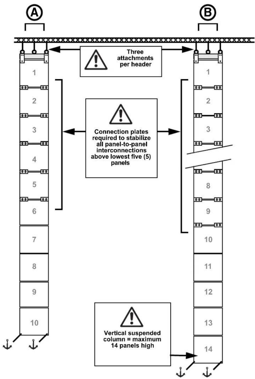
See A and B in Figure 23. You may suspend a single column of panels maximum fourteen (14) panels high from a single header. The column can hang alone without panels being fastened at the sides to other panels. In this type of installation:
- No column may be more than 14 panels high.
- You must install connection plates on all four corners of every panel above the lowest 5 panels in a column.
- You can install columns up to 5 panels high in an array without corner connection plates.
- The header must be suspended from three cables or chains. This means that you must install on the header two of the additional eyebolt brackets available from Martin® as accessories for the VDO Face 5™ and you must install suitable eyebolts on the brackets.
To create an array consisting of a single column of VDO Face 5 ^TM panels suspended from a single header:
- With reference to Figure 23, obtain enough corner connection plates available from Martin® to stabilize the column You will need two connection plates for each panel above the lowest five panels. The lowest five panels can hang from their integral fastening posts without connection plates.
- Install two additional eyebolt brackets on the single header using the mounting holes (see D in Figure 20 on page 23) at each end of the header.
- Suspend the header by fastening all three eyebolts to a safe structure using three separate cables or chains. Each individual cable or chain must be approved to support ten times the total weight of the column. Each eyebolt must have its own cable: do not loop one cable through more than one eyebolt. Make sure that there is no slack in cables: all cables must be equally tight.
- Install panels one by one under the Single Header as described in "Instructions for suspending panels" on page 32. Each time you add a panel, fasten it using both its vertical fastener posts, then immediately install corner connection plates to fasten the panel securely to the panel above it. Add corner connection plates until you reach the lowest five panels, which do not need the plates.
- Attach the column to anchoring points at its lower corners to make it impossible for the bottom of the column to move. Do not apply downward force to the column when attaching it.
flowchart
graph TD
    A["1"] --> B["2"]
    B --> C["3"]
    C --> D["4"]
    D --> E["5"]
    E --> F["6"]
    F --> G["7"]
    G --> H["8"]
    H --> I["9"]
    I --> J["10"]
    J --> K["11"]
    K --> L["12"]
    L --> M["13"]
    M --> N["14"]
    N --> O["Vertical suspended column = maximum 14 panels high"]
    P["Three attachments per header"] --> Q["1"]
    P --> R["2"]
    P --> S["3"]
    P --> T["8"]
    P --> U["9"]
    P --> V["10"]
    P --> W["11"]
    P --> X["12"]
    P --> Y["13"]
    P --> Z["14"]
Figure 23: Single-column configurations
Arrays of 2 - 5 columns
You can create an array consisting of two or four columns of panels suspended from double headers. You can also add a column suspended from a single header to create an array consisting of three or five columns. In this type of installation:
- No column may be more than 14 panels high.
-
All headers and panels must be fastened side-to-side.
-
You must install connection plates on all four corners of every panel above the lowest 10 panels in a column.
- You can install columns up to 10 panels high in an array without corner connection plates, provided that the panels are connected side-to-side.
• Each header must be suspended from minimum two cables or chains.
Two-column arrays
- If you hang two columns of panels from a double header without fastening them side-to-side to other panels (see C in Figure 24), you must suspend the header using three cables or chains: one cable or chain per eyebolt on all three eyebolts on the double header.
Four-column arrays
- If you hang four columns of panels from two double headers without fastening the four-column array side-to-side to other panels (see D in Figure 24), you must suspend the double headers using minimum four cables or chains: one cable or chain per eyebolt on minimum two eyebolts per double header.
Three- and five-column arrays
- If you add a single column of panels to one of the above to create an array of three or five columns of panels, the same guidelines apply as for larger multiple-panel arrays:
- If you want to add a single column of panels that is not fastened to other panels at both sides (as in H in Figure 25), you must obtain a single header and install on it an additional eyebolt available from Martin®. Then you must suspend the single header from two cables or chains before you hang the single column from it.
- If you want to install a single column that is fastened to other panels at both sides (as in G in Figure 9), you may use a single header without and additional eyebolt and suspend it from one cable or chain.
To create an array consisting of 2 - 5 columns of panels:
- See Figure 24. Obtain enough headers for all the columns, and obtain enough corner connection plates available from Martin® to stabilize the column. You will need two connection plates for each panel above the lowest 10 panels.
- Suspend the headers in a row from the truss or other supporting structure. Suspend each header from its central eyebolt using a cable or chain that is approved to support ten times the total weight of the header and all the items that will hang from it. Each eyebolt must have its own cable: do not loop one cable through more than one eyebolt. Make sure that there is no slack in cables: all cables must be equally tight. Each time you add a header, fasten it to the previous header with a header side connection bracket.
- Install panels one by one in rows under the headers as described in "Instructions for suspending panels" on page 32. Each time you add a panel, fasten it using both its vertical fastener posts, then fasten it side-to-side immediately. Install corner connection plates on all four corners of every panel that will have 10 panels or more suspended below it.
- Attach the array to anchoring points at its lower corners to make it impossible for the bottom of the array to move. Do not apply downward force to the array when attaching it.

Figure 24: Two-column and four-column configurations
Larger multiple-column arrays
Besides the configurations described above, you can create an array consisting of multiple columns of panels suspended from single and/or double headers. In this type of installation:
- No column may be more than 14 panels high.
- All headers and panels must be fastened side-to-side.
- You must install connection plates on all four corners of every panel above the lowest 10 panels in a column.
- You can install an unlimited number of columns up to 10 panels high in an array without corner connection plates, provided that the panels are connected side-to-side.
• Each header in the middle of a multiple-column array (see F and G in Figure 25) must be suspended from minimum one cable or chain.
• Each header at the edge of a multiple-column array (see E and H in Figure 25) must be suspended from minimum two cables or chains:
- If you install a double header at the edge of a multiple array (see E in Figure 25), you must use minimum two of the header's three eyebolts so that you can suspend the header from two cables or chains.
- If you install a single header at the edge of a multiple array (see H in Figure 25), you must install one additional eyebolt so that you can suspend the header from two cables or chains.
To create an array consisting of multiple columns of panels:
-
See Figure 25. Obtain enough single or double headers for all the columns, and obtain enough corner connection plates available from Martin® to stabilize the column. You will need two connection plates for each panel above the lowest 10 panels.
-
Suspend the headers in a row from the truss or other supporting structure. Suspend each header from its central eyebolt using a cable or chain that is approved to support ten times the total weight of the header and all the items that will hang from it. Each eyebolt must have its own cable: do not loop one cable through more than one eyebolt. Make sure that there is no slack in cables: all cables must be equally tight. Each time you add a header, fasten it to the previous header with a header side connection bracket.
-
Install panels one by one in rows under the headers as described in "Instructions for suspending panels" on page 32. Each time you add a panel, fasten it using both its vertical fastener posts, then fasten it side-to-side immediately. Install corner connection plates on all four corners of every panel that will have 10 panels or more suspended below it.
-
Attach the array to anchoring points at its lower corners to make it impossible for the bottom of the array to move. Do not apply downward force to the array when attaching it.

Figure 25: Larger multiple-column configurations
Instructions for suspending panels
Each time you add a panel to a column, fasten it to any panels beside it immediately after you have suspended the panel vertically. See "Fastening panels side by side" on page 34 for instructions.
To suspend VDO Face 5™ panels:
- Install headers as described under "Flying panels in a flat array" on page 23.

Figure 26: Vertical connection posts
- See Figure 26. On the first panel, push both vertical connection posts A up through the top rail of the panel. Turn both locking levers B to the Unlocked position C.
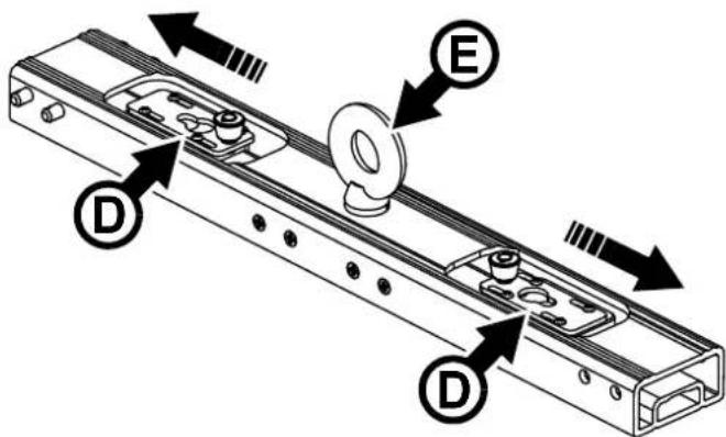
Figure 27: Opening locking plates in Single Header
-
See Figure 27. On the header, slide the locking plates D away from the suspension eye E.
-
Lift the first panel up to the header and pass the vertical connection posts A in the top of the panel up through the locking plates D in the header.
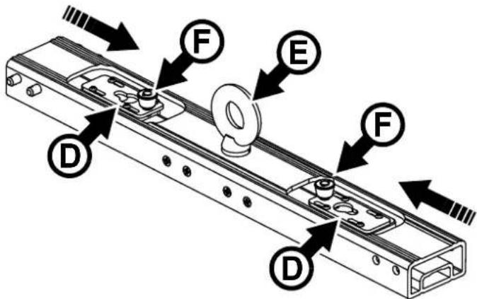
Figure 28: Closing locking plates in Single Header
-
See Figure 28. While supporting the panel, slide the locking plates D in the header towards the suspension eye E so that the locking plates engage in the grooves in the vertical connection posts A. Make sure that the locking plate knobs F click into the locked position so that the locking plates are no longer able to slide from side to side. Check that both locking plates are now latched onto the vertical connection posts.
-
See Figure 29. In the top of the panel, turn the locking levers B on both the vertical connection posts A to the Locked position G.

Figure 29: Locking vertical connection posts


Figure 30: Closing lower locking plates
- See Figure 30. Open the lower locking plates H in the bottom rail of the first panel.
- Move the vertical connection posts A in the second panel to the Unlocked position C. Lift the second panel up to the first panel and pass its vertical connection posts through the holes I in the bottom of the first panel.
- Push the locking plates H in the bottom of the first panel to the locked position J so that the plates engage in the grooves in the vertical connection posts. Make sure that the locking knob at J clicks into place so that the locking plates can no longer be opened. Check that the second panel is securely attached to the first panel.
- See Figure 29. In the top of the second panel, turn the locking levers B on the vertical connection posts A to the Locked position G.
- Continue fastening panels together in a vertical column, using the procedure described above to guide you. Make sure that all panels are securely and tightly locked together, and that locking plates cannot move to the open position.
Fastening panels side by side
To fasten VDO Face panels side by side when building a video wall:
-
See Figure 31. Note the position of the hole O in the side of the panel that acts as a receptacle and accepts the side-to-side locking bar.
-
Warning! Check that the weight of the panels to be fastened together is supported vertically. Do not use side-by-side fasteners to support the weight of panels.

natural_image
Interior view of an electronic device showing internal components and a circular annotation with an arrow (no readable text or symbols)Figure 31: Hole for side-to-side locking bar

natural_image
Close-up of a mechanical assembly with a metallic tool and textured surface (no visible text or symbols)

natural_image
Close-up of a mechanical component with a labeled arrow pointing to a component (no readable text or symbols)Figure 32: Side-to-side panel fastening
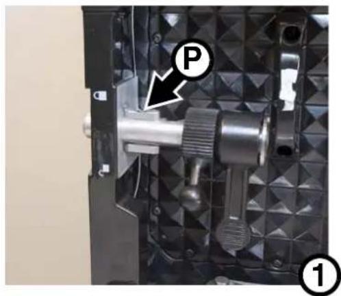
- See Figure 32. with the two panels in position beside each other, push the first panel's side-to-side locking bar P out through the panel side rail and into the hole O in the second panel so that it is at position Q in photo 2 (the second panel is not shown in the photos so that the locking bar bayonet mechanism can be seen more clearly).
- Turn the side-to-side locking lever R up to the Locked position to lock the bayonet mount S into the hole in the second panel.
- Turn the side-to-side tightening lever T up to the Locked position to tighten the bayonet mount and lock the panels tightly together.
Securing the bottom of columns against lateral movement
After installing columns of panels, secure them against lateral movement by passing sturdy cable, straps or webbing through the holes in the bottom of the bottom row of panels and fastening to a fixed anchoring point.
Warning! Do not apply stress to panels or increase the load on supporting hardware by applying downwards tension to the bottom row of panels.

Flying panels in a curved array
To suspend an array of VDO Face 5 ^TM video panels vertically to form a curved display surface, see below. To suspend array of VDO Face 5 ^TM video panels vertically to form a flat display surface, see “Flying panels in a flat array” on page 23.
It is possible to create a suspended array of VDO Face 5 ^TM panels that has a 5° or 10° concave or convex curve. In a curved array you must:
- suspend panels from VDO Face Curving Headers instead of standard VDO Face headers,
- suspend each VDO Face Curving Header correctly from its eyebolt,
- fasten panels at corners using VDO Face Curving Alignment Plates instead of the standard corner connection plates, and
- ignore the side-by-side locking bars in the sides of panels (Curving Alignment Plates provide side-by-side fastening and make the locking bars unnecessary).
Curving Headers and Curving Alignment Plates can be ordered from your Martin® supplier (see "Accessories" on page 51). Curving plates are available in sets of 10.
Installing Curving Headers

Warning! The connection plates at the ends of VDO Face Curving Headers are for alignment purposes only. Only fasten panels to a header if the header is suspended using its eyebolt as described in this user manual.
The side-by-side alignment angle of VDO Face Curving Headers is adjustable to cater for 5^ and 10^ curves. You can also use Curving Headers to align panels without creating a curve (i.e. at an angle of 0^ ).
See Figure 33. Curving Headers are similar to standard VDO Face Headers (see Figure 20 on page 23) but Curving Headers have connecting plates at each end that allow accurate side-by-side alignment. To connect Curving Headers:
- Remove the Allen head pivot bolt A and clamp screw B from the lower plate on the first header.
-
Place the upper plate C of the second header over the lower plate so that the holes are in alignment and screw the pivot bolt A and clamp screw B loosely into the lower plate so that the two Curving Headers are loosely joined together.
-
Line up the angle markings D on the upper plate of the second header with the alignment line E on the lower plate of the first header to set the two Curving Headers at a 5^ or 10^ angle to each other. To install panels in a straight line, set the Curving Headers at a 0^ angle.

Figure 33: VDO Face Curving Header
- Tighten the clamp screw B by hand and tighten the pivot screw A with an Allen key (hex wrench). Do not overtighten – the curving alignment plates (see next section) will provide the necessary rigidity in the array.
Curving Alignment Plates
When you create a curved array, you must secure panels with VDO Face Curving Alignment Plates instead of the corner connection plates shown in Figure 22 on page 25.
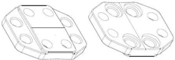
See Figure 34. VDO Face Curving Alignment Plates are available in two versions:
- Part Number 91616084 lets you suspend panels in a concave or convex 5^ curve.
- Part Number 91616085 lets you suspend panels in a concave or convex 10^ curve.
5 degree curving plate, P/N 91616084
natural_image
Technical line drawings of two octagonal mechanical components with circular holes (no text or symbols)10 degree curving plate, P/N 91616085

natural_image
Technical line drawing of two 3D mechanical components with circular holes, no text or symbols presentFigure 34: Curving Alignment Plates
To install curving plates, you must bolt them to all four panels at all the corners where four panels meet. Curving plates mount in different orientations depending on whether you are creating a convex or concave curve. See Figure 35:
- To create a convex array, install curving plates in a vertical orientation with their convex angled side facing towards the panels as shown on the left.
- To create a concave array, install curving plates in a horizontal orientation with their concave angled side facing towards the panels as shown on the right.
When you install curving plates, do not try to fasten panels together with side-to-side locking bars. The curving plates fasten panels together with enough strength to provided rigidity to the array.
Concave arrayConvex array

natural_image
Close-up of mechanical components mounted on a dark frame with no visible text or symbols
natural_image
Close-up of mechanical components with no visible text or symbolsFigure 35: Curving plate orientation
If you are using Curving Headers fastened together at a 0^ angle so that you can fasten panels together in a straight line, do not use the curving plates shown above. Instead, fasten panels together as described in “Fastening panels side by side” on page 34, and fasten corners using the standard corner connection plates shown in Figure 22 on page 25.
Suspending panels in a curved array
Warning! When creating a curved flying array of VDO Face 5™ panels, observe the safety limits (including the maximum number of panels that you can suspend in a vertical column) given in the section ‘Flying panels in a flat array’ starting on page 23. Observe these safety precautions:
- Suspend each VDO Face Curved Header using its eyebolt.
- Do not use a Curved Header to support any other weight than a column of VDO Face 5^TM panels suspended directly below that header.
• Install Curving Alignment Plates at every point where two or more panels meet.
To suspend panels in a curved array:
-
Check that the structure you will suspend the array from is capable of supporting ten times the weight of all the items that it will support.
-
Obtain one VDO Face Single Curving Header for each column of panels in the array, and obtain one VDO Face Curving Alignment Plate for every two panels in the array.
-
Suspend the Curving Headers in a curve from the truss or other supporting structure. Suspend each header from its central eyebolt using a cable or chain that is approved to support ten times the total weight of the header and all the items that will hang from it. Each eyebolt must have its own cable: do not loop one cable through more than one eyebolt. Make sure that there is no slack in cables: all cables must be equally tight. Each time you add a header, fasten it to the previous header, creating a 5° or 10° curve and setting the angle plate as described under “Installing Curving Headers” on page 36.
-
Install panels one by one in rows under the headers as described in "Instructions for suspending panels" on page 32. Each time you add a panel, fasten it to the header or panel above it using both its vertical fastener posts, then fasten it immediately to any panels that are beside it using curving alignment plates as described in "Curving Alignment Plates" on page 37.

In a flat array of panels, it is possible to leave out some corner connection plates, but in a curved array of panels, you must bolt curving alignment plates into all the corners where two or more panels meet. At the edges of the array where only two panels meet you can use either Corner Connection Plates or Curving Alignment Plates to fasten the corners together.
- Do not create a column of VDO Face 5 ^TM panels that is more than fourteen (14) panels high.
- Attach the array to anchoring points at its lower corners to make it impossible for the bottom of the array to move. Do not apply downward force to the array when attaching it.
Securing the bottom of columns against lateral movement
After installing columns of panels, secure them against lateral movement by passing sturdy cable, straps or webbing through the holes in the bottom of the bottom row of panels and fastening to a fixed anchoring point.

Warning! Do not apply stress to panels or increase the load on supporting hardware by applying downwards tension to the bottom row of panels.
Dismantling a flying installation

Warning! When dismantling a suspended column of panels, start at the bottom and work upwards, removing one panel at a time. Make sure that each panel is supported vertically before you release its side-to-side fasteners. Support the weight of each panel so that it cannot fall before you release its vertical fasteners.
Important! Avoid shocks to the edges of panels.
When tearing down an installation, remove single panels one at a time starting at the bottom of the column and working upwards.
To unfasten panels from each other, follow the instructions for fastening in reverse, but respect the following guidelines:
- Release each panel's side-to-side fasteners before you release the panel's vertical fasteners.
- Support the weight of each panel by hand before you release its vertical fasteners.
- Lift up locking buttons on vertical fastening plates before moving them to release vertical fastening posts.
- Reinstall rubber caps over connectors immediately when you disconnect a panel. This will protect connectors from moisture and damage.
AC power

Warning! The safety of the installation is the responsibility of the installer. Read 'Safety Information' starting on page 6 before creating an installation or connecting an VDO Face 5 ^™ panel to AC mains power. Disconnect the entire installation from power before working on it.

Warning! Connect to AC mains power at 100-240 VAC, 50/60 Hz only.
Warning! When you connect VDO Face 5 ^™ panels using power input and throughput connectors to form one chain that draws power via the first panel's input connector, you must not exceed a total current draw of 20 A for the chain. If you do not respect this limit you will overload cables and components and create a serious safety hazard. If you reach the maximum permitted current draw for a chain of panels and you want to supply more panels with power, you must create a new chain that draws power from a separate power outlet.
Warning! For protection from electric shock, the panel must be grounded (earthed). Power distribution circuits must be fitted with a current overload fuse or circuit breaker with a maximum rated current of 20 A and ground-fault (earth-fault) protection of high breaking capacity ( ≥ 1500 A).
Warning! The rubber caps attached to connectors must remain installed at all times on any unused power and data connectors.
Important! Connect the panels in the installation and the P3 System Controller to AC mains power at the same outlet point in the power distribution circuit, or you may experience ground/earth loop problems or create differences in potential that can damage devices. Damage caused by differences in potential if devices are incorrectly connected to power is not covered by the product warranty.
Voltage range
VDO Face 5 ^™ panels feature an auto-sensing switch-mode power supply that accepts 100-240 V nominal AC mains power at 50 or 60 Hz. Connect the panel to AC mains power that is within this voltage range only.
The VDO Face 5 ^TM can be supplied with AC mains power by connecting to one of the following three-wire systems:
- a single-phase 100-240 V system (live, neutral, ground/earth), or
- two phases of a 3-phase delta or split-phase mid-point neutral system (phase, phase, ground/earth) to obtain 200-240 V
Power figures are given under “Electrical” on page 50. Allow a sensible safety margin when calculating the current headroom required on AC mains power distribution circuits for an VDO Face 5 ^™ installation.
Power connections
The VDO Face 5 ^™ panel has Neutrik PowerCON TRUE1 connectors for power input and power throughput to the next panel in a chain.
Power input connectors are located at the bottom of panels and power throughput connectors at the top of panels (see "Overview" on page 12).
We recommend that you shut down power to the installation before connecting or disconnecting the system when possible, but if a power shutdown is not possible or difficult, the TRUE1 power connectors used in the VDO Face system are designed to withstand hot-plugging.
Power plugs and power outlet sockets
A power plug can be installed on the installation's power input cables to make it easier to connect panels to AC mains power outlets. If you choose to install a power plug, use an industrial grounding-type (earthed) 3-prong type B plug (see Figure 36) that complies with IEC 60309 or a comparable national standard and is rated 250 V, 20 A minimum. For outdoor or humid location use, the plug must also be IP67-rated. For indoor use, the plug may be IP44-rated.
Use corresponding power outlet sockets. Follow the plug and socket manufacturer's instructions and all locally applicable laws and electrical safety codes.

Figure 36: Industrial 20 A, 250 V IEC 60309 type B power plugs
When installing a power plug on the power input cable for connection to a single-phase system at 100 - 240 VAC, 50/60 Hz:
- Connect the green/yellow ground (earth) conductor to the terminal marked ⏻ or ⊥ for connection to ground (earth)
- Connect the blue conductor to the terminal marked N for connection to neutral
- Connect the brown conductor to the terminal marked L for connection to live
When installing a plug on the power input cable for connection to two phases of a 3-phase delta or split-phase mid-point neutral system to obtain 200-240 VAC, 50/60 Hz:
- Connect the green/yellow ground (earth) conductor to the terminal marked ⏻ or ⊥ for connection to ground (earth).
- Connect the blue conductor to the terminal marked N or Phase 1 or L1 for connection to one of the three phases in the system
- Connect the brown conductor to the terminal marked L or Phase 2 or L2 for connection to another of the three phases in the system
Table 1 gives details of standard wiring color codes and common pin identification symbols. If you have any doubts about proper installation, consult a qualified electrician.
| Wire color (EU) Wire color (US) | Pin (single-phase system) | Pin (3-phase system) | Symbol | |
| blue white neutral phase 1 | N | |||
| brown black live phase 2 | L | |||
| yellow/green | green | ground (earth) | ground (earth) | + or - |
Table 1: Wire colors and pin identification
Inrush current and earth leakage
The earth leakage current of one VDO Face 5 panel (under normal conditions, i.e. with no live or neutral fault) is 1.25 mA. The typical half-cycle RMS inrush current of one VDO Face 5 panel (again under normal conditions, i.e. with no live or neutral fault) is 7.9 A.
When multiple VDO Face 5 panels are connected in a chain on the same power line, the combined ground (earth) leakage and inrush currents can be high enough to trip the line's residual current circuit breaker (RCD, RCCB, RCBO) when powering on. The fact that residual current breakers often trip at a significantly lower ground leakage current than their nominal rating increases the probability that a breaker may trip unexpectedly. If a breaker trips, substituting with a different breaker may solve the problem. But in some cases the only solution is to reduce the number of video panels per daisy chain to less than the maximum permitted number that is specified for the product. To minimize any possible inconvenience, we recommend that you allow a generous margin when planning number of panels per circuit breaker.
Fuses

Warning! Fuses are not user-replaceable. Contact a Martin® authorized service agent for assistance if you suspect that a fuse has blown.
P3 communication link
VDO Face 5 ^™ panels communicate using the Martin® P3 signal format (Ethernet Martin® P3 Protocol). The P3 signal contains both video data and command signals.
VDO Face 5 ^™ panels have integral P3 data input and throughput connectors on the back of panels (see “Overview” on page 12).
It is possible to mix and interconnect different Martin® LED video products in an installation. The P3 System Processor will recognize the products in the installation, display them correctly in the user interface, and control the different products correctly.
Cable and connector types
Use good-quality CAT 5e or better STP (shielded twisted pair) Ethernet cable for the P3 link. Cable must be suitable for the installation environment. RJ-45 connectors should be shielded type, with the shield around the connector terminals electrically connected to the cable shield.
The Ethernet socket on each panel has a sealing cap and accepts IP65-rated Neutrik EtherCON Cat 6 push-pull connectors. We recommend use of the IP65-rated Neutrik EtherCON CAT 6 cables supplied by Martin® for the VDO Face 5™ (see "Data cable" on page 51).
In an indoor environment only, you can use non-IP-rated standard RJ-45 Ethernet connectors. It is possible to make your own cables with Neutrik EtherCON Cat 6 connectors.
Unused connectors on panels must be sealed with their supplied rubber caps at all times.
Planning the P3 link
Figure 37 on page 44 shows an example of a P3 system layout.
Martin P3 System Controllers accept a wide variety of video signal types. Please refer to product documentation for details.
P3 link requirements in large installations
A single P3 network can contain up to 520 000 pixels, corresponding to maximum of 50 x VDO Face 5 ^TM panels. Please see the P3 System Controllers documentation for details of how many P3 networks and pixels each of the various P3 System Controllers can control.
If an installation consists of more than 50 x VDO Face 5 ^TM panels, it can be split into two and two P3 System Controllers used in tandem. An even easier solution is to use a P3-300 System Controller. This controller has four P3 network outputs, each of which can drive up to 520 000 pixels.
Using Ethernet switches to split the link into chains
To make cabling more convenient, you can run the P3 signal output from the P3 System Controller to a 1 GB Ethernet switch, then use the outputs from the Ethernet switch to send the P3 signal to groups of panels. You can insert an Ethernet switch at any point on the link to branch the link into separate daisy chains.
Using Ethernet switches to extend the link
See Figure 37. The maximum permitted cable length between any two devices on the P3 link before a signal amplifier is required is 100 m (328 ft.) if good quality Ethernet cable is used for the link. A 1 GB Ethernet switch on the P3 link is an ideal signal amplifier. If the P3 link will exceed the 100 m cable length limit at any point in the installation, insert an Ethernet switch to boost the signal. If necessary, more switches can be added each time the link reaches the 100 m limit.
Figure 37 shows the 1 GB Ethernet switch inserted between two panels on the P3 link as an example only: the switch can be inserted in any position on the link where the cable length between any two devices would exceed 100 m.
Important! More expensive, sophisticated switches tend to carry out additional processing that can cause latency. You should therefore choose a relatively cheap unmanaged 1GB Ethernet switch.
P3 system layout: schematic overview

flowchart
graph TD
    A["Media server"] -->|DVI| B["P3 System Controller"]
    C["Analog video"] -->|Analog video| B
    D["DVD"] -->|Analog video| B
    B --> E["P3 signal"]
    E --> F["Monitor"]
    F --> G["Keyboard"]
    G --> H["Mouse"]
    H --> I["1GB Ethernet switch"]
    I --> J["Display panel"]
Figure 37: Schematic diagram of P3 system connections
Connecting the P3 link

Warning! In outdoor or humid environments, use only Neutrik EtherCON Cat 6 connectors for P3 signal connections, or panels will not be weatherproof to IP65. We recommend use of the cables supplied by Martin® for the VDO Face 5™ (see “Data cable” on page 51).
To connect the P3 link:
- Run an Ethernet cable from the P3 System Controller's P3 signal output to an input on a 1GB Ethernet Switch.
- Run an Ethernet cable from the Ethernet Switch to the Data IN connector on the first panel in the chain.
- Run an Ethernet patch cable from the first panel's Data THRU connector to the Data IN connector of the next panel in the chain and continue connecting panels, Data THRU to Data IN in a daisy-chain. A maximum of 50 panels may be connected in one chain.
- If necessary, connect additional chains to the P3 System Controller, running Ethernet patch cables from the Ethernet Switch outputs to the data input of the first panel on each chain. Respect the layout and guidelines given earlier in this section.
- Keep all unused panel connectors sealed with their rubber caps at all times.
- The system is now ready for power to be applied.
- Set up the panels to display video as described in the P3 System Controller's user manual.
Operation

Warning! Read 'Safety Information' starting on page 6 before operating an VDO Face 5^TM system. Note in particular that panels must be removed from an installation under certain wind conditions.
This section explains the options available for testing and resetting VDO Face 5 ^™ panels, but it does not explain how to position panels in the video image or video display options. For details of these, see the user documentation supplied with the P3 System Controller or available for download from www.martin.com
When repacking panels in a Martin® flightcase after operation, follow the instructions in the flightcase (see "Avoiding damage to panels" on page 11).
Monitoring status and testing
Status indicator and test/reset button
See Figure 38. Status can be checked, panels can be tested and panels can be reset without a P3 System Controller using the test/reset button and status indicator LED on the back of the panel.
Testing LEDs and panels
Press the test/reset button once briefly. The panel will display a test pattern so that you can check for correct LED operation. Press the test/reset button once briefly again to display the next test pattern in the test sequence. Continue until all test patterns have been displayed.

Figure 38: Test/reset button and status indicator LED
RGB status indicator LED
The RGB status LED gives an indication of panel status. This LED indicates the following states:
Color Output Indication Action required
| Blue Constant | Busy (e.g. booting up or writing to flash memory). | Wait a moment for normal operation to be resumed. | |
| Red Constant | Error. The panel has encountered a fatal error and can not run. | Perform a factory reboot, followed by a firmware upload. | |
| Red Flashing | Disconnected. A system controller could not be found. | Connect a system controller to the network. | |
| Green Flashing | Ready. A system controller is present on the network. | Configure the system controller to use this panel. | |
| Green Constant | Running. A system controller is using this panel. | None. |
Table 2: RGB status LED
Resetting and rebooting panels
If it becomes necessary to reset an VDO Face 5™ panel, it is possible to force a 'normal reboot' (which causes the panel to reset and start up as it normally would when power is applied), or a 'factory reboot' (which causes the panel to start up the original factory-programmed firmware). The factory reboot is a fail-safe way to ensure the panel can be started up if there is a problem with the most recently uploaded firmware. It should not be required during normal operation.
Normal reboot: Press the test/reset button for approx. 3 seconds until the status LED lights blue. Release the button. The panel will boot normally as though power has just been applied.
Factory reboot: Press the test/reset button for approx. 8 seconds until the status LED lights white. Release the button. The panel will then boot using the original factory-programmed firmware.
Note that performing a factory reboot will only cause the panel to boot the factory firmware once. At the next power cycle (or reset), a normal reboot will be carried out.
Service and maintenance

Warning! Disconnect the panel from power or isolate the entire distribution circuit from power and ensure that all unused connectors are sealed with the supplied rubber caps before cleaning.
Warning! Refer any service operation not described below to a service technician approved by Martin Professional™. Removing any cover may cause a safety risk or unsatisfactory performance and will invalidate the product warranty.
Important! If you need to put VDO Face 5 ^™ panels LED-side down, place them on a soft, flat surface only.
The user will need to carry out periodic cleaning, it is possible for the user to update the VDO Face 5 ^TM firmware from the P3 System Controller, and the user may replace LED modules. All other service operations must be carried out by Martin Professional or its approved service agents.
Installation, on-site service and maintenance can be provided worldwide by the Martin Professional Global Service organization and its approved agents, giving owners access to Martin's expertise and product knowledge. This type of partnership will ensure the highest level of performance throughout the product's lifetime. Please contact your Martin® supplier for details.
It is Martin® policy to apply the strictest possible calibration procedures and use the best quality materials available to ensure optimum performance and the longest possible component lifetimes. However, LEDs are subject to wear and tear over the life of the product, resulting in gradual changes in color and overall brightness over many thousands of hours of use. The extent of wear and tear depends heavily on operating conditions and environment, so it is impossible to specify precisely whether and to what extent LED performance will be affected. To compensate for changes in LED performance, Martin® has developed the P3 Fixture Adjuster. Please contact Martin® for details and training.
The LEDs will not be affected by weather conditions as they are sealed inside modules. However, the outer surfaces of LED modules will be exposed to the elements, dirt, dust, etc.
Storage
Store panels in a dry environment. Make sure that panels are dry before packing them in flightcases.
Cleaning
Do not use abrasive, caustic or solvent-based products for cleaning, as they can cause surface damage.
To clean a VDO Face 5 ^TM panel:
- Vacuum or gently blow away dust and loose particles from the panel with low-pressure compressed air.
- Wipe the outside of the LED modules with a soft, lint-free cloth dampened with a solution of water and detergent or auto shampoo. Apply gentle pressure only.
If panels have been used in a marine or coastal environment, clean them thoroughly to avoid the buildup of salt that can cause corrosion.
Installing new software
It may be necessary to upload new software to an VDO Face 5 ^™ panel if the product appears to have a software-related fault or if you want to update to a newer software version.
Software updates are available from Martin and can be installed from the P3 System Controller over the P3 link.
See the P3 System Controller user manual for software installation instructions.
Replacing an LED block
Important! Take care to avoid damage to LED blocks. Do not place panels LED-side down unless for service and on a soft, flat surface. Take particular care to avoid shocks to the edges of LED blocks during removal, storage and installation.
Important! LED blocks that fit the left and right-hand side of VDO Face 5 ^TM panels are different.
VDO Face 5™ video panels use a modular block LED system that allow modules to be removed and replaced for artistic or repair purposes. Modules are held in position by magnets and are hot-swappable, so they can be replaced in a matter of seconds in the middle of a show, even if power is applied and a P3 signal is present.
Blocks are supplied as either Left or Right (as viewed from the front, audience side) units and are marked LEFT or RIGHT to identify them. Install only the correct type of block on each side of the panel.
Removing an LED block
There are two methods for removing an LED block from a panel. See (A) and (B) below.
(A) If you have access to the back of the panel:
- See Figure 39. Take hold of the handle on the back of the LED block and push the block towards the front of the panel until it is disconnected from its multiconnector and released from its magnetic holders.
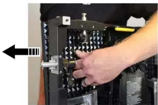
natural_image
Person installing or adjusting a mechanical component with a tool, no visible text or symbols
natural_image
Close-up of a person adjusting a mechanical device with visible wiring and components (no text or symbols)Figure 39: Replacing an LED block, rear access
- Unclip the carabiner hook (arrowed) on the LED block safety wire and lift the block away from the panel.
(B) If you do not have access to the back of the panel:
-
Obtain a VDO Face LED Block Removal Tool available from Martin® (see "Accessories" on page 51).
-
See Figure 40. Screw the prongs (arrowed) on the ends of the Removal Tool into the corresponding holes in the front of the LED block, then lift the block away from the panel.
-
Unclip the carabiner hook on the LED block safety wire and lift the block away from the panel.
Installing an LED block
To install an LED block:
-
Align the block so that the safety cable attachment bracket is pointing upwards and the multi-connector on the back of the block is pointing in towards the center of the panel.
-
Fasten the safety wire in the panel to the attachment bracket at the top of the LED block.
-
Depending on whether you have access to the front or rear of the panel, use the removal tool shown in Figure 40 or the handle shown in Figure 39 to reinstall the block. You will need to use a little pressure to reconnect the LED block's multi-connector, but do not use excessive force.
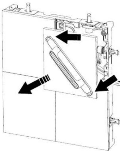
natural_image
Technical line drawing of a mechanical assembly with directional arrows indicating movement or force (no text or symbols present)Figure 40: Replacing an LED block, front access
Troubleshooting
Problem Probable cause(s) Remedy
| Panel is completely dead. | No power to panel. Check power and connections. | |
| Fuse blown. | Disconnect panel from power. Contact Martin Professional for service. | |
| Defective PSU (power supply unit). | Disconnect panel from power. Contact Martin Professional for service. | |
| One or more panels displays video incorrectly or does not display video at all. | Incorrect panel settings on P3 System Controller. | Check settings (display addresses, panel Device Properties, etc.). |
| Fault on P3 link. | Inspect connections and cables. Correct poor connections. Repair or replace damaged cables. | |
| Panel defective. | Have faulty panel serviced by Martin service technician. | |
| Other device (e.g. Ethernet switch) on P3 link defective. | Replace with a device known to be operating correctly. Have faulty device tested and serviced. | |
| All panels and/or monitor screen display video incorrectly or do not display video at all. | Incorrect video input or panel settings on P3 System Controller. | Check settings (PAL/SECAM/NTSC selection, overall panel intensity setting, etc.) |
| Unusable video signal or defective video source. | Check video source. | |
| Fault on P3 link. | Inspect connections and cables. Correct poor connections. Repair or replace damaged cables. | |
| Device on P3 link defective. | Have faulty panel or device tested and serviced by Martin service technician or supplier. | |
| Display cuts out intermittently. | Panel is too hot. | Ensure free airflow around spine.Clean spine.Check that ambient temperature does not exceed max. permitted level.Contact Martin for service. |
| Fault on the P3 link. | Inspect connections and cables. Correct poor connections. Repair or replace damaged cables. | |
| Device on P3 link defective. | Have faulty panel or device tested and serviced by Martin service technician or supplier. | |
| One LED module cuts out. | LED module incorrectly installed and connected.LED module faulty. | Check module.Replace LED module. |
Table 3: Troubleshooting
Specifications
Physical
VDO Face 5™ LED Video Panel
Width .500 mm (19.7 in.)
Height 562.5 mm (22.2 in.)
Depth 105 mm (4.2 in.)
Weight 10.5 kg (23.2 lbs.)
VDO Face Single Header
Width 500 mm (19.7 in.)
Height 36 mm (1.5 in.)
Depth 69 mm (2.8 in.)
Weight 2.4 kg (5.3 lbs.)
VDO Face Double Header
Width 1000 mm (39.4 in.)
Height 36 mm (1.5 in.)
Depth 69 mm (2.8 in.)
Weight 5.0 kg (11.1 lbs.)
VDO Face 6-panel Flightcase
Length 1200 mm (47.3 in.)
Width .580 mm (22.9 in.)
Height (including wheels)....767 mm (30.2 in.)
Weight (empty)....61 kg (134.5 lbs.)
Control and Programming
Addressing and status....Via Martin® P3 System Controller
Mapping....Via Martin® P3 System Controller
Firmware update....Via Martin® P3 System Controller
Control/User Interface
Device status Multicolor LED
Device testing and reset ....Pushbutton
Optics
Pixel pitch (LED center-to-center) 5.208 mm (0.205 in.)
Viewing angle (horizontal x vertical) 160^ × 140^
LED refresh rate 3400 Hz
Color resolution 16 bits per color (48 bits per pixel)
Resolution, one panel 96 x 108 pixels
Pixels per panel 10 368
Color and intensity calibration ....Pixel-level
LED type
VDO Face 5™ HB SMD, RGB, black housing, white reflector
VDO Face 5 ^TM HC....SMD, RGB, black housing, black reflector
Photometric Data
VDO Face 5 HB
Brightness, calibrated mode 5000 Nit
VDO Face 5 HC
Brightness, calibrated mode 3000 Nit
Video Processing
Video signal processor .... External processor from Martin® P3 System Controller range
Latency between first and last device None
Brightness control Via Martin® P3 System Controller
Gamma correction and control Via Martin® P3 System Controller
Color temperature control Via Martin® P3 System Controller
Color space control Via Martin® P3 System Controller
Calibration processing....Via Martin® P3 System Controller
Synchronization....Via Martin® P3 System Controller
For full video processing and performance data, see relevant P3 System Controller specifications
P3 Signal Protocol
Signal type....Gigabit Ethernet
Protocol Proprietary Martin® P3
Hot pluggable. . . . . . . . . . . . . . . . . . . . . . . . . . . . . . . . . . . . . . . . . . . . . . . . . . . Yes, electrically insulated at all connections
Cable type.... Ethernet, Cat 5e or better
Cable length..... Up to 100 m (328 ft.) between any 2 devices, extendable with Ethernet switch
Max. number of devices per chain ..... 50 (split and multiple chains possible with Ethernet switch)
Construction
Panel frame ....Die-cast aluminum
LED modules per panel.... 4 x quick-install, hot-swappable LED blocks
Color ....Matt black
Protection rating. IP65, NEMA 4
RoHS compliant
Installation
Orientation....Any
Location.... Indoor or non-permanent outdoor installation
Mounting ..... Vertical columns via headers, creative layouts via panel clamps
Max. suspended from VDO Face headers.....10 panels (safety factor 10) or 16 panels (safety factor 6)
Max. suspended from panel clamp (any orientation)....1 panel
Max. wind pressure suspended from VDO Face Headers. . . . . . . . . Force 8 Beaufort, 20 m/s or 45 mph
Max. stacked on VDO Face Footer system . . . . . . . . Up to 8 panels depending on installation method
Max. wind pressure standing on VDO Face Footers.... Force 2 Beaufort, 3 m/s or 7 mph
Panel interlocking. . . . . . . . . . . . . . . . . . . . . . . . . . . . . . . . . . . . . . . . . . . . . . . . . . . . Quick-lock mechanism
Connections
Power in, power thru . . . . . . . . . . . . . . . . . . . . . . . . . . . . . . . . . . . . . . . . . . . . . . . . . Neutrik PowerCON TRUE1
Data in, data thru. Neutrik EtherCON Cat 6
Electrical
AC power 100-240 V nominal, 50/60 Hz
Power supply unit....Integrated, auto-sensing multi-voltage
Inrush current (half-cycle RMS)....7.9 A
VDO Face 5 HB
Peak power consumption (approx., at full intensity, full white) ..... 191 W per panel, 679 W per m ^2
Typical power consumption (with typical video content) 64 W per panel, 226 W per m²
VDO Face 5 HC
Peak power consumption (approx., at full intensity, full white) ..... 260 W per panel, 924 W per m² Typical power consumption (with typical video content) ..... 87 W per panel, 309 W per m²
Thermal
Cooling. Convection
Maximum ambient temperature ( T_a max.), full intensity, full white. 45° C (113° F)
Minimum ambient temperature ( T_a min.) ....-20° C (-4° F)
VDO Face 5 HB
Typical total heat dissipation (calculated, per panel, with typical video content) ..... 220 BTU/hr.
VDO Face 5 HC
Typical total heat dissipation (calculated, per panel, with typical video content) .... 300 BTU/hr.
Approvals

EU safety..... EN 60950-1, EN 62311, EN 62471
EU EMC EN 55024, EN 55032, EN 61000-3-2, EN 61000-3-3
US safety (pending) .ANSI/UL 60950-1
US EMC FCC Title 15, Subpart B, Class A, ANSI C63.4
Canadian safety (pending) CSA C22.2 No. 60950-1-03
Canadian EMC ICES-003 Class A
Australia / NZ ....RCM

Accessories
Installation hardware
VDO Face Panel Connection Plate incl. bolts P/N 91616070
Extra Eyebolt Kit for VDO Face Header.... P/N 91608010
VDO Face Panel Clamp.... P/N 91616076
VDO Face Single Curving Header in cardboard box.... P/N 91616083
VDO Face Curving Plates, 5°, set of 10. P/N 91616084
VDO Face Curving Plates 10°, set of 10 P/N 91616085
Floor stand system
VDO Face Footer Base Unit P/N 91616077
VDO Face Footer Leg, Long P/N 91616078
VDO Face Footer Double Ladder P/N 91616079
VDO Face Footer Panel Connector Left P/N 91616080
VDO Face Footer Panel Connector Center P/N 91616081
VDO Face Footer Panel Connector Right P/N 91616082
Flightcase for 4 x VDO Face Footer Base Units P/N 91515049
Flightcase Extender for 5 x VDO Face Footer Legs P/N 91515050
Flightcase Extender for 10 x VDO Face Footer Ladder.... P/N 91515051
Service accessories
VDO Face LED Block Front Removal Tool.... P/N 91616067
Data cable
Data Cable, Cat 6 EtherCON-EtherCON 0.45 m (1.4 ft.). P/N 91611781
Data Cable, Cat 6 EtherCON-EtherCON 1.2 m (3.9 ft.). P/N 91611782
Data Cable, Cat 6 EtherCON-EtherCON 5 m (16.4 ft.) P/N 91611783
Data Connector, Cat 6 EtherCON P/N91611787
Power cable, EU type
Power Input Cable, H07RN-F, 2.5 mm2, bare ends to Neutrik TRUE1 NAC3FX-W (female), 1.5 m (4.9 ft). P/N 91611797
Power Input Cable, H07RN-F, 2.5 mm2, bare ends to Neutrik TRUE1 NAC3FX-W (female), 5 m (16.4 ft.) P/N 91611786
Power Relay Cable, H07RN-F, 2.5 mm2, Neutrik TRUE1 to TRUE1, 0.45 m (1.5 ft.) P/N 91611784
Power Relay Cable, H07RN-F, 2.5 mm2, Neutrik TRUE1 to TRUE1, 1.2 m (3.9 ft.) P/N 91611785
Power Relay Cable, H07RN-F, 2.5 mm2, Neutrik TRUE1 to TRUE1, 2.5 m (8.2 ft.) P/N 91611796
Power cable, US type
Power Input Cable, SJOOW, AWG 12, bare ends to Neutrik TRUE1 NAC3FX-W to bare ends, 1.5 m (4.9 ft.) P/N 91610173
Power Input Cable, SJOOW, AWG 12, bare ends to Neutrik TRUE1 NAC3FX-W to bare ends, 5 m (16.4 ft.) P/N 91610174
Power Relay Cable, SJOOW, AWG 12, Neutrik TRUE1 to TRUE1, 0.45 m (1.5 ft.) P/N 91610170
Power Relay Cable, SJOOW, AWG 12, Neutrik TRUE1 to TRUE1, 1.2 m (3.9 ft.) P/N 91610171
Power Relay Cable, SJOOW, AWG 12, Neutrik TRUE1 to TRUE1, 2.5 m (8.2 ft.) P/N 91610172
Power connectors, cable mount
Cable Connector, Neutrik PowerCON TRUE1 NAC3FX-W (female, power IN at device) P/N 91611789
Cable Connector, Neutrik PowerCON TRUE1 NAC3MX-W (male, power THRU from device) P/N 91611788
Spare Parts
VDO Face 5 HB LED Block, Left P/N 91616063
VDO Face 5 HB LED Block, Right.... P/N 91616064
VDO Face 5 HC LED Block, Left P/N 91616065
VDO Face 5 HC LED Block, Right. P/N 91616066
Related Items
Martin® P3-050 System Controller P/N 90721090
Martin® P3-100 System Controller P/N 90721010
Martin® P3-150 System Controller P/N 90721015
Martin® P3-200 System Controller P/N 90721020
Martin® P3-300 System Controller P/N 90721060
Martin® P3-PC License on One-Key™ USB stick....P/N 90721030
Martin® P3-PC License Only....P/N 39808028
Martin® P3 Fixture Adjuster License and Training. P/N 90721100
Ordering Information
Panels
VDO Face 5™ HB Panel, calibrated, in cardboard box.... P/N 90354660
VDO Face 5™ HC Panel, calibrated, in cardboard box P/N 90354670
Headers
VDO Face Single Header in cardboard box. P/N 91616061
VDO Face Double Header in cardboard box P/N 91616062
Flightcases
Flightcase for 6 x VDO Face Panels P/N 91515038
Flightcase for 6 x VDO Face Double Headers.... P/N 91515040
Flightcase Extender for 6 x VDO Face Double Headers....P/N 91515041
Specifications are subject to change without notice.
All VDO Face and P3 System Controller user documentation is also available for download free of charge from the Product Support / Tech Docs pages at www.martin.com
WARNING: Operation of this equipment in a residential environment could cause radio interference.
CAUTION: This product has been tested and found to comply with EMC (electromagnetic compatibility) standards as a single unit. Using multiple products together may have an impact on the EMC performance of the complete system, and this could cause EMI (electromagnetic interference). If this occurs, the user may be required to take appropriate measures to reduce interference.

Disposing of this product
Martin® products are supplied in compliance with Directive 2012/19/EC of the European Parliament and of the Council of the European Union on WEEE (Waste Electrical and Electronic Equipment), where applicable.
Help preserve the environment! Ensure that this product is recycled at the end of its life. Your supplier can give details of local arrangements for the disposal of Martin products.
- VDO Face 5™ Video Panel
- User Manual
- Dimensions
- VDO Face 5 Panel Clamp
- VDO Face Footer floor stand system
- Safety Information
- WARNING!
- Read the safety precautions in this section before installing, powering, operating or servicing VDO Face 5 TM products.
- PROTECTION FROM ELECTRIC SHOCK
- PROTECTION FROM FIRE AND BURNS
- PROTECTION FROM INJURY
- PROTECTION FROM INJURY CAUSED BY WIND PRESSURE
- SAFETY PRECAUTIONS FOR FLYING INSTALLATIONS
- SAFETY PRECAUTIONS FOR STACKED INSTALLATIONS
- Contents
- Safety Information....6
- Introduction 10
- Overview 12
- Physical installation 13
- AC power 40
- P3 communication link 43
- Operation 45
- Service and maintenance....46
- Troubleshooting 48
- Specifications 49
- Introduction
- Panels and flightcases
- Avoiding damage to panels
- Using for the first time
- Overview
- Physical installation
- Before installing
- Types of installation
- Installing single panels on a truss or structure
- Stacking panels on floor stands
- Safety limits with single row of stabilizer legs
- Safety limits with two rows of stabilizer legs
- Creating a stacked array
- Installing VDO Face Footer system components
- Installing VDO Face 5 panels on the Face Footer system
- Panel brackets
- Fastening panels into place
- Taking down a stacked array
- VDO Face Footer system flightcases
- Flying panels in a flat array
- Header side connection brackets
- Corner connection plates
- Single columns
- Multiple columns
- Columns that need to be stabilized
- Anchoring the bottom of columns
- Possible configurations
- Single-column arrays
- Arrays of 2 - 5 columns
- Two-column arrays
- Four-column arrays
- Three- and five-column arrays
- Larger multiple-column arrays
- Instructions for suspending panels
- Fastening panels side by side
- Securing the bottom of columns against lateral movement
- Flying panels in a curved array
- Installing Curving Headers
- Curving Alignment Plates
- Suspending panels in a curved array
- Dismantling a flying installation
- AC power
- Voltage range
- Power connections
- Power plugs and power outlet sockets
- Inrush current and earth leakage
- Fuses
- P3 communication link
- Cable and connector types
- Planning the P3 link
- P3 link requirements in large installations
- Using Ethernet switches to split the link into chains
- Using Ethernet switches to extend the link
- P3 system layout: schematic overview
- Connecting the P3 link
- Operation
- Monitoring status and testing
- Status indicator and test/reset button
- Testing LEDs and panels
- RGB status indicator LED
- Resetting and rebooting panels
- Service and maintenance
- Storage
- Cleaning
- Installing new software
- Replacing an LED block
- Removing an LED block
- Installing an LED block
- Troubleshooting
- Specifications
- Physical
- VDO Face 5™ LED Video Panel
- VDO Face Single Header
- VDO Face Double Header
- VDO Face 6-panel Flightcase
- Control and Programming
- Control/User Interface
- Optics
- LED type
- Photometric Data
- VDO Face 5 HB
- VDO Face 5 HC
- Video Processing
- P3 Signal Protocol
- Construction
- Installation
- Connections
- Electrical
- Thermal
- Approvals
- Accessories
- Installation hardware
- Floor stand system
- Service accessories
- Data cable
- Power cable, EU type
- Power cable, US type
- Power connectors, cable mount
- Spare Parts
- Related Items
- Ordering Information
- Panels
- Headers
- Flightcases
- Disposing of this product
Brand : MARTIN
Model : VDO Face 5 HC
Category : Video Conferencing System