
VSX 48 - Professional audio equipment PEAVEY - Free user manual and instructions
Find the device manual for free VSX 48 PEAVEY in PDF.


| Product Type | Digital Signal Processor / Mixer |
| Brand | Peavey |
| Model | VSX 48 |
| Dimensions (W x H x D) | 19 x 3.5 x 12 inches (rackmount, 2U) |
| Weight | 12.5 lbs (5.7 kg) |
| Power Supply | 100-240 VAC, 50/60 Hz, 40W |
| Analog Inputs | 48 balanced XLR line inputs |
| Analog Outputs | 16 balanced XLR outputs |
| Digital Audio Sampling Rate | 48 kHz |
| Bit Depth | 24-bit |
| Signal Processing | Parametric EQ, delay, compression, limiting, crossover |
| Connectivity | USB-B (firmware), RS-232, Ethernet (control) |
| Display | 2x16 character LCD backlit |
| Rackmount | 19-inch rackmountable (2U) |
| Cooling | Internal fan, variable speed |
| Operating Temperature | 32°F to 104°F (0°C to 40°C) |
| Accessories Included | Power cord, rack ears, user manual |
| Maintenance | Clean with dry cloth; avoid liquids; check air vents monthly |
| Safety | Class 1 laser product; do not open; disconnect power before cleaning |
| Spare Parts Availability | Contact Peavey authorized service centers |
| Repairability | Serviceable only by qualified technicians |
Frequently Asked Questions - VSX 48 PEAVEY
User questions about VSX 48 PEAVEY
0 question about this device. Answer the ones you know or ask your own.
Ask a new question about this device
Download the instructions for your Professional audio equipment in PDF format for free! Find your manual VSX 48 - PEAVEY and take your electronic device back in hand. On this page are published all the documents necessary for the use of your device. VSX 48 by PEAVEY.
USER MANUAL VSX 48 PEAVEY
VSX ^TM 48
Digital Loudspeaker
Processor
Operating Manual

natural_image
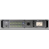
Front view of a black industrial control unit with labeled ports and buttons (no readable text beyond labels)
Intended to alert the user to the presence of uninsulated "dangerous voltage" within the product's enclosure that may be of sufficient magnitude to constitute a risk of electric shock to persons.
Intended to alert the user of the presence of important operating and maintenance (servicing) instructions in the literature accompanying the product.
CAUTION: Risk of electrical shock — DO NOT OPEN!
CAUTION: To reduce the risk of electric shock, do not remove cover. No user serviceable parts inside. Refer servicing to qualified service personnel.
WARNING: To prevent electrical shock or fire hazard, this apparatus should not be exposed to rain or moisture, and objects filled with liquids, such as vases, should not be placed on this apparatus. Before using this apparatus, read the operating guide for further warnings.

Protective earthing terminal. The apparatus should be connected to a mains socket outlet with a protective earthing connection.

IMPORTANT SAFETY INSTRUCTIONS
WARNING: When using electrical products, basic cautions should always be followed, including the following:
-
Read these instructions.
-
Keep these instructions.
-
Heed all warnings.
-
Follow all instructions.
-
Do not use this apparatus near water.
-
Clean only with a dry cloth.
-
Do not block any of the ventilation openings. Install in accordance with manufacturer's instructions.
-
Do not install near any heat sources such as radiators, heat registers, stoves or other apparatus (including amplifiers) that produce heat.
-
Do not defeat the safety purpose of the polarized or grounding-type plug. A polarized plug has two blades with one wider than the other. A grounding type plug has two blades and a third grounding plug. The wide blade or third prong is provided for your safety. If the provided plug does not fit into your outlet, consult an electrician for replacement of the obsolete outlet.
-
Protect the power cord from being walked on or pinched, particularly at plugs, convenience receptacles, and the point they exit from the apparatus.
-
Only use attachments/accessories provided by the manufacturer.
-
Use only with a cart, stand, tripod, bracket, or table specified by the manufacturer, or sold with the apparatus. When a cart is used, use caution when moving the cart/apparatus combination to avoid injury from tip-over.
-
Unplug this apparatus during lightning storms or when unused for long periods of time.
-
Refer all servicing to qualified service personnel. Servicing is required when the apparatus has been damaged in any way, such as power-supply cord or plug is damaged, liquid has been spilled or objects have fallen into the apparatus, the apparatus has been exposed to rain or moisture, does not operate normally, or has been dropped.
-
Never break off the ground pin. Write for our free booklet "Shock Hazard and Grounding." Connect only to a power supply of the type marked on the unit adjacent to the power supply cord.
-
If this product is to be mounted in an equipment rack, rear support should be provided.
-
Note for UK only: If the colors of the wires in the mains lead of this unit do not correspond with the terminals in your plug, proceed as follows: a) The wire that is colored green and yellow must be connected to the terminal that is marked by the letter E, the earth symbol, colored green or colored green and yellow. b) The wire that is colored blue must be connected to the terminal that is marked with the letter N or the color black. c) The wire that is colored brown must be connected to the terminal that is marked with the letter L or the color red.
-
This electrical apparatus should not be exposed to dripping or splashing and care should be taken not to place objects containing liquids, such as vases, upon the apparatus.
-
The on/off switch in this unit does not break both sides of the primary mains. Hazardous energy can be present inside the chassis when the on/off switch is in the off position. The mains plug or appliance coupler is used as the disconnect device, the disconnect device shall remain readily operable.
-
Exposure to extremely high noise levels may cause a permanent hearing loss. Individuals vary considerably in susceptibility to noise-induced hearing loss, but nearly everyone will lose some hearing if exposed to sufficiently intense noise for a sufficient time. The U.S. Government's Occupational Safety and Health Administration (OSHA) has specified the following permissible noise level exposures:
Duration Per Day In Hours Sound Level dBA, Slow Response
| 8 | 90 | ||
| 6 | 92 | ||
| 4 | 95 | ||
| 3 | 97 | ||
| 2 | 100 | ||
| 1 1/2 | 102 | ||
| 1 | 105 | ||
| 1/2 | 110 | ||
| 1/4 or less | 115 |
According to OSHA, any exposure in excess of the above permissible limits could result in some hearing loss. Earplugs or protectors to the ear canals or over the ears must be worn when operating this amplification system in order to prevent a permanent hearing loss, if exposure is in excess of the limits as set forth above. To ensure against potentially dangerous exposure to high sound pressure levels, it is recommended that all persons exposed to equipment capable of producing high sound pressure levels such as this amplification system be protected by hearing protectors while this unit is in operation.
SAVE THESE INSTRUCTIONS!
a) The wire that is colored green and yellow must be connected to the terminal that is marked by the letter E, the earth symbol, colored green or colored green and yellow.
b) The wire that is colored blue must be connected to the terminal that is marked with the letter N or the color black.
c) The wire that is colored brown must be connected to the terminal that is marked with the letter L or the color red.
a) The wire that is colored green and yellow must be connected to the terminal that is marked by the letter E, the earth symbol, colored green or colored green and yellow.
b) The wire that is colored blue must be connected to the terminal that is marked with the letter N or the color black.
c) The wire that is colored brown must be connected to the terminal that is marked with the letter L or the color red.
a) The wire that is colored green and yellow must be connected to the terminal that is marked by the letter E, the earth symbol, colored green or colored green and yellow.
b) The wire that is colored blue must be connected to the terminal that is marked with the letter N or the color black.
c) The wire that is colored brown must be connected to the terminal that is marked with the letter L or the color red.
a) The wire that is colored green and yellow must be connected to the terminal that is marked by the letter E, the earth symbol, colored green or colored green and yellow.
b) The wire that is colored blue must be connected to the terminal that is marked with the letter N or the color black.
c) The wire that is colored brown must be connected to the terminal that is marked with the letter L or the color red.
FCC Compliancy Statement
This device complies with Part 15 of the FCC rules. Operation is subject to the following two conditions: (1) this device may not cause harmful interference, and (2) this device must accept any interference received, that may cause undesired operation.
Warning: Changes or modifications to the equipment not approved by Peavey Electronics Corp. can void the user's authority to use the equipment.
Note - This equipment has been tested and found to comply with the limits for a Class B digital device, pursuant to Part 15 of the FCC Rules. These limits are designed to provide reasonable protection against harmful interference in a residential installation. This equipment generates, uses and can radiate radio frequency energy and, if not installed and used in accordance with the instructions, may cause harmful interference to radio communications. However, there is no guarantee that interference will not occur in a particular installation. If this equipment does cause harmful interference to radio or television reception, which can be determined by turning the equipment off and on, the user is encouraged to try and correct the interference by one or more of the following measures.
- Reorient or relocate the receiving antenna.
- Increase the separation between the equipment and receiver.
- Connect the equipment into an outlet on a circuit different from that to which the receiver is connected.
- Consult the dealer or an experienced radio/TV technician for help.


Logo referenced in Directive 2002/96/EC Annex IV(OJ(L)37/38,13.02.03 and defined in EN 50419: 2005
The bar is the symbol for marking of new waste and is applied only to equipment manufactured after 13 August 2005
Correct Disposal of this product. This marking indicates that this product should not be disposed with other house hold wastes throughout the EU. To prevent possible harm to the environment or human health from uncontrolled waste disposal, recycle it responsibly to promote the sustainable reuse of material resources. To return your used device, please use the return and collection systems, or contact the retailer where the product was purchased. They can take this product for environmental safe recycling.

The VSX 48 is a fully programmable 32-bit audio processing and loudspeaker management control system.
Considerably more powerful than similarly priced units, the VSX 48 provides a versatile and economical alternative for system designers.
Please read this guide carefully to ensure your personal safety as well as the safety of your equipment.
Features
- 5 inputs/8 outputs
- 48 kHz sample rate – 24-bit 256x over-sampled Delta-Sigma AD, DA
- USB A and B ports for memory storage and computer interface
- XLR inputs and outputs
• +24 dBu inputs and outputs - Phantom power +48V
Front Panel

Input Section
(1) MIC INPUT
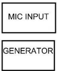
Front panel Mic or line level input. Phantom power may be selected in software. May be used as a extra input and routed through the system.
(2) DATA WHEEL
Rotate clockwise or counter clockwise to scroll through screens. Push to enter or confirm selection.
(3) LCD DISPLAY
This screen gives a graphical representation of unit configuration and parameter settings. The layout of the screen and the information displayed will depend on the function being monitored or set.
(4) Parameter Select Buttons
SETUP: Configurations are selected here. Parameter selection for inputs, signal generator, stereo/mono, routing matrix, and outputs.
EQ: parameter selection of input or output equalizers
DYNAMICS: parameter selection of input or output compressor/limiters
XOVER: parameters of the bandpass modules for each output or configured crossover
DELAY: delay time and polarity for each input or output
TOOLS: saving and loading of presets as well as default configuration
(5) Input/Output Monitoring:
LEDs indicate active or muted channel conditions. Mute switches are provided to manually mute inputs or outputs. Signal LEDs are Green for normal signal level, Yellow at +18 dBu output and Red at +20 dBu, just before the onset of clipping.
(6) USB ports:
Connection of memory stick/jump drive for preset storage and system update. The slot supports USB 2.0 memory sticks whose current draw is 150 ma or less.
NOTE: Some USB memory sticks with proprietary software may not function correctly. Make sure the memory stick is properly formatted and there are no autorun programs installed.
Rear Panel


(1) IEC POWER INPUT and FUSE HOLDER
(2) OUTPUT SECTION
XLR male line level outputs
(3) INPUT SECTION
XLR female line level inputs. Input A may be switched to AES digital input via software.
Rotate the data wheel to scroll across the screen and push the wheel to select and confirm.
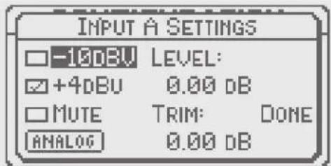
A B C & D INPUTS:
Input sensitivity switches between -10 dBV or +4 dBV inputs. The +4 dB position should be considered the "normal" position and should be used with professional systems. The -10 dB position allows the unit to be driven with "hi-fi" level equipment or directly from a CD player. The input signal must be from a balanced source.
Mute toggle on/off.
Analog/digital operation is selectable on input A.
Level controls digital processing headroom and is adjustable from 0 dB through -100 dB. This adjustment is best left as high as possible but may be adjusted as necessary.
Trim is variable from -6 dB to +6 dB and is used to match analog input sensitivity as necessary.
Exit this screen by selecting "Done" and pressing the data wheel or pressing the "setup" button.
ST/M:
Toggles between Stereo and Mono. Selecting Stereo associates the A/B channel inputs. It does not affect the output channels. When engaged in "stereo" adjusting a parameter on channel A will make a corresponding adjustment on Ch B as well as C and D inputs (when they are in stereo). This may be most useful when adjusting PEQs, Delay or Dynamic settings. Preliminary adjustments can be made to both channels in this manner and then the switch can be toggled to mono allowing further independent adjustment of single inputs. The switch may be toggled again to link up the dynamic sections for stereo tracking of the comp/limiters.
MIC:
Allows engaging the +48 V phantom power as well as adjusting the Mic gain range from 23 dB to 67 dB of gain. Select "done" or press "setup" to escape to the main screen.

flowchart
graph TD
    A["A"] --> B["B"]
    B --> C["ST"]
    C --> D["C"]
    D --> E["D"]
    E --> F["MIC"]
    F --> G["GEN"]
    G --> H["SETUP"]
    H --> I["1"]
    H --> J["2"]
    H --> K["3"]
    H --> L["4"]
    H --> M["5"]
    H --> N["6"]
    H --> O["7"]
    H --> P["8"]

GEN:
This screen selects the parameters for the signal generator. Pink, White or Sine may be selected. When Sine is selected the frequency of the sine wave may be adjusted for 20 Hz to 20 kHz. The output level may be adjusted by highlighting the fader graphic and adjusting the Level control. An In/Out button is provided to turn on and off the generator. The screen may be exited by selecting "done" or pressing the "setup button. The Generator must be assigned to an output of your choice with the Matrix. A single Band pass filter can also be assigned to that output and the skirts may be adjusted to provide limited bandwidth noise for testing purposes. It is recommended that you reduce the level to -60 dB before engaging 54 gen functions.

MATRIX:
The matrix provides the method to assign inputs to outputs. In the default configuration NO SIGNAL IS PASSED through the unit until some selection in the matrix is made. This prevents potentially destructive signals from reaching the wrong outputs. The inputs are represented by the rows and the outputs by the columns. Most users will commonly assign crossovers in the setup screen so that only a single input assignment will be necessary. In addition to the line input this screen. To continue from the matrix you must exit from the upper left

flowchart
graph TD
    A["Input Signal E"] --> B["Grid"]
    C["Input Signal C"] --> B
    D["Input Signal D"] --> B
    E["MIC"] --> B
    F["GEN"] --> B
    B --> G["Output 1"]
    B --> H["Output 2"]
    B --> I["Output 3"]
    B --> J["Output 4"]
    B --> K["Output 5"]
    B --> L["Output 6"]
    B --> M["Output 7"]
    B --> N["Output 8"]

Setup/Configuration Screen
SETUP:
Selecting this button takes you to the preset configuration page. The VSX™ is pre-programmed with fourteen configuration templates representing the most frequently used crossover possibilities. As you scroll through the configuration presets you will see and can adjust the basic filter types (only symmetrical choices may be made here). Center frequencies of those filters and a graphic representation of the filters will be displayed. You must enter "OK" to accept the selection. Selecting and pressing Exit or pressing the Setup button will return you to the main screen. Upon returning to the main screen you will see the graphic representation of your selection.
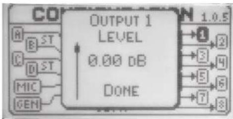
OUTPUT 1-8:
Output levels may be adjusted on this page. Press "done" or push the setup button to return to the main screen.

EQ Screen
Inputs or outputs should be selected on the top of the screen. While on the top of the screen push the data wheel and an arrow appears. Rotate the wheel to select which input or output you wish to adjust.
PARAMETRIC EQs on inputs:
Inputs A thru D display a graphical representation of the six parametric EQs that are available on each input.
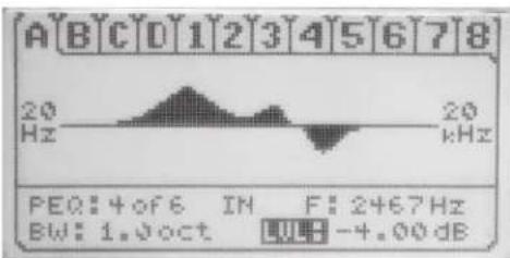
BW: Bandwidth (in oct.)
F: Frequency being adjusted.
LVL: Level control. After selecting a frequency, rotating the data wheel allows boosting or cutting the amplitude of the selected frequency +/- 15 dB in .5 dB increments.
Tip: Pressing the EQ button is a short cut to return to the top of the screen.

EQ Screen
OUTPUT EQUALIZERS
Select 1-8 on the top of the EQ screen.
FILTER:
Select any of the five independent filters to use.
TYPE:
Choices are: Parametric, Notch, Allpass1, Allpass2, Horn EQ, LPF-6, LPF-12, HPF-6, HPF-12, Low Shelf, High Shelf and Bandpass. Depending on the filter selected various options for adjustment are presented in the window.
Parametric: Frequency, BW (in oct), Level
Notch: Frequency, BW (in oct). Notch has a fixed attenuation on minus infinity and the BW is defined 3 dB from unity.
All Pass1: Frequency
All Pass2: Frequency and Bandwidth
Horn EQ: Turnover Frequency and Level
LPF6 and HPF6: Frequency Low or High Pass Filter
LPF12 and HPF12: Frequency and Q
Low and High Shelf: Frequency and Level
Bandpass: Center Frequency and Bandwidth


Dynamics
DYNAMICS:
Inputs A B C & D or outputs 1-8 should be selected on the top of the screen. While on the top of the screen push the data wheel and an arrow appears. Rotate the wheel to select which input or output you wish to adjust and press the data wheel. Dynamics in the input channels may be linked in pairs for stereo tracking on the Input pages on the Setup/Configuration screen. Most users should use the dynamics on the outputs as Limiters to protect speakers and amplifiers and as compressors on the inputs should this type of tonal modification be necessary.
THRESHOLD:
The threshold is adjustable in .5 dB steps from -76 dBu to +24 dBu. This control determines the minimum level when the compressor begins to limit the dynamic range. The compressor has no effect on the signal as long as the signal strength is below the threshold point. Once it passes the threshold point, the compressor begins to limit the dynamic range of the output according to the value set by the Ratio control.
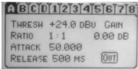
RATIO:
The ratio determines how strong the limiting becomes once the threshold is crossed. Values of 1:1 (no compression) to 20:1 are possible. Ratios of 10:1 and above should be selected for speaker protection.
ATTACK:
The attack function sets the amount of time for the compressor to respond once the threshold has been crossed. Specifying this value allows the user to determine whether the compressor responds as a peak or RMS unit as very short attack times consider only peaks while times above 50 ms average these peaks and result in RMS response. We recommend attack times of between 50 ms - 100 ms be used when setting the limiters to protect the speakers from being overdriven by the power amps. It is the average power long term that causes speaker burn out. The transient peaks usually cause little damage if kept inside the speaker's band limits.

Dynamics
RELEASE:
The Release value sets the amount of time for the compressor to recover from the compressed state once the level falls below the threshold level. We recommend release times of 5x to 10x the Attack time in normal use.
GAIN:
This adjustment serves to compensate for the loss in average signal strength due to compression. The range is -100 dB to +30 dB.
IN/OUT:
This button toggles to bypass the dynamics section.
XOver Screen
The output channel numbers appear across the top of the screen. Depending on the configuration template chosen they may appear together as blocks representing 2-way, 3-way or 4-way crossovers or singly as a Bandpass filter. After making a selection rotate the data wheel to adjust parameters.
Each bandpass filter associated with the crossover is represented graphically on the screen. The two slopes represent the lower and upper frequencies of the bandpass and the plateau represents the level of the bandpass. The intersection of slopes represents the electrical crossover point(s).
TYPE:
Available filters are: Flat, Butterworth 6, 12, 18, 24, 30, 36, 42, and 48 dB/oct.; Bessell 12, 18, 24, 30, 36, 42 and 48 dB/oct; Linkwitz-Riley 12, 24, 36 and 48 dB/oct. The user is free to mix and match filter types to create symmetrical or asymmetrical crossovers.
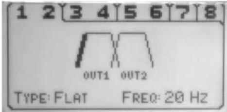
FREQUENCY:
The VSX ^™ is a very powerful tool and as such the frequency points are independent, allowing over-lapping or under-lapping as the system may require. The lowest and highest slopes in the chain are useful as high and low system cutoff filters to prevent low frequency rumble and speaker over excursion
as well as high frequency interference. The filter points are selectable in 1 Hz steps from 20 Hz to 20kHz. They may also be selected in the setup/configuration screen.
LEVEL:
The levels of the crossover sections are independently adjustable from -15 dB to +15 dB in .5 dB steps. Move the indicator to the plateau and the level parameter appears.

Delay Screen
Inputs A B C & D or outputs 1-8 should be selected on the top of the screen. While on the top of the screen push the data wheel and an arrow appears. Rotate the wheel to select which input or output you wish to adjust. Push the data wheel to accept. Normally the output delays are used to align the phase response of the drivers in a system while the input delays are useful for adding delay to the entire system(s).

IN/OUT:
Toggles to engage or bypass the delay
NORM/REVERSE:
Toggles to invert the polarity from the present state. It may become necessary to flip the polarity many times while adjusting the delay time or adjusting the cut-off rate of the filters. It is conveniently located on this page for that purpose.
DELAY:
Adds delay to the selected input or output. The delay is displayed in milliseconds, feet and meters and automatically calculates each as the data wheel is rotated. The range of each delay is 340 ms, 379.09 feet and 115.59 meters. The input delay amount will be added to the output delay amount for a possible 680 ms, 758.18 feet and 231.18 meters should a very long delay be necessary. One example would be for use with delay towers.
Tools

IMPORTANT - WHEN LOADING NEW PRESETS FROM MEMORY STICK BE SURE TO MUTE ALL OUTPUTS AND TURN YOUR POWER AMPLIFIERS DOWN OR OFF. CORRUPT DATA CAN CAUSE UNDESIRABLY RESULTS THAT COULD POTENTIALLY DAMAGE YOUR SPEAKERS.

SAVE PRESET
Allows saving the current configuration to one of 8 internal memory positions or to an external USB memory stick. If external USB is selected the VSX™ will automatically write a folder and file to the stick without disturbing other files/folders that may be present on the stick. It is not necessary to dedicate a memory stick to the exclusive service of the VSX. However, large memsticks with a lot of files may take a very long time to access. Files from the stick may be transferred to a PC or MAC computer.

Note: Configuration presets are stored in the folder: VSX48/presets on the memory stick.
NAME:
Selecting this function opens a alpha numeric keyboard. The VSX allows 8 characters to name the file. The {Right Arrow} button on the bottom right returns to the Save screen.
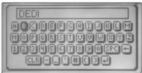
OK:
Must be selected and the data wheel pushed to actually save the preset. You will be asked to confirm this on the next screen.

LOAD PRESET:
Rotate the data wheel to select from the eight internal presets and from an external memory stick, if it is plugged in. Press OK and it will load the preset to the current preset. A confirmation screen will appear before overwriting the current preset.
INSTALLING SOFTWARE UPDATES:
Press and hold in the data wheel while powering up. Insert a memory stick. The VSX will search for files and will display a list. Select the desired version by highlighting it and press the Data Wheel. A confirmation screen will appear. Cursor over to "yes" and press the Data Wheel. The VSX will automatically perform the upgrade from here. When downloading the upgrade from the web place it in a folder: VSX48/firmware. The upgrade file will be a .bin file.
VSX ^TM 48
BLOCK DIAGRAM

flowchart
graph LR
    A["A"] --> B["6 PEQ"]
    B --> C["COMP"]
    C --> D["DLY"]


flowchart
graph LR
    B --> 6PEQ
    6PEQ --> COMP
    COMP --> DLY

flowchart
graph LR
    C --> 6PEQ
    6PEQ --> COMP
    COMP --> DLY


flowchart
graph LR
    D --> 6PEQ
    6PEQ --> COMP
    COMP --> DLY

flowchart
graph LR
    A["MIX"] --> B["BP"]
    B --> C["5 PEQ"]
    C --> D["COMP"]
    D --> E["DLY"]
    E --> F["OUT"]

flowchart
graph LR
    A["MIX"] --> B["BP"]
    B --> C["5 PEQ"]
    C --> D["COMP"]
    D --> E["DLY"]
    E --> F["OUT"]

flowchart
graph LR
    A["MIX"] --> B["BP"]
    B --> C["5 PEQ"]
    C --> D["COMP"]
    D --> E["DLY"]
    E --> F["OUT"]

flowchart
graph LR
    A["MIX"] --> B["BP"]
    B --> C["5 PEQ"]
    C --> D["COMP"]
    D --> E["DLY"]
    E --> F["OUT"]

flowchart
graph LR
    A["MIX"] --> B["BP"]
    B --> C["5 PEQ"]
    C --> D["COMP"]
    D --> E["DLY"]
    E --> F["OUT"]

flowchart
graph LR
    A["MIX"] --> B["BP"]
    B --> C["5 PEQ"]
    C --> D["COMP DLY"]
    D --> E["OUT"]

flowchart
graph LR
    A["MIX"] --> B["BP"]
    B --> C["5 PEQ"]
    C --> D["COMP"]
    D --> E["DLY"]
    E --> F["OUT"]

flowchart
graph LR
    A["MIX"] --> B["BP"]
    B --> C["5 PEQ"]
    C --> D["COMP"]
    D --> E["DLY"]
    E --> F["OUT"]
VSX ^TM 48
SPECIFICATIONS
Comments
| Audio Channels | 5 inputs/8 outputs Mic input can be summed with | Line inputs. |
| LED Metering | 4 inputs/8 outputs LED STATUS: | Red = -0.5 dBFS and higher (Clip)Red & Green = -4 to -0.5 dBFSGreen = -4 to -40 dBFSOff = below -40 dBFS |
| Mute Function | Front panel switch and LED for each input and output | LED STATUS:Red = MutedOff = On |
| ANALOG INPUTS | ||
| Input Trim Range | -6 to +6 dB Software controlled | |
| Line Sens Settings | +24 dBu or -10 dBV Software selectable | |
| Line Input Impedance | 4.4 k ohms Electronically balanced | |
| Line Max In | 24 dB | |
| Line Input CMRR | 55 dB | |
| Line Input Crosstalk | -90 dB 20 Hz to 20 kHz | |
| Line Input Dynamic Range | 110 dB A-weighted 150 ohm input termination | |
| RTA Mic Gain Range | +20 to +60 dB Approximately 1/2 dB steps | |
| RTA Max In | +2 dBu (.98Vrms) Gain = 60 dB, | 22K BW |
| RTA Input Impedance | 2.2 k ohm | Electronically balanced |
| RTA Input CMRR | 55 dB | |
| RTA Input EIN | -128 dB A-weighted 150 ohm input termination | |
| RTA Phantom Power | +48 volts | Software controlled |
| AES Input | On XLR 1 | Software selectable between left channel analog line input |
| OUTPUTS | ||
| Output Full Scale | +24 dBu | Balanced |
| Output Impedance | 150 ohms | Electronically balanced |
| Minimum Load Impedance | 600 ohms | Maximum output @ 600 ohms = 22.5 dBu |
| Dynamic Range | 105 dB | A-weighted |
| ANALOG INPUT-TO-OUTPUT | ||
| Total Harmonic Distortion (+ Noise) | 0.007 % | 20 Hz to 20 kHz, 22 kHz BW filter, +4 dBu signal with 20 dB headroom |
| Frequency Response | 20 Hz to 20 kHz ± 0.5 dBr referenced at 1 kHz | |
| Dynamic Range | 105 dB | A-weighted, 150 ohm input termination |
| Latency | < 1 mS | Propagation delay from input to output |
VSX™ 48
SPECIFICATIONS
Comments
| DIGITAL | ||
| Sample Rate | 48 kHz QUANTIZATION 24-bit 256 | x-over-sampled Delta-Sigma AD, DA |
| Digital Processing | ~100 32-bit MIP Uses analog devices BLACKFINprocessors, 40-bit accumulators | |
| DSP Cycle Speed | 500 MHz | |
| CONTROL/MEMORY | ||
| USB | 2.0 PC, memory stick, PDA connection | |
| GENERAL | ||
| Dimensions | 19" (48.26 cm) w12.25" (31.12 cm) d3.5" (8.89 cm) h | without connectors |
| Net Weight | 11.6 lbs. (5.26 kg) | |
| AC Power Input Voltage | 120 VAC230 VAC | 60 Hz50 / 60 Hz |
| Power Consumption | 14 watts @120 V 163 mA | |
| Power Dissipation | 47 Btu (11.8 kcal) @ 120 V | |
| Agency Compliance Listings | UL, CUL, CE, FCC part 15, Class B pending | |
Unless otherwise noted:
1. All specifications are typical for any channel(s).
2. All measurements are made in the digital domain.
3. All specifications are for an AC line input of 120 volts RMS.
4. All input measurements are made using a 40 ohm balanced source impedance at +24 dBu full scale.
5. All measurements are made with gain/attenuation set for unity.
PEAVEY ELECTRONICS CORPORATION LIMITED WARRANTY
EFFECTIVE DATE: JANUARY 1, 2009
What This Warranty Covers
Your Peavey Warranty covers defects in material and workmanship in Peavey products purchased and serviced in the U.S.A. and Canada.
What This Warranty Does Not Cover
The Warranty does not cover: (1) damage caused by accident, misuse, abuse, improper installation or operation, rental, product modification or neglect; (2) damage occurring during shipment; (3) damage caused by repair or service performed by persons not authorized by Peavey; (4) products on which the serial number has been altered, defaced or removed; (5) products not purchased from an Authorized Peavey Dealer.
Who This Warranty Protects
This Warranty protects only the original retail purchaser of the product.
How Long This Warranty Lasts
The Warranty begins on the date of purchase by the original retail purchaser. The duration of the Warranty is as follows:
Product Category Duration
| Guitars/Basses, Amplifiers, Pre-Amplifiers, Mixers, Electronic Crossovers and Equalizers 2 years (+3 years)* | |
| Drums 2 years (+1 year)* | |
| Enclosures 2 years (+3 years)* | |
| Digital Effect Devices 1 year (+1 year)* | |
| Microphones 2 years | |
| Speaker Components (including speakers, baskets, drivers, 1 year diaphragm replacement kits and passive crossovers) | |
| Rockmaster® Series, Strum'n Fun, Vectra, Rotor®, OCC Stage Pack, 1 year GT & BT Series Amps, Retro Fire, Metal Maker, and Iron Wing | |
| Tubes and Meters 90 days | |
| Cables Limited Lifetime |
[^0]Denotes additional warranty period applicable if optional Warranty Registration Card is completed and returned to Peavey by original retail purchaser within 90 days of purchase.]
What Peavey Will Do
We will repair or replace (at Peavey's discretion) products covered by warranty at no charge for labor or materials. If the product or component must be shipped to Peavey for warranty service, the consumer must pay initial shipping charges. If the repairs are covered by warranty, Peavey will pay the return shipping charges.
How To Get Warranty Service
(1) Take the defective item and your sales receipt or other proof of date of purchase to your Authorized Peavey Dealer or Authorized Peavey Service Center. OR
(2) Ship the defective item, prepaid, to Peavey Electronics Corporation, International Service Center, 412 Highway 11 & 80 East, Meridian, MS 39301. Include a detailed description of the problem, together with a copy of your sales receipt or other proof of date of purchase as evidence of warranty coverage. Also provide a complete return address.
Limitation of Implied Warranties
ANY IMPLIED WARRANTIES, INCLUDING WARRANTIES OF MERCHANTABILITY AND FITNESS FOR A PARTICULAR PURPOSE, ARE LIMITED IN DURATION TO THE LENGTH OF THIS WARRANTY.
Some states do not allow limitations on how long an implied warranty lasts, so the above limitation may not apply to you.
Exclusions of Damages
PEAVEY'S LIABILITY FOR ANY DEFECTIVE PRODUCT IS LIMITED TO THE REPAIR OR REPLACEMENT OF THE PRODUCT, AT PEAVEY'S OPTION. IF WE ELECT TO REPLACE THE PRODUCT, THE REPLACEMENT MAY BE A RECONDITIONED UNIT. PEAVEY SHALL NOT BE LIABLE FOR DAMAGES BASED ON INCONVENIENCE, LOSS OF USE, LOST PROFITS, LOST SAVINGS, DAMAGE TO ANY OTHER EQUIPMENT OR OTHER ITEMS AT THE SITE OF USE, OR ANY OTHER DAMAGES WHETHER INCIDENTAL, CONSEQUENTIAL OR OTHERWISE, EVEN IF PEAVEY HAS BEEN ADVISED OF THE POSSIBILITY OF SUCH DAMAGES.
Some states do not allow the exclusion or limitation of incidental or consequential damages, so the above limitation or exclusion may not apply to you.
This Warranty gives you specific legal rights, and you may also have other rights which vary from state to state.
If you have any questions about this warranty or service received or if you need assistance in locating an Authorized Service Center, please contact the Peavey International Service Center at (601) 483-5365
FEATURES AND SPECIFICATIONS SUBJECT TO CHANGE WITHOUT NOTICE.

Logo referenced in Directive 2002/96/EC Annex IV
(OJ(L)37/38,13.02.03 and defined in EN 50419: 2005
The bar is the symbol for marking of new waste and
is applied only to equipment manufactured after
13 August 2005

Features and specifications subject to change without notice.
Peavey Electronics Corporation • 5022 Hartley Peavey Drive • Meridian, MS • 39305
(601) 483-5365 • FAX (601) 486-1278 • www.peavey.com
80303176 Printed in the U.S.A. ©2009

- VSX TM 48
- Digital Loudspeaker
- Processor
- Operating Manual
- IMPORTANT SAFETY INSTRUCTIONS
- SAVE THESE INSTRUCTIONS!
- FCC Compliancy Statement
- Features
- Front Panel
- Input Section
- MIC INPUT
- DATA WHEEL
- LCD DISPLAY
- Parameter Select Buttons
- Input/Output Monitoring:
- USB ports:
- Rear Panel
- A B C & D INPUTS:
- ST/M:
- MIC:
- GEN:
- MATRIX:
- Setup/Configuration Screen
- SETUP:
- OUTPUT 1-8:
- EQ Screen
- PARAMETRIC EQs on inputs:
- OUTPUT EQUALIZERS
- FILTER:
- TYPE:
- Dynamics
- DYNAMICS:
- THRESHOLD:
- RATIO:
- ATTACK:
- RELEASE:
- GAIN:
- IN/OUT:
- XOver Screen
- FREQUENCY:
- LEVEL:
- Delay Screen
- NORM/REVERSE:
- DELAY:
- Tools
- SAVE PRESET
- NAME:
- OK:
- LOAD PRESET:
- INSTALLING SOFTWARE UPDATES:
- BLOCK DIAGRAM
- SPECIFICATIONS
- VSX™ 48
- PEAVEY ELECTRONICS CORPORATION LIMITED WARRANTY
- What This Warranty Covers
- What This Warranty Does Not Cover
- Who This Warranty Protects
- How Long This Warranty Lasts
- What Peavey Will Do
- How To Get Warranty Service
- Limitation of Implied Warranties
- Exclusions of Damages
Brand : PEAVEY
Model : VSX 48
Category : Professional audio equipment