
WGCXEDR500KB - Light dimmer HAGER - Free user manual and instructions
Find the device manual for free WGCXEDR500KB HAGER in PDF.


| Product Type | Light Dimmer |
| Brand | Hager |
| Model | WGCXEDR500KB |
| Dimensions (H x W x D) | 85 mm x 85 mm x 40 mm |
| Weight | 0.12 kg |
| Power Supply | 230 V AC, 50 Hz |
| Rated Load | 100-500 W (incandescent), 50-200 W (LED) |
| Control Type | Rotary knob with push-on/off |
| Functions | On/off, dimming via rotary knob, soft start, minimum brightness setting |
| Mounting | Flush-mounted in standard 60 mm junction box |
| Protection Class | IP20 (indoor use only) |
| Operating Temperature | -10°C to +40°C |
| Storage Temperature | -20°C to +60°C |
| Compatible Lamp Types | Incandescent, halogen, dimmable LED, dimmable CFL |
| Wiring | L (phase), N (neutral), load output (max 2.5 mm²) |
| Clean & Maintenance | Wipe with dry cloth; do not use solvents or abrasives |
| Safety Notices | Installation by qualified electrician; disconnect power before wiring; do not exceed rated load |
| Spare Parts | Knob and cover frame available as accessories (not included) |
| Repair Information | No user-serviceable parts; contact Hager service for defects |
| General Information | Conforms to EN 60669-2-1; dimmer suitable for trailing edge dimming |
Frequently Asked Questions - WGCXEDR500KB HAGER
User questions about WGCXEDR500KB HAGER
0 question about this device. Answer the ones you know or ask your own.
Ask a new question about this device
Download the instructions for your Light dimmer in PDF format for free! Find your manual WGCXEDR500KB - HAGER and take your electronic device back in hand. On this page are published all the documents necessary for the use of your device. WGCXEDR500KB by HAGER.
USER MANUAL WGCXEDR500KB HAGER
Electrical equipment must only be installed and assembled by a qualified electrician in accordance with the relevant installation standards, regulations, directives and safety and accident prevention directives of the country.
Failure to comply with these installation instructions may result in damage to the device, fire or other hazards.
Function
Switching and dimming of incandescent lamps, high-voltage halogen lamps as well as dimmable electronic transformers (marked with L, C) with halogen lamps.

Recommendation: Use Osram transformator ET-PARROT 105/220...240 I.
Correct use
- For the flush-mounted installation in standard wall boxes (recommended wall box depth ≥ 35 mm).
- Only suitable for use in indoor areas with no drip and no spray water.
Product characteristics
- Dimming principle: phase cut-on
- Change-over switch in combination with change-over switch possible.
- Short-circuit proof and overload proof
Technical data
Rated voltage: 230 V\~
Frequency: 50/60 Hz
230 V incandescent and halogen lamps: 40 ... 500 W
Electronic transformers (marked with L,C): 40 ... 250 W
Conductor cross-section of screw terminals: max. 3 x 1.5 mm 4
Distance of fixing holes: 60.3 mm
Operating temperature: -5 ... +45 °C
Relative humidity (without condensation): 5 ... 95 % (at 25 °C)
Standards: BS EN 60669-2-1, IEC 60669-2-1

Mixed operation of 230 V incandescent and halogen lamps as well as electronic transformers (marked with L,C until smallest maximum load possible.
Operating the device

The switch-on brightness level depends on the position of the dimmer.
Information for electricians Installation and electrical connection

DANGER!
Touching live parts can result in an electric shock.
An electric shock can lead to death.
Disconnect the connecting cables before working on the device and cover all live parts in the area!
Preparing the device for installation
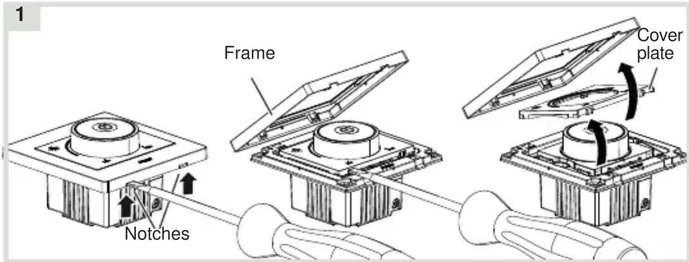
- Carefully loosen the frame on the notches with a flat-blade screwdriver (1).
■ Remove the cover plate.
Connecting the device
2A 2B


- Strip connection cables approx. 11 mm.
■ Wire the dimmer according to the connection diagram (2A). Can be installed alternatively with a change-over switch (2B).
Installing the device into the wall box
3

natural_image
Technical diagram of a mechanical assembly with labeled components and directional arrows (no text or symbols)■ After wiring, fix the device with the two screws attached into the wall box (3).
Assembling the cover plate and frame
4
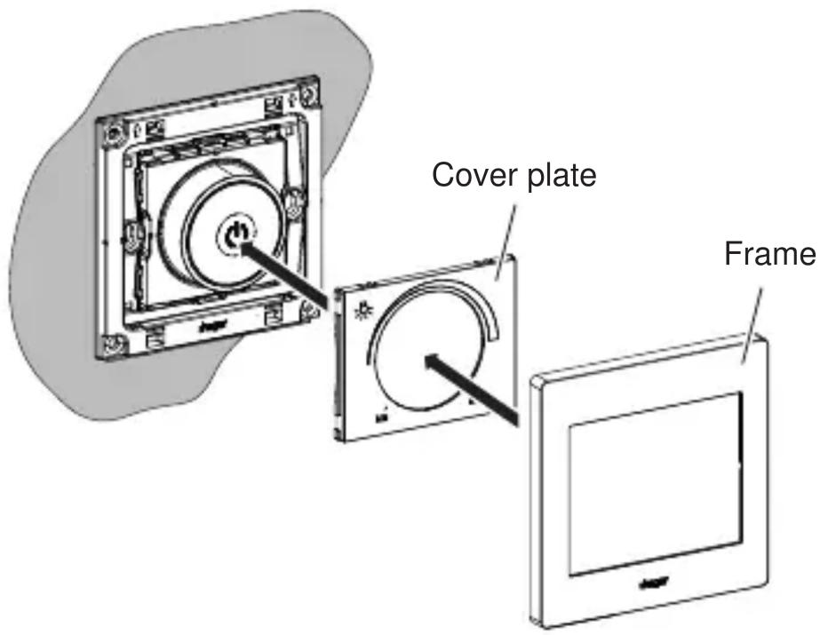
Place the cover plate in the correct position and fix with frame (4).

2-5gang frames are available for multiple combinations.





Brand : HAGER
Model : WGCXEDR500KB
Category : Light dimmer