
CU-NZ35YKE - Air conditioner PANASONIC - Free user manual and instructions
Find the device manual for free CU-NZ35YKE PANASONIC in PDF.


| Product Type | Split System Air Conditioner (Indoor + Outdoor) |
| Model Indoor Unit | CS-NZ35YKE |
| Model Outdoor Unit | CU-NZ35YKE |
| Brand | Panasonic |
| Power Supply | 220–240 V, 50 Hz, Single Phase |
| Cooling Capacity (Nominal) | 3.5 kW (approx.) |
| Heating Capacity (Nominal) | 4.0 kW (approx.) |
| Operation Modes | Auto, Cool, Heat, Dry, Fan Only |
| Air Purification | nanoeâ„¢X Generator (Biocidal) |
| Wireless Connectivity | Built-in Wireless LAN Module |
| Remote Control Range | Up to 8 m |
| Timer Functions | ON Timer, OFF Timer (up to 2 preset times) |
| Sleep Mode | Yes, with automatic temperature adjustment |
| Powerful Mode | Quick Cooling/Heating |
| Auto Restart | After Power Failure |
| Operating Temperature (Cooling) | Indoor: 16°C–32°C DB, Outdoor: -15°C–43°C DB |
| Operating Temperature (Heating) | Indoor: 16°C–30°C DB, Outdoor: -25°C–24°C DB |
| Air Filter | Washable, clean every 2 weeks |
| Maintenance Heating | Maintains room at 8°C or 15°C |
| Defrost Operation | Automatic in Heat mode |
| Error Code Retrieval | Via remote control when TIMER blinks |
Frequently Asked Questions - CU-NZ35YKE PANASONIC
User questions about CU-NZ35YKE PANASONIC
0 question about this device. Answer the ones you know or ask your own.
Ask a new question about this device
Download the instructions for your Air conditioner in PDF format for free! Find your manual CU-NZ35YKE - PANASONIC and take your electronic device back in hand. On this page are published all the documents necessary for the use of your device. CU-NZ35YKE by PANASONIC.
USER MANUAL CU-NZ35YKE PANASONIC
Operating Instructions
Air Conditioner
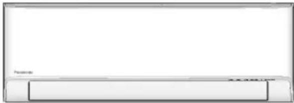
Model No.
Indoor Unit Outdoor Unit
CS-NZ25YKE
CU-NZ25YKE
CS-NZ35YKE
CU-NZ35YKE
CS-NZ50YKE
CU-NZ50YKE
Operating Instructions
2-10
Air Conditioner
Before operating the unit, please read these operating instructions thoroughly and keep them for future reference.
Before installation, the installer should:
Read the Installation Instructions, then request the customer keep them for future reference.
Remove the remote control packed with the indoor unit.
Bruksanvisning
12-20
Luftkonditionering
A new built-in Network Adaptor that allows you to control your heatpump from anywhere.
Use the remote control within 8 m from the remote control receiver on the indoor unit.
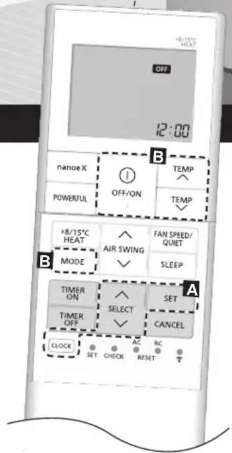
Quick Guide
Inserting the batteries
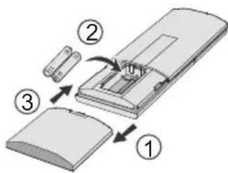
① Pull out the back cover of remote control.
② Insert AAA or R03 batteries.
③ Close the cover.
A Clock setting
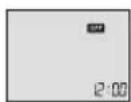
① Press CLOCK, then press to set the time.
- Press CLOCK for approximately 5 seconds to show the time as 12-hour (am/pm) or 24-hour.
② Press to confirm.
natural_image
Interior view of a minimalist living room with a sofa and high ceiling (no text or symbols)Thank you for purchasing Panasonic Air Conditioner.
Table of Contents
How to Use 4-5
To Learn More 6
Cleaning the
Air Conditioner 7
Troubleshooting 8-10
Accessories
- Remote control
• AAA or R03 batteries × 2 - Remote control holder
- Screws for remote control holder × 2
The illustrations in this manual are for explanation purposes only and may differ from the actual unit. They are subject to change without notice.
B Basic operation
start/stop the operation.
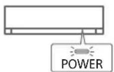
- When the unit is ON, OFF disappears from the remote control display.
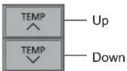
Selection range:
16.0 °C \~ 30.0 °C /
60^ 86^ .
- Press for approximately 10 seconds to show the temperature as °C or °F.
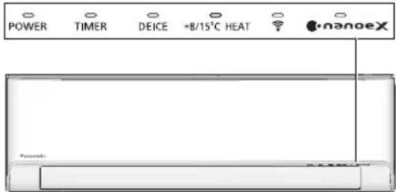
Indicators
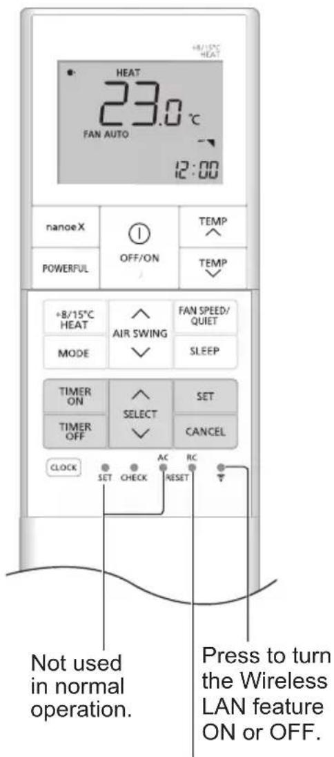
Press to restore the remote control to default setting.
To adjust airflow direction
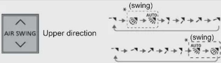
flowchart
graph TD
    A["AIR SWING"] --> B["Upper direction"]
    C["(swing)"] --> D["Auto"]
    E["(swing)"] --> F["Auto"]
Upper direction:
- Do not adjust the flap by hand.
* For details operation, refer "To Learn More...."
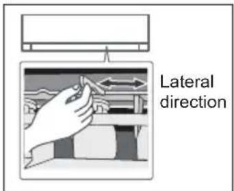
Lateral direction:
- For lateral direction, it is manually adjustable as shown.
To adjust FAN SPEED and QUIET condition

flowchart
graph LR
    A["FAN SPEED/QUIET"] --> B["FAN AUTO"]
    B --> C["QUIET"]
    C --> D["..."]
    D --> E["1000"]
    E --> F["10000"]
    F --> G["100000"]
FAN SPEED:
- When FAN AUTO is selected, the fan speed is adjusted automatically according to the operation mode.
- Select the lowest fan speed (■) to have a low noise operation.
QUIET:
• This operation reduces airflow noise.
To reach the desired temperature quickly

- This operation continues until it is cancelled by pressing again POWERFUL button or turn OFF the unit to stop this operation.
To use maintenance heating
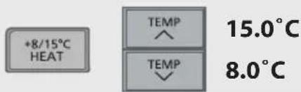
- Maintain indoor temperature at 8.0/15.0°C. Fan switches to high fan speed automatically.
- This operation overwrite the operation mode and could be cancelled by pressing MODE.
- Defrost operation at outdoor unit will result in sudden cold air from indoor unit. Eliminate cold air with heat mode.
To connect to a network

- For Wireless LAN Module operation setup, please refer to Setup Instructions Manual.
To maximise comfort while sleeping

- This operation provides you with a comfortable environment while sleeping. It will automatically adjust the sleep pattern temperature during the activation period.
- The indoor unit indicator will dim when this operation is activated. This is not applicable if the indicator brightness has been manually dimmed.
• This operation is incorporated with the activation timer (0.5, 1, 2, 3, 4, 5, 6, 7, 8 or 9 hours). - This operation can be set together with timer. Sleep operation has the priority over OFF timer.
- This operation can be cancelled by pressing the respective button until the sleep timer reaches 0.0h.
To enjoy fresher and cleaner environment

- This operation provides cleaner air, moisturises your skin and hair, and deodorises odours in the room.
- Press nanoe™X to activate this operation, either when the unit is ON or OFF. During nanoe™X individual operation, the fan speed will follow the remote control setting.
- If nanoe™X is activated before the unit is turned off, the nanoe™X operation will resume when the unit is turned on. This includes when TIMER ON is set.
- Press the button again to cancel.
To set the timer
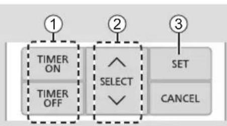
You can set the timer to turn on and off the unit at 2 different preset time.
flowchart
graph TD
    A["TIMER ON"] --> B["TIMER OFF"]
    B --> C["SELECT"]
    C --> D["SET"]
    C --> E["CANCEL"]
① Select TIMER ON or TIMER OFF.
• Each time pressed:
Example: OFF at 22:00

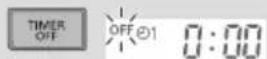
② Set the time.
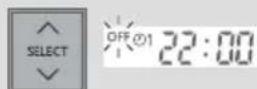
③Confi rm the setting.

- To cancel the timer, press TIME or to select the respective setting 01 or 02 then press CANCEL.
- If the timer has been cancelled manually or due to power failure, you can restore the timer again. Press TMEL ON or to select the respective setting ⏻1 or ⏻2 then press SET.
- The nearest timer setting is displayed and will activate in sequence.
- The timer operation follows the clock setting on the remote control and will repeat daily when timer has been set. For clock setting, refer to Quick Guide.
Note
- Can be selected at the same time.
- Can be activated in all modes.
- Cannot be selected at the same time.
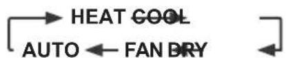
Operation mode
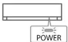
HEAT : The POWER indicator blinks at the initial stage. The unit will take some time to warm up. - If the HEAT mode system has been locked, and other operation mode is selected, the indoor unit stops and the POWER indicator blinks. - Unit may stops warm air supply for deice. The deice indicator ON during this operation.
COOL : Provides efficient comfort cooling to suit your needs.
DRY : Operates at low fan speed for a gentle cooling operation.
FAN : To circulate air in the room.
AUTO : The POWER indicator blinks at the initial stage.
The unit will select an operation mode every 10 minutes depending on the setting and room temperature.
Energy saving temperature setting
You may save energy when operating the unit within the recommended temperature range.
HEAT : 20.0 °C \~ 24.0 °C / 68 °F \~ 75 °F.
COOL : 26.0 °C \~ 28.0 °C / 79 °F \~ 82 °F.
Air flow direction
AUTO In COOL/DRY mode:

The horizontal fl ap swings up/down automatically.
Once the temperature is achieved, the horizontal flap is fixed at upper position.
In HEAT mode:
The horizontal flap fixed at the predetermined position.

In COOL/DRY mode:
The horizontal fl ap swings up/down automatically.
In HEAT mode:
The horizontal flap is fixed to upper position when discharge air temperature is cold.
The horizontal flap swings up-down automatically when discharge air temperature is warm.
Auto restart control
When power is resumed after a power failure, the operation will restart automatically with the last operation mode and airflow direction.
- This control is not applicable when TIMER is set.
Operating conditions
Use this air conditioner in the temperature range indicated in the table.
| Temperature °C (°F) | Indoor Outdoor | ||||
| DBT WBT DBT WBT | |||||
| COOL | Max. | 32 (89.6) | 23 (73.4) | 43 (109.4) | 26 (78.8) |
| Min. | 16 (60.8) | 11 (51.8) | -15 (5.0) | 11 (51.8) | |
| HEAT | Max. 30 (86.0) | - | 24 (75.2) | 18 (64.4) | |
| Min. | 16 (60.8) | - | -25 (-13.0) | - | |
| +8/15°C | Max. | 15 (59.0) | - | - | - |
| HEAT | Min. | 8 (46.4) | - | -25 (-13.0) | - |
DBT : Dry bulb temperature, WBT : Wet bulb temperature
Cleaning the Air Conditioner
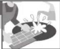
Cleaning has to be carried out at regular intervals to ensure the unit is at optimal performance. A dirty unit may cause malfunction and you may retrieve "H 99" error code. Consult an authorised dealer.
- Before cleaning, switch off the power supply and unplug the unit.
- Do not touch the aluminium fi n as the sharp parts may cause injury.
- Do not use benzine, thinner or scouring powder.
- Use soap ( pH 7) or neutral household detergent only.
- Do not use water hotter than 40^ / 104^ .
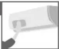
Indoor unit
Wipe the unit gently with a soft and dry cloth.
The coils and fans should be cleaned periodically by an authorised dealer.
Outdoor unit
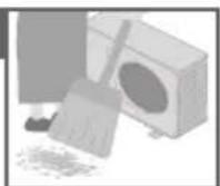
Clean the debris that surround the unit.
Clear any blockage from the drain pipe.
Front panel
Wash gently and dry.
How to remove front panel
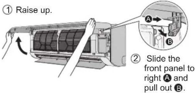
Close it securely
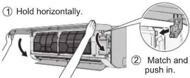
③ Close down.
④ Press both ends and center of the front panel.
Indoor unit
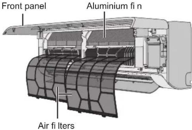
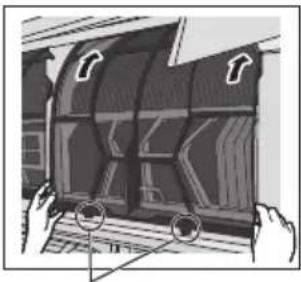
Air fi Iters
Once every 2 weeks
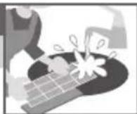
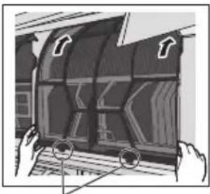
- Wash/rinse the fi Iters gently with water to avoid damaging the surface.
- Dry the filters thoroughly under a shade, away from fire or direct sunlight.
- Replace any damaged filters.
Remove air filter
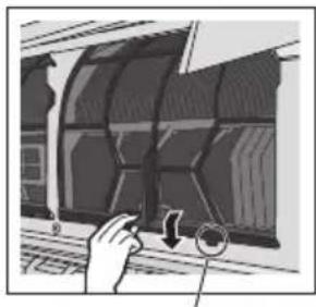
natural_image
Illustration of a hand interacting with a curved panel or panel, showing a circular arrow and a magnified inset (no text or symbols)Attach air filter
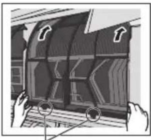
natural_image
Illustration of hands holding a curved object with arrows indicating direction (no text or symbols)Remove from the unit Insert into the unit
Troubleshooting
The following symptoms do not indicate malfunction.
| Symptom Cause | |
| POWER indicator blinks before the unit is switched on. | This is the preliminary step to prepare for the TIMER operation after it has been set.When Timer is set ON, the unit may start earlier (up to 35 minutes) before the actual set time to achieve the desired temperature on time. |
| POWER indicator blinks during HEAT mode with no warm air supply (and fl ap is closed). | The unit is in defrost mode (and AIR SWING has been set to AUTO). |
| POWER indicator blinks, then stops blinking during COOL/DRY mode. | The system has been locked to operate in HEAT mode only. |
| TIMER indicator is always ON. | When Timer has been set, the Timer setting repeats daily. |
| Operation is delayed a few minutes after restarting. | The delay is a protection to the unit's compressor. |
| Cooling/heating capacity is reduced during lowest fan speed setting. | The lowest fan speed is to have a low noise operation, so cooling/heating capacity may be reduced depending on the condition.Increase the fan speed to increase the capacity. |
| In COOL mode, when the room temperature reaches near the set temperature, the compressor stops, then the indoor unit fan speed reduced. | To prevent the room humidity rising. The indoor fan will resume running according to the set fan speed when room temperature increase. |
| Indoor fan stops occasionally during heating operation. | To avoid unintended cooling effect. |
| Indoor fan stops occasionally during automatic fan speed setting. | This is to help remove the surrounding odour. |
| Airflow continues even after operation has stopped. | To extract the remaining heat from the indoor unit (maximum 30 seconds). |
| During deice operation, fl ap is closed. | The AIR SWING is set to AUTO. |
| The room has a peculiar odour. | This may be due to damp smell emitted by the wall, carpet, furniture or clothing. |
| Cracking sound during operation. | Changes in temperature caused the unit to expand and contract. |
| Water flowing sound during operation. | Refrigerant flow inside the unit. |
| Mist emerges from indoor unit. | During cooling operation, the discharged cold air may condense to water vapour. |
| Outdoor unit emits water or steam. | During cooling operation, condensation occurs on cold pipes and the condensed water may drip from the outdoor unit.During heating operation, frost formed on the outdoor unit during deice cycle melts and is discharged as water or steam. |
| Discoloration of some plastic parts. | Discoloration is subjected to the types of materials used in plastic parts. It is accelerated when exposed to heat, sun light, UV light or environmental factors. |
| Soft buzzing sound from indoor unit during nanoeTMX operation. | It is normal when the nanoeTMX generator is working. If you are concerned about the sound, cancel the nanoeTMX operation. |
| Wireless LAN indicator is ON when the unit is OFF. | The unit's wireless LAN connection with the router has been activated. |
Check the following before calling for servicing.
| Symptom Check | |
| Operation in HEAT/COOL mode is not working effi ciently. | Set the temperature correctly.Close all doors and windows.Clean or replace the fi Iters.Clear any obstruction at the air inlet and air outlet vents. |
| Noisy during operation. | Check if the unit has been installed at an incline.Close the front panel properly. |
| Remote control does not work.(Display is dim or transmission signal is weak.) | Insert the batteries correctly.Replace weak batteries. |
| The unit does not work. | • Check if the circuit breaker is tripped.• Check if timers have been set. |
| The unit does not receive the signal from the remote control. | • Make sure the receiver is not obstructed.• Certain fl fluorescent lights may interfere with the signal transmitter. Consult an authorised dealer. |
| The nanoeTMX indicator at the indoor unit is not ON when nanoeTMX is activated. | • Use the remote control to retrieve the error code and consult an authorised dealer. |
When...
■ The remote control is missing or a malfunction has occurred
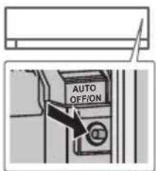
- Raise the front panel.
- Press AUTO OFF/ON once to use in AUTO mode.
- Press AUTO OFF/ON hold for 5 seconds until you hear 1 beep, then release to use in forced COOL mode. (This operation shall be performed by service personnel)
- Press AUTO OFF/ON hold for 8 seconds until you hear 2 beep, then release to use in forced HEAT mode. (This operation shall be performed by service personnel)
- Press AUTO OFF/ON again to turn off the unit.
■ The indicators are too bright
- To dim or restore the indicators' brightness on the unit, press on the remote for 5 seconds.
■ Conducting a seasonal inspection after extended period of non-use
- Check the batteries.
- Check that there is no obstruction around the air inlets and outlet vents.
- Use AUTO OFF/ON on the unit to select COOL or HEAT mode. For details, refer "The remote control is missing or a malfunction has occurred" above. After 15 minutes of operation, it is normal to have the following temperature difference between the air inlet and outlet vents:
COOL: ≥ 8 °C / 14.4 °F HEAT: ≥ 14 °C / 25.2 °F
■ The units will be not used for an extended period
- Activate HEAT mode for 2\~3 hours to remove any moisture left in the internal parts thoroughly. This is to prevent mould growth.
- Turn off the power supply and unplug the unit.
- Remove the batteries from the remote control.
NON SERVICEABLE CRITERIAS
TURN OFF THE POWER SUPPLY AND UNPLUG THE UNIT. Then consult an authorised dealer in the following conditions:
• Abnormal noise during operation.
• Water/foreign particles have entered the remote control.
• Water is leaking from the indoor unit.
- The circuit breaker switches off frequently.
• The power cord becomes unnaturally warm.
- The switches or buttons are not functioning properly.
How to retrieve error codes
If the unit stops and the TIMER indicator blinks, use the remote control to retrieve the error code.
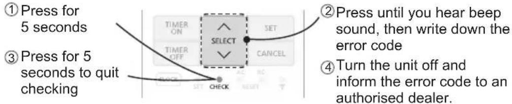
- For certain errors, you may restart the unit for limited operation if there are 4 beeps when operation starts.
| Diagnostic display | Abnormality/Protection control |
| H 00 No memory of failure | |
| H 11 | Indoor/outdoor abnormal communication |
| H 12 Indoor unit capacity unmatched | |
| H 14 | Indoor intake air temperature sensor abnormality |
| H 15 | Outdoor compressor temperature sensor abnormality |
| H 16 | Outdoor current transformer (CT) abnormality |
| H 17 | Outdoor suction temperature sensor abnormality |
| H 19 Indoor fan motor mechanism lock | |
| H 21 | Indoor fl oat switch operation abnormality |
| H 23 | Indoor heat exchanger temperature sensor 1 abnormality |
| H 24 | Indoor heat exchanger temperature sensor 2 abnormality |
| H 25 | Indoor ion device abnormality |
| H 26 Minus ION abnormality | |
| H 27 | Outdoor air temperature sensor abnormality |
| H 28 | Outdoor heat exchanger temperature sensor 1 abnormality |
| H 30 | Outdoor discharge pipe temperature sensor abnormality |
| H 31 Abnormal swimming pool sensor | |
| H 32 | Outdoor heat exchanger temperature sensor 2 abnormality |
| H 33 | Indoor/outdoor misconnection abnormality |
| H 34 | Outdoor heat sink temperature sensor abnormality |
| H 35 | Indoor/outdoor water adverse current abnormality |
| H 36 | Outdoor gas pipe temperature sensor abnormality |
| H 37 | Outdoor liquid pipe temperature sensor abnormality |
| H 38 Indoor/outdoor mismatch (brand code) | |
| H 39 | Abnormal indoor operating unit or standby units |
| Diagnostic display | Abnormality/Protection control |
| H 41 | Abnormal wiring or piping connection |
| H 50 Ventilation fan motor locked | |
| H 51 Ventilation fan motor locked | |
| H 52 | Left-right limit switch fi xing abnormality |
| H 58 Indoor gas sensor abnormality | |
| H 59 Eco sensor abnormality | |
| H 64 | Outdoor high pressure sensor abnormality |
| H 67 nanoe abnormality | |
| H 70 Light sensor abnormality | |
| H 71 | DC cooling fan inside control board abnormality |
| H 72 Abnormality tank temperature sensor | |
| H 85 | Abnormal communication between indoor & wireless LAN module |
| H 97 Outdoor fan motor mechanism lock | |
| H 98 Indoor high pressure protection | |
| H 99 Indoor operating unit freeze protection | |
| F 11 4-way valve switching abnormality | |
| F 16 Total running current protection | |
| F 17 | Indoor standby units freezing abnormality |
| F 18 Dry circuit blocked abnormality | |
| F 87 Control box overheat protection | |
| F 90 | Power factor correction (PFC) circuit protection |
| F 91 Refrigeration cycle abnormality | |
| F 93 | Outdoor compressor abnormal revolution |
| F 94 | Compressor discharge pressure overshoot protection |
| F 95 | Outdoor cooling high pressure protection |
| F 96 | Power transistor module overheating protection |
| F 97 Compressor overheating protection | |
| F 98 Total running current protection | |
| F 99 | Outdoor direct current (DC) peak detection |
natural_image
Interior view of a minimalist living room with a sofa and high ceiling (no text or symbols)KYLA: 26,0 °C \~ 28,0 °C / 79 °F \~ 82 °F.
Luftfl ödesriktning

I läget KYLA/DRY:
natural_image
Illustration of a hand interacting with a car window, showing a circular button and arrow (no text or symbols)natural_image
Illustration of hands holding a computer with a stylized open book (no text or symbols visible)natural_image
Interior view of a minimalist living room with a sofa and high ceiling (no text or symbols)KJ∅LIG: 26,0 °C \~ 28,0 °C / 79 °F \~ 82 °F.
Luftstrømretning
AUTO Når du velger KJ∅LIG/T∅RR-modus:

Luftfi Iter
En gang annenhver uke
natural_image
Illustration of a hand adjusting a mechanical component with a circular arrow indicating rotation (no text or symbols present)Fest luftfilter
natural_image
Illustration of a person opening a curved window with arrows indicating direction (no text or symbols)16,0 °C \~ 30,0 °C /
60^ 86^ .
natural_image
Illustration of a hand interacting with a window-like object, possibly a device or architectural component (no visible text or symbols)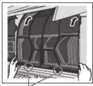
natural_image
Illustration of hands holding a curved object with arrows pointing to it, no visible text or symbolsnatural_image
Interior view of a minimalist living room with a sofa and wooden flooring (no text or symbols)starte/stoppe driften.
AFK∅LING : 26,0 °C \~ 28,0 °C / 79 °F \~ 82 °F.
Indendørs enhed
natural_image
Illustration of a hand adjusting a panel with a magnified inset showing a circular detail (no text or symbols)Montér luftfilter
natural_image
Illustration of a hand holding a curved object with directional arrows, no visible text or symbolsThis air conditioner incorporates a device that generates a biocidal product.
Free radicals generated by a device incorporated in the air conditioner have the capacity to inhibit pollutants, such as certain types of bacteria, viruses, mould.
Active substances : Free radicals generated in situ from ambient air or water.
Usage : This device function can be operated ON / OFF by "nanoe X" icon button. Do refer to "How to Use" for more details.
Svenska

- Operating Instructions
- Air Conditioner
- Quick Guide
- Table of Contents
- Accessories
- B Basic operation
- Upper direction:
- Lateral direction:
- FAN SPEED:
- QUIET:
- To maximise comfort while sleeping
- To enjoy fresher and cleaner environment
- To set the timer
- ① Select TIMER ON or TIMER OFF.
- ② Set the time.
- ③Confi rm the setting.
- Note
- Operation mode
- Energy saving temperature setting
- Air flow direction
- AUTO In COOL/DRY mode:
- Auto restart control
- Operating conditions
- Cleaning the Air Conditioner
- Indoor unit
- Outdoor unit
- Front panel
- How to remove front panel
- Close it securely
- Air fi Iters
- Troubleshooting
- When...
- ■ The remote control is missing or a malfunction has occurred
- ■ The indicators are too bright
- ■ Conducting a seasonal inspection after extended period of non-use
- ■ The units will be not used for an extended period
- NON SERVICEABLE CRITERIAS
- How to retrieve error codes
- Luftfl ödesriktning
- I läget KYLA/DRY:
- Luftstrømretning
- Luftfi Iter
- Indendørs enhed
- Svenska
Brand : PANASONIC
Model : CU-NZ35YKE
Category : Air conditioner