Illustra Essentials IES02D1OCWIYB - Surveillance Camera Tyco - Free user manual and instructions
Find the device manual for free Illustra Essentials IES02D1OCWIYB Tyco in PDF.


| Product Type | Surveillance Camera |
| Brand | Tyco |
| Model | Illustra Essentials IES02D1OCWIYB |
| Image Sensor | 2 MP Progressive Scan CMOS |
| Resolution | 1920 x 1080 at 30 fps |
| Lens | 2.8 mm fixed lens with 110° viewing angle |
| Night Vision | Up to 30 meters (98 ft) with IR LEDs |
| Dimensions (W x H x D) | 72 mm x 180 mm x 70 mm (2.83 in x 7.09 in x 2.76 in) |
| Weight | 0.6 kg (1.32 lb) |
| Power Supply | PoE (IEEE 802.3af) or 12 VDC |
| Power Consumption | 6.5 W (max) |
| Network Interface | 10/100 Base-T Ethernet |
| Video Compression | H.265, H.264, MJPEG |
| Audio | Built-in microphone (audio recording) |
| Main Features | Motion detection, tamper alarm, privacy mask, ONVIF compliant |
| Ingress Protection | IP66 (weather-resistant for outdoor use) |
| Operating Temperature | -30°C to 60°C (-22°F to 140°F) |
| Storage | MicroSD card slot (up to 256 GB) or NAS/cloud |
| Mounting | Wall or ceiling mount with included bracket |
| Regulatory Approvals | FCC, CE, RoHS |
| Maintenance | Clean the lens with a soft, dry cloth. Do not use abrasive cleaners. |
| Warranty | 3-year limited warranty |
Frequently Asked Questions - Illustra Essentials IES02D1OCWIYB Tyco
User questions about Illustra Essentials IES02D1OCWIYB Tyco
0 question about this device. Answer the ones you know or ask your own.
Ask a new question about this device
Download the instructions for your Surveillance Camera in PDF format for free! Find your manual Illustra Essentials IES02D1OCWIYB - Tyco and take your electronic device back in hand. On this page are published all the documents necessary for the use of your device. Illustra Essentials IES02D1OCWIYB by Tyco.
USER MANUAL Illustra Essentials IES02D1OCWIYB Tyco
Illustra Essentials Network Camera Web3.0 User Manual
Notice
Please read this manual thoroughly and save it for future use before attempting to connect or operate this unit.
The information in this manual was current when published. The manufacturer reserves the right to revise and improve its products. All specifications are therefore subject to change without notice.
Copyright
Under copyright laws, the contents of this manual may not be copied, photocopied, reproduced, translated or reduced to any electronic medium or machine-readable form, in whole or in part, without prior written consent of Tyco Security Products. © 2014 Tyco Security Products. All rights reserved.
Customer Service
Thank you for using Tyco Security Products. We support our products through an extensive worldwide network of dealers. The dealer through whom you originally purchased this product is your point of contact if you need service or support. Our dealers are empowered to provide the very best in customer service and support. Dealers should contact Tyco Security Products at (800) 507-6268 or (561) 912-6259 or on the Web at www.illustraeessentials.com.
Trademarks
The trademarks, logos, and service marks displayed on this document are registered in the United States [or other countries]. Any misuse of the trademarks is strictly prohibited and Tyco Security Products. will aggressively enforce its intellectual property rights to the fullest extent of the law, including pursuit of criminal prosecution wherever necessary. All trademarks not owned by Tyco Security Products. are the property of their respective owners, and are used with permission or allowed under applicable laws.
Product offerings and specifications are subject to change without notice. Actual products may vary from photos. Not all products include all features. Availability varies by region; contact your sales representative.
Table of Contents
Network Connection....1
Main Interface Introduction 2
Log in....2
Live Interface 6
Encode Setup....7
System Menu....7
Video Window Function Option....7
Video Window Setup 8
Hide Image Control....8
Original size 9
Full screen 9
Width and height ratio....9
Fluency Adjustment 9
Image control 9
Setup....11
Camera....11
Conditions....11
Video 17
Network....22
TCP/IP....22
Connection 24
PPPoE....25
DDNS....26
IP filter 27
SMTP (e-mail)....28
UPnP 29
SNMP 30
Bonjour....32
Multicast....33
802.1x 34
QoS 35
Event....36
Video detect 36
Abnormity 41
Storage 43
Record Schedule and Snapshot Schedule 43
Destination 44
Record control....45
System....46
General 46
Account 48
Default....52
Import/Export....52
Auto Maintenance ....53
Upgrade ....53
Information....54
Version 54
Log 54
Online User 55
Alarm 56
Log out ....57
These series of network camera products support the Web access and management via PC.
Web includes several modules: monitor channel preview, PTZ control, system configuration, alarm and etc.
Please follow the steps listed below for network connection.
Make sure the network camera has connected to the network properly.
Network camera IP address and PC IP address shall be in the same network segment. If there is router, please set the corresponding gateway and subnet mask.
Use order ping ***.***.***.***(* network camera address) to check connection is OK or not.
Log in
Open IE and input network camera address in the address bar.
For example, if your camera IP is 192.168.1.108, then please input http://192.168.1.108 in IE address bar. See Figure 2-1.
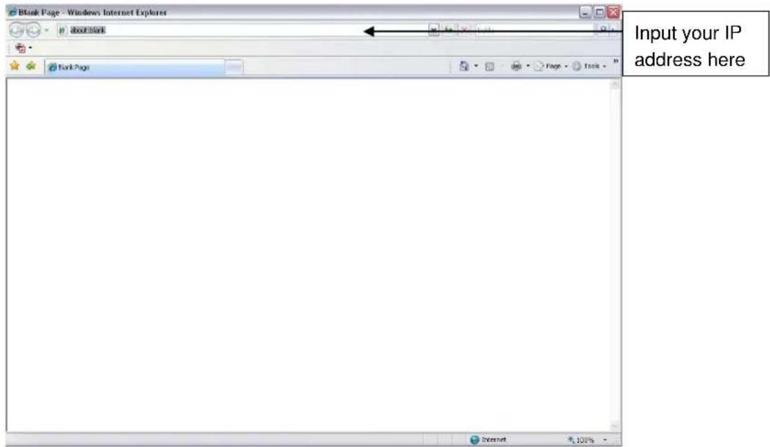
Figure 2-1
The login interface is shown as below. See Figure 2-2.
Please input your user name and password.
Default factory name is admin and password is admin.
Note
For security reasons, please modify your password after you first login.

Figure 2-2
If it is your first time to login in, you may see the interface shown as in Figure 2-3.

Figure 2-3
Click on "Please click here to download and install the plug-in". The system pops up warning information to ask you whether run or save this plug-in. See Figure 2-4.

Figure 2-4
You must either run or save the file to local and install it. Follow the following steps. Click on run, you will see Figure 2-5 and Figure 2-6.

Figure 2-5

Figure 2-6
When plug-in installation completes, the installation page closes automatically. The web-end will refresh automatically, and then you can view video captured by the camera.
Live Interface
After you logged in, you can see the live monitor window. See Figure 2-7
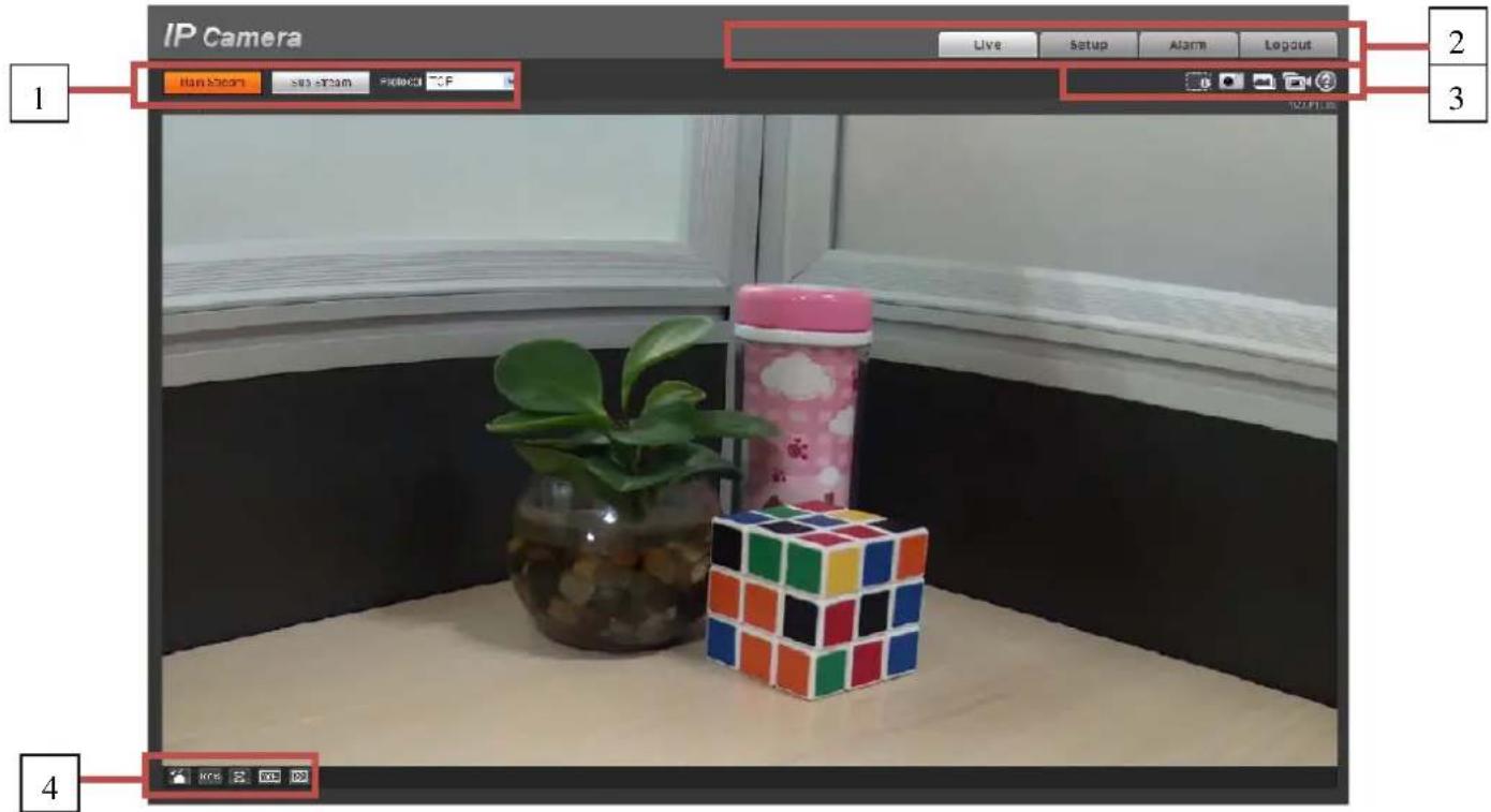
Figure 2-7
There are four sections:
• Section 1: Encode setup bar
• Section 2: System menu
• Section 3: Window function option bar
• Section 4: Window adjust bar
Encode Setup
The encode setup interface is shown as in Figure 2-8.

Figure 2-8
Please refer to the following sheet for detailed information.
| Parameter Function | |
| Main stream | In normal network width environment, main stream can record audio/video file and realize network monitor.You can set the main stream resolution if your device supports. |
| Sub (Extra) stream | If network width is not sufficient, you can use sub stream to realize network monitor. |
| Protocol | You can select stream media protocol from the dropdown list.There are three options: TCP/UDP/Multicast |
System Menu
System menu is shown as in Figure 2-9.
Please refer to chapter 2.2 Live, chapter 3 Setup, chapter 4 Alarm, chapter 5 Log out for detailed information.

Figure2-9
Video Window Function Option
The interface is shown as below. See Figure 2-10

Figure 2-10
Please refer to the following sheet for detailed information.
| SN Parameter Function | ||
| 1 Digital zoom | ● When the video is in the original status, click it you can select any zone to zoom in. In the non-original status, you can drag the zoom-in zone in specified range. Right click mouse to restore previous status. ● Click it; you can use the middle button of the mouse to zoom in/out the video size. | |
| 2 Snapshot | You can snapshot important video by clicking on this button. All images are memorized in system folder: \ picture download (default). You can go to Setup->Camera->Video->Path to modify the local record save path. | |
| 3 Triple snap | Click it, system can snap at 1f/s. All images are memorized in system storage folder. | |
| 4 | Record | For manual record. All records are memorized in Setup->Camera->Video->Path. |
| 5 | Help | Click it to open help file. |
Video Window Setup
The interface is shown as in Figure 2-11.

Figure 2-11
Hide Image Control
Click this button to display/hide image control interface.
Original size
Click this button to go to original size. It is to display the actual size of the video stream. It depends on the resolution of the bit stream.
Full screen
Click it to go to full-screen mode. Double click the mouse or click the Esc button to exit the full screen.
Width and height ratio
Click it to restore original ratio or suitable window.
Fluency Adjustment
There are three levels of fluency for you to select. The default is real-time with minimum delay. You may select fluent mode in case connection is slow.
Image control
Click it to open picture setup interface. See Figure 2-12. This interface is on the top right pane.

Figure 2-12
Please refer to the following sheet for detailed information.
| Parameter Function | |||
| Video setup | [3HXX] | It is to adjust monitor video brightness. | Note:● All the operations here apply to WEB end only.● Please go to Setup->Camera->Conditions to adjust corresponding items. |
| [05HA] | It is to adjust monitor video contrastness. | ||
| [XOKO] | It is to adjust monitor video hue. | ||
 | It is to adjust monitor video saturation. | ||
| Reset | Restore brightness, contrastness saturation and hue to system default setup. | ||
Camera
Conditions
Here you can view device property information. Slight differences may be found due to different network camera series. The setups become valid immediately after you set. See Figure 3-1.
Note:
Only motorized zoom lens device has zoom and focus function.
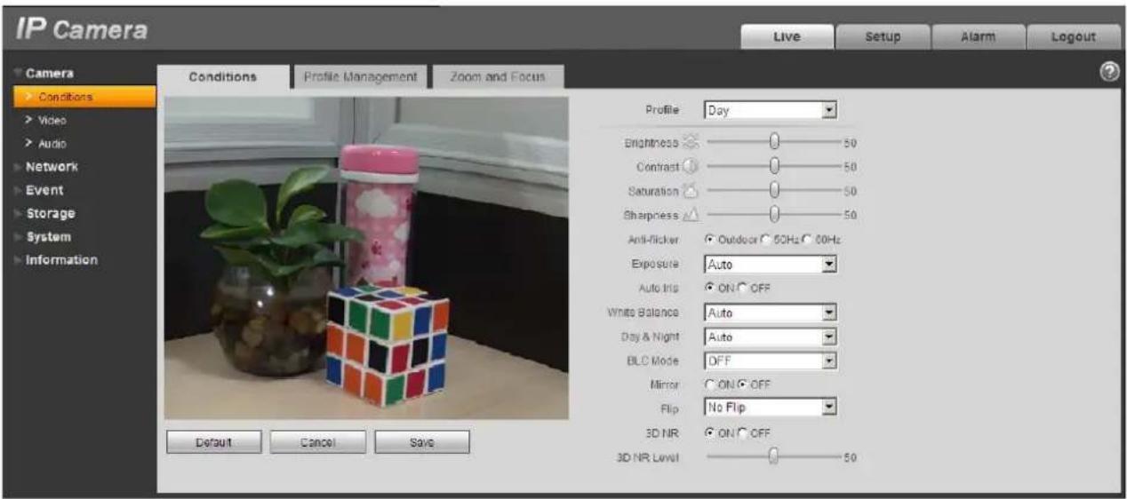
Figure 3-1
Please refer to the following sheet for detailed information.
| Parameter Function | ||
| Profile | You may select normal, day and night mode. | |
| Brightness | It is to adjust monitor window brightness. You can adjust this value if the video is too dark or too bright. The larger the number, the bright the video is. When you input the value here, the bright section and the dark section of the video will be adjusted accordingly. Please note the video may become hazy if the value is too high.The value ranges from 0 to 100. The recommended value ranges from 40 to 60. The default value is 50. | |
| Contrast | It is to adjust monitor window contrast. The larger the number, the higher the contrast is. You can use this function when the whole video bright is OK but the contrast is not proper. Please note the video may become hazy if the value is too low. If this value is too high, the dark section may lack brightness while the bright section may over exposure.The value ranges from 0 to 100. The recommended value ranges from 40 to 60. The default value is 50. | |
| Saturation | It is to adjust monitor window saturation. The larger the number, the strong the color is. This value has no effect on the general brightness of the whole video. The video color may become too strong if the value is too high. For the grey part of the video, the distortion may occur if the white balance is not accurate. Please note the video may not be attractive if the value is too low.The value ranges from 0 to 100. The recommended value ranges from 40 to 60.The default value is 50. | |
| Sharpness | The value here is to adjust the edge of the video. The larger the value is, the clear the edge is and vice versa. Please note there is noise if the value here is too high.The value ranges from 0 to 100. The recommended value ranges from 40 to 60.The default value is 50. | |
| Anti-flicker | Outdoor: In this mode, you can switch exposure mode to get the effect under the corresponding exposure mode.50Hz: When the current is 50Hz, system can auto adjust the exposure according to the environment brightness in case there is any strip.60Hz: When the current is 60Hz, system can auto adjust the exposure according to the environment brightness in case there is any strip. | |
| Exposure | Auto The videoLow noise ● | whole brightness can automatically change within the proper exposure range according to the different environments. The higher the gain max value is, the lower the noise is.The video whole brightness can automatically change within the proper exposure range according to the different environments. The higher the gain max value is, the lower the noise is.● For the same environments, the noise of the low noise mode shall be smaller than the noise of the auto mode. |
| Low motion blur | ● The video whole brightness can automatically change within the proper exposure range according to the different environments. The lower the exposure max value is, the week the tail is.● For the same environments, the noise of the low motion blur mode shall be smaller than that of the auto mode. | |
| Manual | It is to display manual exposure value. | |
| Auto Iris | Before the setup, please make sure you have installed the auto iris. You can check the box before ON to enable this function. The auto iris may change if the light becomes different.When you disable this function, the iris is at the max. System does not add the auto iris function in the exposure control.This function is on by default. | |
| White Balance | It is to set the white balance mode. It has effect on the general hue of the video. This function is on by default.You can select the different scene mode such as auto, sunny, cloudy, home, office, night, disable and etc to adjust the video to the best quality.● Auto: The auto white balance is on. System can auto compensate the color temperature to make sure the vide color is proper.● Sunny: The threshold of the white balance is in the sunny mode.● Night: The threshold of the white balance is in the night mode.● Customized: You can set the gain of the red/blue channel. The value reneges from 0 to 100.● Outdoor: White balance threshold sets to outdoor mode. | |
| Day&Night | It is to set device day/night mode switch independently from config file. Default is auto mode.● Color: Device outputs the color video.● Auto: Device auto select to output the color or the B/W video according to the device feature (The general bright of the video or there is IR light or not.)● B/W: The device outputs the black and white video.● Sensor input: It is for external connection to IR light to control day/night mode.Note: Only some non-IR devices support sensor input function. | |
| BLC Mode | BLC | The device auto exposures according to the environments situation so that the darkest area of the video is cleared |
| WDR For the | WDR scene, this function can lower the high bright section and enhance the brightness of the low bright section. So that you can view these two sections clearly at the same time.The value ranges from 1 to 100. When you switch the camera from no-WDR mode to the WDR mode, system may lose several seconds record video. | |
| HLC After you | enabled HLC function, the device can lower the brightness of the brightest section according to the HLC control level. It can reduce the area of the halo and lower the brightness of the whole video.The value ranges from 0 to 100. The default value is 50 when HLC is on.HLC is enabled only when anti-flicker is outdoor and exposure mode is auto. | |
| Off It is to disable the BLC function. Please note this function is disabled by default. | ||
| Full-screen Test | Click the button on the video window, you can begin full-screen test. | |
| Flip | It is to switch video up and bottom limit.This function is disabled by default.The video resolution shall be 720P or below if you want to flip 90°. | |
| 3D NR | This threshold is mainly for multi-frame (at least 2) image processing. It reduces noise with info between a frame and previous frame. The higher the value, the better NR will be. Default is enabled. NR level ranges from 0 to 100. The recommended value to from 40 to 60. Default value is 50. | |
| Mirror | It is to switch video left and right limit.This function is disabled by default. | |
| Cancel | It is to cancel the operation in current interface and restore previously saved operation. | |
| Default | It is to set device default setup. | |
| OK | Save config. | |
Profile management has three modes: normal, full time and schedule. If you select normal, the video will be configured as normal as in Figure 3-2.

Figure 3-2
If you select full time, you must select either day or night, and the video will be configured accordingly as in Figure 3-3.
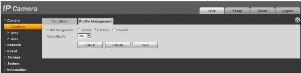
Figure 3-3
If you select schedule, you can decide detained day time interval and night time interval as in Figure 3-4. You can set 0:00 \~ 12:00 as day, and 12:00 \~ 24:00 as night.

Figure 3-4
Video
Video bit stream
The video bit stream interface is shown as below. See Figure 3-5.

Figure 3-5
Please refer to the following sheet for detailed information.
| Parameter Function | ||
| Main stream | Bit stream typeEncode mode | It includes general stream, motion stream and alarm stream. You can select different encode frame rates form different recorded events.System supports active control frame function (ACF). It allows you to record in different frame rates.For example, you can use high frame rate to record important events, record scheduled event in lower frame rate and it allows you to set different frame rates for motion detection record and alarm record.There are three options: H.264 (main profile standard), H.264H (high profile standard), H.264B (baseline standard)encode and MJPG encode.H.264: Main Profile encode mode.H.264H: High Profile encode mode.H.264B: Baseline Profile encode modeMJPEG: In this encode mode, the video needs larger bit stream to guarantee the video definition. You can use the max bit stream value in the recommend bit to get the better video output effect. |
| Resolution | There are multiple resolutions. You can select from the dropdown list.For each resolution, the recommended bit stream value is different.ImportantYou can not set a resolution higher than 720P (not including 720P) when the flip function is in process. | |
| Frame Rate | PAL: 1~25f/s, NTSC: 1~30f/s..The frame rate may vary due to different resolutions. | |
| Bit Rate Type | There are two options: VBR and CBR.Please note, you can set video quality in VBR mode. | |
| Reference Bit Stream | Reference bit rate value according to the resolution and frame rate you have set. | |
| Bit Rate | In VBR, the bit rate here is the max value. In CBR, it is a fixed value.See reference bit stream for recommended value. | |
| IFrame Here you can set the P frame amount between two I frames. The value ranges from 1 to 150. Default value is 50.Recommended value is frame rate *2. | ||
| Watermark | This function allows you to verify the video is tampered or not.Here you can select watermark bit stream, watermark mode and watermark character. Default character is DigitalCCTV.The max length is 85-digit. The character can only include number, character and underline. | |
| Substream | Enable | Please check the box here to enable extra stream function.This function is enabled by default. |
| Bit stream type | General bit stream. | |
| Encode mode | There are three options: H.264(main profile standard, H.264H (high profile standard), H.264B(baseline standard)encode and MJPG encode.The H.264, H.264H and H.264B both are H264 bit stream. H.264 is the Main Profile encode and the H.264B is the Baseline Profile encode mode. H.264B is for Blackberry cell phone to realize the monitor. You need to enable the sub stream function in your camera and set the resolution as CIF. Then you can monitor via the Blackberry cell phone.MJPEG: In this encode mode, the video needs to large bit stream to guarantee the video definition. You can use the max bit stream value in the recommend bit to get the better video output effect. | |
| Resolution | There are multiple resolutions. You can select from the dropdown list.For each resolution, the recommended bit stream value is different. | |
| Frame Rate | PAL: 1~25f/s, NTSC: 1~30f/s..The frame rate may vary due to different resolutions. | |
| Bit Rate Type | There are two options: VBR and CBR.Please note, you can set video quality in VBR mode. | |
| Recommended Bit | Recommended bit rate value according to the resolution and frame rate you have set. | |
| Bit Rate | In CBR, the bit rate here is the max value. In dynamic video, system needs to low frame rate or video quality to guarantee the value.The value is null in VBR mode.Please refer to recommend bit rate for the detailed information. | |
| I Frame Here you can set the P frame amount between two I frames. The value ranges from 1 to 150. Default value is 50.Recommended value is frame rate *2. | ||
Snapshot
The snapshot interface is shown as in Figure 3-.6

Figure 3-6
Please refer to the following sheet for detailed information.
| Parameter Function | |
| Snapshot type | There are two modes: general (schedule) and Event (activation). |
| Image size | It is the same with the resolution of snapshot (main stream or sub stream). |
| Quality | It is to set the image quality. There are six levels. |
| Snapshot bit stream | It is to set snapshot bit rate as main or sub. |
| Interval | It is to set snapshot frequency. The value ranges from 1s to 7s. |
Video Overlay
The video overlay interface is shown as in Figure 3-7.
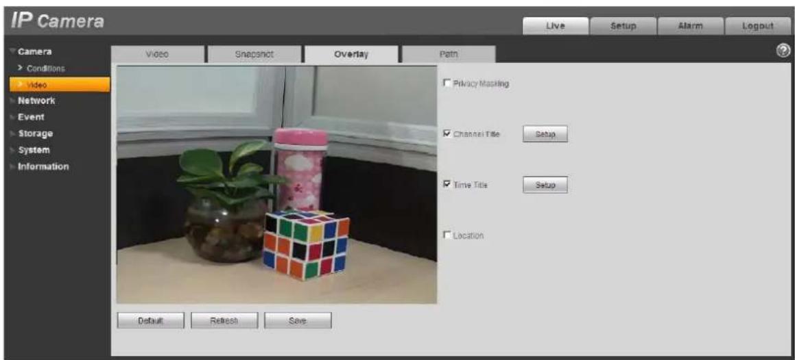
Figure 3-7
Please refer to the following sheet for detailed information.
| Parameter Function | |
| Privacy mask | ● Here you can privacy mask the specified video in the monitor video.● System max supports 4 privacy mask zones. |
| Time Title | ● You can enable this function so that system overlays time information in video window.● You can use the mouse to drag the time tile position. |
| Channel Title | ● You can enable this function so that system overlays channel information in video window.● You can use the mouse to drag the channel tile position. |
| Location | ● You can enable this function to overlay location information in video window.● You can click on setup button to set location information. You can use the mouse to drag location box to adjust its position. Alignment include align left and align right. |
Path
The storage path interface is shown as in Figure 3-8.
Here you can set snap image saved path (in the preview interface) and the record storage path (

(in the preview interface).The default setup is C:\PictureDownload and C:\RecordDownload.
Please click the Save button to save current setup.

Figure 3-8
Network
TCP/IP
The TCP/IP interface is shown as in Figure 3-9.

Figure 3-9
Please refer to the following sheet for detailed information.
| Parameter Function | |
| Host Name | It is to set current host device name. It max supports 32-digit character. |
| Ethernet Card | Please select the Ethernet port. It is for the wire LAN by default.Please note for the -W series product, it has the wireless network card, and you can modify the default Ethernet port setup.Please note the device needs to reboot to activate the new setup once you modify the default setup. |
| Mode | There are two modes: static mode and the DHCP mode.The IP/submask/gateway are null when you select the DHCP mode to auto search the IP.If you select the static mode, you need to set the IP/submask/gateway manually.If you select the DHCP mode, you can view the IP/submask/gateway from the DHCP.If you switch from the DHCP mode to the static mode, you need to reset the IP parameters.Besides, IP/submask/gateway and DHCP are read-only when the PPPoE dial is OK. |
| Mac Address | It is to display hose Mac address. |
| IP Version | It is to select IP version. IPV4 or IPV6.You can access the IP address of these two version. |
| IP Address | Please use the keyboard to input the corresponding number to modify the IP address and then set the corresponding subnet mask and the default gateway. |
| Preferred DNS DNS IP address. | |
| Alternate DNS Alternate DNS IP address. | |
| Enable ARP/Ping set device IP address service. | You can use ARP/Ping command to modify or set the device IP address if you know the device MAC address.Before the operation, please make sure the network camera and the PC in the same LAN. This function is on by default.You can refer to the steps listed below.Step 1: Get an IP address. Set the network camera and the PC in the same LAN.Step 2: Get the physical address from the label of the network camera.Step 3: Go to the Run interface and then input the following commands.arp -s <IP Address> <MAC>ping -l 480 -t <IP Address>Such as: arp -s 192.168.0.125 11-40-8c-18-10-11 ping -l 480 -t 192.168.0.125Step 4: Reboot the device.Step 5: You can see the setup is OK if you can see there are output information such as “Reply from 192.168.0.125 ...” from the command output lines. Now you can close the command line.Step 6: Open the browse and then input http://<IP addres>. Click the Enter button, you can access now. |
Connection
The connection interface is shown as in Figure 3-10.

Figure 3-10
Please refer to the following sheet for detailed information.
| Parameter Function | |
| Max connection | It is the max Web connection for the same device. The value ranges from 1 to 20. The max connection amount is 20. |
| TCP port The default value is 37777. You can input the actual port number if necessary. | |
| UDP port | The default value is 37778. You can input the actual port number if necessary. |
| HTTP port | The default value is 80. You can input the actual port number if necessary. |
| RTSP port | The default value is 554. Rtsp stream query format is:Main stream:rtsp://username:password@ip:port/cam/realmonitor?channel=1&subtype=0Sub stream:rtsp://username:password@ip:port/cam/realmonitor?channel=1&subtype=1You need to input the following four items manually.username/password/IP and port.The IP is device IP and the port default value is 554. You can leave it in blank if it is the default value.Follow standard RTP protocol and when encode mode is MJPEG, the max resolution only supports 2040*2040. |
| HTTPS Enable | The default value is 443. |
PPPoE
The PPPoE interface is shown as in Figure 3-12.
Input the PPPoE user name and password you get from the IPS (internet service provider) and enable PPPoE function. Please save current setup and then reboot the device to get the setup activated.
Device connects to the internet via PPPoE after reboot. You can get the IP address in the WAN from the IP address column. When PPPoE is on, please disable UPnP to avoid influence on dial-up.

Figure 3-12
DDNS
The DDNS interface is shown as in Figure 3-13.
The DDNS is to set to connect the various servers so that you can access the system via the server. Please go to the corresponding service website to apply a domain name and then access the system via the domain. It works even your IP address has changed. When the device connects to WLAN, you should disable UPnP.
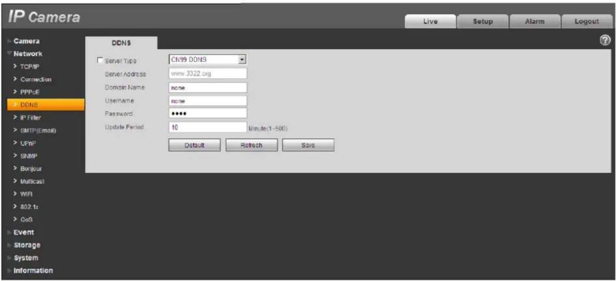
Figure 3-13
Please refer to the following sheet for detailed information.
| Parameter Function | |
| Server Type You | can select DDNS protocol from the dropdown list and then enable DDNS function. The QUICK DDNS protocol means you use your self-defined private protocol to realize DDNS function. |
| Server Address | DDNS server IP address |
| Domain Name | Your self-defined domain name. |
| Username | The user name you input to log in the server. |
| Password | The password you input to log in the server. |
| Update period | ● Device sends out alive signal to the server regularly.● You can set interval value between the device and DDNS server here. |
The QUICK DDNS interface is shown as in Figure 3-14.

Figure 3-14
| Parameter Function | |
| Server Type | You can select DDNS protocol from the dropdown list and then enable DDNS function. The QUICK DDNS means you use your self-defined private protocol to realize DDNS function. |
| Server Address D | DNS server IP address. Under DDNS the default server address is www.quickddns.com |
| Mode | The default is auto, and you can select manual. |
| Domain Name | Auto and self-defined domain names are both MAC address.quickddns.com. You can self-define prefix. |
| Test | It is to test domain name. It is available only under manual mode. |
| Username | The user name you input to log in the server. Optional. |
IP filter
The IP filter interface is shown as in Figure 3-15.
You can enable IP filter function so that some specified IP/MAC user can access the network camera.
You can add IP address or IP address section.
If you do not check the box here, it means there is on access limit.
Here you can add IP address and MAC address. You must add these address before enabling the trusted sites.
Please note: You must set MAC address in the same network segment.

Figure 3-4
SMTP (e-mail)
The SMTP interface is shown as in Figure 3-16.

Figure 3-5
Please refer to the following sheet for detailed information.
| Parameter Function | |
| SMTP Server | Input server address and then enable this function. |
| Port | Default value is 25. You can modify it if necessary. |
| Anonymity | For the server supports the anonymity function. You can auto login anonymously. You do not need to input the user name, password and the sender information. |
| User Name | The user name of the sender email account. |
| Password | The password of sender email account. |
| Sender | Sender email address. |
| Authentication (Encryption mode) | You can select SSL, TLS or none. |
| Title (Subject) | Input email subject here. |
| Attachment | System can send out the email of the snapshot picture once you check the box here. |
| Mail receiver | Input receiver email address here. Max three addresses. |
| Interval | The send interval ranges from 0 to 3600 seconds. 0 means there is no interval.Please note system will not send out the email immediately when the alarm occurs. When the alarm, motion detection or the abnormality event activates the email, system sends out the email according to the interval you specified here. This function is very useful when there are too many emails activated by the abnormality events, which may result in heavy load for the email server. |
| Health mail enable | Please check the box here to enable this function. |
| Update period (interval) | This function allows the system to send out the test email to check the connection is OK or not.Please check the box to enable this function and then set the corresponding interval.System can send out the email regularly as you set here. |
| Email test | The system will automatically sent out a email once to test the connection is OK or not .Before the email test, please save the email setup information. |
UPnP
It allows you to establish the mapping relationship between the LAN and the public network.
Here you can also add, modify or remove UPnP item. For UPnP on different routers, you must disable UPnP function. See Figure 3-17.
In the Windows OS, From Start->Control Panel->Add or remove programs. Click the "Add/Remove Windows Components" and then select the "Network Services" from the Windows Components Wizard.
Click the Details button and then check the "Internet Gateway Device Discovery and Control client" and "UPnP User Interface". Please click OK to begin installation.
Enable UPnP from the Web. If your UPnP is enabled in the Windows OS, the network camera can auto detect it via the "My Network Places".
Under manual mode, you can add, delete or modify mapping. Under auto mode, select idle port for auto port mapping without user modification.
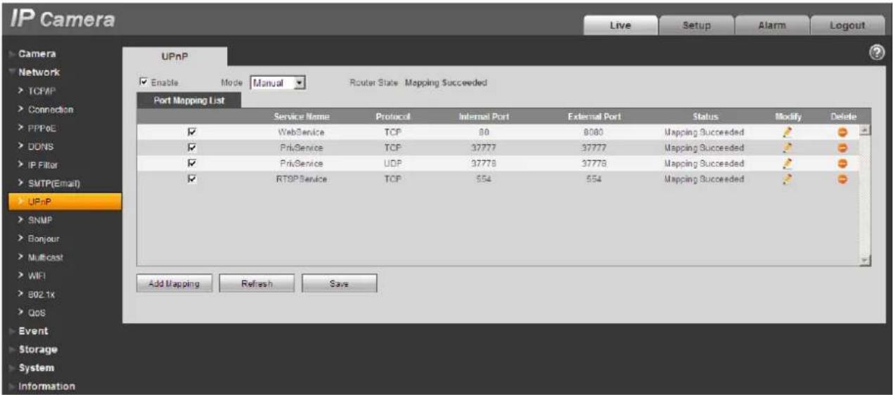
Figure 3-6
SNMP
The SNMP interface is shown as in Figure 3-18.
The SNMP allows the communication between the network management work station software and the proxy of the managed device. Please install the software such as MG MibBrowser 8.0c software or establish the SNMP service before you use this function. You need to reboot the device to activate the new setup.

Figure 3-7
Please refer to the following sheet for detailed information.
| Parameter Function | |
| SNMP port | The listening port of the proxy program of the device. It is a UDP port not a TCP port. The value ranges from 1 to 65535. The default value is 161 |
| Read community | It is a string. It is a command between the manage process and the proxy process. It defined the authentication, access control and the management relationship between one proxy and one group of the managers. Please make sure the device and the proxy are the same.The read community will read all the objects the SNMP supported in the specified name. The default setup is public. |
| Write community | It is a string. It is a command between the manage process and the proxy process. It defined the authentication, access control and the management relationship between one proxy and one group of the managers. Please make sure the device and the proxy are the same.The read community will read/write/access all the objects the SNMP supported in the specified name. The default setup is write. |
| Trap address | The destination address of the Trap information from the proxy program of the device. |
| Trap port | The destination port of the Trap information from the proxy program of the device. It is for the gateway device and the client-end PC in the LAN to exchange the information. It is a non-protocol connection port. It has no effect on the network applications. It is a UDP port not TCP port. The value ranges from 1 to 165535. The default value is 162. |
| SNMP version | ● SNMP V1: system only processes the information of V1.● SNMP V2: system only processes the information of V2.● SNMP V3: you can set user name and password. There is account security verification when the server wants to connect to the device. At the same time, the v1 and V2 is null and cannot select. |
| Username read-only | Only when SNMP version is SNMP v3, you shall config this parameter. The default is public. |
| Authentication | Only when SNMP version is SNMP v3, you shall config this parameter. You can select either MD5 or SHA. The default is MD5. |
| Authentication password | Only when SNMP version is SNMP v3, you shall config this parameter. Password requires min of 8 characters. |
| Encryption | Only when SNMP version is SNMP v3, you shall config this parameter. The default is CBC-DES. |
| Encryption password | Only when SNMP version is SNMP v3, you shall config this parameter. Password requires min of 8 characters. |
| Username read/write | Only when SNMP version is SNMP v3, you shall config this parameter. The default is private. |
| Authentication | Only when SNMP version is SNMP v3, you shall config this parameter. You can select either MD5 or SHA. The default is MD5. |
| Authentication password | Only when SNMP version is SNMP v3, you shall config this parameter. Password requires min of 8 characters. |
| Encryption | Only when SNMP version is SNMP v3, you shall config this parameter. The default is CBC-DES. |
| Encryption password | Onlywhen SNMP version is SNMP v3, you shall config this parameter. Password requires min of 8 characters. |
Bonjour
The Bonjour interface is shown as below. See Figure 3-19.
Bonjour is based on the multicast DNS service from the Apple. The Bonjour device can automatically broadcast its service information and listen to the service information from other device.
You can use the browse of the Bonjour service in the same LAN to search the network camera device and then access if you do not know the network camera information such as IP address.
You can view the server name when the network camera is detected by the Bonjour. Please note the safari browse support this function. Click the "Display All Bookmarks: and open the Bonjour, system can auto detect the network camera of the Bonjour function in the LAN.
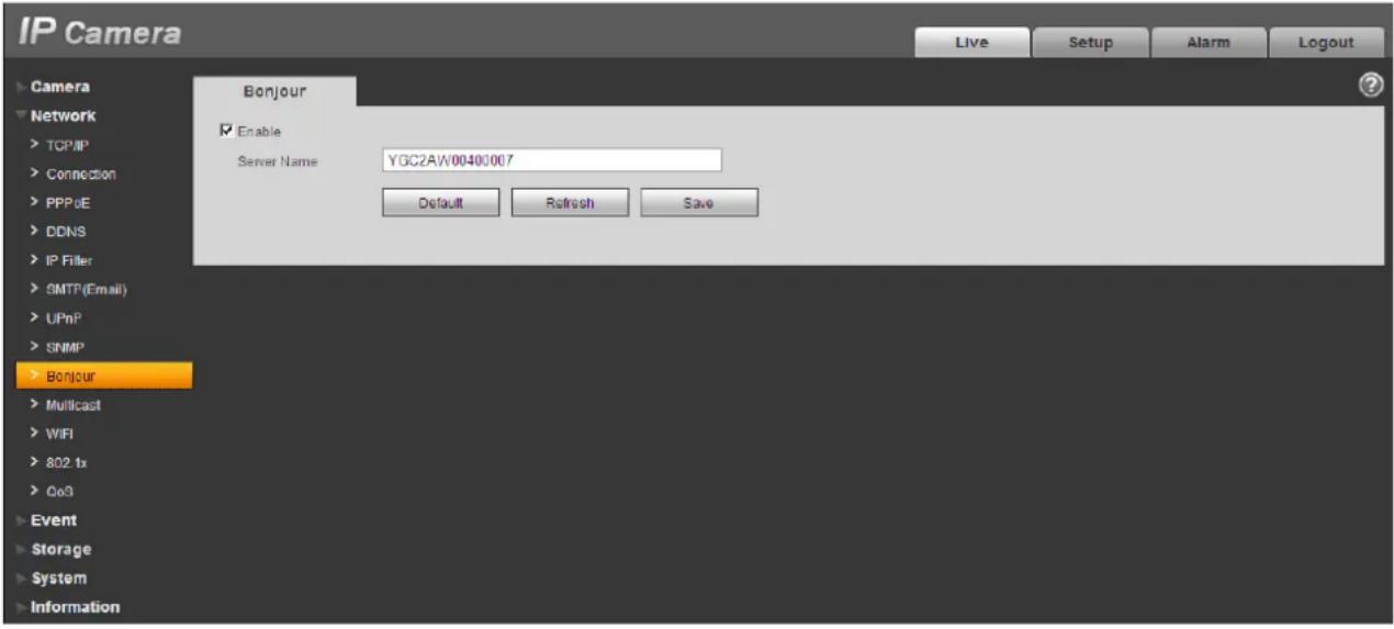
Figure 3-19
Multicast
The multicast interface is shown as in Figure 3-20.
Multicast is a transmission mode of data packet. When there is multiple-host to receive the same data packet, multiple-cast is the best option to reduce the broad width and the CPU load. The source host can just send out one data to transit. This function also depends on the relationship of the group member and group of the outer.
Here you can set multicast address and port. You also need to go to Live interface to set the protocol as Multicast.

Figure 3-20
Please refer to the following sheet for detailed information.
| Parameter Function | |
| Enable | Select to enable multicast function. Main stream and sub stream cannot be used at the same time. |
| Multicast address | Main/sub stream multicast address is 239.255.42.42 and its range is 224.0.0.0~239.255.255.255. |
| Port | Multicast port. Main stream is 36666, sub stream is 36667and the range is 1025~65534. |
802.1x
802.1x (port based network access control protocol) supports manual selection of authentication method to control if device connected to LAN can join the LAN. It well supports authentication, charging, safety and management requirement of network.
See Figure 3-21.
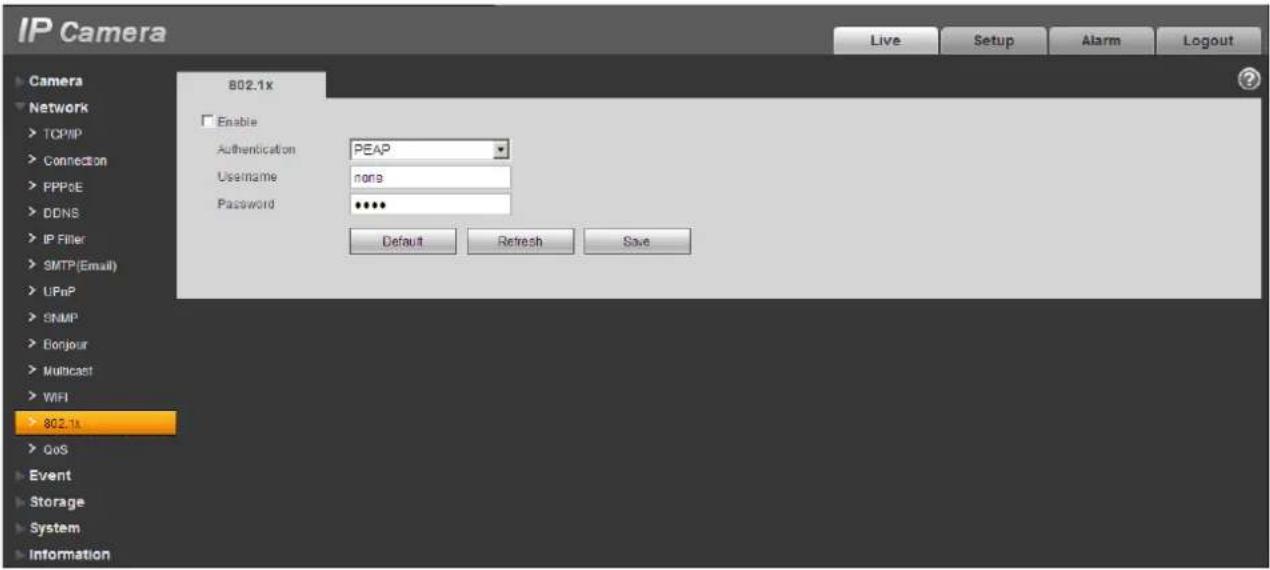
Figure 3-21
Please refer to the following sheet for detailed information.
| Parameter Function | |
| Authentication | PEAP (protected EAP protocol). |
| Username | It needs the username to login, which is authenticated by the server. |
| Password | Please input password here. |
QoS
The QoS interface is shown as below. See Figure 3-22.
Qos (Quality of Service) is network security mechanism. It is a technology to fix the network delay and jam problem and etc. For the network service, the quality of service includes the transmission bandwidth, delay, the packet loss and etc. We can guarantee the transmission bandwidth, lower the delay, reduce the loss of the data packet and anti-dither to enhance the quality.
We can set the DSCP (Differentiated Services Code Point) of the IP to distinguish the data packet so that the router or the hub can provide different services for various data packets. It can select the different queues according to the priority of the packets and select the bandwidth of the each queue. It can also discard at the different ratio when the broad bandwidth is jam.
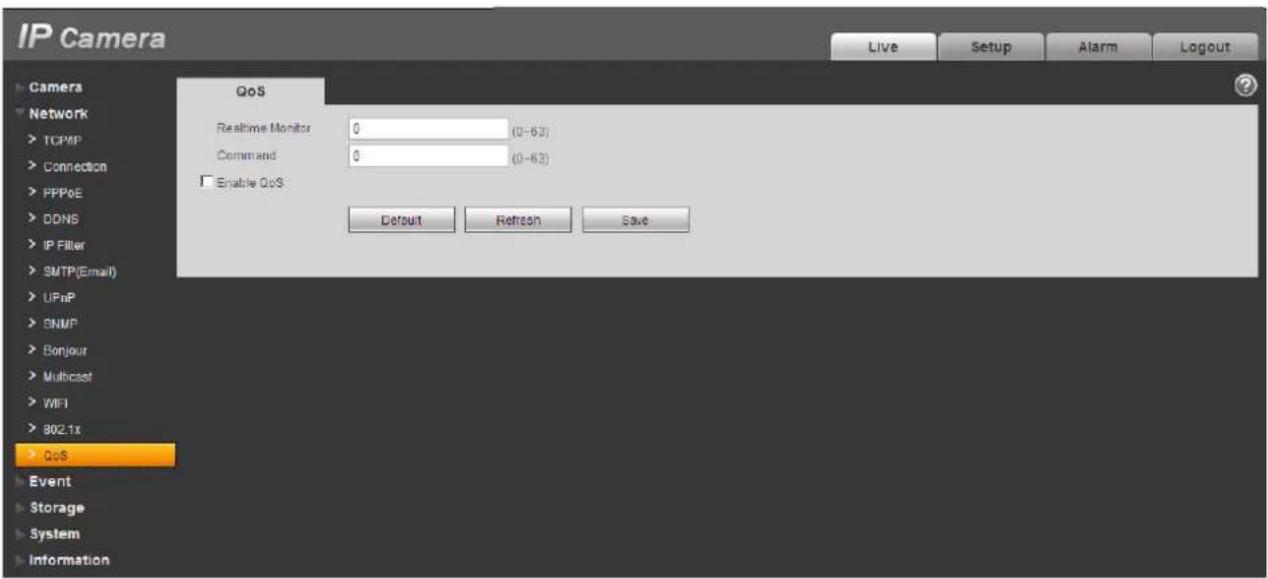
Figure 3-22
Please refer to the following sheet for detailed information.
| Parameter Function | |
| Real-time monitor | The value ranges from 0 to 63. The router or the switcher can provide different service for various data packets. |
| Command | The value ranges from 0 to 63. The router or the switcher can provide different service for various data packets. |
| Enable wireless QoS | Check it to enable QoS. |
Event
Video detect
Motion Detect
The motion detect interface is shown as in Figure 3-23.

Figure 3-23
Please refer to the following sheet for detailed information.
| Parameter Function | |
| Enable | You need to check the box to enable motion detection function. |
| Working Period | Here you can set arm/disarm period. Click on set button to open period setup menu.There are six periods every day for setup and you must check box in front of each period to enable it. |
| Anti-dither | System only memorizes one event during the anti-dither period.The value ranges from 0s to 100s. |
| Area | Here you can set motion detection region and its sensitivity and area. (The higher the sensitivity is, the easier to trigger motion detect; the smaller the area, the easier to trigger motion detect.)The default covers all regions. You must click on save before enabling your setup. |
| Record | Check it and so when alarm occurs, system will auto record. You shall set record period in Storage>Schedule and select auto record in record control interface. |
| Record Delay | System can delay the record for specified time after alarm ended.The value ranges from 10s to 300s. |
| Relay out | Enable alarm activation function. You need to select alarm output port so that system can activate corresponding alarm device when alarm occurs. |
| Alarm Delay | System can delay the alarm output for specified time after alarm ended. The value ranges from 10s to 300s. |
| Send Email | If you enabled this function, System can send out email to alert you when alarm occurs and ends. User can set email address in Network>SMTP. |
| PTZ | ● Here you can set PTZ movement when alarm occurs. Such as go to preset x when there is an alarm.● The event type includes: preset, tour and pattern. |
| Snapshot | You need to check the box here so that system can backup motion detection snapshot file. |
See Figure 3-24.

Figure 3-24
See Figure 3-25.

Figure 3-25
Different colors represent different areas. Each area can set different detection zones. Detection zone cam be irregular and discontinuous. If device monitoring zone is large, user can sub-divide the area into several zones for better motion detect.
Please refer to the following sheet for detailed information.
| Parameter Function | |
| Name | Default area name includes Region0, Region1, Region2, Region3 and custom. |
| Sensitivity | It is sensitivity of brightness as motion detection is more possible to be trigger with high sensitivity. You can set up to four areas. The range is 0~100. The recommenced value is 30~70. |
| Area threshold It | is to check target object area related to detection area. The lower the area threshold, the easier to trigger motion detection. You can set up to four areas. The range is 0~100. The recommenced value is 0~10. |
| Waveform | Red means motion detect is triggered. Green means motion detect is not triggered. |
| Delete all | Clear all areas. |
| Delete Delete selected area. | |
Video Masking
The video masking interface is shown as in Figure 3-30.

Figure 3-30
Please refer to the following sheet for detailed information.
| Parameter Function | |
| Enable | You need to check the box to enable this function. |
| Working period | You need to set arm and disarm time. Click on setup button to set. |
| Record | After record is enabled, video masking can activate video. |
| Record delay System | System can delay the record for specified time after alarm ended.The value ranges from 10s to 300s. |
| Relay out | Enable alarm activation function. You need to select alarm output port so that system can activate corresponding alarm device when alarm occurs. |
| Alarm delay | System can delay the alarm output for specified time after alarm ended. The value ranges from 10s to 300s. |
| Send Email If you enabled this function, System can send out email to alert you when alarm occurs. | |
| Snapshot | After snapshot is enabled and alarm happens, the system will automatically snapshot and alarm. |
Abnormity
Note:
Only device with SD card function has these three statuses: No SD card, capacity warning, SD card error.
Device without SD card function does not have the above three statuses. See Figure 3-31 through Figure 3-35.

Figure 3-31

Figure 3-32

Figure 3-33

Figure 3-34
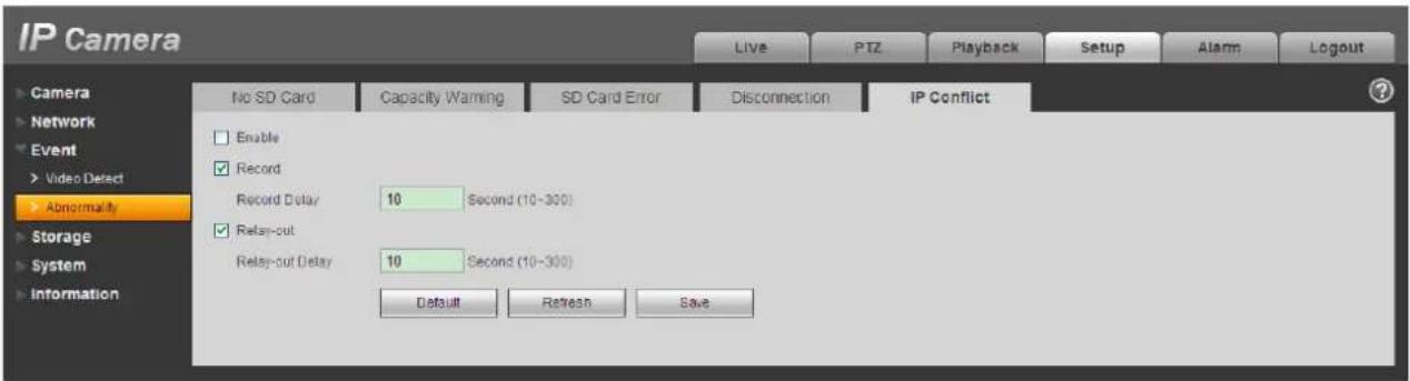
Figure 3-35
Please refer to the following sheet for detailed information.
| Parameter | Function |
| Event Type | The abnormal events include: no disk, no space, disk error, net error, offline, IP conflict.Threshold: You can set the minimum percentage value here. The device can alarm when capacity is not sufficient.You need to draw a circle to enable this function. |
| Record | System auto activates channel to record once alarm occurs (For offline type only. See Figure 2-.).You need to check the box to enable this function. |
| Record delay | System can delay the record for specified time after alarm ended. The value ranges from 10s to 300s. |
| Relay Out | The corresponding alarm output channel when alarm occurs. You need to check the box to enable this function. |
| Relay out delay | The alarm output can delay for the specified time after alarm stops. The value ranges from 10s to 300s. |
| Send email | After you enabled this function, the system can send out email to alarm the specified user.This function is invalid when network is offline or IP conflict occurs. |
Storage
Record Schedule and Snapshot Schedule
In these two interfaces, you can add or remove the schedule record/snapshot setup. See Figure 3-36.
There are three record modes: general (auto), motion detect and alarm. There are six periods in one day. Please make sure you have enabled the corresponding record mode in the Setup->Storage->Conditions.
You can view the current time period setup from the color bar.
- Green color stands for the general record/snapshot.
- Yellow color stands for the motion detect record/snapshot..
- Red color stands for the alarm record/snapshot.
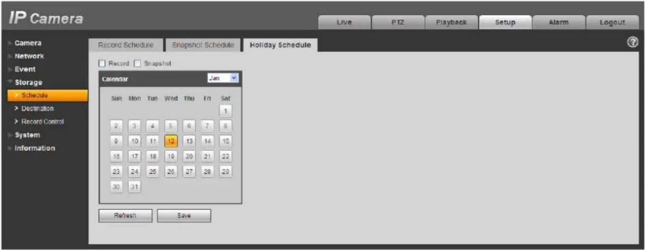
Figure 3-36
You can set specified dates as holiday. When snapshot of holiday is enabled, the selected dates will be snapshot/recorded according to holiday setup.
Destination
The destination interface is shown as in Figure 3-37.
It is to set the storage mode of the network camera record file or snapshot pictures. System can save according to the event types. It is corresponding to the three modes (general/motion) in the Schedule interface. Please check the box to enable the save functions.
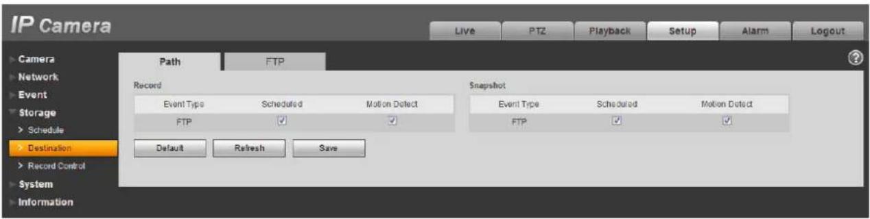
Figure 3-37
Please refer to the following sheet for detailed information.
| Parameter | Function |
| Event Type | It includes: general, motion detect and alarm. |
| FTP It saved in the FTP server. | |

Figure 3-38
Record control
The record control interface is shown as in Figure 3-39.

Figure 3-39
Please refer to the following sheet for detailed information.
| Parameter Function | |
| Pack Duration | Here you can select file size. Default setup is 8 minutes. |
| Pre-record | Please input pre-record value here.For example, system can record the four seconds video in the buffer.The record begins from the fifth second. |
| Disk Full | There are two options: stop recording or overwrite the previous files when HDD is full.Stop: Current working HDD is overwriting or current HDD is full, it will stop record.Overwrite: Current working HDD is full; it will overwrite the previous file. |
| Record mode | There are three modes: Auto/manual/close. |
| Record stream | There are two options: main stream and sub stream. |
System
General
The general interface includes the local host setup and the date/time setup.
Local host
The local host interface is shown as in Figure 3-40.
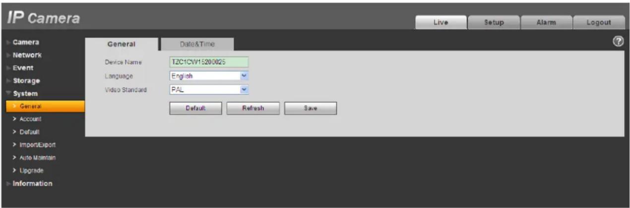
Figure 3-40
Please refer to the following sheet for detailed information.
| Parameter Function | |
| Device No | It is to set device name. |
| Video Standard | This is to display video standard such as PAL. |
| Language | You can select the language from the dropdown list. |
Date and time
The date and time interface is shown as in Figure 3-41.
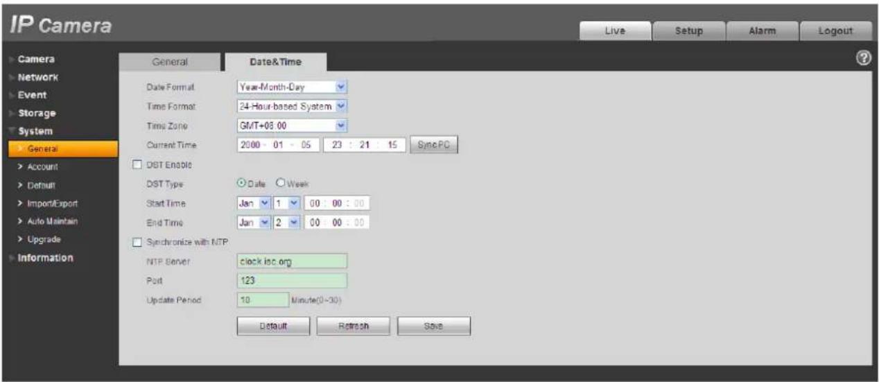
Figure 3-41
Please refer to the following sheet for detailed information.
| Parameter Function | |
| Date format | Here you can select date format from the dropdown list. |
| Time Format | There are two options: 24-H and 12-H. |
| Time zone | The time zone of the device. |
| System time | It is to set system time. It becomes valid after you set. |
| Sync PC | You can click this button to save the system time as your PC current time. |
| DST | Here you can set day night save time begin time and end time. You can set according to the date format or according to the week format. |
| NTP You can check the box to enable NTP function. | |
| NTP server | You can set the time server address. |
| Port | It is to set the time server port. |
| Update period | It is to set the sync periods between the device and the time server. |
Account
Note
For the character in the following user name or the user group name, system max supports 15-digits. The valid string includes: character, number, and underline.
The user amount is 18 and the group amount is 8 when the device is shipped out of the factory. The factory default setup includes two levels: user and admin. You can set the corresponding group and then set the rights for the respective user in the specified groups.
User management adopts group/user modes. The user name and the group name shall be unique. One user shall be included in only one group.
User name
In this interface you can enable anonymity login, add/remove user and modify user name. See Figure 3-42.
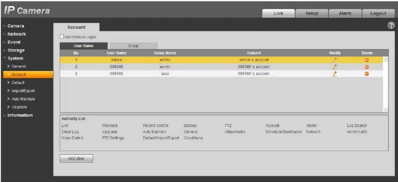
Figure 3-42
Enable anonymity login: Enable anonymity login, and input IP. No username or password is required, you can log in by anonymity (with limited rights). You can click logout to end your session.
Add user: It is to add a name to group and set the user rights.
Hidden user "default" is for system interior use only and cannot be deleted. When there is no login user, hidden user "default" automatically login. You can set some rights such as monitor for this user so that you can view some channel view without login.
Here you can input the user name and password and then select one group for current user.
Please note the user rights shall not exceed the group right setup.
For convenient setup, please make sure the general user has the lower rights setup than the admin.

Figure 3-43
Modify user
It is to modify the user property, belonging group, password and rights. See Figure 3-.44
Modify password
It is to modify the user password. You need to input the old password and then input the new password twice to confirm the new setup. Please click the OK button to save.
Please note, the password ranges from 0-digit to 32-digit. It shall include the number and letter only. For the user who has the account rights, he can modify the password of other users.

Figure 3-44
Group
The group management interface can add/remove group, modify group password and etc.
The interface is shown as in Figure 3-45.
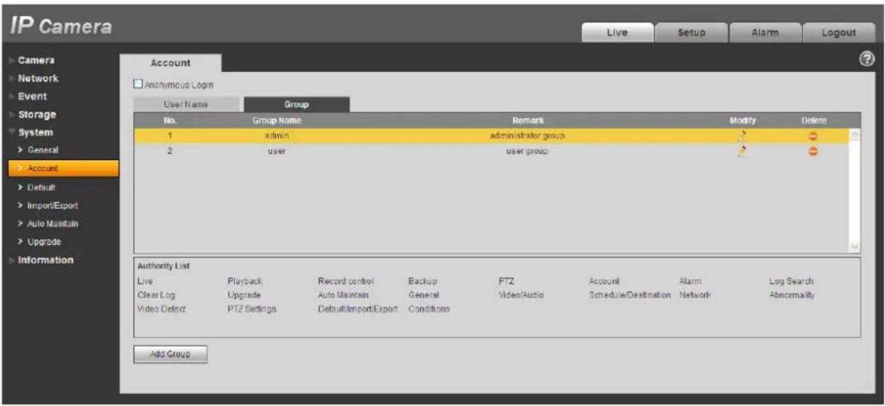
Figure 3-45
Add group: It is to add group and set its corresponding rights. See Figure3-46.
Please input the group name and then check the box to select the corresponding rights. It includes: preview, playback, record control, PTZ control and etc.
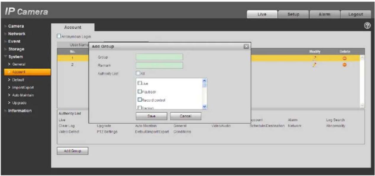
Figure 3-47
Modify group
Click the modify group button, you can see an interface is shown as in Figure 3-48.
Here you can modify group information such as remarks and rights.

Figure 3-48
Default
The default setup interface is shown as in Figure 3-49.
Please note system cannot restore some information such as network IP address.

Figure 3-49
Import/Export
The interface is shown as in Figure 3-50

Figure 3-50
Please refer to the following sheet for detailed information.
| Parameter | Function |
| Import | It is to import the local setup files to the system. |
| Export | It is to export the corresponding system setup to your local PC. |
Auto Maintenance
The auto maintenance interface is shown as in Figure 3-51.
Here you can select auto reboot and auto delete old files interval from the dropdown list.
If you want to use the auto delete old files function, you need to set the file period.

Figure 3-51
Upgrade
The upgrade interface is shown as in Figure 3-52.
Please select the upgrade file and then click the update button to begin firmware update.
CAUTION
Improper upgrade program may result in device malfunction.

Figure 3-52
Information
Version
The version interface is shown as in Figure 3-53.
Here you can view system hardware features, software version, release date and etc. Please note the following information is for reference only.

Figure 3-53
Log
Here you can view system log. See Figure 3-54.

Figure 3-54
Please refer to the following sheet for log parameter information.
| Parameter | Function |
| Type | Log types include: system operation, configuration operation, data operation, event operation, record operation, user management, log clear. |
| Start time | Set the start time of the requested log. |
| End time | Set the end time of the requested log. |
| Search | You can select log type from the drop down list and then click search button to view the list.You can click the stop button to terminate current search operation. |
| Log information | You can select one item to view the detailed information. |
| Clear | You can click this button to delete all displayed log files. Please note system does not support clear by type. |
| Backup | You can click this button to backup log files to current PC. |
Online User
The online user interface is shown as in Figure 3-55.
Here you can view current online user, group name, IP address and login time.

Figure 3-55
Note
Some models do not support this function.
Click alarm function, you can see an interface is shown as in Figure 4-1.
Here you can set device alarm type and alarm sound setup.

Figure 4-1
Please refer to the following sheet for detailed information.
| Type | Parameter | Function |
| Alarm type | Motion detection | System alarms when motion detection alarm occurs, |
| Camera masking | System alarms when camera is viciously masking. | |
| Operation | Prompt | System automatically pops up alarm dialogue box. |
| Alarm audio | Audio | When alarm occurs, system auto generates alarm audio. The audio supports customized setup. |
| Path | Here you can specify alarm sound file. |
Click log out button, the system goes back to the log in interface. See Figure5-1.

Figure 5-1
Note
This manual is for reference only. Slight difference may be found in user interface.
All the designs and software here are subject to change without prior written notice.
All trademarks and registered trademarks mentioned are the properties of their respective owners.
If there is any uncertainty or controversy, please refer to the final explanation of us.
Please visit our website for more information.
- Illustra Essentials Network Camera Web3.0 User Manual
- Notice
- Copyright
- Customer Service
- Trademarks
- Table of Contents
- Storage 43
- System....46
- Information....54
- Alarm 56
- Log out ....57
- Log in
- Note
- Live Interface
- Encode Setup
- System Menu
- Video Window Function Option
- Video Window Setup
- Hide Image Control
- Original size
- Full screen
- Width and height ratio
- Fluency Adjustment
- Image control
- Camera
- Conditions
- Note:
- Video
- Video bit stream
- Snapshot
- Video Overlay
- Path
- Network
- TCP/IP
- Connection
- PPPoE
- DDNS
- IP filter
- SMTP (e-mail)
- UPnP
- SNMP
- Bonjour
- Multicast
- 802.1x
- QoS
- Event
- Video detect
- Motion Detect
- Video Masking
- Abnormity
- Storage
- Record Schedule and Snapshot Schedule
- Destination
- Record control
- System
- General
- Local host
- Date and time
- Account
- User name
- Modify user
- Modify password
- Group
- Modify group
- Default
- Import/Export
- Auto Maintenance
- Upgrade
- CAUTION
- Information
- Version
- Log
- Online User
Brand : Tyco
Model : Illustra Essentials IES02D1OCWIYB
Category : Surveillance Camera