
CCTV-2000 - Alarm system Steren - Free user manual and instructions
Find the device manual for free CCTV-2000 Steren in PDF.


| Type | CCTV Security Camera System (Alarm System) |
| Model | CCTV-2000 |
| Brand | Steren |
| Camera Resolution | 1080p (1920 x 1080) |
| Night Vision | Infrared LEDs, up to 20 m range |
| Field of View | 90° |
| Storage | microSD card up to 128 GB (not included) |
| Power Supply | DC 12V / 1A |
| Connectivity | BNC video output, Ethernet (PoE optional) |
| Motion Detection | Yes, configurable sensitivity |
| Audio | Two-way audio via built-in microphone and speaker |
| Operating Temperature | -10°C to 50°C |
| Dimensions (camera) | 70 x 70 x 120 mm |
| Weight (camera) | 300 g |
| Warranty | 1 year |
| Included Accessories | Cameras, power adapters, BNC cables, mounting kit, user manual |
| Cleaning and Maintenance | Wipe with a dry, soft cloth; avoid harsh chemicals |
| Safety | Low voltage device; keep away from water |
| Spare Parts Availability | Contact Steren support for compatible parts |
| General Information | Designed for indoor/outdoor use with IP66 rating (estimated) |
Frequently Asked Questions - CCTV-2000 Steren
User questions about CCTV-2000 Steren
0 question about this device. Answer the ones you know or ask your own.
Ask a new question about this device
Download the instructions for your Alarm system in PDF format for free! Find your manual CCTV-2000 - Steren and take your electronic device back in hand. On this page are published all the documents necessary for the use of your device. CCTV-2000 by Steren.
USER MANUAL CCTV-2000 Steren
natural_image
Illustration of a smart security camera with two antennas and a mounted device (no text or symbols)natural_image
Illustration of various household appliances including a remote control, a handheld device, and four green screw-like fixtures (no text or symbols)Sensores PIR

natural_image
Illustration of four different types of electrical connectors and screw fasteners (no text or symbols)Sensores magnéticos
natural_image
Illustration of mechanical components including cylindrical cylinders, rectangular blocks, screw and nut arrangements, and four circular components (no text or symbols)Controles

natural_image
Two identical medical device diagrams with purple and gray buttons, no text or symbols presentDESCRIPCIÓN GENERAL
natural_image
Line drawing of a remote control device with a green arrow indicating left motion (no text or symbols)
natural_image
Diagram of a battery internal structure showing internal components and an external cylinder (no text or symbols)natural_image
Line drawing of a simple rectangular device with a curved top and two small circular components on the side (no text or symbols)natural_image
Line drawing of a battery and a pliers (no text or symbols)Control remoto
natural_image
Line drawing of a medical or laboratory device with a screen, screw, and oval base (no text or symbols)CONEXIONES
DESCARGAR LA APP Y REGISTRAR UNA CUENTA


Sensor magnético
natural_image
Illustration of a mobile phone with a hand gesture pointing at the button (no text or symbols)natural_image
Illustration of a hand pressing a button on a device panel (no text or symbols visible)En caso de que la
natural_image
Diagram of a hand gesture inside a device with purple and green signal lines (no text or symbols)Control remoto
2
natural_image
Technical line drawing of a mechanical component with two bolts and mounting holes (no text or symbols)2
natural_image
Technical line drawing of a mechanical clamp or bracket with two bolts and two end caps (no text or symbols)
natural_image
Simple line drawing of a vertical pipe or pipe assembly with two vertical connectors (no text or symbols)ESPECIFICACIONES
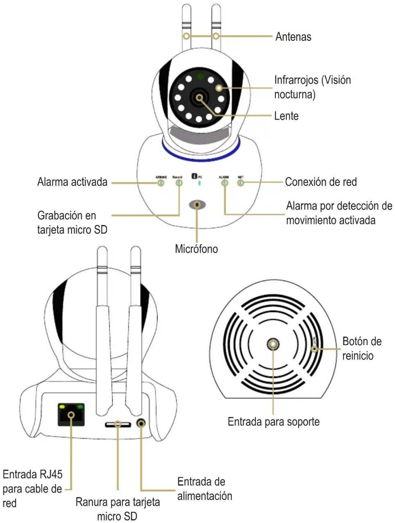
Cámara
natural_image
Illustration of a smart security camera with two antennas and a mounted device (no text or symbols)User Manual
CCTV-2000
Before to use the product, please read carefully this manual to avoid any malfunction.
The info in this manual is shown as reference.
Due to updates can exist differences. Consult our website www.steren.com to obtain the current version of this manual.
CAUTIONS
- This product is NOT a toy; keep it away from children.
- This device cannot be used by people with different abilities, unless they have preparation and supervision.
- The company is not responsible by bad use of the content with this product.
- Don't remove the microSD card while the camera is recording, may cause mal function and losing data.
- Don't place heavy objects over the camera.
- Don't use abrasive liquids to clean it.
- Don't install it near magnetic objects or emits that noise.
- Don't expose the camera to water or humidity.
- Don't install outdoor.
The operation of this equipment is subject to the following two conditions: (1) it is possible that this equipment or device may not cause harmful interference and (2) this equipment or device must accept any interference, including interference that may cause its undesired operation
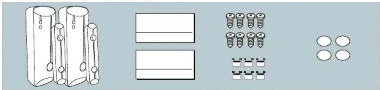
CONTENT
Camera
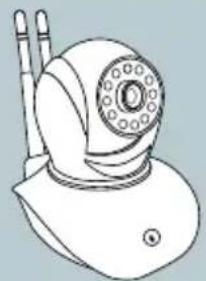
natural_image
Line drawing of a snail with a circular head and two antennae (no text or symbols)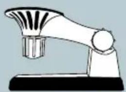
natural_image
Line drawing of a kitchen utensil with a conical handle and base (no text or symbols)
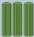
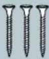
PIR Sensors

natural_image
Line drawing of a handheld mobile phone with antenna (no text or symbols)

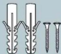
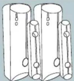
Magnetic sensors
natural_image
Three cylindrical objects with hanging pins, arranged side by side (no text or symbols)
natural_image
Two empty rectangular boxes with horizontal lines, no text or symbols present

Controls

natural_image
Simple line drawing of a medical or electronic device with no text, numbers, or symbols
natural_image
Illustration of a mobile phone with control buttons and a red star (no text or symbols)GENERAL DESCRIPTION
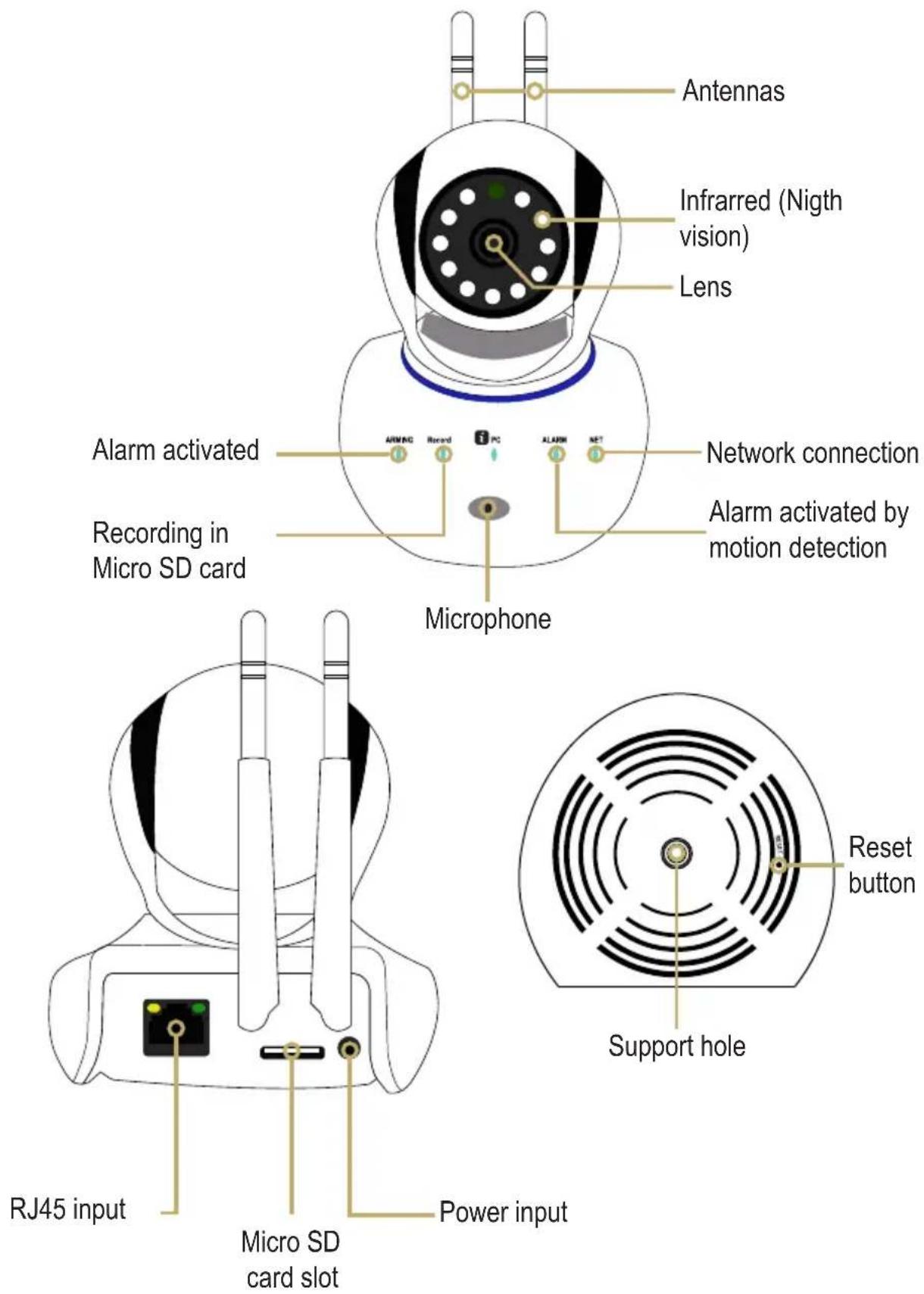
BATTERIES PLACEMENT
Magnetic sensor
Slide the cover and insert a "AA" battery in the compartment. Place the cover again.

natural_image
Line drawing of a remote control device with a green arrow indicating left motion (no text or symbols)
natural_image
Diagram of a battery internal structure showing internal components and an external cylinder (no text or symbols)Move sensor
Remove the bottom screw of the sensor to remove the cover.

natural_image
Line drawing of a simple rectangular device with a curved top and two small buttons at the bottom (no text or symbols)Pull up the fastener. Connect a 9 V battery and adjust into the compartment. Place the cover again.

natural_image
Line drawing of a battery and a plug (no text or symbols)Remote control
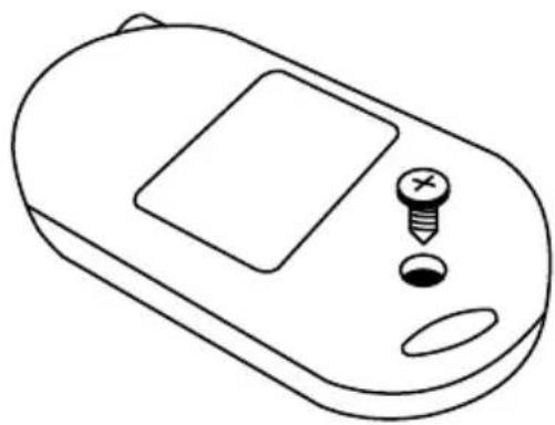
Remove the screw, and insert a 27A battery. Place a cover again.
natural_image
Line drawing of a medical or laboratory device with a screen, screw, and oval base (no text or symbols)CONNECTIONS
Connect the camera into an outlet.
Use a network cable to connect the camera to the modem.

APP DOWNLOAD AND ACCOUNT REGISTER
To monitor, you must install the iEye-camera app; download it from the app store of your mobile device.

This app is not property of Steren; the company is not responsible for the malfunction or updates.
Open the app. The first time you must create a personal account. Use the Mailbox / user ID option.

flowchart
graph TD
    A["Account logon"] --> B["Mailbox/user ID"]
    A --> C["Mobile phone number"]
    A --> D["Please enter the mailbox /ID"]
    A --> E["Please enter the password"]
    A --> F["Login"]
    F --> G["Forget password"]
    G --> H["Press to confirm"]
    I["Enter an e-mail"] --> J["Enter a password"]
The showed images corresponding to an iOS device and the iEye-camera app (03.24.02.00), it is only for reference.
CONFIGURATION
-
With the camera online, enter to the app. After a few seconds will appears the message: Discover 1 new device; press > to continue.
-
Will appears the ID number of the camera. Press +
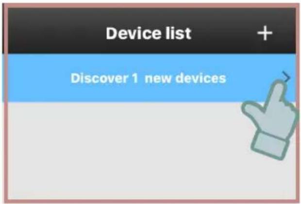

- Assign a name to identify the camera and enter the default password: 123456. Press Save to continue.

MONITORING
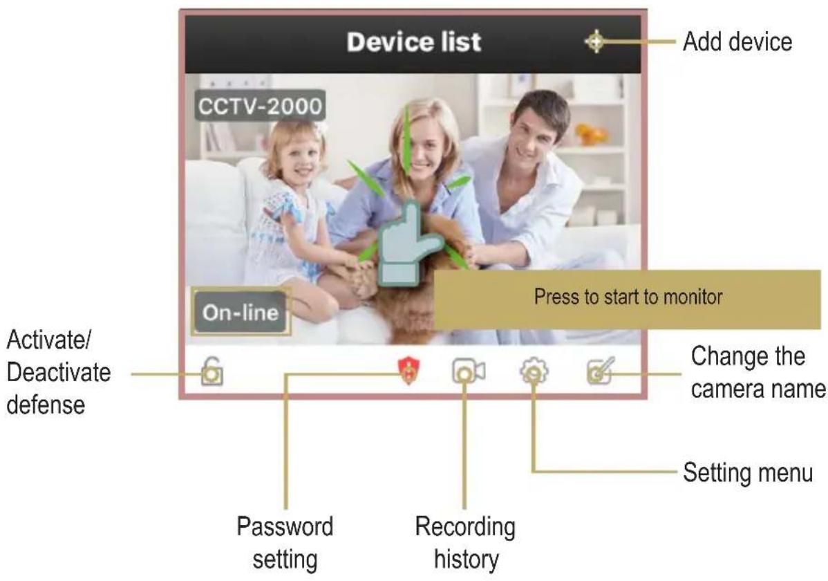
When the On-line message appears, it means that the camera it's ready to be used.
flowchart
graph TD
    A["Lock Icon"] --> B["Pad Icon"]
    B --> C["Signal Path"]
    D["Red Dot"] --> E["Load Signal"]
    F["Gray Circle"] --> G["Control Signal"]
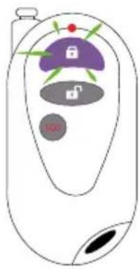
If you activate the alarm (alert armed) with the remote control, you must wait approx 50 seconds to save the changes.
It's recommendable to use the app for activate / deactivate the alerts.
Next, you can monitor in real time and control the camera movements.
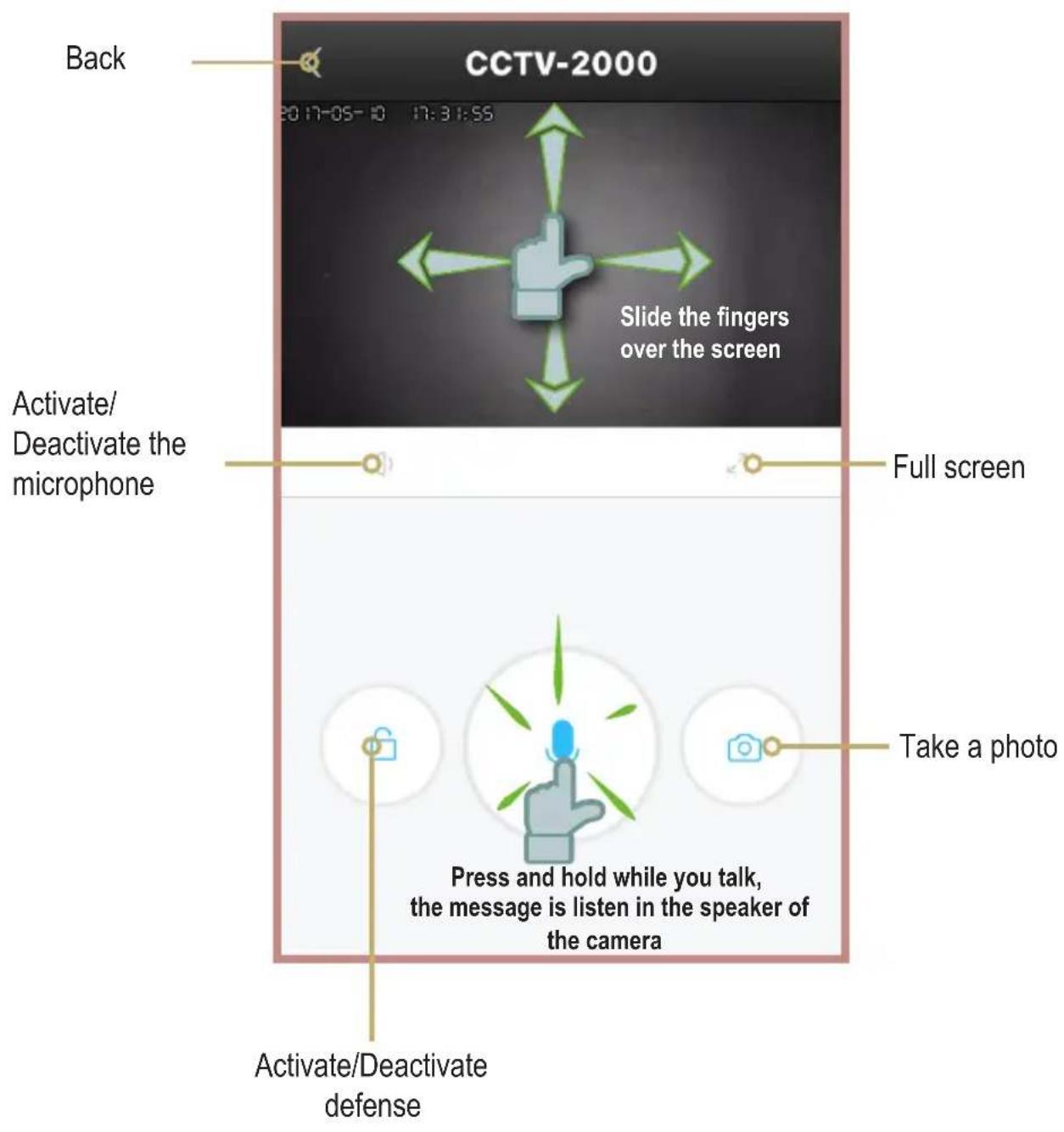
! Always adjust the vision angle of vision with the app. If you turn the camera manually, may cause internal damages.
PAIRING THE SENSORS AND THE REMOTE CONTROL
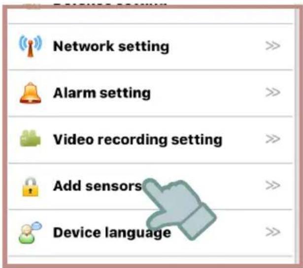
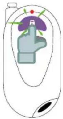
- Enter to setting menu and select Add sensors.
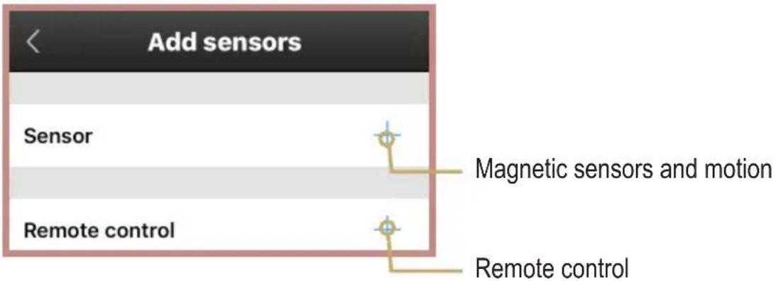
- Press + to select the device type (sensor or remote control).
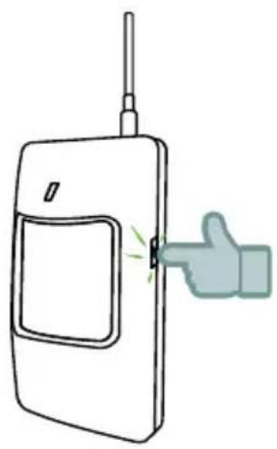
- When the follow message appears, turn on the selected device and press Confirmed.


Magnegtic sensor
natural_image
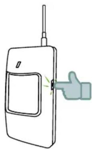
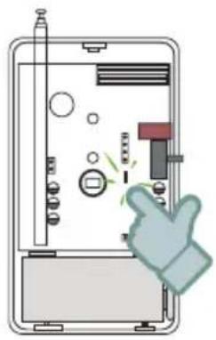
Illustration of a mobile phone with a green thumbs-up gesture (no text or symbols)Motion sensor If the motion sensor
natural_image
Illustration of a device with a hand gesture pointing at a button (no text or symbols present)fails while pairing, repeat the previous steps and press the internal button.
natural_image
Diagram of a human hand with finger pointing at a purple and green interface (no text or symbols)Remote control
Wait until the search is over. If the device is correctly added, you will see in the list. Remember that you must configure the alerts to receive notifications in the smartphone and activate the motion detection. Consult the “Activate Alerts” section in this manual.
ACTIVATE ALERTS
-
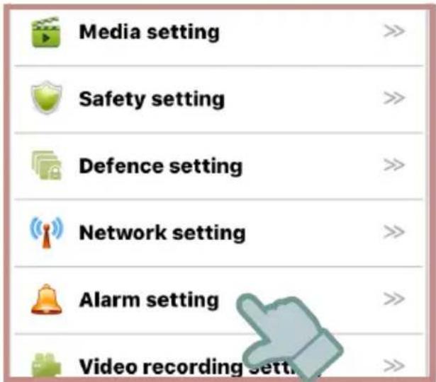
Enter to setting menu. Select Alarm setting.
-
Activate or deactivate the options that you want.
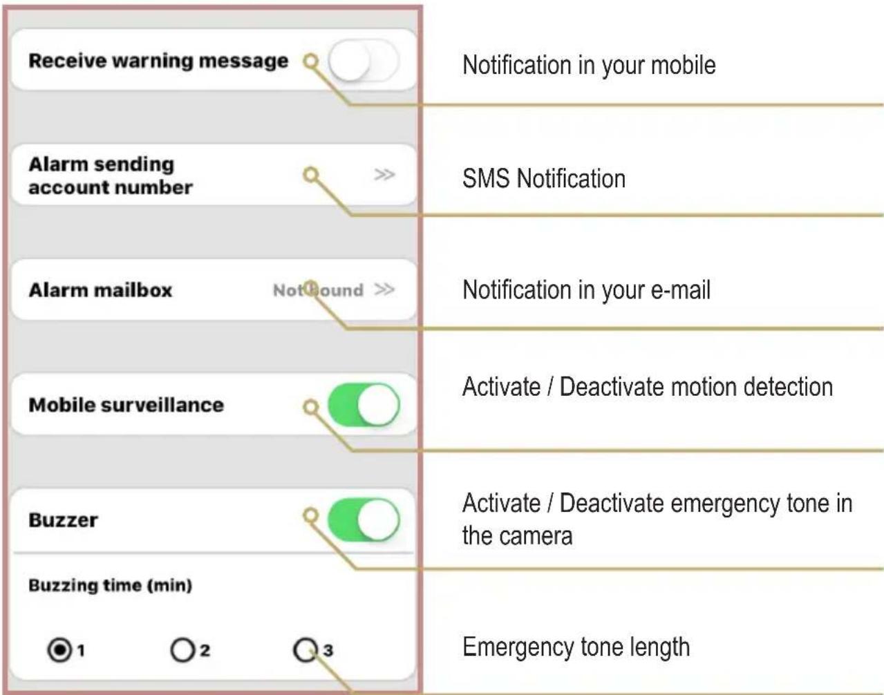
If you have activate the notifications in your mobile device, you will receive alerts according with the selected configuration.

Slide to watch
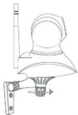
INSTALLATION
Camera

natural_image
Line drawing of a hand using a tool to adjust or install a mechanical component (no text or symbols present)1

natural_image
Line drawing of a hand holding a drill bit with a screwdriver, no text or symbols present

3

natural_image
Technical line drawing of a mechanical bracket with mounting holes and a base (no text or symbols)4
natural_image
Technical line drawing of a mechanical device with a lever and base mount (no text or symbols)5
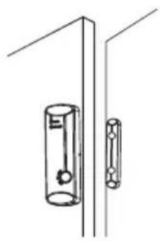
Magnetic sensor
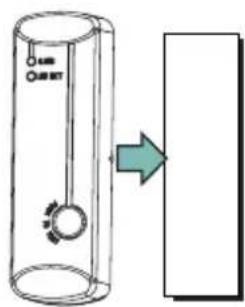
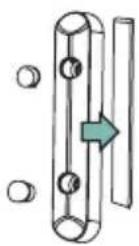
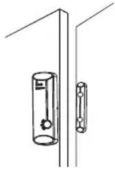
Option 1 (with the adhesive plates)
1
Paste the sensor and the magnetic element over the plates.
2
Remove the protector cover from the plate and paste the detector (A) in the door's frame; repeat the same process for the magnetic element (B). Ensure that the triangular marks must be aligned.
Remember: The distance between both parts of the sensor don't must exceed 15 mm!


natural_image
Simple line drawing of a vertical pipe or pipe assembly with a cylindrical component and a side-mounted rod (no text or symbols)Option 2 (with the screws)
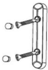
1
Remove the cover from the detector and screw it in the door's frame.
2
Assembly the detector (A) again.

natural_image
Technical line drawing of a door handle with screw and lever (no text or symbols)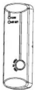
3
Screw the magnetic element (B) in the door. Ensure that the triangular marks must be aligned. Remember: The distance between both parts of the sensor don't must exceed 15 mm!
natural_image
Simple line drawing of a mechanical bracket with two bolts and two end caps (no text or symbols)
natural_image
Simple line drawing of a vertical support structure with two vertical bars (no text or symbols)Motion sensor

SPECIFICATIONS
Camera
Input: 5 V --- 2 A
Minimum light: 0.5 lux
Video compression: H.264 720p
Video: 25 fps and 30 fps
Audio format: G.726
Protocol: TCP/IP
Wireless network: 802.11b/g/n
Maximum micro SD card capacity: 64 GB
Door sensor
Input: 1.5 V --- (1 x AA)
Stand-by current: < 2.5 μA
Operating current: < 30 mA
Operating frequency: 433 MHz
Range: up to 60 m (open area)
Motion sensor
Input: 9 V --- (1 x 6RL61)
Stand-by current: < 25 μA
Operating current: < 15 mA
Detection angle: 110^
Operating frequency: 433 MHz
Range: up to 60 m (open area)
Detection distance: 8 m
Remote control
Input: 12 V --- (1 x 27A)
Stand-by current: < 2.5 μA
Operating current: < 15 mA
Operating temperature: -10 to 50°C
RH: < 85% non condensed
AD/DC converter
Input: 100 - 240 V \~ 50 - 60 Hz 0.5 A
Output: 5 V --- 2 A
Specifications may change without notice

natural_image
Abstract geometric pattern with horizontal white stripes on a teal background (no text or symbols)STEREN
Customer Service Center
01 800 500 9000
- Control remoto
- CONEXIONES
- DESCARGAR LA APP Y REGISTRAR UNA CUENTA
- 2
- ESPECIFICACIONES
- Cámara
- CCTV-2000
- CAUTIONS
- CONTENT
- Camera
- PIR Sensors
- Magnetic sensors
- Controls
- BATTERIES PLACEMENT
- Magnetic sensor
- Move sensor
- Remote control
- CONNECTIONS
- APP DOWNLOAD AND ACCOUNT REGISTER
- CONFIGURATION
- MONITORING
- PAIRING THE SENSORS AND THE REMOTE CONTROL
- ACTIVATE ALERTS
- INSTALLATION
- Option 1 (with the adhesive plates)
- Option 2 (with the screws)
- 1
- 3
- Motion sensor
- SPECIFICATIONS
- Door sensor
- AD/DC converter
- STEREN
Brand : Steren
Model : CCTV-2000
Category : Alarm system