
OPK2660 - Range hood Concept - Free user manual and instructions
Find the device manual for free OPK2660 Concept in PDF.


| Product Type | Range Hood |
| Brand | Concept |
| Model | OPK2660 |
| Color | Stainless Steel |
| Mounting Type | Wall-Mounted |
| Width | 60 cm (23.6 inches) |
| Depth | 50 cm (19.7 inches) |
| Height (Minimum) | 75 cm (29.5 inches) |
| Weight | 15 kg (33 lbs) |
| Power Supply | 220-240 V, 50 Hz |
| Motor Power | 200 W |
| Extraction Rate (Max) | 600 m³/h |
| Noise Level (Max) | 65 dB |
| Lighting | 2 x 3 W LED |
| Controls | Electronic Push Buttons |
| Number of Speeds | 3 |
| Filter Type | Aluminum Grease Filter (Washable) |
| Charcoal Filter (Optional) | Yes, for recirculation mode |
| Ducting | 150 mm diameter (top or rear) |
| Safety Features | Automatic Shut-Off Timer, Overheat Protection |
| Maintenance | Clean grease filter every month; replace charcoal filter every 6 months |
| Warranty | 2 years |
| Included Accessories | Duct adapter, fixing screws, manual |
Frequently Asked Questions - OPK2660 Concept
User questions about OPK2660 Concept
0 question about this device. Answer the ones you know or ask your own.
Ask a new question about this device
Download the instructions for your Range hood in PDF format for free! Find your manual OPK2660 - Concept and take your electronic device back in hand. On this page are published all the documents necessary for the use of your device. OPK2660 by Concept.
USER MANUAL OPK2660 Concept

PODĚKOVÁNÍ

natural_image
Simple line drawing of a rectangular object with internal slots and a labeled section A (no text or symbols on the object itself)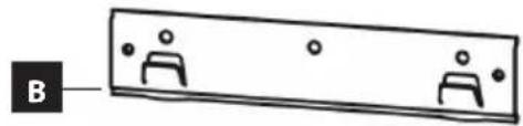
natural_image
Simple diagram of a rectangular object with three identical figures and dots, labeled 'B' at the bottom (no text or symbols on the object itself)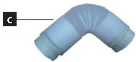
natural_image
3D rendering of a blue curved pipe fitting with flanged ends (no text or symbols)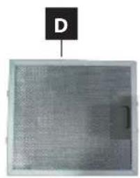
natural_image
Metal mesh panel with a labeled point 'D' above it (no other text or symbols)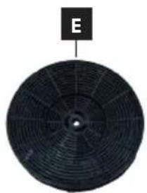
natural_image
Circular black fan or petal-like object with radial lines, labeled 'E' at top (no other text or symbols)POPIS OVLÁDACÍHO PANELU
natural_image
Pure technical diagram of a mechanical component with no text or symbols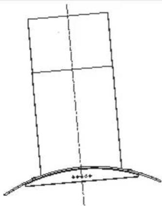
natural_image
Simple line drawing of a curved structure with dashed centerline (no text or symbols)SPRÁVNĚ ŠPATNĚ
Obr. 6
natural_image
Line drawing of a 3D cabinet with an inset showing a close-up view of the front panel (no text or symbols)Obr. 7
natural_image
Technical line drawing of a mechanical device with a magnified inset showing internal components (no text or symbols)Demontáž
natural_image
Symbol of a trash bin crossed with a diagonal line, no text or numbers present
natural_image
Simple line drawing of a rectangular device with internal components and a labeled section A (no text or symbols on the device itself)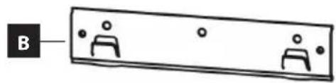
natural_image
Simple line drawing of a rectangular object with two identical human figures and dots, connected by a black arrow labeled 'B' (no text or symbols on the object itself)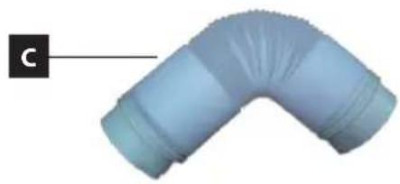
natural_image
3D rendered image of a curved pipe fitting with a label 'C' pointing to it (no text or symbols on the object itself)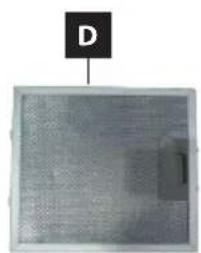
natural_image
Close-up of a perforated metal panel with a labeled point D above it (no text or symbols on the panel itself)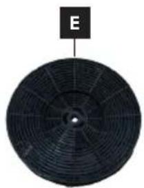
natural_image
Circular black fan or blade with radial blades, labeled 'E' at top (no other text or symbols)POPIS OVLÁDACIEHO PANELU
1 Tlačidlo zapnutia/vypnutia osvetlenia
2 Tlačidlo mínus (-)
3 Displej
4 Tlačidlo plus (+)
5 Tlačidlo zapnutia/vypnutia prístroja
POPIS JEDNOTLIVÝCH TLAČIDIEL OVLÁDACIEHO PANELU
Tlačidlo zapnutia/vypnutia osvetlenia
natural_image
Pure technical diagram showing a vertical structure with a base and curved base, no text or symbols present.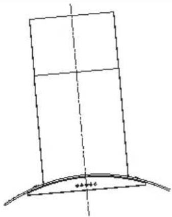
natural_image
Simple line drawing of a curved structure with a vertical plane and a base, no text or symbols present.SPRÁVNE NESPRÁVNE
Obr. 6
natural_image
Technical line drawing of a 3D cabinet with an inset showing a close-up view of the front panel (no text or symbols present)Obr. 7
natural_image
Technical line drawing of a mechanical assembly with a magnified inset showing a component detail (no text or symbols)Demontáž
natural_image
Symbol of a trash bin crossed with a diagonal line, no text or numbers present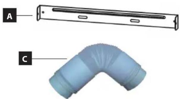
natural_image
Technical diagram of a flexible hose component with labeled parts A and C (no text or symbols on the diagram itself)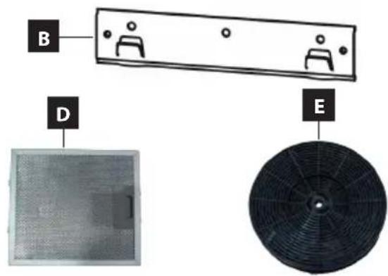
OPIS PANELU STEROWANIA
OPIS POSZCZEGÓLNYCH PRZYCISKÓW NA PANELU STEROWANIA
natural_image
Pure technical diagram showing a vertical structure with a curved base and dashed centerline (no text or symbols)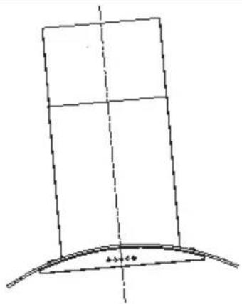
natural_image
Simple line drawing of a geometric shape with a vertical axis and curved base (no text or symbols)PRAWIDŁOWO NIEPRAWIDŁOWO
Rys. 6
natural_image
Technical line drawing of a 3D cabinet with an inset showing a close-up view of the front panel (no text or symbols present)Rys. 7
natural_image
Technical line drawing of a mechanical assembly with a magnified inset showing internal components (no text or symbols)Demontaż
natural_image
Symbol of a trash bin crossed with no text or numbers, representing waste sorting or disposal (no text present)
natural_image
Simple line drawing of a rectangular object with internal slots and a labeled section A (no text or symbols on the object itself)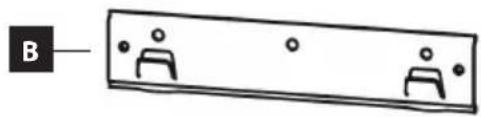
natural_image
3D rendered image of a curved pipe fitting with flanged ends, labeled 'C' in the corner (no text or symbols on the object itself)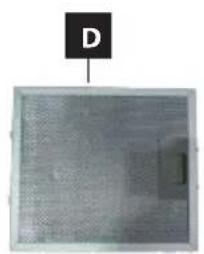
natural_image
Metal mesh panel with a labeled point D pointing to it (no text or symbols on the panel itself)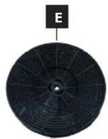
natural_image
Circular black fan or petal-like object with radial lines, labeled 'E' at top (no other text or symbols)VADĪBAS PANELA APRAKSTS
ATSEVIŠKU VADĪBAS PANELA TAUSTIŅU APRAKSTS
natural_image
Pure technical diagram showing a vertical structure with a curved base and dashed centerline (no text or symbols)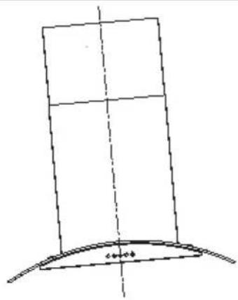
natural_image
Simple line drawing of a curved structure with dashed centerline (no text or symbols)PAREIZI NEPAREIZI
- att.
natural_image
Technical line drawing of a 3D cabinet with an inset showing a close-up view of the front panel (no text or symbols present)- att.
natural_image
Technical line drawing of a mechanical assembly with a dashed circular inset showing a component (no text or symbols)Demontāža
TRAUCĚJUMU NOVĚRŠANA
natural_image
Symbol of a trash bin crossed with no text or numbers, representing waste sorting or disposal (no text present)Thank you for purchasing the Concept product. We want you to be satisfied with everything we make every day you use it.
Please read the instructions carefully before initial use. You should retain them for future reference. Ensure that anyone using this product is familiarized with the instructions.
TABLE OF CONTENTS
Technical specifications
Important safety information
Product description
Control panel description
Description of individual buttons of the control panel
User manual
Cleaning and maintenance
Installation of the appliance
Troubleshooting
Environmental protection
TECHNICAL SPECIFICATIONS
| Technical specifications | |
| Voltage 220-240 V, 50/60 Hz | |
| Total power input 213 W | |
| Motor power input 210 W | |
| Type Chimney type | |
| Assembly Wall mounting | |
| Height 460–830 mm | |
| Width 600 mm | |
| Depth 500 mm | |
| Diameter of flexible outlet duct 150 mm | |
| Extracted air output stages 3 | |
| Capacity of extracted air 612 m | ^3/h |
| Fat filters 1 | |
| Required number of carbon filters for recirculation 2 | |
| Mode | Ventilation/recirculation |
| LED lamp | 2 x 1.5 W |
| Weight | 13.2 kg |
| Noise level of ventilation/recirculation | ≤66 dB (A) |
The manufacturer reserves the right to make potential technical changes, typographical errors and any differences in the representation without prior notice.
IMPORTANT SAFETY INFORMATION
Upon delivery of fume hood
- Immediately after delivery, check the package for any damage during shipping.
- Caution! Caution! Some edges of this appliance that are hidden after installation are sharp! Be careful not to get cut when handling an uninstalled unit.
- Do not install the appliance if it has been damaged. Contact the store where you purchased it immediately.
- Remove all the packaging and marketing materials before first use.
- Keep the packaging materials away from children or dispose of them properly.
During installation
- Do not use the appliance in any way other than as described in this manual.
-
Only use it as a household appliance and for removal of fumes arising from cooking of food or for recirculation and absorption of smells arising from cooking of food.
• This appliance can be used in households and similar places like: -
Kitchen cabinets in shops, offices and other workplaces.
- Appliances used in agriculture.
- Appliances used by guests in hotels and other areas in a hotel environment.
-
Appliances used in a Bed and Breakfast environment.
-
Do not touch the appliance with wet hands.
- Do not allow children or unauthorized people to handle the appliance, use it out of their reach.
• Children should not play with the appliance. - Pay extra attention if the appliance is used near children.
- Do not allow the appliance to be used as a toy.
- This appliance can be used by children aged 8 years and over. Persons with reduced physical, sensory or mental capabilities, or lack of experience and knowledge, should be supervised or familiarized with the instructions for use of the appliance in a safe way and have been made aware of the risks involved.
-
If a malfunction occurs, turn off the appliance and unplug it from the wall outlet.
-
When disconnecting the unit from the wall outlet, never pull the power cord, grasp the plug end and disconnect it by removing it from the receptacle.
- Do not immerse the power cord or the plug in water or any other liquid.
- Check the appliance and the power cord for damage regularly.
- Do not switch on the appliance if it has been damaged.
- Unless the appliance is in operation, ensure that all its controls are switched off.
- Do not manipulate with an open flame (e.g. singeing) under the appliance. If you remove a cooking vessel from a gas burner, reduce its flame to minimum or turn it off!
- Caution! Risk of fire! Care must be taken to ensure that the diameter of the gas burners on the gas cooker or the cooking plate corresponds to that of cooking utensils used. If cooking vessels with a diameter lower than recommended are used, the flame could start to burn around the cooking vessel resulting in a risk of melting plastic handles.
- While deep frying or frying of food, observe this food all the time. In the case of oil overheating, there is a risk of fire!
- Ensure that the flames do not get too close to the appliance.
- Observe intervals for replacement and cleaning of filters (at least every 2-3 months). Failure to observe these requirements results in a risk of fire due to fat accumulating in the filters!
- All the respective current standards and official regulations must be observed relating to the removal of the extracted air.
- A ventilation duct diameter for the removal of the extracted air should be approximately the same or larger than that of the hood's flexible outlet duct.
- Extracted air should not be led to a chimney intended for discharge of flue gases and combustion products or a shaft serving for ventilation of rooms where fireplaces are situated.
- When the appliance and fireplaces are in operation simultaneously, vacuum in the room should not be higher than 4 Pa (0.04 mbar).
- Do not use any accessories other than those recommended by the manufacturer.
- Do not use accessories with damaged surface treatment or if it has been worn out or has other defects.
- Do not use any corrosive cleaning agents for cleaning. Maintenance and cleaning on a regular basis extend the lifetime of the appliance.
• Children should not clean and maintain the appliance unless they are at least 8 years old and under supervision.
Possible defects
- Only qualified service technicians should repair or perform maintenance to this appliance.
- During the repairs the appliance must be disconnected from the power. Switch off the circuit breaker or remove the plug from the wall outlet.
- When disconnecting the unit from the wall outlet, never pull the power cord, grasp the plug end and disconnect it by removing it from the receptacle.
- If the power cord is damaged, contact the authorised service centre.
If you fail to follow these instructions, any possible repair cannot be recognized as a warranty repair.
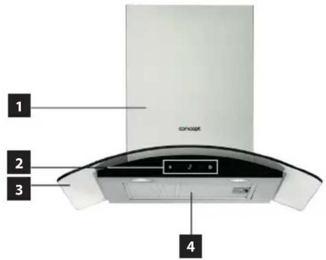
PRODUCT DESCRIPTION
1 Lower chimney cover
2 Control panel
3 Appliance body
4 Fat filter
Accessories
A Bracket for upper and lower chimney cover
B Bracket for appliance
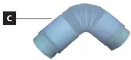
C Flexible outlet duct
D Metal fat filter
E Carbon filter (to be purchased)

natural_image
Simple line drawing of a rectangular device with internal components, labeled 'A' (no text or symbols on the device itself)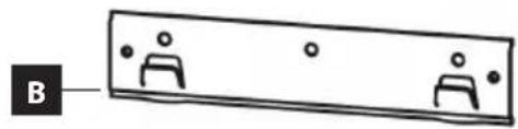
natural_image
Simple line drawing of a rectangular object with two human figures inside, labeled 'B' on the left (no text or symbols on the object itself)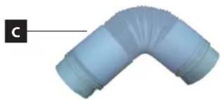
natural_image
3D rendering of a blue curved pipe fitting with flanged ends, labeled 'C' in the corner (no text or symbols on the object itself)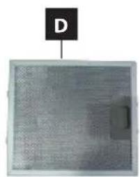
natural_image
Close-up of a textured surface with a small rectangular feature and a labeled point 'D' above (no readable text or symbols)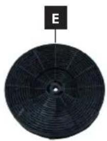
natural_image
Circular black fan or blade with radial blades, labeled 'E' at top (no other text or symbols)CONTROL PANEL DESCRIPTION
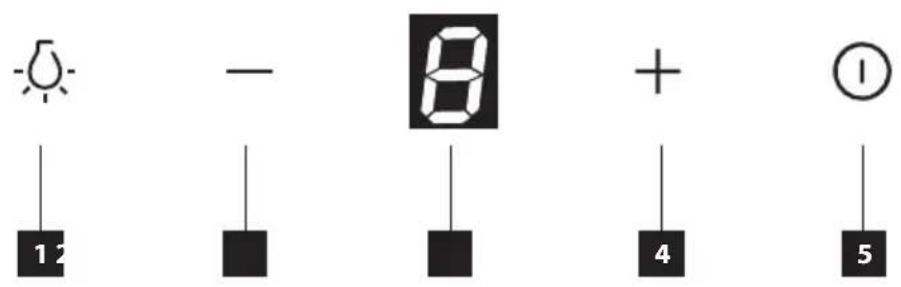
1 Lighting On/Off button
2 Minus (-) button
3 Display
4 Plus (+) button
5 Appliance On/Off button
DESCRIPTION OF CONTROL PANEL BUTTONS
Lighting On/Off button
- Push the button to switch on/off the appliance lighting.
Minus (-) button
- Push the button to decrease extracted air exhaust output.
- When pushed, the button illuminates and the display shows the output value (1-3).
- If the output value is 1 and the minus (-) button is pushed, only an audible signal will sound and the display will show the lowest output value (1).
- You can decrease the extracted air output only when the appliance is switched on.
Display
• The display shows the extracted air exhaust output.
Plus (+) button
- Push the button to increase extracted air exhaust output.
- When pushed, the button illuminates and the display shows the output value (1-3).
- If the output value is 3 and the plus (+) button is pushed, only an audible signal will sound and the display will show the highest output value (3).
- You can increase the extracted air output only when the appliance is switched on.
Appliance On/Off button
- Push the button to switch on/off the appliance.
- When pushed, the button illuminates.
-
Upon switching the appliance on, the extracted air output is set to the lowest output value (1). This value is shown on the display.
-
Whenever the appliance is switched on, the extracted air output shall always be set to the lowest output value (1).
- If you push the On/Off button when the appliance is switched on, the extracted air output shall decrease to the lowest output value (1) and the delayed switching-off shall take place after 3 minutes. The lowest output value (1) will start flashing on the display.
- The preset time for the delayed switching-off is fixed and cannot be changed.
- During the delayed switching-off, you can switch off the appliance by pushing the On/Off button.
- To switch off the appliance completely, push the On/Off button twice.
USER'S MANUAL
Before first use
Before first use you should wipe the outside and inside of the appliance with a damp cloth for hygiene reasons.
Ventilation mode
The extracted air is discharged through the flexible outlet duct to the ventilation shaft out of the room. If the appliance is equipped with a carbon filter, remove it (see chapter Cleaning and maintenance).
- Push button (5) to switch on the appliance.
- Using buttons (2) and (4) select the required value of the extracted air exhaust output.
- The display shows the output value (1-3).
- Push button (5) twice to switch the appliance off.
Recirculation mode
If there is no possibility of discharging the extracted air out of the room, you can use the recirculation mode. In this case, the extracted air is filtered through the metal fat filters and the carbon filter. An active carbon in this filter absorbs the smell. Air, free from the smell, flows back into the room through openings situated in the upper chimney cover. When the recirculation mode is used, it is necessary to purchase and install the appropriate carbon filters (see chapter Cleaning and maintenance).
- Push button (5) to switch on the appliance.
- Using buttons (2) and (4) select the required value of the extracted air exhaust output.
- The display shows the output value (1-3).
- Push button (5) twice to switch the appliance off.
Note:
When the recirculation mode is used (carbon filter installed), the extracted air output can drop.
CLEANING AND MAINTENANCE
- Disconnect the power cord from the wall outlet or switch off the circuit breaker of the appliance before cleaning and maintenance.
• To clean the appliance outside, use a damp cloth, a soft brush or a fine sponge, and then wipe it dry. - Do not use coarse abrasive cleaning agents or sharp metal scrapers for cleaning of the appliance as this could result in surface scoring.
- Do not use steam jets to clean the appliance!
- Never leave aggressive or acidic substances (lemon juice, vinegar) on enamelled or stainless parts of the appliance.
Cleaning and replacement of filters
Metal fat filters
When the appliance is in common use, the metal fat filters should be checked or cleaned every month. In case of more frequent frying or deep frying, shorten this interval.
Do not use the appliance without the metal fat filters properly installed!
-
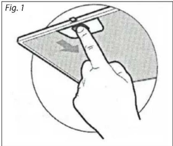
Remove the metal filter according to Fig. 1.
-
We recommend to soak the metal filters in warm water with a detergent, then to clean with a soft brush, rinse with clean water and allow to dry. The filters are also dishwasher safe using a program below 60 °C. In this case, it is necessary to avoid the use of aggressive detergents –the aluminum filters can blacken under the influence of the chemical reaction.
-
Reinstall dried out filters.
natural_image
Illustration of a hand using a tool to press or interact with a device, showing a finger pointing at the screen (no text or symbols present)Carbon filter (to be purchased)
This filter is only used for the recirculation mode.
The filter contains an active carbon absorbing the smell being discharged. The active carbon will be saturated after some time, hence the absorption capacity will be shortened. This filter cannot be washed or cleaned in any other way.
When the appliance is in common use, the carbon filter should be replaced every 2-3 months. In case of more frequent frying or deep frying, shorten this interval.
-
Remove the metal filters as shown in Fig. 1.
-
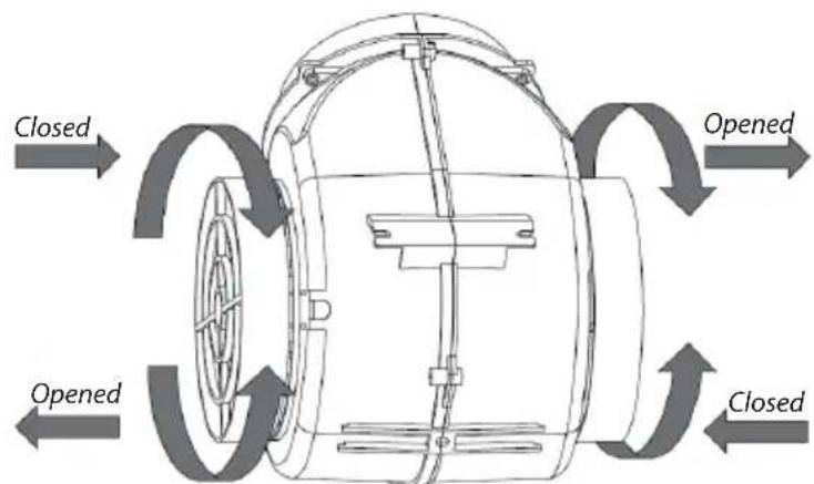
The carbon filters are situated on both sides of the motor. Turn the filters, until they are secured (see Fig. 2).
-
To replace the carbon filter, proceed in reverse order.
Fig. 2
INSTALLATION OF THE APPLIANCE
Caution!
Risk of electric shock! Before installation, disconnect the power cord from the wall outlet. Otherwise there is a risk of death or electric shock.
- Defects caused by improper installation are not covered by the warranty.
• Installation is the responsibility of the customer not the manufacturer.
- The manufacturer bears no responsibility for damage caused to people, animals or property due to incorrect installation.
- All guards must be placed firmly in their appropriate place in a way they cannot be removed without using special tools.
• Install the appliance at least 650 mm above the electric and gas cookers or electric and gas hobs.
- Extracted air should not be led to a chimney intended for discharge of flue gases and combustion products or a shaft serving for ventilation of rooms where fireplaces are situated.
- Any bend of the ventilation pipe should be ≥ 120^ .
• The room must be well ventilated during cooking.
Connection to the mains
- Make sure the mains voltage and current protection correspond to the values on the rating plate of the appliance.
- Only use grounded sockets.
- Do not use multiple sockets, plugs and extension cords.
- The plug of the power cord on the appliance must be freely accessible even after the installation.
• Changes in a connection may only be performed by a qualified professional.
- Electrical safety of the appliance can be guaranteed only if the protective terminal of the appliance is connected to the protective conductor of the mains.
- The manufacturer bears no responsibility for damage to persons or property as a result of missing or bad protective connection.
When installing the appliance, follow these steps:
-
Remove all the packaging and marketing materials before first use.
-
Mark the required installation height 650 mm on the wall behind the cooker or the cooking plate (Fig. 3).
-
Draw a vertical line to mark the centre of the cooking plate (of the cooker).
-
Drill the holes at an appropriate height and attach the hood holder according to Fig. 4 (Step A).
-
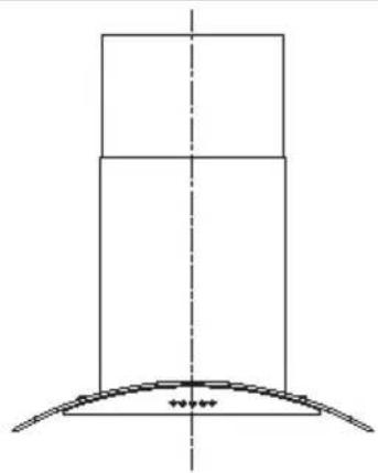
Make sure that the bracket is in the horizontal position in order to prevent grease (fat) from being accumulated on one side after the hood has been hung (Fig. 5).
-
Hang the fume hood on the mounted bracket and attach the lower chimney cover.
-
Mark the points on the wall and drill the holes for mounting the lower chimney part holder as shown in Fig. 4 (Step B).
-
Attach the flexible exhaust pipe to the exhaust opening. Use a reducer fitting 150/120 mm in diameter, if required. Insert the second part of the flexible duct in the opening prepared in the wall.
-
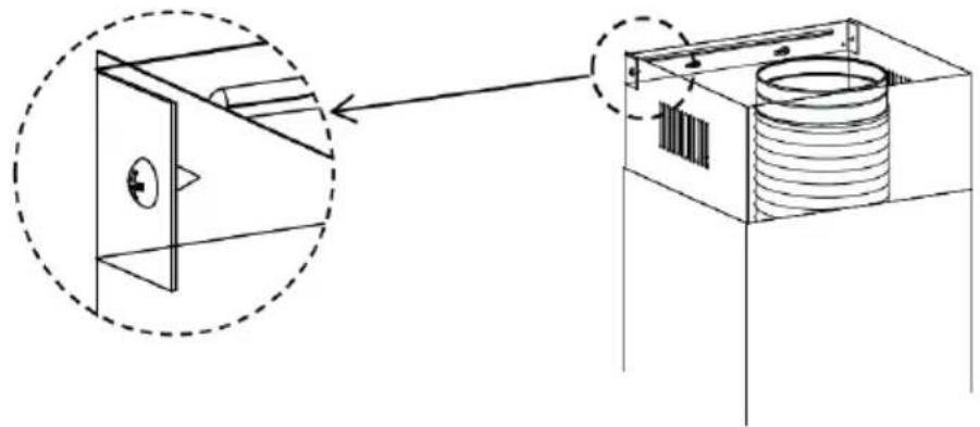
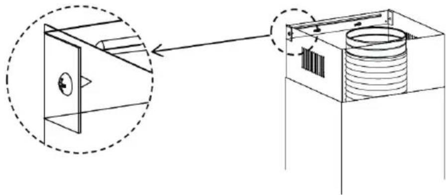
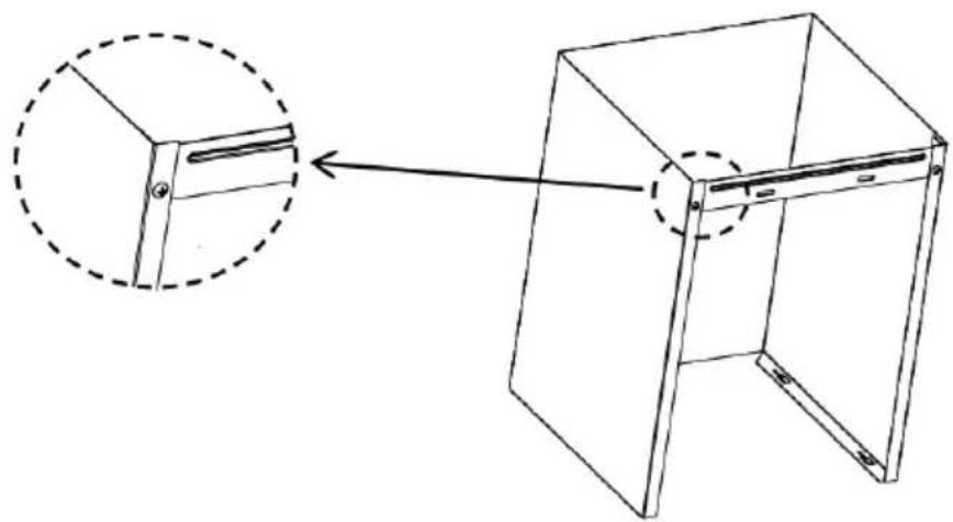
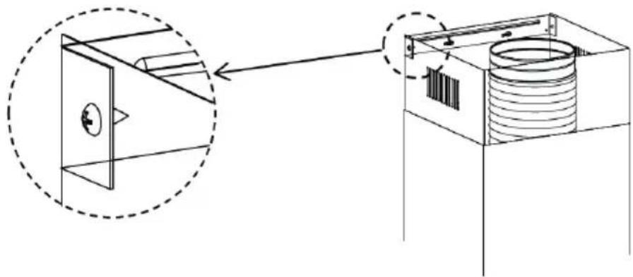
Place the lower part as well as the upper part of the chimney on the hood hung (Fig. 7). Lift the upper part up to the required height and mark holes on the wall for attachment of the upper chimney part bracket. Subsequently remove the lower as well as the upper chimney part.
-
Drill holes and attach the upper chimney part bracket (step C).
-
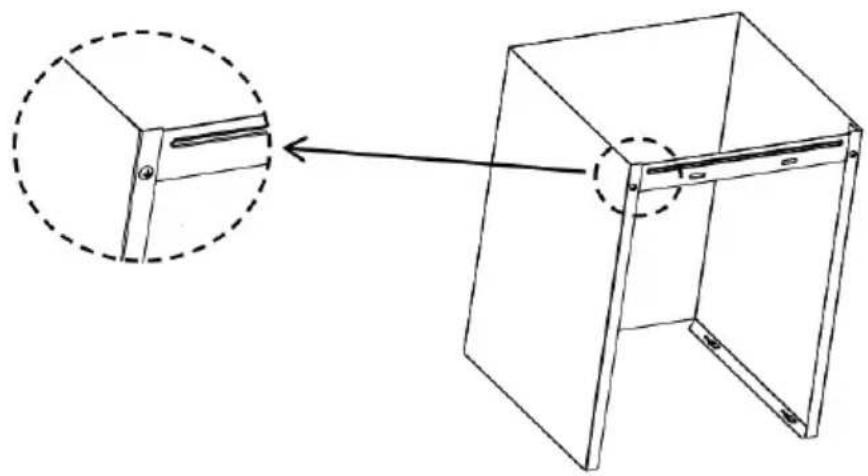
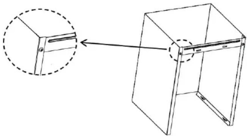
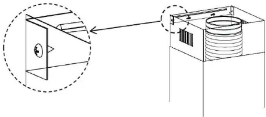
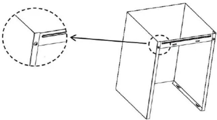
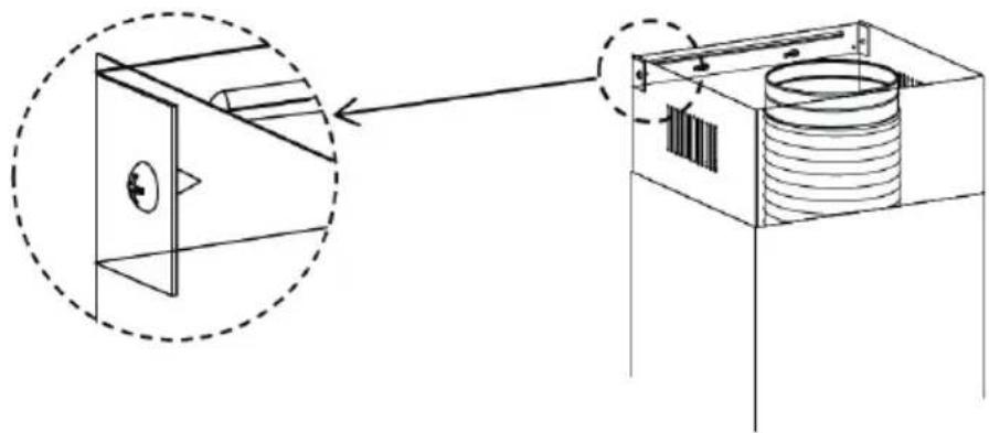
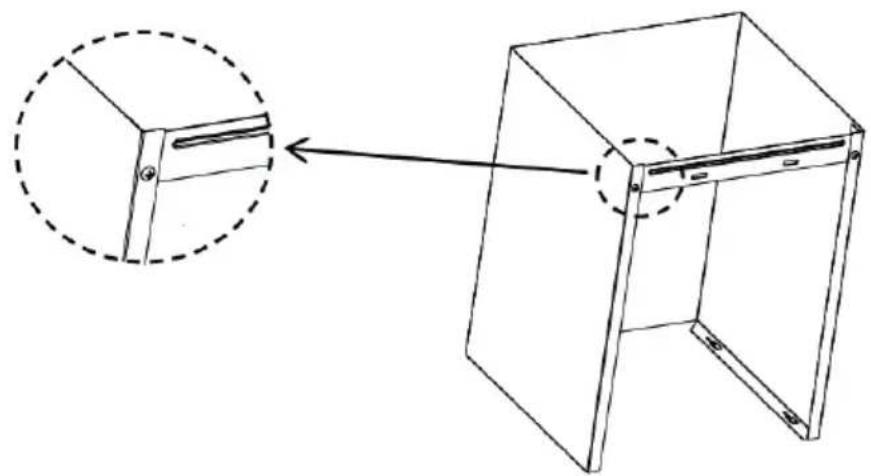
Place the lower as well as the upper chimney part. Attach the lower chimney part to the lower chimney part holder as shown in Fig. 6. Lift the upper part up to the required height and attach the upper chimney part to the upper chimney part holder as shown in Fig. 7.
-
Plug the power cord into the wall outlet.
Fig. 3
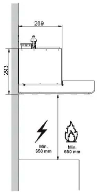
Fig. 4
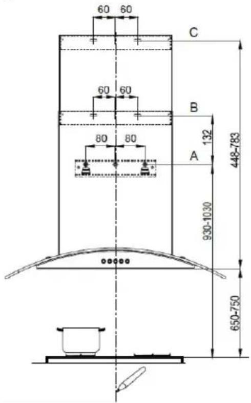
Fig. 5
natural_image
Pure technical diagram of a mechanical component with no text or symbols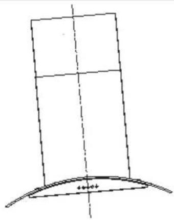
natural_image
Simple line drawing of a curved structure with dashed centerline (no text or symbols)CORRECT INCORRECT
Fig. 6
natural_image
Technical line drawing of a 3D cabinet with an inset showing a close-up view of the front panel (no text or symbols present)Fig. 7
natural_image
Technical line drawing of a mechanical assembly with a dashed circular inset showing a component (no text or symbols)Disassembling
If you disassemble the appliance, it is important to follow the steps in the correct order:
- First, unplug the power cord from the mains (pull the plug out or switch off the circuit breaker).
- Subsequently disassemble individual parts of the hood in reverse order of the appliance installation.
TROUBLESHOOTING
| Defect description Possible cause Solution | ||
| Lamps illuminate but the motor stands idle | The motor blades are blocked. Contact the service centre. | |
| The motor or its essential parts are damaged. | Contact the service centre. | |
| The plug inserted incorrectly or insufficiently in the wall outlet. | Check connection of the plug. | |
| The wall outlet is not energized. | Check that the wall outlet is energized, e.g. by connecting another appliance. | |
| Lamps do not illuminate and the motor stands idle | The plug inserted incorrectly or insufficiently in the wall outlet. | Check connection of the plug. |
| The wall outlet is not energized. | Check that the wall outlet is energized, e.g. by connecting another appliance. | |
| Fat drops from the metal fat filters | Heavily fouled filters.Risk of fire! | Immediately clean or replace the metal fat filters. |
| The appliance vibrates when the appliance is on | The motor blades are damaged. Contact the service centre. | |
| The motor is not fixed fast. | Contact the service centre or fix the motor fast. | |
| The hood is not fixed fast. Fix the hood fast. | ||
| Insufficient exhaust of the extracted air | Distance between the hood and the cooking plate is too long. | Reduce distance between the hood and the cooking plate. |
| Strong draught, too many doors or windows opened. | Close some doors or windows. | |
| The motor stopped working | The thermal overload protection against the motor overheating triggered. | Improve the room ventilation, open doors or windows or check distance between the hood and the cooking plate. If required, increase distance between the hood and the cooking plate. |
| The hood is not levelled | The hood bracket is not levelled or the bracket screws are not tightened firmly. | Check the bracket for being levelled or tighten holding screws and level the hood. |
SERVICE CENTRE
Extensive maintenance or repair, which requires access to internal parts of the product, has to be performed by a qualified specialist or the service centre.
ENVIRONMENTAL PROTECTION
- Prefer recycling of packaging materials and old appliances.
- Packaging materials may be disposed of as sorted waste.
- Dispose the plastic bags made of polyethylene (PE) of as sorted waste.
Recycling of the appliance at the end of its lifespan:
natural_image
Symbol of a trash bin crossed with no visible text or labelsThis appliance is labelled in accordance with European Directive 2012/19/EU concerning used electrical and electronic appliances (waste electrical and electronic equipment - WEEE). The symbol on the product or its packaging indicates that this product may not be treated as household waste. It is necessary to take it to a container park for the recycling of electrical and electronic equipment. By ensuring the correct disposal of this appliance you will help prevent potential negative consequences to the environment and human health, which could otherwise result from inappropriate disposal of this product. Disposal must be performed in accordance to the regulations for waste disposal. For more detailed information about recycling of this appliance see the authorized local office or service for household waste disposal or the shop, where you purchased the appliance.
concept
CONCEPT POLSKA sp. z o.o.
- PODĚKOVÁNÍ
- POPIS OVLÁDACÍHO PANELU
- Demontáž
- POPIS OVLÁDACIEHO PANELU
- POPIS JEDNOTLIVÝCH TLAČIDIEL OVLÁDACIEHO PANELU
- Tlačidlo zapnutia/vypnutia osvetlenia
- OPIS PANELU STEROWANIA
- OPIS POSZCZEGÓLNYCH PRZYCISKÓW NA PANELU STEROWANIA
- Demontaż
- VADĪBAS PANELA APRAKSTS
- ATSEVIŠKU VADĪBAS PANELA TAUSTIŅU APRAKSTS
- Demontāža
- TABLE OF CONTENTS
- TECHNICAL SPECIFICATIONS
- IMPORTANT SAFETY INFORMATION
- Upon delivery of fume hood
- During installation
- Possible defects
- PRODUCT DESCRIPTION
- Accessories
- CONTROL PANEL DESCRIPTION
- DESCRIPTION OF CONTROL PANEL BUTTONS
- Lighting On/Off button
- Minus (-) button
- Display
- Plus (+) button
- Appliance On/Off button
- USER'S MANUAL
- Before first use
- Ventilation mode
- Recirculation mode
- Note:
- CLEANING AND MAINTENANCE
- Cleaning and replacement of filters
- Metal fat filters
- Carbon filter (to be purchased)
- INSTALLATION OF THE APPLIANCE
- Caution!
- Connection to the mains
- When installing the appliance, follow these steps:
- Disassembling
- SERVICE CENTRE
- ENVIRONMENTAL PROTECTION
- Recycling of the appliance at the end of its lifespan:
- CONCEPT POLSKA sp. z o.o.
Brand : Concept
Model : OPK2660
Category : Range hood