
OSS522 - Range hood AMICA - Free user manual and instructions
Find the device manual for free OSS522 AMICA in PDF.


| Product Type | Range Hood |
| Brand | Amica |
| Model | OSS522 |
| Installation Type | Built-in / Under Cabinet |
| Width (mm) | 600 |
| Depth (mm) | 500 |
| Height (mm) | 130-150 (adjustable) |
| Net Weight (kg) | 12 |
| Power Supply | 220-240 V ~ 50 Hz |
| Motor Power (W) | 180 |
| Extraction Rate (m³/h) | 550 |
| Noise Level (dB) | 58 |
| Energy Class | D |
| Control Type | Slider |
| Number of Speeds | 3 |
| Lighting | 2 x 40 W halogen |
| Filter Type | Aluminum Grease Filter (washable) |
| Optional Accessories | Charcoal filter for recirculation |
| Duct Diameter (mm) | 150 |
| Air Outlet Position | Top |
| Maintenance | Monthly cleaning of grease filter; replace charcoal filter every 3-6 months |
| Safety Features | Thermal motor protection |
| Included in the Box | Hood, flue pipe, fixings, manual |
| Repairability Index | 5.2/10 (estimated) |
Frequently Asked Questions - OSS522 AMICA
User questions about OSS522 AMICA
0 question about this device. Answer the ones you know or ask your own.
Ask a new question about this device
Download the instructions for your Range hood in PDF format for free! Find your manual OSS522 - AMICA and take your electronic device back in hand. On this page are published all the documents necessary for the use of your device. OSS522 by AMICA.
USER MANUAL OSS522 AMICA
You are now a user of a kitchen extractor hood of OSC 6562W, OSC 5562W, OSC 6552 I, OSC 5552I type. This hood has been designed and manufactured specially with a view to satisfying your expectations and it will certainly constitute a fitting element of a modern kitchen. The modern structural solutions and the newest technologies used in production of this hood guarantee its high effectiveness and good appearance. Please read these instructions carefully before installing the hood. They will help you avoid mistakes during installation and operation of the hood.
We wish you a lot of satisfaction from choosing our kitchen extractor hood.

NOTE: The manufacturer will accept no responsibility for any damage due to installation or operation not conforming to these instructions
PL
I CHARAKTERYSTYKA 7
II WYPOSAŻENIE 7
IV WARUNKI EKSPLOATACJI 8
V MONTAŽ 9
VI OBSŁUGA I KONSERWACJA 10
VII GWARANCJA I OBSŁUGA POSPRZEDAŻNA 12
CZ
I CHARAKTERYSTIKA 13
II VYBAVENÍ 13
IV BEZPEČNOSTNÍ POKYNY 14
V MONTAŻ 15
VI OBSLUHA A ÚDRŽBA 16
VII ZÁRUKA A POPRODEJNÍ SERVIS 18
SK
I CHARAKTERISTIKA 19
II VYBAVENIE 19
IV EXPLOATAČNÉ PODMIENKY 20
V MONTÁŽ 21
VI OBSLUHA A ÚDRŽBA 22
VII ZÁRUKA A POPREDAJNA OBSLUHA. 24
DE
I CHARAKTERISTIK 25
II AUSSTATTUNG 25
natural_image
Close-up of a hand holding a black plastic clip against a red background (no text or symbols visible)
natural_image
Hand placing a green paper envelope into a blue sheet, against a blurred orange background (no text or symbols visible)
natural_image
Close-up of a hand holding a dark circular object with internal lines, against a blurred orange background (no text or symbols visible)
natural_image
Close-up of a hand pointing at a black cylindrical device with a vertical slot, placed on a wooden surface (no visible text or symbols)
natural_image
Close-up of a blue electric drill bit with a metal screw, no visible text or symbols
natural_image
Hand holding a wooden hammer with a white tool above it, against a plain wall (no text or symbols visible)
natural_image
Close-up of a hand holding a small metallic tool, possibly a screw or tool, with no visible text or symbols.14
natural_image
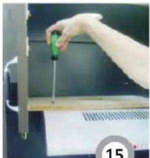
Hand using a screwdriver to press or install a mechanical component (no visible text or symbols)15
natural_image
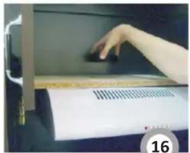
Hand pressing down on a device with a grid of small components (no visible text or symbols)16
natural_image
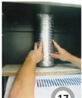
Person handling a coiled metal object on a surface, no visible text or symbols17

natural_image
Close-up of a metallic U-shaped pipe with ribbed texture (no text or symbols visible)18

natural_image
Close-up of a coiled, worm-like structure with red cross symbol (no text or symbols on the structure itself)natural_image
Simple line drawing of a recycling symbol (three chasing arrows), no text or labels present.ZALECENIA:
natural_image
Simple line drawing of a trash bin with crossed lines indicating no waste or discharge (no text or symbols)natural_image
Simple line drawing of a recycling symbol (three chasing arrows), no text or labels present.natural_image
Symbol of a trash bin crossed with a diagonal line and a horizontal bar below (no text or labels)natural_image
Simple line drawing of a three chasing recycling symbol (no text or labels)POKYNY:
natural_image
Simple line drawing of a recycling symbol (three chasing arrows), no text or labels present.This kitchen extractor hood was designed to remove or neutralize kitchen fumes. It has to be installed permanently over a gas or electric cooker. It requires installation of a conduit discharging used air to the outside if working in fume removal mode. The conduit (a pipe ∅120 mm) shall not be longer than 4-5 m. The hood can operate as an odour absorber after installation of an active carbon filter. In such case a conduit discharging used air to the outside is not necessary. The kitchen hood is an electrical appliance manufactured according to class II of fire protection, equipped with a permanent supply cord and plug. It has its own lighting and an exhaust fan which can be set to one of three rotational speeds.
II COMPONENTS
kitchen hood consists of the following elements (Fig. 1):
- Control Panel
- Aluminium grease filters
- Lighting assembly
- Appliance body
-
Glass panel
-
The kitchen hood was designed for removal of kitchen fumes to the outside. It should be connected to an appropriate ventilation duct (do not connect the hood to any chimney, smoke or flue-gas ducts which are in use).
- The safe distance between a cooker and the kitchen hood should be at least 650 mm. If cooker manual including other distance, this should be taken into account.
- Do not leave open flame under the hood. When removing pots from the burners set the flame to its minimum level.
- Any food cooked in fat shall be constantly monitored, since overheated fat can ignite very easily.
- The textile grease filter should be replaced, and the aluminium filter should be cleaned at least every 2 months in connection with the existing fire danger (saturated fat is very flammable).
- Pull the plug of the power cord from a wall socket before any filter cleaning or repair operation.
- If any other non-electric devices are used in the same room as the hood (e.g. liquid fuel ovens, flow-through or volumetric water heaters), it is necessary to provide appropriate ventilation (air supply). Safe operation is possible when during simultaneous operation of the hood and combustion devices dependent on air supply the negative pressure of not more than 0.004 milibar is maintained at the location of these devices inside the room (this point does not apply when the hood is used as an odour absorber).
- When connecting to 240V power supply network use an electric socket in working order.
- do not lean against the hood
- Hood should be cleaned once per month - see point „Cleaning” in this manual.
- If the power wire gets broken, it should be replaced with a new one in a specialist repair shop.
This appliance is designed for household use only. The manufacturer reserves the right to introduce changes which do not affect the operation of the appliance.
UNPACKING
The device was protected against damage for the time of transport. After unpacking, please remove the elements of packaging in an environment-friendly way. All materials used for packaging are environment friendly, they can be 100% recycled and they have been marked with appropriate symbols.

natural_image
Simple line drawing of a recycling symbol (three chasing arrows), no text or labels present.Warning! The packaging materials (polyethylene bags, small pieces of foamed polystyrene etc.) should be kept away from children while unpacking.
RECOMMENDATIONS
- before you connect the hood to the power supply and check whether it works properly, you will always need to control if the wire has been properly installed and if it has NOT been pinned down by the hood while it was being mounted.
- This appliance is not intended for use by persons (including children) with limited physical or mental capabilities and persons who lack experience or familiarity with the appliance.
Do not allow unattended children to use the appliance. Do not allow them to play with the appliance.
Install the cooker hood under a wall cabinet:
- Drill 4 holes in the wall cabinet that match the spacing of holes in the hood.
- Make a hole (over 120 mm in diameter) to fit the extraction duct or the plug. The hole must be located directly above the cooker hood air outlet.
- Using the supplied four mounting screws (M4X30) attach the hood to the wall cabinet (Fig. 15).
- Depending on the mode of operation (extraction or odour absorber - for see details see the manual) fit the plug (Fig. 10 and 16) or the exhaust duct flange (Fig. 11 and 17).
- Connect the hood to power and make sure it operates correctly.
Install the cooker hood on the wall:
- Drill 2 holes in the wall that match the spacing of holes in the hood (Fig. 12). Put plastic wall plugs in the holes (Fig. 13) and screw in hooks (Fig. 14).
- Hang the hood on the wall, connect it to power and make sure it operates correctly.
Connecting to the power network and operation check
After connecting the device to the power supply network (in accordance with the requirements defined above) it is necessary to check operation of the motor and lighting of the hood.
Setting the operation mode of the kitchen extractor hood
Setting the air extractor mode of operation of the hood
When cooker hood operates in extraction mode, air is discharged outside through an extraction duct. The cooker hood is connected to the air outlet opening using a rigid or flexible extraction duct with a diameter of 120 mm, and the appropriate clamps, which must be purchased at a hardware store. Connect one end of the duct to the flange (Fig. 17), and the other to the air outlet hole. Proper duct routing is shown in Fig. 18 Also, make sure that one of the inserts is installed (install a bigger one for the extraction mode (Fig. 9)). To install or remove the insert, undo the screw and slide the insert along the rails (Fig. 4b).
A qualified installer should be commissioned to make the connection.
Setting the odour absorber mode of operation of the hood
In this setting the air is filtered and returned back to the room through openings located in the upper part of the body of the hood. Install activated charcoal filter in this setting (see the manual for details on installation). Also, make sure that one of the inserts is installed (install a smaller one for the extraction mode (Fig. 8)). To install or remove the insert, undo the screw and slide the insert along the rails (Fig. 41). In addition, air outlet hole should be plugged (Fig. 4c).
Fan speeds
The lowest and medium speeds should be used under normal conditions and with low concentration of fumes. The top speed should be used in case of high concentration of kitchen fumes, e.g. during frying or grilling.
1. Operational safety.
All safety instructions included in chapter IV must be observed. Textile grease filters and carbon filters should be replaced and aluminium filter should be cleaned according to manufacturer's instructions, or more frequently in periods of intensive use (more than 4 hours a day). If a gas cooker is used it is forbidden to leave uncovered flame. When removing pots from gas burners set the flame to its minimum level. Always make sure that flame does not extend outside the pot. Such a situation causes undesired energy losses and dangerous heat build-ups. The hood should not be used for other purposes than those for which it was designed.
2. Operation:
2.1 Control panel
Operation of the hood can be controlled by means of switches (Fig. 5):
- Turnlight on / off
- Level 1 fan speed
- Level2 fan speed
- Level 3 fan speed
- Poffer on / off
3. Maintenance.
Regular maintenance and cleaning of the device will guarantee its good and fault-less operation, and extend its life. Attention should be paid to replacing grease and carbon filters according to instructions.
3.1 Grease filter
- Cleaning.
For normal hood operation, grease filter should be cleaned every month in the dishwasher or by hand using a mild detergent or liquid soap.
- To remove the filter remove the bottom cover by releasing the latch (Fig. 6)
3.2. Carbon filter
a) operation
Carbon filters (C Fig. 6) can absorb odours until they are saturated. They cannot be washed or regenerated and should be replaced at least every 2 months or more frequently in case of very intensive use.
b) replacement
- Remove the aluminium grease filters (Fig. 6),
- Unscrew the old charcoal filter
- Screw in the new charcoal filter (Fig. 7).
- Replace the aluminium grease filters
3.3. Lighting
The lighting system consists of 28W Halogen light.
To replace a light bulb proceed as follows:
a) remove the masking cover A from the hood body (see section 3.1 a)
b) replace the bulb using a piece of cloth or paper for that purpose,
c) install the masking cover A.
3.4. Cleaning
The following shall be avoided during normal cleaning of the hood:
- wet cloth or sponge and water jet,
- solvents or alcohols which might dull lacquered surfaces,
- caustic agents, particularly in regard to cleaning stainless steel elements,
- hard, rough cloth
It is recommended to us moist cloth and neutral cleaning agents.
Aluminum filters may be washed in the dishwasher. Color of aluminum filters may change after several washings. This is normal and it is not necessary to change the filters.
VII DISPOSING OF THE DEVICE
When disposing of the device, do not bring it to regular municipal waste containers. Instead, bring it to electrical and electronic waste recycling and reuse center. A relevant label has been put on the device, its instructions manual, or on the package.
The device has been manufactured of recyclable materials. By bringing old device to recycling collection center, you show that you care about nature.
Ask your local environmental care authority for information on location of such facilities.

natural_image
Simple line drawing of a trash bin with crossed lines indicating no waste or discharge (no text or symbols)Manufacturer's Declaration
The manufacturer hereby declares that this product meets the requirements of the following European directives:
● Low Voltage Directive 2006/95/EC,
● Electromagnetic Compatibility (EMC) Directive 2004/108/EC
● ErP Directive 2009/125/EC
and has thus been marked with the symbol and been issued with a declaration of compliance made available to market regulators.
Amica Wronki S.A.
ul.Mickiewicza 52
64-510 Wronki
tel. 67 25 46 100
fax 67 25 40 320
www.amica.com.pl

- PL
- CZ
- SK
- DE
- ZALECENIA:
- POKYNY:
- II COMPONENTS
- UNPACKING
- RECOMMENDATIONS
- Install the cooker hood under a wall cabinet:
- Install the cooker hood on the wall:
- Connecting to the power network and operation check
- Setting the operation mode of the kitchen extractor hood
- Setting the air extractor mode of operation of the hood
- Setting the odour absorber mode of operation of the hood
- Fan speeds
- Operational safety.
- Operation:
- Control panel
- Maintenance.
- Grease filter
- Carbon filter
- Lighting
- Cleaning
- VII DISPOSING OF THE DEVICE
- Manufacturer's Declaration
- Amica Wronki S.A.
Brand : AMICA
Model : OSS522
Category : Range hood