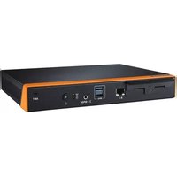
DS-780 - Digital media player Advantech - Free user manual and instructions
Find the device manual for free DS-780 Advantech in PDF.


| Product Type | Embedded Digital Signage Player |
| Dimensions (W x D x H) | 200 x 200 x 50 mm |
| Weight | 1.5 kg |
| Power Supply | 12V DC, 5A (60W max) |
| CPU | Intel Core i5-8250U (quad-core, 1.6 GHz up to 3.4 GHz) |
| RAM | 8 GB DDR4 (upgradable to 16 GB) |
| Storage | 128 GB M.2 SSD (expandable via SATA) |
| Operating System | Windows 10 IoT Enterprise LTSC |
| Graphics | Intel UHD Graphics 620 (supports 4K at 60 Hz) |
| Video Outputs | 1 x HDMI 2.0, 1 x DisplayPort 1.2 |
| USB Ports | 4 x USB 3.0, 2 x USB 2.0 |
| Ethernet | 1 x Gigabit LAN (Intel I210-IT) |
| Wireless Connectivity | 802.11ac Wi-Fi + Bluetooth 4.2 (optional module) |
| Audio | Line-out, microphone-in (3.5 mm jacks) |
| Operating Temperature | 0 °C to 50 °C |
| Cooling | Fanless design with aluminum heatsink |
| Mounting | VESA 75 x 75 mm, wall-mount bracket included |
| Included Accessories | Power adapter, Wi‑Fi antenna, mounting screws |
| Certifications | CE, FCC, RoHS |
Frequently Asked Questions - DS-780 Advantech
User questions about DS-780 Advantech
0 question about this device. Answer the ones you know or ask your own.
Ask a new question about this device
Download the instructions for your Digital media player in PDF format for free! Find your manual DS-780 - Advantech and take your electronic device back in hand. On this page are published all the documents necessary for the use of your device. DS-780 by Advantech.
USER MANUAL DS-780 Advantech
natural_image
Illustration of four electronic circuit boards with white outlines on a purple background (no text or symbols)DS-780
Multi-Display Digital Signage Player with Fanless Design
Copyright
The documentation and the software included with this product are copyrighted 2016 by Advantech Co., Ltd. All rights are reserved. Advantech Co., Ltd. reserves the right to make improvements in the products described in this manual at any time without notice. No part of this manual may be reproduced, copied, translated or transmitted in any form or by any means without the prior written permission of Advantech Co., Ltd. Information provided in this manual is intended to be accurate and reliable. However, Advantech Co., Ltd. assumes no responsibility for its use, nor for any infringements of the rights of third parties, which may result from its use.
Acknowledgements
VGA are trademarks of International Business Machines Corporation.
Intel® and Celeron® are trademarks of Intel Corporation.
Microsoft Windows® is a registered trademark of Microsoft Corp.
AMI is a registered trademark of American Megatrends Inc.
ESS is a trademark of ESS Technology, Inc.
All other product names or trademarks are properties of their respective owners.
For more information about this and other Advantech products, please visit our website at: http://www.advantech.com/
For technical support and service, please visit our support website at:
http://support.advantech.com.tw/support/
Part No. Edition 1
Printed in Taiwan October 2016
Product Warranty (2 years)
Advantech warrants to you, the original purchaser, that each of its products will be free from defects in materials and workmanship for two years from the date of purchase.
This warranty does not apply to any products which have been repaired or altered by persons other than repair personnel authorized by Advantech, or which have been subject to misuse, abuse, accident or improper installation. Advantech assumes no liability under the terms of this warranty as a consequence of such events.
Because of Advantech's high quality-control standards and rigorous testing, most of our customers never need to use our repair service. If an Advantech product is defective, it will be repaired or replaced at no charge during the warranty period. For out-of-warranty repairs, you will be billed according to the cost of replacement materials, service time and freight. Please consult your dealer for more details.
If you think you have a defective product, follow these steps:
- Collect all the information about the problem encountered. (For example, CPU speed, Advantech products used, other hardware and software used, etc.) Note anything abnormal and list any onscreen messages you get when the problem occurs.
- Call your dealer and describe the problem. Please have your manual, product, and any helpful information readily available.
- If your product is diagnosed as defective, obtain an RMA (return merchandise authorization) number from your dealer. This allows us to process your return more quickly.
- Carefully pack the defective product, a fully-completed Repair and Replacement Order Card and a photocopy proof of purchase date (such as your sales receipt) in a shippable container. A product returned without proof of the purchase date is not eligible for warranty service.
- Write the RMA number visibly on the outside of the package and ship it prepaid to your dealer.
Technical Support and Assistance
- Visit the Advantech website at http://support.advantech.com where you can find the latest information about the product.
- Contact your distributor, sales representative, or Advantech's customer service center for technical support if you need additional assistance. Please have the following information ready before you call:
– Product name and serial number
– Description of your peripheral attachments
– Description of your software (operating system, version, application software, etc.)
– A complete description of the problem
– The exact wording of any error messages
Warnings, Cautions and Notes
Warning! Warnings indicate conditions, which if not observed, can cause personal injury!

Caution! Cautions are included to help you avoid damaging hardware or losing data. e.g.

There is a danger of a new battery exploding if it is incorrectly installed. Do not attempt to recharge, force open, or heat the battery. Replace the battery only with the same or equivalent type recommended by the manufacturer. Discard used batteries according to the manufacturer's instructions.
Note! Notes provide optional additional information.

Declaration of Conformity
FCC Class B
Note: This equipment has been tested and found to comply with the limits of a Class B digital device, pursuant to part 15 of the FCC Regulations. These limits are designed to provide reasonable protection against harmful interference in a residential installation. This equipment generates, uses, and can radiate radio frequency energy and, if not installed and used in accordance with the instructions, may cause harmful interference to radio communications. However, there is no guarantee that interference will not occur in a particular installation. If the equipment does cause harmful interference to radio or television reception, as determined by turning the equipment off and on again, users are encouraged to try to correct the interference by performing one or more of the following actions:
■ Reorient or relocate the receiving antenna.
■ Increase the separation between the equipment and receiver.
■ Connect the equipment into an outlet on a circuit different from that to which the receiver is connected.
- Consult the dealer or an experienced radio/TV technician for assistance.
Packing List
Before installation, please ensure the following items have been shipped:
1 x DS-780 Unit
■ 1 x accessory box including:
- 1 x Power Adaptor
- 1 x Bracket set for fixing power adapter plug
- 2 x Mounting Brackets
- 1 x China RoHS
- 1 x User Manual
- 1 x Content Management Software
- 4 x Foot rubbers and screws
Optional Accessory
Part Number Description
1700001524 3-pin power cord (US)
170203183C 3-pin power cord (EU)
170203180A 3-pin power cord (UK)
1702031836 3-pin power cord (AU)
1700008921 3-pin power cord with PSE (Japan)
1700019146 3-pin power cord with CCC (China)
O
Safety Instructions
- Read these safety instructions carefully.
- Keep this User Manual for later reference.
- Disconnect this equipment from any AC outlet before cleaning. Use a damp cloth. Do not use liquid or spray detergents for cleaning.
- For plug-in equipment, the power outlet socket must be located near the equipment and must be easily accessible.
- Keep this equipment away from humidity.
- Put this equipment on a reliable surface during installation. Dropping it or letting it fall may cause damage.
- The openings on the enclosure are for air convection. Protect the equipment from overheating. DO NOT COVER THE OPENINGS.
- Make sure the voltage of the power source is correct before connecting the equipment to the power outlet.
- Position the power cord so that people cannot step on it. Do not place anything over the power cord.
- All cautions and warnings on the equipment should be noted.
- If the equipment is not used for a long time, disconnect it from the power source to avoid damage by transient overvoltage.
- Never pour any liquid into an opening. This may cause fire or electrical shock.
- Never open the equipment. For safety reasons, the equipment should be opened only by qualified service personnel.
- If one of the following situations arises, get the equipment checked by service personnel:
■ The power cord or plug is damaged.
- Liquid has penetrated into the equipment.
■ The equipment has been exposed to moisture.
The equipment does not work well, or you cannot get it to work according to the user's manual.
■ The equipment has been dropped and damaged.
■ The equipment has obvious signs of breakage.
-
DO NOT LEAVE THIS EQUIPMENT IN AN ENVIRONMENT WHERE THE STORAGE TEMPERATURE MAY GO BELOW -20°C (-4°F) OR ABOVE 60°C (140°F). THIS COULD DAMAGE THE EQUIPMENT. THE EQUIPMENT SHOULD BE IN A CONTROLLED ENVIRONMENT.
-
CAUTION: DANGER OF EXPLOSION IF BATTERY IS INCORRECTLY REPLACED. REPLACE ONLY WITH THE SAME OR EQUIVALENT TYPE RECOMMENDED BY THE MANUFACTURER, DISCARD USED BATTERIES ACCORDING TO THE MANUFACTURER'S INSTRUCTIONS.
DISCLAIMER: This set of instructions is given according to IEC 60950-1(ed.2). Advantech disclaims all responsibility for the accuracy of any statements contained herein.
Contents
Chapter 1 General Introduction ......1
1.1 Introduction 2
1.2 Product Features.... 2
1.2.1 General 2
1.2.2 Display 2
1.2.3 Power Consumption.... 2
1.3 Hardware Specifications 3
1.4 Mechanical Specifications.... 4
1.4.1 Dimensions 4
Figure 1.1 DS-780 mechanical dimensions.... 4
1.4.2 Weight.... 4
1.5 Power Requirements.... 4
1.5.1 System Power.... 4
1.5.2 RTC Battery 4
1.6 Environment Specification.... 5
1.6.1 Operating Temperature.... 5
1.6.2 Relative Humidity....5
1.6.3 Storage Temperature.... 5
1.6.4 Vibration Loading During Operation.... 5
1.6.5 Shock During Operation.... 5
1.6.6 Safety....5
1.6.7 EMC....5
Chapter 2 Hardware Installation ....7
2.1 DS-780 Front and Rear Views 8
Figure 2.1 Front view....8
Figure 2.2 Rear view....8
2.2 DS-780 Front External I/O Connectors 9
2.2.1 Power ON/OFF Button....9
Figure 2.3 Power button 9
2.2.2 S/PDIF / Line out / Mic-in Connector 9
Figure 2.4 S/PDIF / Line out / Mic-in connector....9
2.2.3 USB Connectors 9
Figure 2.5 USB connector 9
Table 2.1: USB 3.0 Connector Pin Assignments....9
2.2.4 Ethernet Connector (LAN) 10
Figure 2.6 LAN connector.... 10
Table 2.2: LAN Connector Pin Assignments 10
2.3 DS-780 Rear External I/O Connectors....10
2.3.1 Power Input Connector 10
Figure 2.7 DC input connector.... 10
2.3.2 HDMI Connector 11
Figure 2.8 HDMI connector.... 11
Table 2.3: HDMI Connector Pin Assignments.... 11
2.3.3 USB Connectors 11
Figure 2.9 USB 3.0 connector 11
2.3.4 COM Connector.... 12
Figure 2.10COM connector 12
Table 2.4: COM Port Pin Assignments.... 12
2.4 Hardware Installation 13
2.4.1 Memory Installation.... 13
Figure 2.11Memory module installation-Top side.... 13
Figure 2.12Memory module installation-bottom side.... 14
2.4.2 HDD/SSD Installation .... 15 Figure 2.13HDD/SSD installation .... 15
2.4.3 Mini PCIe card / M.2 / SIM Card and Antenna Installation .... 16 Figure 2.14Mini PCIe / M.2 / SIM card installation .... 16 Figure 2.15Antenna module installation .... 17
2.4.4 Mount Brackets Installation.... 18 Figure 2.16Mount brackets installation.... 18
2.4.5 Rubber Feet Installation.... 19 Figure 2.17Rubber feet Installation .... 19
Chapter 3 BIOS Settings....21
3.1 BIOS Introduction.... 22
3.2 Entering Setup 22
3.2.1 Main Setup.... 22 Figure 3.1 Main setup screen.... 22
3.2.2 Advanced BIOS Setup.... 23 Figure 3.2 Advanced BIOS setup screen.... 23 Figure 3.3 ACPI setup screen.... 24
3.2.3 BIOS Chipset setup .... 31 Figure 3.4 BIOS Chipset setup.... 31
3.2.4 BIOS Security setup .... 33 Figure 3.5 BIOS Security setup.... 33
3.2.5 BIOS Boot setup.... 34 Figure 3.6 BIOS Boot setup.... 34
3.2.6 BIOS Save& Exit setup.... 35 Figure 3.7 BIOS Save& Exit setup .... 35
Chapter 1
General Introduction
This chapter gives background information of DS-780 series.
1.1 Introduction
Digital signage is one of the most effective and eye-catching communications mediums on the market. Advantech DS-780 is an ideal digital signage player. It's not only a high graphic performance computer but also a low power for advanced Digital Signage Player. It powered by 6th generation Intel® Core™ U series processor and designed with fanless solution. DS-780 supports 4K resolution by HDMI outputs and has slide-in chassis design for maintaining the storage device easily.
The 6th generation Intel® Core™ U series support of HEVC / H.265 video decoding. The HEVC / H.265 video compression technology can reduce video file size, reducing the occupied storage space, but also to reduce the network transmission network bandwidth consumed, it is suitable for playing high-resolution video request.
DS-780 has 3 x HDMI ports to support triple display output simultaneously. And has 2 x GbE ports, 4 USB 3.0 ports, 1 x COM (RS-232) and 1 x combo Audio port (SPDIF / Line-out / Mic-in) for system integration and application. For better connectivity, it supports 1 x mini PCIe interface for add-on functions such as wireless modules, 3G modules. DS-780 also supports 1 x M.2 (2230/1630 E Key) interface for WIFI modules.
As a high performance and low power design with fanless solution, DS-780 is ideal for single to triple display applications in stores, lobbies, restaurants, FIDS and other display public spaces.
1.2 Product Features
1.2.1 General
6th Gen. Intel® Core™ U series i7-6650U /i7-6600U/ i5-6360U /i5-6300U/i3-6100U/Celeron-3955U processors (CPU TDP up to 15W)
■ Supports 3 x HDMI ports (1 x HDMI 2.0, 2 x HDMI 1.4*)
■ Supports 2 x GbE, 4 x USB 3.0 and 1 x COM(RS-232)
■ Supports 2.5-inch SATA HDD/SSD drive bay for storage devices
Built-in 1 x Mini PCIe slot for easy expansion e.g. WiFi, 3G etc
Built-in 1 x M.2 slot (2230/1630 E Key) for easy expansion with WIFI modules * One of the HDMI 1.4 (HDMI3) no support Audio, HDCP and Hot plug and no display in BIOS and DOS.
1.2.2 Display
Resolution:
– HDMI 2.0: 3840 x 2160 @60Hz
– HDMI 1.4: 3840 x 2160 @24Hz
1.2.3 Power Consumption
■ Idle: 8.35 W (w/o expansion)
■ Max.: 23.3 W (w/o expansion)
1.3 Hardware Specifications
CPU: Intel® Core™ Skylake-U series i7-6650U /i7-6600U/ i5-6360U /i5-6300U/ i3-6100U/Celeron-3955U
System Chipset: SoC solution, built-in Intel® Core™ Skylake-U processor
BIOS: AMI uEFI 64 Mbit Flash BIOS
System Memory: 2 x DDR4 SO-DIMM sockets, support DDR4 2133 MHz up to 32 GB (Max. 16GB per each SO-DIMM socket)
- Processor Graphics: Intel® IRIS Graphics 540 (i7-6650U / i5-6360U), Intel® HD Graphics 520 (i7-6600U/i5-6300U/i3-6100U), Intel® HD Graphics 510 (Celeron-3955U)
■ Storage: Supports 1 x 2.5" SATA HDD/SSD
■ Watchdog Timer: Supported by Advantech SUSIAccess API
I/O Interface:
- COM: 1 x RS-232
- USB: 4 x USB 3.0
- Audio: 1 x SPDIF / Line-Out / Mic-in
Ethernet Chipset: 1 x Intel i219, 1 x Realtek 8111G
■ Speed: 10/100/1000 Mbps
■ Interface: 2 x RJ-45 jacks with LED
Standard: IEEE 802.3 (10 / 1000 Base-T, 100 Base-TX) or IEEE 802.3u (Auto-Negotiation)
■ Expansion
- Mini PCIe: 1 socket internal (Full size), support mSATA interface
- M.2(2230/1630 E Key).
1.4 Mechanical Specifications
1.4.1 Dimensions
235 x 175 x 35 mm (9.25" x 6.89" x 1.38") (W x D x H)
![235.9 [0.5] 12.50 [41] 37.25 147 d 10.5 [39] d 4 (0.18) d 3.55 [14] 3 [0.118] 1.26 [0.047] 279 [8.627] 2.61 [4.0] 11.25 [44] 52.2 [0.5] 74.50 2 [0.3] 7.25 [29] 22.50 [63] 35 [1.376] 7 [0.276] 208 [9.110] 47.50 [60.67] 131.50 [51.77/21 40 [0.363] 14.50 [0.571]](/content/2026/05/1002132/images/bd9329e8bdc60a310ae3f4c6c7c9f45401a217024ff1eab4ac30c41f16f59175.jpg)
Figure 1.1 DS-780 mechanical dimensions
1.4.2 Weight
1.5 kg (3.3 lb)
1.5 Power Requirements
1.5.1 System Power
Minimum power input: DC 19V, 3.42A
1.5.2 RTC Battery
3V/220 mAh CR2032
1.6 Environment Specification
1.6.1 Operating Temperature
0^ C - 40^ C (32 104 ^ F) with 0.7m/s air flow
1.6.2 Relative Humidity
95% @ 40°C (non-condensing)
1.6.3 Storage Temperature
-20^ C 60^ C (-4 \~ 140° F)
1.6.4 Vibration Loading During Operation
■ 1.0 Grms, IEC 60068-2-64, random, 5 \~ 500 Hz, 3 axes, 1 hr/axis.
1.6.5 Shock During Operation
■ 10 G, IEC 60068-2-27, half sine, 11 ms duration
1.6.6 Safety
UL,CB,BSMI,CCC
1.6.7 EMC
CE/FCC Class B, BSMI, CCC
Chapter 2
Hardware Installation
This chapter describes DS-780 external I/O and explains the hardware installation processes.
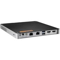
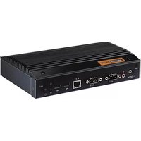
2.1 DS-780 Front and Rear Views

Figure 2.1 Front view
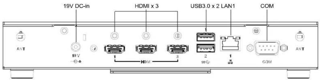
Figure 2.2 Rear view
2.2 DS-780 Front External I/O Connectors
2.2.1 Power ON/OFF Button
DS-780 has a power ON/OFF button on front side. Push this button to turn the system ON and OFF. It can also support 4 second delay soft power off.

Figure 2.3 Power button
2.2.2 S/PDIF / Line out / Mic-in Connector
The connector port is a combo connector. It not only allows you to transfer digital sound to an amplifier or television but also can be the Line out and Microphone (Input) functions. It supports Jacks sensing and configuration can be conducted via the driver UI.

Figure 2.4 S/PDIF / Line out / Mic-in connector
2.2.3 USB Connectors
DS-780 front side provides 2 x USB3.0 interface connectors, which give complete Plug & Play and hot swapping capability for up to 127 external devices. The two USB 3.0 interface are compliant with USB UHCI, Rev. 3.0. (Refer to Table 2.1 for pin definitions)

Figure 2.5 USB connector
Table 2.1: USB 3.0 Connector Pin Assignments
| Pin Signal Name | |
| 1 VBUS | |
| 2 USB Data- | |
| 3 USB Data+ | |
| 4 | GND |
| 5 StdA_SSRX- | |
| 6 StdA_SSRX+ | |
| 7 GND_DRAIN | |
| 8 StdA_SSTX- | |
| 9 StdA_SSTX+ | |
2.2.4 Ethernet Connector (LAN)
DS-780 provides two RJ45 LAN interface connectors (1 x LAN in front-side; 1 x LAN in rear-side), they are fully compliant with IEEE 802.3u 10/100/1000 Base-T standards. The Ethernet port provides a standard RJ-45 jack connector with LED indicators on the front side to show its Active/Link status and speed status.
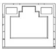
Figure 2.6 LAN connector
Table 2.2: LAN Connector Pin Assignments
| Pin Signal Name | |||
| 1 | M | D | I |
| 2 | M | D | I |
| 3 | M | D | I |
| 4 | M | D | I |
| 5 | GND | ||
| 6 | GND | ||
| 7 | M | D | I |
| 8 | M | D | I |
| 9 | MDI3+ | ||
| 10 | MDI3- | ||
| 11 | VCC | ||
| 12 | ACT | ||
| 13 | Link100# | ||
| 14 | Link1000# | ||
2.3 DS-780 Rear External I/O Connectors
2.3.1 Power Input Connector
DS-780 comes with a DC-Jack header that takes 19 VDC external power input.

Figure 2.7 DC input connector
2.3.2 HDMI Connector
DS-780 HDMI (High-Definition Multimedia Interface) connectors provide all-digital audio/video interface to transmit the uncompressed audio/video signals and are HDCP compliant. Connect the HDMI audio/video device to this port. HDMI technology can support a maximum resolution of 3840 x 2160p (Ultra HD 4K) but the actual resolutions supported depend on the monitor being used.
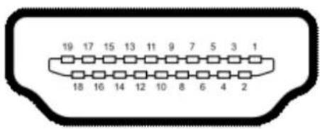
Figure 2.8 HDMI connector
Table 2.3: HDMI Connector Pin Assignments
| Pin Signal Name | |||
| 1 | T | M | D |
| 2 | GND | ||
| 3 | T | M | D |
| 4 | T | M | D |
| 5 | GND | ||
| 6 | T | M | D |
| 7 | T | M | D |
| 8 | GND | ||
| 9 | T | M | D |
| 10 TMDS Clock+ | |||
| 11 GND | |||
| 12 TMDS Clock- | |||
| 13 NC | |||
| 14 NC | |||
| 15 SCL | |||
| 16 SDA | |||
| 17 GND | |||
| 18 +5 V Power | |||
| 19 Detect | |||
2.3.3 USB Connectors
DS-780 rear side provides 2 x USB3.0 interface connectors, which give complete Plug & Play and hot swapping capability for up to 127 external devices.
The USB 3.0 is compliant with USB UHCI, Rev. 3.0. (Pin definition refer Table 2.1)

Figure 2.9 USB 3.0 connector
2.3.4 COM Connector
DS-780 provides 1 x D-sub 9-pin connectors serial communication interface port. The port can support RS-232 mode communication.
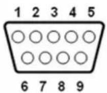
Figure 2.10 COM connector
Table 2.4: COM Port Pin Assignments
| Pin Signal Name | |
| 1 | DCD |
| 2 | RxD |
| 3 | TxD |
| 4 | DTR |
| 5 | GND |
| 6 | DSR |
| 7 | RTS |
| 8 | CTS |
| 9 | RI |
2.4 Hardware Installation
2.4.1 Memory Installation
[Top side]
- Loosening the 4 fixing screws on the side of top cover.
- Remove the top cover.
- Insert the memory module into memory socket
- Assemble back the heatsink cover with the 4 screws

Figure 2.11 Memory module installation-Top side
[Bottom side]
- Loosening the 1 fixing screw on the memory cover in bottom side.
- Remove the memory cover.
- Insert the memory module into memory socket
- Assemble back the memory cover with the 1 screw.

Figure 2.12 Memory module installation-bottom side
2.4.2 HDD/SSD Installation
- Loosening the screw on the front view and move out the drive bay.
- Fixing the 4 screws with HDD/SSD and storage bracket.
- Insert the storage bracket into chassis
- Fixing the screw back.

Figure 2.13 HDD/SSD installation
2.4.3 Mini PCIe card / M.2 / SIM Card and Antenna Installation
- Loosening the fixing screw on the mini PCIe cover and remove the cover..
- Insert the mini PCIe module / M.2 / SIM card into the sockets and fix it with screws
- Loosening the 4 fixing screws on the side of top cover
- Attach the antenna module to the ant holes of chassis
- Assemble the antenna cable to mini PCIe/ M.2 module on the bottom side.
- Assemble back the mini PCIe cover with the screw.
- Assemble back the top cover with the screws
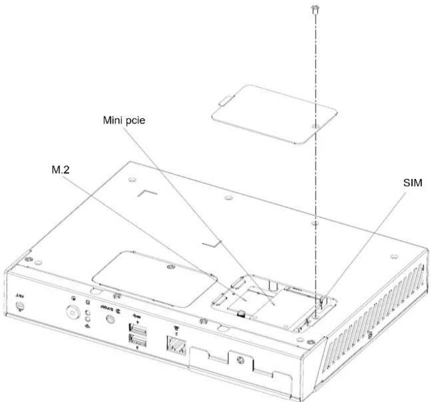
Figure 2.14 Mini PCIe / M.2 / SIM card installation

Figure 2.15 Antenna module installation
2.4.4 Mount Brackets Installation
- Loosening the fixing screws on the bottom side.
- Fixing the two mount brackets with 4 screws directly.

Figure 2.16 Mount brackets installation
2.4.5 Rubber Feet Installation
- Retrieve the four rubber feet from the accessory box.
- Attach the rubber feet to the four corners and fixing them by four screws directly.

natural_image
Line drawing of a computer tower with multiple vertical connectors and ventilation slots (no text or symbols)Figure 2.17 Rubber feet Installation
Chapter 3
BIOS Settings
This chapter introduces how to set BIOS configuration data.
3.1 BIOS Introduction
Using the AMI BIOS Setup program, users can modify the BIOS settings and control various system features. This chapter describes the basic navigation of the BIOS setup screens for the DS-780 series.
The AMI BIOS's ROM features a built-in setup program that allows users to modify the basic system configuration. This information is stored in the flash portion of the CMOS to ensure the setup information is retained even when the system is powered off.
3.2 Entering Setup
3.2.1 Main Setup
When first entering the BIOS Setup Utility, users will land on the Main setup screen. Users can always return to the Main setup screen by selecting the Main tab.
The Main BIOS setup screen features two main frames. The left frame displays all configurable options. The blue options can be configured, whereas the gray options cannot. The right frame displays the key legend, above which is an area reserved for text messages. When an option is selected in the left frame, the text becomes white and is often accompanied by a text message.
![Aptio Setup Utility - Copyright (C) 2016 American Megatrends, Inc. Main Advanced Chipset Security Boot Save & Exit BIOS Information BIOS Vendor American Megatrends Core Version 5.0.1.1 0.31 x64 Compliancy UEFI 2.4; PI 1.3 Project Version DS D780000U060X014 Build Date and Time 05/10/2016 14:11:29 Access Level Administrator Power Type ATX Total Memory 8192 MB Memory Frequency 2133 MHz ME FW Version 11.0.0.1205 ME Firmware SKU Corporate SKU System Language [English] System Date [Sun 01/07/2046] System Time [11:18:11] Choose the system default language +: Select Screen ↑↓: Select Item Enter: Select +/-: Change Opt. F1: General Help F2: Previous Values F3: Optimized Defaults F4: Save & Exit ESC: Exit Version 2.17.1255. Copyright (C) 2016 American Megatrends, Inc.](/content/2026/05/1002132/images/100d68038132ca193d53b705d33a122bcdee3f2095c63d519baa3ac669d54ac7.jpg)
Figure 3.1 Main setup screen
■ System Time/System Date
Use this option to change the system time and date. Highlight System Time or System Date using the
3.2.2 Advanced BIOS Setup
Select the Advanced tab from the DS-780 setup screen to enter the Advanced BIOS setup screen. You can select any of the items in the left frame of the screen, such as CPU configuration, to go to the sub menu for that item. You can display an Advanced BIOS Setup option by highlighting it using the

Figure 3.2 Advanced BIOS setup screen
ACPI Settings
This item allows users to control hardware monitoring and power management.
![Aptio Setup Utility - Copyright (C) 2016 American Megatrends, Inc. Advanced ACPI Settings Enable ACPI Auto Configuration [Disabled] Enable Hibernation [Enabled] ACPI Sleep State [S3 (Suspend to RAM)] Lock Legacy Resources [Disabled] Enables or Disables BIOS ACPI Auto Configuration. ++: Select Screen ↑↓: Select Item Enter: Select +/-: Change Opt. F1: General Help F2: Previous Values F3: Optimized Defaults F4: Save & Exit ESC: Exit Version 2.17.1255. Copyright (C) 2016 American Megatrends, Inc.](/content/2026/05/1002132/images/07d97e966863753a7ad881a944cb379020c8e6860a338ce3a26ee4f46b386496.jpg)
Figure 3.3 ACPI setup screen
■ AMT Configuration
This section is used to configure Active Management Technology (AMT) options. Intel® AMT Enables or disables Active Management Technology
![Aptio Setup Utility - Copyright (C) 2016 American Megatrends, Inc. Advanced Intel AMT [Enabled] BIOS Hotkey Pressed [Disabled] MEBx Selection Screen [Disabled] Hide Un-Configure ME Confirmation [Disabled] Prompt MEBx Debug Message Output [Disabled] Un-Configure ME [Disabled] Amt Wait Timer 0 ASF [Enabled] Activate Remote Assistance Process [Disabled] USB Provisioning of AMT [Enabled] PET Progress [Enabled] AMT CIRA Timeout 0 WatchDog [Disabled] OS Timer 0 BIOS Timer 0 Enable/Disable Intel (R) Active Management Technology BIOS Extension. Note : iAMT H/H is always enabled. This option just controls the BIOS extension execution. If enabled, this requires additional firmware in the SPI device +: Select Screen 1↓: Select Item Enter: Select +/-: Change Opt. F1: General Help F2: Previous Values F3: Optimized Defaults F4: Save & Exit ESC: Exit Version 2.17.1255. Copyright (C) 2016 American Megatrends, Inc.](/content/2026/05/1002132/images/c2ab5f7d71772bc24c29473bff56aa309208ebb3ccb609dacdabf8b1f3fbec3c.jpg)
■ PCH-FW Configuration
Configure Management Engine Technology Parameters
![Aptio Setup Utility - Copyright (C) 2016 American Megatrends, Inc. Advanced ME FW Version 11.0.0.1205 ME Firmware Mode Normal Mode ME Firmware Type Full Sku Firmware ME Firmware SKU Corporate SKU ME State [Enabled] ▶ Firmware Update Configuration Configure Management Engine Technology Parameters +: Select Screen ↓: Select Item Enter: Select +/-: Change Opt. F1: General Help F2: Previous Values F3: Optimized Defaults F4: Save & Exit ESC: Exit Version 2.17.1255. Copyright (C) 2016 American Megatrends, Inc.](/content/2026/05/1002132/images/059d46ff1979d13ce0ead2884e56e32fca1d3485eb190354125764af6ed8d397.jpg)
■ ITE8528E Super I/O Configuration
System super I/O chip parameters

■ ITE8528E HW Monitor
Enabled or disabled watch dog timer function (Start before boot to OS and must by self)
![Aptio Setup Utility - Copyright (C) 2016 American Megatrends, Inc. Advanced PC Health Status EC Firmware Version I286EX0006 CPU temperature : +68°C System temperature : +27°C VBAT : +3.014 V 5VSB : +5.014 V +5V : +5.026 V +3.3V : +3.306 V Watch Dog Timer [Disabled] Enabled or Disabled Watch Dog Timer function (Start before boot to OS and must stop by self) +: Select Screen ↑↓: Select Item Enter: Select +/-: Change Opt. F1: General Help F2: Previous Values F3: Optimized Defaults F4: Save & Exit ESC: Exit Version 2.17.1255. Copyright (C) 2016 American Megatrends, Inc.](/content/2026/05/1002132/images/15225db594158f9b15fc753555523b24e5eec8ff704ddc0b45eb8a4cf71fea31.jpg)
S5 RTC Wake Settings
Enable or disable system wake on alarm event.
![Aptio Setup Utility - Copyright (C) 2016 American Megatrends, Inc. Advanced Wake system from S5 [Disabled] Enable or disable System wake on alarm event. Select FixedTime, system will wake on the hr::min::sec specified. Select DynamicTime , System will wake on the current time + Increase minute(s) +: Select Screen ↑↓: Select Item Enter: Select +/-: Change Opt. F1: General Help F2: Previous Values F3: Optimized Defaults F4: Save & Exit ESC: Exit Version 2.17.1255. Copyright (C) 2016 American Megatrends, Inc.](/content/2026/05/1002132/images/6c0dfc562a6cb60cdbf7519b3f7a29aaa075c9835afe2821c57971b08a64cf37.jpg)
Serial Port Console Redirection
Console redirection enable or disable
![Aptio Setup Utility - Copyright (C) 2016 American Megatrends, Inc. Advanced COM1 Console Redirection [Disabled] ► Console Redirection Settings Legacy Console Redirection ► Legacy Console Redirection Settings Serial Port for Out-of-Band Management/ Windows Emergency Management Services (EMS) Console Redirection [Disabled] ► Console Redirection Settings Console Redirection Enable or Disable. +: Select Screen +: Select Item Enter: Select +/-: Change Opt. F1: General Help F2: Previous Values F3: Optimized Defaults F4: Save & Exit ESC: Exit Version 2.17.1255. Copyright (C) 2016 American Megatrends, Inc.](/content/2026/05/1002132/images/d3625172539e5c2cd36e4a960c9b48a99da43860c0b6d12c86a3787f5ad2bfc0.jpg)
CPU Configuration
CPU configuration parameters
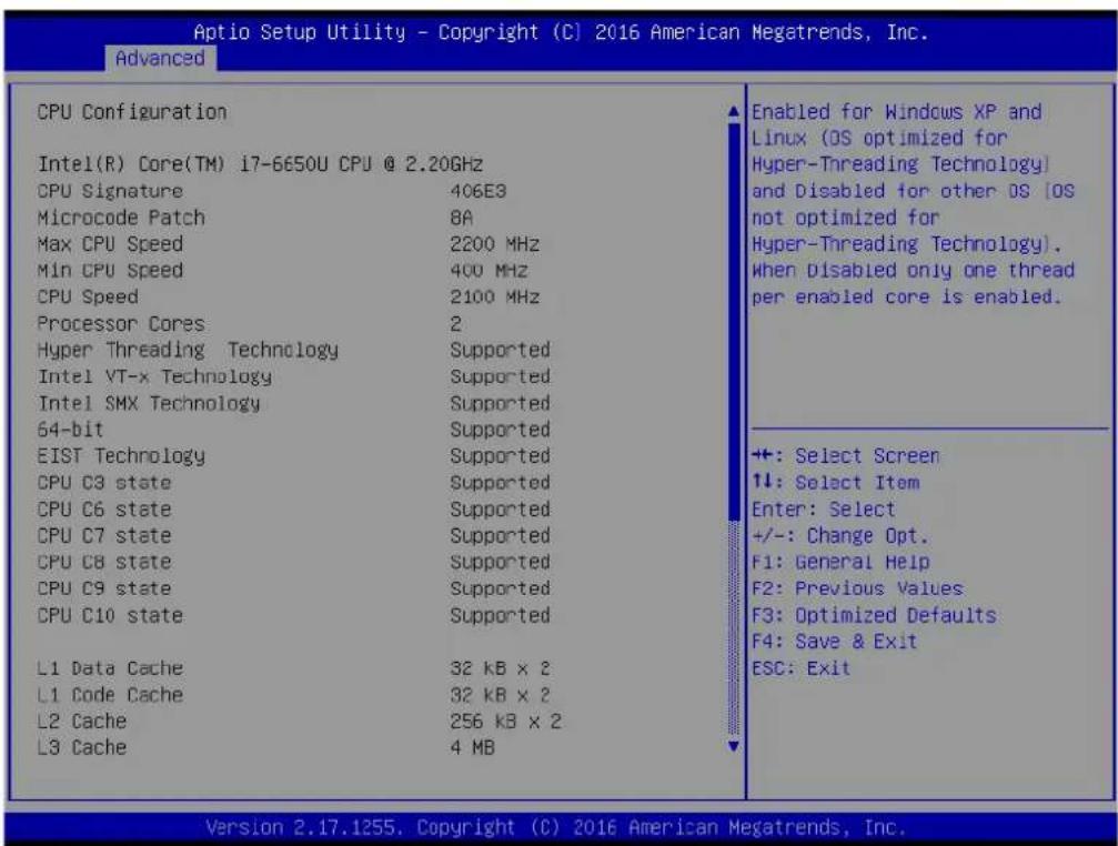
Intel TXT Information

■ SATA Configuration
Enable or disable SATA Device
![Aptio Setup Utility - Copyright (C) 2016 American Megatrends, Inc. Advanced SATA Controller(s) SATA Mode Selection Serial ATA Port 1 Software Preserve Port 1 SATA Device Type mSATA Software Preserve mSATA SATA Device Type [Enabled] [AHCI] Empty Unknown [Enabled] [Hard Disk Drive] Empty Unknown [Enabled] [Hard Disk Drive] Enable or disable SATA Device. +: Select Screen ↑↓: Select Item Enter: Select +/-: Change Opt. F1: General Help F2: Previous Values F3: Optimized Defaults F4: Save & Exit ESC: Exit Version 2.17.1255. Copyright (C) 2016 American Megatrends, Inc.](/content/2026/05/1002132/images/141f161095852f36aa858d4be6318b4775351a29112e3f4f9c1c22133510a9c6.jpg)
■ Network Stack configuration
Enable/Disable UEFI network stack.
![Aptio Setup Utility - Copyright (C) 2016 American Megatrends, Inc. Advanced Network Stack [Disabled] Enable/Disable UEFI Network Stack +: Select Screen ↑↓: Select Item Enter: Select +/-: Change Opt. F1: General Help F2: Previous Values F3: Optimized Defaults F4: Save & Exit ESC: Exit Version 2.17.1255. Copyright (C) 2016 American Megatrends, Inc.](/content/2026/05/1002132/images/392b6119e90c7ee731e26046cf720c64cf96a72ec5c31bdf90360823d4eebca7.jpg)
CSM Configuration
Enable/disable option ROM execution
![Aptio Setup Utility - Copyright (C) 2016 American Megatrends, Inc. Advanced Compatibility Support Module Configuration CSM Support [Enabled] CSM16 Module Version 07.79 GateA20 Active [Upon Request] INT19 Trap Response [Immediate] Boot option filter [UEFI only] Option ROM execution Network [UEFI] Storage [UEFI] Video [UEFI] Other PCI devices [UEFI] Enable/Disable CSM Support. ++: Select Screen 1↓: Select Item Enter: Select +/-: Change Opt. F1: General Help F2: Previous Values F3: Optimized Defaults F4: Save & Exit ESC: Exit Version 2.17.1255, Copyright (C) 2016 American Megatrends, Inc.](/content/2026/05/1002132/images/ac76c1c81a7047ad860d899f9b028d7083b60d7df3385098cee79fa9ae807a4f.jpg)
USB Configuration
USB configuration parameters
– Legacy USB Support
Enable/disable legacy USB support. The Auto option disables legacy support if no USB devices are connected. The Disable option renders USB devices available for EFI applications only.
-XHCI Hand-Off
This provides a workaround for OS without XHCI hand-off support. The XHCI ownership change should be claimed by the XHCI driver.
- USB Mass Storage Driver Support
Enable/disable USB mass storage driver support
- Port 60/64 Emulation
Enables I/O port 60h/64h emulation support. This should be enabled for the complete USB keyboard legacy support for non-usb aware OSes.
- USB Transfer Timeout
Allows users to set the timeout value for control, bulk, and interrupt transfers; options include 1, 5, 10, and 20 seconds.
- Device Reset Timeout
Allows users to set the USB mass storage device start unit command timeout time; options include 10, 20, 30, and 40 seconds.
- Device Power-Up Delay
Enable/disable
![Aptio Setup Utility - Copyright (C) 2016 American Megatrends, Inc. Advanced USB Configuration USB Module Version 14 USB Controllers: 1 XHCI USB Devices: 1 Drive, 1 Keyboard, 1 Mouse, 1 Hub Legacy USE Support [Enabled] XHCI Hand-off [Enabled] USB Mass Storage Driver Support [Enabled] Port 60/64 Emulation [Disabled] USB hardware delays and time-outs: USB transfer time-out [20 sec] Device reset time-out [20 sec] Device power-up delay [Auto] Mass Storage Devices: KingstonDataTraveler 3.0PMAP [Auto] Enables Legacy USB support. AUTO option disables legacy support if no USB devices are connected. DISABLE option will keep USB devices available only for EFI applications. +: Select Screen ↑↓: Select Item Enter: Select +/-: Change Opt. F1: General Help F2: Previous Values F3: Optimized Defaults F4: Save & Exit ESC: Exit Version 2.17.1255. Copyright (C) 2016 American Megatrends, Inc.](/content/2026/05/1002132/images/166038f9af0e1563931b82969f3140099b90337fb62ca652fb0dc332f5aaf53e.jpg)
3.2.3 BIOS Chipset setup
Select the Chipset tab in the DS-780 BIOS Setup Utility to enter the BIOS Chipset setup screen. Users can select any item displayed in the left frame of the screen.
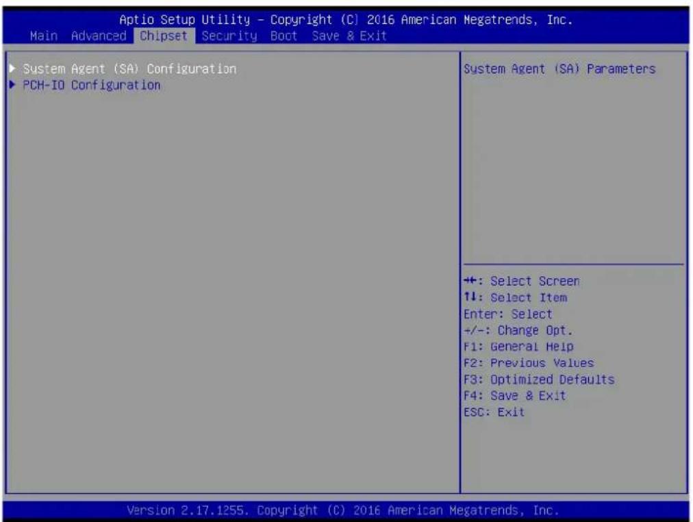
Figure 3.4 BIOS Chipset setup
■ System Agent (SA) Configuration
- Vt-d capability
- Graphics configuration
- GT - Power management control
- Max TOLUD
![Aptio Setup Utility - Copyright (C) 2016 American Megatrends, Inc. Chipset VT-d [Enabled]VT-d capability ► Graphics Configuration ► GT - Power Management Control Memory Configuration Total Memory 8192 MB DIMM A1 8192 MB DIMM B1 Not Present Max TOLUD [Dynamic] ++: Select Screen ↑↓: Select Item Enter: Select +/-: Change Opt. F1: General Help F2: Previous Values F3: Optimized Defaults F4: Save & Exit ESC: Exit Version 2.17.1255. Copyright (C) 2016 American Megatrends, Inc.](/content/2026/05/1002132/images/a9ee1791c493493f8dc1bc5cff94f00c00a401d5e5d24ad1ef24589d82490918.jpg)
■ PCH-IO Configuration
PCH-IO Parameters
- PCI Express Configuration
PCI Express Configuration settings
- USB Configuration
USB configuration settings
a.USB Precondition
b.XHCI Disable Compliance Mode
c. USB port Disable override
- HD Audio
Control detection of the HD-Audio device.
Disable=HDA will be unconditionally disabled
Enable=HDA will be unconditionally enabled
Auto= HDA will be enabled if present, disable otherwise.
- LAN1 Control
Enable or disable onboard NIC
- LAN2 Control
Enable or disable onboard NIC
- PCIe Wake
Enable/disable PCIE to wake the system from S5.
- Wake on WLAN Enable from DeepSx
Enable/Disable PCI Express wireless LAN to wake the system from DeepSx.
- State after G3
Specify what state to go to when power is re-applied after a power failure (S3 state)
3.2.4 BIOS Security setup
Select the Security tab from the setup screen to enter the BIOS Security setup screen.
Set Administrator Password and User password.

Figure 3.5 BIOS Security setup
3.2.5 BIOS Boot setup
Select the Boot tab from the DS-780 setup screen to enter the BIOS Boot setup screen. Users can select any item in the left frame of the screen.
![Aptio Setup Utility - Copyright (C) 2016 American Megatrends, Inc. Main Advanced Chipset Security Boot Save & Exit Boot Configuration Setup Prompt Timeout Bootup NumLock State Quiet Boot Boot Option Priorities Boot Option #1 Fast Boot New Boot Option Policy 1 [On] [Disabled] [LEFI: KingstonDataTraveler 3.0PMAP, Partition 1] [Disabled] [Default] Number of seconds to wait for setup activation key. 65535(0xFFFF) means indefinite waiting. +: Select Screen ↑↓: Select Item Enter: Select +/-: Change Opt. F1: General Help F2: Previous Values F3: Optimized Defaults F4: Save & Exit ESC: Exit Version 2.17.1255. Copyright (C) 2016 American Megatrends, Inc.](/content/2026/05/1002132/images/0b67a1d6ee2ceeb3e0c4a3eeb98bcb77a3762f4bba8477d114e638916d9db24c.jpg)
Figure 3.6 BIOS Boot setup
Setup Prompt Timeout
Allows users to set the number of seconds to wait for a setup activation key. A value of 65535 (0xFFFF) means wait indefinitely.
■ Bootup NumLock State
Allows users to select the keyboard NumLock state
Quiet Boot
Enable/disable quiet booting
■ Boot Option #1
Set the system boot order
Fast Boot
Enable/disable rapid booting by initializing the minimum number of devices necessary for launching the active boot option.
■ New boot option policy
Controls the placement of newly detected UEFI boot options.
3.2.6 BIOS Save& Exit setup
Select the Save & Exit tab from the setup screen to enter the BIOS Save & Exit setup screen.

Figure 3.7 BIOS Save& Exit setup
■ Save Changes and Exit
Exit system setup after saving changes
■ Discard Changes and Exit
Exit system setup without saving changes
■ Save Changes and Reset
Reset the system after saving changes
■ Discard Changes and Reset
Reset the system without saving changes
Save Changes
Save changes to all setup options
■ Discard Changes
Discard changes to all setup options
Restore Defaults
Restore/load the default values for all setup options
■ Save as User Defaults
Save changes as User Defaults
Restore User Defaults
Restore the User Defaults to all setup options
Boot Override
- Launch EFI Shell From File System Device
Allows users to launch the EFI Shell application (Shell.efi) from an available file system device
ADVANTECH
Enabling an Intelligent Planet
www.advantech.com
Please verify specifications before quoting. This guide is intended for reference purposes only.
All product specifications are subject to change without notice.
No part of this publication may be reproduced in any form or by any means, electronic, photocopying, recording or otherwise, without prior written permission of the publisher.
All brand and product names are trademarks or registered trademarks of their respective companies.
© Advantech Co., Ltd. 2016


- DS-780
- Multi-Display Digital Signage Player with Fanless Design
- Copyright
- Acknowledgements
- Product Warranty (2 years)
- Technical Support and Assistance
- Warnings, Cautions and Notes
- Declaration of Conformity
- FCC Class B
- Packing List
- Optional Accessory
- Safety Instructions
- Contents
- Chapter 1 General Introduction ......1
- Chapter 2 Hardware Installation ....7
- Chapter 3 BIOS Settings....21
- Chapter 1
- General Introduction
- Introduction
- Product Features
- General
- Display
- Power Consumption
- Hardware Specifications
- Mechanical Specifications
- Dimensions
- Weight
- Power Requirements
- System Power
- RTC Battery
- Environment Specification
- Operating Temperature
- Relative Humidity
- Storage Temperature
- Vibration Loading During Operation
- Shock During Operation
- Safety
- EMC
- Chapter 2
- DS-780 Front and Rear Views
- DS-780 Front External I/O Connectors
- Power ON/OFF Button
- S/PDIF / Line out / Mic-in Connector
- USB Connectors
- Ethernet Connector (LAN)
- DS-780 Rear External I/O Connectors
- Power Input Connector
- HDMI Connector
- USB Connectors
- COM Connector
- Hardware Installation
- Memory Installation
- [Top side]
- [Bottom side]
- HDD/SSD Installation
- Mini PCIe card / M.2 / SIM Card and Antenna Installation
- Mount Brackets Installation
- Rubber Feet Installation
- Chapter 3
- BIOS Settings
- BIOS Introduction
- Entering Setup
- Main Setup
- ■ System Time/System Date
- Advanced BIOS Setup
- ACPI Settings
- ■ AMT Configuration
- ■ PCH-FW Configuration
- ■ ITE8528E Super I/O Configuration
- ■ ITE8528E HW Monitor
- S5 RTC Wake Settings
- Serial Port Console Redirection
- CPU Configuration
- Intel TXT Information
- ■ SATA Configuration
- ■ Network Stack configuration
- CSM Configuration
- USB Configuration
- BIOS Chipset setup
- ■ System Agent (SA) Configuration
- ■ PCH-IO Configuration
- BIOS Security setup
- BIOS Boot setup
- Setup Prompt Timeout
- ■ Bootup NumLock State
- Quiet Boot
- ■ Boot Option #1
- Fast Boot
- ■ New boot option policy
- BIOS Save& Exit setup
- ADVANTECH
- www.advantech.com
Brand : Advantech
Model : DS-780
Category : Digital media player