
Surveillix EAV16 - Surveillance Camera TOSHIBA - Free user manual and instructions
Find the device manual for free Surveillix EAV16 TOSHIBA in PDF.


| Product Type | Digital Video Recorder (DVR) |
| Brand | Toshiba |
| Model | Surveillix EAV16 |
| Video Input Channels | 16 BNC |
| Compression Format | H.264 |
| Recording Resolution | Up to D1 (720x480) |
| Hard Drive Capacity | Up to 2 TB (SATA) |
| Network Interface | 10/100 Ethernet RJ-45 |
| Dimensions (W x H x D) | 430 x 44 x 340 mm |
| Weight | Approx. 4 kg (without HDD) |
| Power Supply | 100-240V AC, 50/60Hz |
| Power Consumption | 30W (typical) |
| Operating Temperature | 0°C to 40°C |
| Storage Temperature | -10°C to 60°C |
| Video Output | BNC, VGA |
| Audio Input/Output | 1 channel RCA |
| Alarm Input/Output | 16 inputs, 4 outputs |
| Remote Viewing | Via web browser or client software |
| Motion Detection | Yes, per channel |
| Backup | USB flash drive, network |
| Warranty | 1 year (depending on region) |
| Included Accessories | Power cord, manual, software CD |
Frequently Asked Questions - Surveillix EAV16 TOSHIBA
User questions about Surveillix EAV16 TOSHIBA
0 question about this device. Answer the ones you know or ask your own.
Ask a new question about this device
Download the instructions for your Surveillance Camera in PDF format for free! Find your manual Surveillix EAV16 - TOSHIBA and take your electronic device back in hand. On this page are published all the documents necessary for the use of your device. Surveillix EAV16 by TOSHIBA.
USER MANUAL Surveillix EAV16 TOSHIBA
For information on our latest products and peripheral devices, refer to the following web site:
www.toshibasecurity.com
If the URL changes, refer to www.toshiba.com
Surveillix ^TM EAV Embedded Recorders
User Manual
Manual Edition – December 2014
©2014, Toshiba
All Rights Reserved.
No part of this document may be reproduced in any means, electronic or mechanical, for any purpose, except as expressed in the Software License Agreement. Toshiba America Information Systems (TAIS) shall not be liable for technical or editorial errors or omissions contained herein. The information in this document is subject to change without notice.
The information in this publication is provided “as is” without warranty of any kind. The entire risk arising out of the use of this information remains with recipient. In no event shall TAIS be liable for any direct, consequential, incidental, special, punitive, or other damages whatsoever (including without limitation, damages for loss of business profits, business interruption or loss of business information), even if TAIS has been advised of the possibility of such damages and whether in an action or contract or tort, including negligence.
This software and documentation are copyrighted. All other rights, including ownership of the software, are reserved to TAIS. TAIS and Surveillix, are registered trademarks of TAIS in the United States and elsewhere. All other brand and product names are trademarks or registered trademarks of the respective owners.
TAIS products may include open source software that are subject to GNU GPL (General Public License), GNU LGPL (Lesser General Public License), and other similar licensing models.
The following words and symbols mark special messages throughout this guide:
Note Text set off in this manner indicates information that is necessary for proper operation of the product.
Tip Text set off in this manner indicates information that may be helpful.
Caution Text set off in this manner indicates that failure to follow directions could result in damage to equipment or loss of information.
TAIS
Irvine, CA • U.S.A.
- Read Owner's Manual – After unpacking this product, read the owner's manual carefully, and follow all the operating and other instructions.
- Power Sources – This product should be operated only from the type of power source indicated on the label. If not sure of the type of power supply to your home or business, consult product dealer or local power company.
- Ventilation – Slots and openings in the cabinet are provided for ventilation and to ensure reliable operation of the product and to protect it from overheating, and these openings must not be blocked or covered. The product should not be placed in a built-in installation such as a bookcase or rack unless proper ventilation is provided or Toshiba's instructions have been adhered to.
- Heat – The product should be situated away from heat sources such as radiators, heat registers, stoves, or other products that produce heat.
- Water and Moisture – Do not use this product near water. Do not exceed the humidity specifications for the product as detailed in the Appendix section in this manual.
- Cleaning – Unplug this product from the wall outlet before cleaning. Do not use liquid cleaners or aerosol cleaners. Use a damp cloth for cleaning.
- Power Cord Protection – Power-supply cords should not be routed so that they are likely to be walked on or pinched by items placed against them, paying particular attention to cords at plugs, receptacles, and the point where they exit the product.
- Overloading – Do not overload wall outlets; extension cords, or integral convenience receptacles as this can result in a risk of fire or electrical shock.
- Object and Liquid Entry Points – Never insert foreign objects into the recorder, other than the media types approved by Toshiba, as they may touch dangerous voltage points or short-out parts that could result in a fire or electrical shock. Never spill liquid of any kind on the product.
- Accessories – Do not place this product on an unstable cart, stand, tripod, bracket, or table. The product may fall, causing serious personal injury and serious damage to the product.
- Disc Tray – Keep fingers well clear of the disc tray as it is closing. Neglecting to do so may cause serious personal injury.
- Burden – Do not place a heavy object on or step on the product. The object may fall, causing serious personal injury and serious damage to the product.
- Disc – Do not use a cracked, deformed, or repaired disc. These discs are easily broken and may cause serious personal injury and product malfunction.
- Replaceable Batteries – CAUTION: Risk of Risk of Explosion if Battery is replaced by an Incorrect Type. Dispose of Used Batteries According to the Instructions.
- Grounded Outlet – This equipment shall be connected to a properly grounded outlet.
- Outlet Location – This equipment must be installed within six feet of an easily accessible outlet.
- Damage Requiring Service – Unplug the unit from the outlet and refer servicing to qualified service personnel under the following conditions:
- When the power-supply cord or plug is damaged.
- If liquid has been spilled, or objects have fallen into the unit.
- If the unit has been exposed to rain or water.
- If the unit does not operate normally by following the operating instructions. Adjust only those controls that are covered by the operating instructions as an improper
adjustment of other controls may result in damage and will often require extensive work by a qualified technician to restore the unit to its normal operation
- If the unit has been dropped or the enclosure has been damaged.
-
When the unit exhibits a distinct change in performance - this indicates a need for service.
-
Servicing – Do not attempt to service this product unless instructed to by a Toshiba engineer. Opening or removing covers may expose the user to dangerous voltage or other hazards. Refer all servicing to qualified personnel.
-
Replacement Parts – When replacement parts are required, be sure the service technician has used replacement parts specified by Toshiba or have the same characteristics as the original part. Unauthorized substitutions may result in fire, electric shock or other hazards.
-
Safety Check – Upon completion of any service or repairs to this unit, ask the service technician to perform safety checks to determine that the unit is in proper operating condition.
NOTES ON HANDLING
Please retain the original shipping carton and/or packing materials supplied with this product. To ensure the integrity of this product when shipping or moving, repackage the unit as it was originally received from Toshiba.
Do not use volatile liquids, such as aerosol spray, near this product. Do not leave rubber or plastic objects in contact with this product for long periods of time. They will leave marks on the finish.
The top and rear panels of the unit may become warm after long periods of use. This is not a malfunction.
NOTES ON LOCATING
Place the unit on a level surface. Do not use it on a shaky or unstable surface such as a wobbling table or inclined stand.
If this unit is placed next to a TV, radio, or VCR, the playback picture may become poor and the sound may be distorted. If this happens, place the recorder away from the TV, radio, or VCR.
NOTES ON CLEANING
Use a soft dry cloth for cleaning.
For stubborn dirt, soak the cloth in a weak detergent solution, wring well and wipe. Use a dry cloth to wipe it dry. Do not use any type of solvent, such as thinner and benzene, as they may damage the surface of the recorder.
If using a chemical saturated cloth to clean the unit, follow that product's instructions.
NOTES ON MAINTENANCE
This recorder is designed to last for long periods of time. To keep the recorder always operational we recommend regular inspection maintenance (cleaning parts or replacement). For details contact the nearest dealer.
NOTES ON MOISTURE CONDENSATION
Moisture condensation could damage the recorder. Read the following information carefully. Moisture condensation might occur under the following circumstances:
- When this product is brought directly from a cool location to a warm location.
- When this product is moved to a hot and humid location from a cool location.
- When this product is moved to a cool and humid location from a warm location.
- When this product is used in a room where the temperature fluctuates.
- When this product is used near an air-conditioning unit vent.
- When this product is used in a humid place.
Do not use the recorder when moisture condensation may occur.
If the recorder is used in such a situation, it may damage discs and internal parts. Remove any CD discs, connect the power cord of the recorder to the wall outlet, turn on the recorder, and leave it for two to three hours. After two to three hours, the recorder will warm up and evaporate any moisture. Keep the recorder connected to the wall outlet and moisture will seldom occur.
WARNING
TO REDUCE THE RISK OF ELECTRICAL SHOCK, DO NOT EXPOSE THIS APPLIANCE TO RAIN OR MOISTURE.
DANGEROUS HIGH VOLTAGES ARE PRESENT INSIDE THE ENCLOSURE.
DO NOT OPEN THE CABINET.
REFER SERVICING TO QUALIFIED PERSONNEL ONLY.

EXPLANATION OF GRAPHICAL SYMBOLS

The lightning flash with arrowhead symbol, within an equilateral triangle, is intended to alert the user to the presence of un-insulated "dangerous voltage" within the product enclosure that may be of sufficient magnitude to constitute a risk of electric shock to persons.
FCC STATEMENT
This equipment has been tested and found to comply with the limits for a Class A digital device, pursuant to Part 15 of the FCC Rules. These limits are designed to provide reasonable protection against harmful interference when the equipment is operated in a commercial environment. This equipment generates, uses, and can radiate radio frequency energy and, if not installed and used in accordance with the instruction manual, may cause harmful interference to radio communications. Operation of this equipment in a residential area is likely to cause harmful interference in which case the user will be required to correct the interference at his own expense.
EN 55022 Class A Notice
WARNING
This is a class A product. In a domestic environment this product may cause radio interference in which case the user may be required to take adequate measures.
LIMITED WARRANTY
The Imaging Systems Division of Toshiba America Information Systems, Inc. ("ISD") makes the following limited warranties. These limited warranties extend to the Original End-User ("You[r]).
Limited Three (3) Year Warranty of Labor and Parts
The Imaging Systems Division of Toshiba America Information Systems warrants this product and parts against defects in material or workmanship for a period of three (3) years from the date of original retail purchase by the end-user. The first year of the three year warranty period will cover advance replacement of a defective unit and the remaining two years will be repaired by the Surveillix DVR Support Center factory. During this period, ISD will repair or replace a defective product or part with a new or refurbished item. The user must deliver the entire product to the Surveillix DVR Repair Facility. The user is responsible for all transportation and insurance charges for the product to the DVR Repair Facility. ISD reserves the right to substitute Factory Refurbished Parts and / or Factory Refurbished Product in place of those in need of repair.
Step-by-step Procedures – How to Obtain Warranty Service
[1] Verify operation of the unit by checking the instruction manual and web site for the latest updates at
www.toshibasecurity.com
[2] If there is a defect in material or workmanship, contact the Surveillix DVR Support Center at (877) 855-1349 [877-855-1-FIX] to speak to a technical support representative and schedule service.
[3] Arrange for delivery of the product to the Surveillix DVR Repair Facility. Products must be insured and securely packed, preferably in the original shipping carton. A letter explaining the defect and a copy of the bill of sale or other proof of purchase must be enclosed with a complete return street address and daytime telephone number. The Tracking Number should also be indicated on your documents. Charges for transportation and insurance must be prepaid by the end-user.
Critical Use Disclaimer
The product is not designed for any “critical applications.” “Critical applications” means life support systems, exhaust or smoke extraction applications, medical applications, commercial aviation, mass transit applications, military applications, homeland security applications, nuclear facilities or systems or any other applications where product failure could lead to injury to persons or loss of life or catastrophic property damage. Accordingly, TAIS disclaims any and all liability arising out of the use of the product in any critical applications.
Your Responsibilities
The above warranty is subject to the following conditions:
[1] You must retain the bill of sale or provide other proof of purchase.
[2] You must schedule service within thirty days after you discover a defective product or part.
[3] All warranty servicing of this product must be made by the Surveillix DVR Repair Facility.
[4] The warranty extends to defects in material or workmanship as limited above, and not to any products or parts that have been lost or discarded by user. The warranty does not cover damage caused by misuse, accident, improper installation, improper maintenance, or use in violation of instructions furnished by ISD. The warranty does not extend to units which have been altered or modified without authorization of ISD, or to damage to products or parts thereof which have had the serial number removed, altered defaced or rendered illegible.
ALL WARRANTIES IMPLIED BY STATE LAW, INCLUDING THE IMPLIED WARRANTIES OF MERCHANTABILITY AND FITNESS FOR A PARTICULAR PURPOSE, ARE EXPRESSLY LIMITED TO THE DURATION OF THE LIMITED WARRANTIES SET FORTH ABOVE. Some states do not allow limitations on how long an implied warranty lasts, so the above limitation may not apply. WITH THE EXCEPTION OF ANY WARRANTIES IMPLIED BY STATE LAW AS HEREBY LIMITED, THE FOREGOING EXPRESS WARRANTY IS EXCLUSIVE AND IN LIEU OF ALL OTHER WITH RESPECT TO THE REPAIR OR REPLACEMENT OF ANY PRODUCTS OR PARTS. IN NO EVENT SHALL ISD BE LIABLE FOR CONSEQUENTIAL OR INCIDENTAL DAMAGES. Some states do not allow the exclusion or limitation of incidental or consequential damages so the above limitation may not apply.
No person, agent, distributor, dealer, service station or company is authorized to change, modify or extend the terms of these warranties in any manner whatsoever. The time within which an action must be commenced to enforce any obligation of ISD arising under this warranty or under any statute, or law of the United States or any state thereof, is hereby limited to one year from the date you discover or should have discovered, the defect. This limitation does not apply to implied warranties arising under state law. Some states do not permit limitation of the time within which you may bring an action beyond the limits provided by state law so the above provision may not apply to user. This warranty gives the user specific legal rights, and user may also have other rights, which may vary from state to state.
Imaging Systems Division
For the most up to date information visit www.toshibasecurity.com.
TABLE OF CONTENTS
Introduction....14
Product Description 14
Features....15
USB Flash Drive Approved List 15
PTZ Compatibility List....16
Quick Start Instructions....17
Logging In for the First Time....17
Installation....18
Front Panel Controls....18
16 Channel 18
Rear Panel Connectors....19
16 Channel 19
Connection Guide 20
Connecting the Monitor....20
Video Inputs....20
Connecting to a Network 20
Connecting Audio 20
Connecting a PTZ Camera....21
Connecting to a Sensor Input 21
Connecting to a Relay Output....21
Turning on the Recorder 22
Using the Front Panel to Turn On/Off the Recorder....22
Setup 24
Setup Menus....24
Quick Setup 25
System....26
System Setup 26
Upgrade Firmware 27
Disk Setup 28
Format 28
Overwrite 29
Check 29
SMART Check....30
User Setup....31
Adding / Changing a User 32
Configuration 33
Shutdown....33
Camera 33
Camera Setup 33
Color Setup (Adjust) 34
PTZ Setup 34
Spot / Sequence Setup....35
Monitor Setup 36
Record 37
Recording Setup 37
Frame 37
Schedule 38
Holiday Setup 40
Audio 40
Emergency Recording 41
Using Emergency Recording....41
Motion/Event Setup 42
Input 42
Setting Up Motion Detection Recording....43
Sensor 44
Action 45
Alarm Monitor 46
Network....47
Network Setup 47
Serial Setup 48
E-mail Setup 49
MySurveillix ....Error! Bookmark not defined.
Information....51
System Log View....51
Version View....51
Status View....52
Operation....55
Login 55
Default Administrator Log In 55
Live Display Mode 55
Channel Selection....55
Icons....56
Mouse-Over Menu....57
Instant Recording....57
Popup Menu 58
No Signal 58
No Permission 58
PTZ....59
PTZ Popup Menu 59
Create PTZ Preset Position....59
Search 60
Searching Recorded Data 60
Quick Search 60
Graphic Search....60
Quick Backup in Search Mode 61
Express Search 61
Event Search 61
Jump to First Saved Data 61
Jump to Last Saved Data 61
Daylight Saving Search 62
Search Popup Menu....62
Backup (Export) 63
Manual Export 63
Using the Backup Player....64
Controlling Backup Player 64
Setup and Save Functions....65
Play Back Backup Image....65
Screen Division Buttons....66
Upgrade Firmware at the Recorder 66
Save Settings....67
Save Settings 67
Import Settings 67
Remote Software 68
SCS Overview 68
Web Viewer Overview....69
Connecting to a Recorder Using Web Viewer 70
Search Video Using Web Viewer....70
Performing a Basic Search....71
Status Search....71
Performing a Status Search 71
Clean Image 71
Print 72
Save 72
Digital Verifier Overview....73
Using the Digital Verifier 73
Appendix 74
Button Index....74
LED Status Indicators....74
16 Channel 74
Function Buttons....75
16 Channel 75
16 Channel Buttons (continued) 76
Recorder Specifications....77
Notes
INTRODUCTION
PRODUCT DESCRIPTION

Toshiba's EAV recorders are powerful and affordable video management solutions, designed for easy installation and operation. Preconfigured for continuous recording and DDNS, with no additional setup required, the EAV offers quick search, setup, and backup features. EAV recorders use an embedded Linux operating system, which provides stability and protection from viruses.
Toshiba EAV recorders are ready for fast and seamless integration within your existing IT infrastructure. These recorders are designed to offer unparalleled stability, security, and ease of use in each model. Your security investment has never been easier to maintain. Multiple users may connect through any network for simultaneous live viewing, and digital search. This powerful software enables users to establish recording schedules, create motion detection zones, and use PTZ controls on available attached video input devices. With the latest advancements in the EAV firmware, searching and indexing your video archive is fast and easy.
The EAV is designed to provide the power and versatility of EAV recorders in a smaller chassis for easier storage and operation.
All Toshiba recorders come with free SCS remote management and viewing software allowing you to connect to any number of recorders from virtually anywhere using your PC or laptop. Toshiba's suite of applications allow you to remotely manage recorder settings and permissions, view live virtual multiplexed video from multiple recorders on multiple displays, monitor alarm and sensor events remotely, create custom maps of facilities, and search or backup recorded video.
The EAV includes the following features:
• 16 composite video input connectors
- Compatible with color (NTSC or PAL) and B&W video sources
- Multiple search methods (Calendar, Event)
• Records up to 240 NTSC Images Per Second (IPS)
• Live real time video display (NTSC: 480 IPS / PAL: 400 IPS)
- Continuous recording with disk overwrite mode
- Continuous recording during backup, search, and remote access
- Unique motion recording configuration for each camera channel
- Custom motion detection areas for each camera channel
- Multiple recording modes (Manual / Schedule / Event)
• Audio (Mono) recording and playback
- 4 built-in sensor inputs (Normally Open or Normally Closed)
- 2 built-in relay outputs (Normally Open or Normally Closed)
- Remote access
- PTZ camera control
USB FLASH DRIVE APPROVED LIST
These USB flash drives have been tested and approved to work with the EAV. Other USB flash drives may also work with the EAV but have not yet been tested.
| Manufacturer | Model |
| SanDisk Cruzer | |
| Talent | Flash |
| Corsair Voyager | |
| Lexar | JumpDrive |
| Kingston Traveler |
Toshiba EAV recorders support a wide selection of PTZ camera protocols:
| Toshiba – Pelco D | Pelco-D |
| American Dynamics | Pelco-P |
| DynaColor | PTC-400C |
| D-Max | RS-485 DIRECT |
| ERNITech | SCC-641 |
| FastraxII | SCC-645A |
| Ganz-PT | SDM-100 |
| Honeywell MAXPRO | SJ-3728R1 |
| Honeywell VCL | SK-P |
| Honeywell (GC-655P) | SK-S |
| Honeywell (HSD-250) | SPD-1600 |
| Honeywell (HSD-251) | SRX-1008 |
| HISHARP | TBT-DOME |
| HSDN 251/230 | Vison-360 |
| KALATEL | Visiontech |
| LG (LVC-A70X) | WSD7425D |
| LILIN | WV-CS854 |
| ORX-1000 | YOKO-CCTV |
- Turn on the recorder. See the Turning on the Recorder section of this manual for more details.
- Log in. The default password is 1234
- Complete System Setup to set up the date, time and system ID. See the System section for more details.
- Complete Disk Setup to set overwrite options and enable SMART Check. See the Disk Setup section for more details.
- Complete User Setup to change the Admin password and add additional users. See the System >User Setup section for more details.
- Complete Camera Setup for all attached cameras. See the Camera section for more detail.
- Complete PTZ Setup for any attached Pan / Tilt / Zoom cameras. See the PTZ section for more details.
- Create a recording schedule. See the Record section for more details.
- Complete Sensor Setup to enable any external devices connected to sensor inputs or relay outputs. See the Record > Motion/Event section for more details.
- Complete Motion/Event Setup to trigger recording on an event: motion, sensor, video loss. See the Motion/Event section for more details.
The recorder is now configured to record, search and playback video. See the Operation section in this manual for more information on using the recorder.
LOGGING IN FOR THE FIRST TIME
Default administrative log in information:
ID: admin
Password: 1234
INSTALLATION
FRONT PANEL CONTROLS
16 Channel

The rear panel of the recorder contains virtually all of the connectors you will be using. The diagram below shows the location and description of each connector.
16 Channel

Connecting the Monitor
There are three available monitor outputs on EAV recorders.
• HDMI output for HDMI monitor
- Composite Monitor output for CCTV monitor – BNC (TV OUT)
- Spot monitor output for CCTV monitor – BNC (Marked SPOT)
• VGA output for VGA monitor
Video Inputs
The EAV includes 16 BNC video inputs on the rear of the recorder.
Connecting to a Network
Use the RJ45 jack on the rear of the recorder when connecting to a network.

Connecting Audio
To record audio, connect the audio source to the connections on the audio port on the back of the recorder.
To listen to live or recorded audio connect the Audio Out Port to an amplified speaker system.
Note The audio output is a line level source which requires an amplified speaker system. The audio input can be from an amplified source or directly from an amplified microphone.
Connecting a PTZ Camera
The RS485 connector can be used to control Pan / Tilt / Zoom (PTZ) cameras. See the PTZ camera manufacturer's manual for configuring the RS485 connection.
Connect RX-/TX- and RX+/TX+ of the control system to the TX-/RX- and TX+/RX+ (respectively) of the recorder.
Note Use the RS485 connector for external control systems such as a control keyboard.
Connecting to a Sensor Input
To make connections on the Alarm Connector Strip: Press and hold the button and insert the wire into the hole below the button.
To disconnect the wire, press and hold the button above the wire, and then pull it out.
Sensor In
Use external devices to send a signal to the recorder when an event occurs. Mechanical or electrical switches can be wired to the Sensor In and Ground (G) connectors.
Note All connectors marked G are common. Connect the ground side of the sensor input and/or alarm output to the G connector.
Connecting to a Relay Output
To make connections on the Alarm Connector Strip: Press and hold the button and insert the wire into the hole below the button. To disconnect the wire, press and hold the button above the wire and pull it out.
Alarm Out
The recorder can activate external devices such as buzzers or lights. Connect the external device to the Alarm Out and Ground (G) connectors. See Sensor Setup in the manual for more details.
- Connect camera cables.
- Connect a network cable and a monitor cable.
- Connect the power cable to the recorder and wait until the main screen is displayed on the connected monitor; this process will take approximately two minutes.
Tip See the Connection Guide section for more details.
Using the Front Panel to Turn On/Off the Recorder
To start the recorder:
- Press and hold the POWER key on the front panel of the recorder until the lights start to flash.
To shut down the recorder:
- Click MENU on the hover menu, click SETUP, and then click SHUTDOWN. OR
- Press and hold the POWER key on the front panel of the recorder, log in when prompted and select OK to shut down.
Note Only authorized users can shut down the recorder.
Notes:
SETUP
SETUP MENUS

Use the setup menus to configure all of the recorder settings, schedule recording, networking and shutdown.
Connect a USB mouse to the recorder to navigate setup menus and recorder functions. See the Logging In for the First Time section if entering setup for the first time
If you do not have a USB mouse, you can press the SETUP key on the front of the recorder to enter the setup menus and log in. Use the ▲ and ▼ keys on the front of the recorder to navigate individual menus, and use the ◀ and ▶ keys to select a new setup menu.
Note
The instructions in this manual direct you in the use of a mouse to navigate the setup and functions of the recorder. You may also use the keys on the front of the recorder.
The Quick Setup allows you to define global recording settings for an easy and custom recording schedule on the recorder.

Global Resolution - 352x240 / 704x240 / 704x480.
Record Mode – CONTINUOUS / MOTION / SENSOR / CONTINUOUS+MOTION / CONTINUOUS+SENSOR / MOTION+SENSOR
Average Days to Record – [The estimated days of recording determined by resolution, IPS (Images Per Second), PICTURE QUALITY, and available storage size.]
IPS Per Channel - 1 \~ 30 [Maximum varies with resolution.]
Picture Quality – LOW / NORMAL / HIGH / HIGHEST
System Setup

- To enter System Setup, click MENU on the hover menu, and then click SETUP.
- Click SYSTEM, and then click SYSTEM SETUP.
- Click SAVE to save your updates.
Video Format - NTSC / PAL, Display only.
Tip Use the PAL/NTSC switch on the back of the recorder to change the setting.
Language - ENGLISH / SPANISH / FRENCH [User Selectable].
DVR ID - Required for the operation of multiple units when using a PTZ keyboard joy stick. Each system must have a unique ID to function properly.
Date Format - US (MM-DD-YYYY) / EURO (DD-MM-YYYY) / ASIA (YYYY-MM-DD) – [User Selectable].
Date – Click the DATE, and then click the values to adjust. Click SAVE when you are finished.
Time – Click the TIME and then click the values to adjust. Click SAVE when you are finished. Time Zone - Click the TIME ZONE, and then select your desired Time Zone. Click OK to save.
Note The date and time must be set manually; changing the time zone will not automatically change the Time/Date display.
System Setup Continued
Use DST – After completing the Time Zone setup, click the USE DST value (ON or OFF) to enable or disable Daylight Saving Time.
NTP Type – Click NTP TYPE to enable or disable a Network Time Protocol. In the NTP Type window, enable NTP SERVER, and then type your desired NTP Server URL. Click SYNC NOW, and then click OK.
Keypad Beep - Enables or disables audible keypad touch confirmation. (ON / OFF)
Auto Log Off – This feature will close the Setup Menu after a predetermined period of inactivity.(1 \~ 10 min, OFF).
S/W Upgrade – Start firmware upgrade from USB media.
Upgrade Firmware
- Click MENU on the hover menu and select SETUP.
- Click SYSTEM, and then click SYSTEM SETUP.
- Click S/W UPGRADE to open the UPGRADE FIRMWARE window.
- Connect your storage device to the USB port.
- Click SCAN.
- Click OK to start the upgrade.
Disk Setup
Format
Shows installed Hard Disk Drives and the status of other attached storage devices.
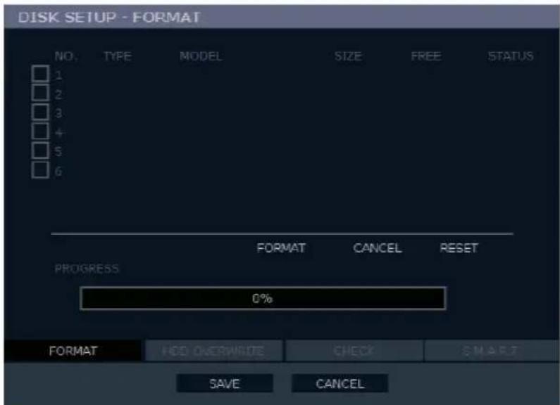
To format a Hard Drive or USB device, select the appropriate device, click FORMAT, and then click YES.
Tip Refer to the list of Approved USB Flash Drives in the Introduction of this manual.
To refresh the list of connected USB devices, click RESET.
Caution All USB devices must be formatted as FAT32 before using with the recorder.
Note When formatting a drive, all video and other data stored on that drive will be permanently erased and cannot be recovered.
Overwrite
Set options for overwriting data when the Hard Disk Drive becomes full.

- Enable HDD OVERWRITE to allow the recorder to write over previously recorded data, starting with the oldest date, when the HDD is full. If set to DISABLE the recorder will not record any new data once the HDD becomes full.
- Enable a DISK FULL WARNING for notification when the HDD becomes full and HDD Overwrite is disabled.
Check
Check the HDD for errors or failure.

SMART Check
S.M.A.R.T. = Self Monitoring Analysis & Reporting Technology. Enable SMART Check to detect signs of HDD failure.
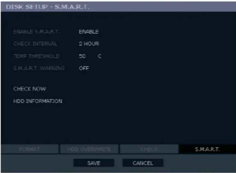
- Set ENABLE S.M.A.R.T. to ENABLE or DISABLE.
- Set a CHECK INTERVAL between 1 and 24 hours.
- Define a TEMP THRESHOLD and select Celsius or Fahrenheit.
Note The recommended upper optimum operating temperature for the HDD is between 104°F to 122°F (40°C to 50°C).
- Select a S.M.A.R.T. WARNING to be activated when the HDD reaches the defined threshold.
- Click SAVE to save your settings.
Tip Select HDD INFORMATION and press ENTER to view the current HDD and USB drive information.
User Setup
Use the User Setup to Add or Delete users.

Adding / Changing a User
To add a new user:
- Click MENU on the hover menu and click SETUP.
- Click SYSTEM, and then click USER SETUP.
- Click ADD/CHANGE.
- Type a USER name.
- Type a PASSWORD and CONFIRM for the new user.
- Select the FUNCTION and SETUP access options for the user.
- Select which cameras will be visible to the user in LIVE and PLAYBACK modes.

SHUT DOWN – Allow the user to shut down or restart the recorder.
EXPORT – Allow the user to perform an export or backup saved data.
USE CD/DVD/USB - Allow the user to use the USB port. This is a server-side feature only.
SEARCH – Allow the user to use the search functions to locate video and access video from the current day using the REPLAY key on the front panel.
EXPORT VIEWER – Allow the user to include a copy of the Backup Viewer application when a local backup is made. This is a server side feature only.
NETWORK CONNECTION – Allow the user to log in using Web Viewer.
PTZ – Allow the user control of any connected PTZ cameras.
HEALTH CHECK – Allow the user to use the Health Check function of SCS to connect to and monitor the recorder.
INSTANT RECORDING – Allow the user to activate the Instant Recording feature.
SETUP ACCESS PERMISSION – Allow the user to access the selected portion of the setup menu.
LIVE & PLAYBACK – Allow the user to view live and recorded data for only the selected cameras.
Configuration
Import and Export current settings. See details in the Save Settings section.
Shutdown
Use Shutdown to safely shutdown the system.
- On the hover menu, click MENU, and then click SETUP.
- Click SYSTEM, and then click SHUTDOWN.
- Click OK.
- Turn the power off when shutdown is complete by unplugging the power adapter cord on the back of the recorder.
Note Improper shut down of the system can cause data loss and system corruption.
CAMERA
Camera Setup

CH – Camera Channels
NAME – Use the on-screen keyboard to enter a camera name [user defined].
HIDDEN - ON/OFF
Note HIDDEN on the CAMERA SETUP page hides cameras from the main monitor (VGA/HDMI/MAIN BNC) when no users are logged in. To hide cameras from users, clear camera check boxes on the SYSTEM > USER SETUP > ADD/CHANGE.
ADJUST – Detailed camera display settings
Color Setup (Adjust)
CAMERA - 1 \~ 16 [camera to apply color settings to]
APPLY ALL – Apply current color settings to all cameras

PTZ Setup

CH – Camera Channels
BAUD RATE – Sets the port information for the connected camera. [Consult the documentation provided by the camera manufacturer to obtain this information.]
ID – Sets the PTZ ID from 1-255
PROTOCOL – Select a PTZ protocol
Spot / Sequence Setup
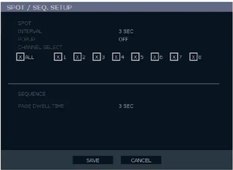
Spot/Sequence Setup allows you to set the parameters for the SPOT OUT on the recorder and the local live view sequencing.
SPOT – Configure the SPOT OUT connection.
INTERVAL - Set the sequence interval time (1 \~ 100 seconds).
POPUP – When enabled, this function interrupts the sequencing when an event occurs, and switches to the event channel (ON / OFF).
CHANNEL SELECT – Select cameras to include in sequence (1\~16, ALL).
SEQUENCE – Configure the appearance of the sequence on the live view screen (VGA/HDMI/MAIN BNC).
PAGE DWELL TIME – Set the sequence interval time for full pages (0 \~ 100 seconds).
Monitor Setup

TRANSPARENCY SETUP – Set the transparency of the setup windows (0 \~ 20).
VGA RESOLUTION – Set monitor resolution.
FIT-IN VGA – Adjusts the display to display properly on a VGA monitor. When FIT-IN VGA is not selected, the display is adjusted to display on a monitor connected to the TV Out BNC output.
OSD – Select the items to display on the screen (DATE, TIME, TITLE, PTZ, RECORD, AUDIO).
Recording Setup
Frame
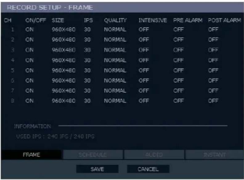
ON/OFF – Enable or disable recording on individual camera channels.
SIZE - Choose the recording resolutions (352×240 / 704×240 / 704×480 / 960×480).
IPS – Choose the recording rate (1\~30 Images Per Second).
QUALITY – Choose the image quality (LOW / NORMAL / HIGH / HIGHEST).
INTENSIVE – Enable Intensive Recording to be triggered on a sensor or motion event (ON/OFF).
Note
When a motion or sensor event occurs, INTENSIVE RECORDING automatically increases the recording rate to the maximum IPS that is available (based on your current recording configuration frame rate) up to 30 IPS per channel. If events occur on multiple channels with intensive recording enabled, the available IPS is evenly distributed across those channels.
PRE ALARM – Set the Pre-Alarm recording time (0\~5 seconds).
POST ALARM – Set the Post-Alarm recording time (0\~30 seconds).
USED IPS – This displays the images per second (IPS) currently used, and the total available IPS.
Schedule
Set the recording schedule for each camera:
- On the hover menu, click MENU, and then click SETUP.
- Click RECORD, and then click SCHEDULE.
- Select a camera to create a recording schedule, or select ALL.
- Select your desired RECORD MODE.
- Click hour block or the day of the week to set the entire day.

NO RECORDING
No recording.
No Color
Even if you set recording frames and select ON in RECORD > CAMERA, the recorder will not record anything if you select OFF in RECORD > SCHEDULE.
CONTINUOUS
Continuous recording.
Yellow
MOTION
MOTION-detection recording.
Green
In this mode, the unit records only when motion is detected in the motion area, and stops recording when motion is not detected. Adjust motion area settings in RECORD > MOTION/EVENT SETUP > INPUT.
If you set motion to OFF in RECORD > MOTION /EVENT CONFIGURATION and set CONT + MOT in SETUP > RECORD > SCHEDULE the recorder will NOT record when motion is detected.
| SENSOR | Sensor-activated recording. |
| Orange | In sensor mode, the unit will record when a sensor is triggered - during DURATION time as set in RECORD > MOTION /EVENT CONFIGURATION > ACTION. |
| CONT+MOT | Continuous and motion detection recording |
| Sky Blue | The unit records in CONTINUOUS mode but switches to MOTION when motion is detected in the motion area. The recorder also will log a Motion Event and send the event to the Remote Monitoring software.If you set motion to OFF in RECORD > MOTION /EVENT CONFIGURATION and set CONT + MOT in SETUP > RECORD > SCHEDULE the recorder will NOT record when motion is detected. |
| CONT+SENS | Continuous and sensor-activated recording |
| Brown | In this mode, the unit records continuously and switches to SENSOR recording mode when a sensor is triggered. The recorder also will log a Sensor Event and send the event to the Remote Monitoring software. |
| MOT+SENS | Motion detection and sensor-activated recording. |
| Lilac | The recorder will only record when motion is detected or a sensor is triggered. |
Holiday Setup
Add a recording schedule for a specific date in HOLIDAY SETUP. You can add up to 32 individual holiday recording schedules. To add a new HOLIDAY schedule:
- On the hover menu, click MENU, and then click SETUP.
- Click RECORD, and then click RECORD SETUP.
- Click SCHEDULE.
- Create a recording schedule in the H.DAY row.
- Click HOLIDAY SETUP.
- Click the DATE, and set your desired holiday date using the on-screen calendar.
- Click the DESCRIPTION column to type a description or name for this holiday.
- Click ADD to add the holiday.
Audio

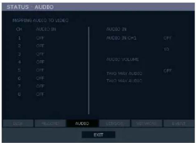
MAPPING AUDIO TO VIDEO – Associate cameras to the appropriate audio channel.
AUDIO IN – Enable or disable each audio channel for recording (ON / OFF).
AUDIO VOLUME – Set audio volume (1\~15).
TWO WAY AUDIO – Enable or disable two-way audio (ON / OFF).
Emergency Recording
Configure the recording settings for Emergency Recording and Instant Backup to use when they are activated.
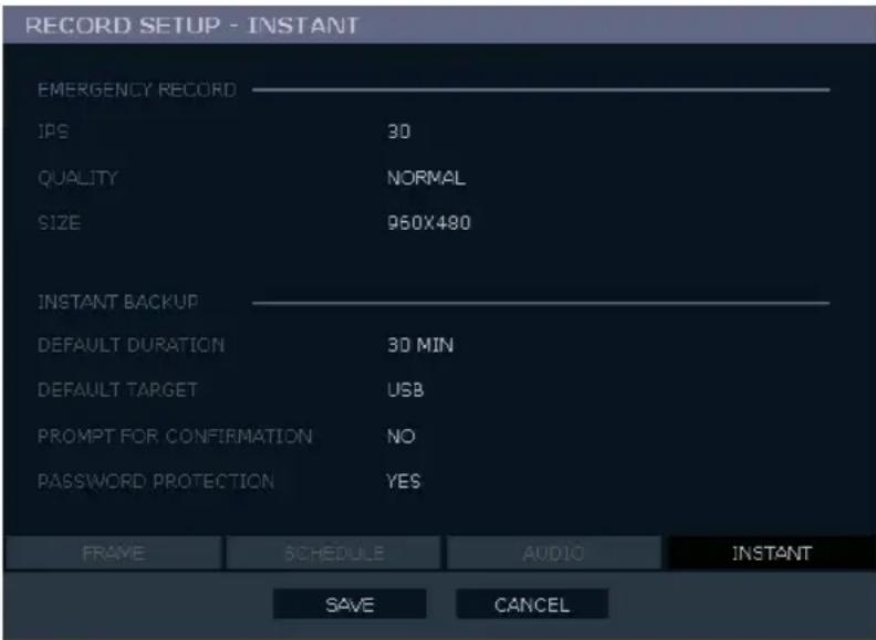
Emergency Record:
IPS - Set the recording rate per camera (in Images Per Second).
QUALITY – Set the picture quality (affects file size).
SIZE – Set the resolution of the video image.
Instant Backup:
Note Instant Backup functions are only available on EAV Max recorders. The EAV does not support Instant Backup.
Using Emergency Recording
To activate Emergency Recording on the recorder:
- Press the REC key on the front panel of the 16ch model, or click the Emergency Recording button on the hover menu.
The E-REC recording icon will appear in the lower right corner of the screen.
To cancel Emergency Recording:
- Press the REC key on the front panel of the 16ch model, or click Emergency Recording on the hover menu.
The recorder will resume scheduled recording.
Motion/Event Setup
Motion / Event Setup has four sections; Input, Sensor, Action, and Alarm Monitor. When an event occurs (Input), the unit records the image according to its settings (Camera Setup) and triggers an alarm (Action).
Input

CH – Channels 1-8 will appear by default. To view channels 9-16, click CH.
MOTION – Enable or disable motion input (ON / OFF).
SENSITIVITY - 1\~10 (1 = least sensitive, 10 = most sensitive)
AREA – Define the motion detection area.
SENSOR – Associate a sensor with the camera channel.
VIDEO LOSS – Associate a channel to monitor for video loss detection.
Setting Up Motion Detection Recording

To record data only when motion is detected:
- On the hover menu, click MENU, and then click SETUP.
- Click RECORD, and then click MOTION/EVENT SETUP.
- Set MOTION to ON.
- Set the motion SENSITIVITY level. [1\~10].
- To set a global motion area (each channel can also be configured individually), click AREA.
- Use the mouse to select or clear squares on the grid:
a) Right click the screen, and then click CLEAR ALL.
b) Click the squares to include in the motion grid.
c) Right-click again, and then click SAVE AND EXIT to save the selected motion grid.
-
Repeat as necessary for each camera channel.
-
When motion area setup is complete select SAVE to save settings and exit setup.
Sensor

Sensor Setup
- Set the Sensor TYPE to N/O (Normally Open) or N/C (Normally Closed).
- Repeat for all sensors.
- Click SAVE.
Alarm Setup
- Enable or disable the SIGNAL (ON / OFF).
- Set each alarm TYPE (NO / NC).
- Repeat for all relays.
- Click SAVE.
Power Off
The POWER OFF option is a preset function that triggers an alarm relay when the recorder loses power. This function is preconfigured to set alarm relay No. 1 to ON and N/C. When a power loss occurs, alarm relay No. 4 will open. When power is restored the alarm will close.
S.M.A.R.T. Alarm
The S.M.A.R.T. ALARM option is a preset function that triggers an alarm relay when the HDD exceeds the temperature threshold configured on the SYSTEM > DISK SETUP > S.M.A.R.T. page. This function is preconfigured to set an alarm relay to ON and N/C. When the HDD exceeds the temperature threshold, the alarm relay will open. When the temperature is at a safe level again the alarm will close.
Note
SET and CLEAR are used to test the alarm relay operation. SET is used to manually activate all relays that are set to ON. CLEAR is used to manually deactivate all relays.
Hold Video Loss
When set, the alarm will stay on when a channel loses video. The alarm will turn off when Video returns.
Action

CH – Channels 1-8 will appear by default. To view channels 9-16, click CH.
Alarm - Associate an alarm relay with a camera channel (OFF / 1).
Delay - Set the delay time for relay to activate (0\~100 seconds).
Duration - Set the duration of the alarm relay (0\~100 seconds).
Preset – Enable a PTZ camera to move to a preset position when an event occurs (0\~100). See PTZ Control for more information.]
Notify – Select the type of alarm to associate with this event (BUZZER / POPUP).
Alarm Monitor
Send event information to a remote client using the Alarm Monitor software.
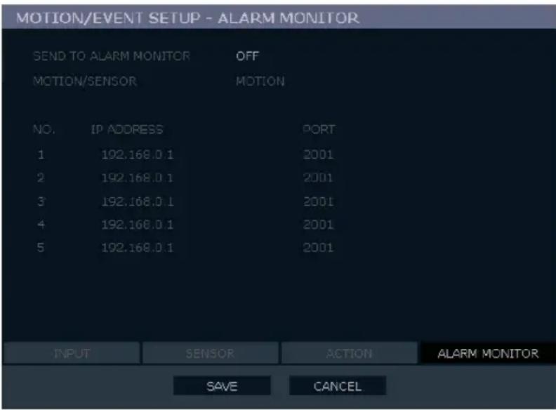
- Set SEND TO ALARM MONITOR to ON.
- Select the types of events to send to the Emergency Agent (MOTION, SENSOR, MOTION + SENSOR).
- Type the IP ADDRESS of the remote client.
- Type the PORT number.
Note
The port number selected is the port that Alarm Monitor uses on the remote PC. The port shown in this screen must match the port shown in Emergency Agent or SCS and the port must be open on the remote PC.
Network Setup
Configure network settings.

Network
HOST NAME – Host name for the recorder on the network.
NETWORK TYPE – Select STATIC IP to manually define a static IP address. Select DHCP for a DHCP server to assign an IP address automatically. Contact your network administrator for more information.
IP ADDRESS – You can set the IP ADDRESS if your network type is set to STATIC. Contact your network administrator for this information.
CLIENT CONFIGURATION – Set up the connection ports and Max transfer speed for remote connections.
CENTER PORT – EAV recorders use the Center port and the primary communication port to create remote connections. This port must be the same as the port setting on the remote PC.
VIDEO PORT –EAV recorders use multiple ports to create remote connections. The remote port is user-defined (default 2000), and a secondary port is automatically assigned (default 2002). The recorder assigns the secondary port based on the remote port, in increments of two. (For example, if you set the remote port to 2222, then the secondary port will be 2224.) Verify that all these ports are available when setting up Network Address Translation (NAT) or firewall.
WEB PORT – Defines the port that Internet Explorer uses to connect over the web and view video. If this port is changed then the new port must be defined when attempting to web connect. (For example, if your IP address is 10.0.0.5 and you change the web port to 800, then you must type http://10.0.0.5:800 in your browser.)
MAX TRANSFER SPEED – Set network bandwidth. This feature is used for slower internet connections to throttle the amount of data the recorder sends across the network at a time.
Network Setup continued
DDNS - Dynamic Domain Name Service (DDNS) is a service that allows a connection to an IP address using a hostname (URL) address instead of a numeric IP address. Most Internet Service Providers use Dynamic IP Addressing that frequently changes the public IP address of your internet connection; this means that remote connections through SCS and Remote would require frequent updates. DDNS automatically redirects traffic to your current IP address when using the hostname address (i.e. oe123456.Toshibadvr.com).
DDNS SERVER – The current DDNS server.
HOST NAME – Hostname for the DDNS server account.
ID – Username for the DDNS server account.
PASSWORD – Password for the DDNS server account.
STATUS – Checks DDNS settings by attempting to communicate with the DDNS Server.
Serial Setup
Configure connected serial devices.

Note: EAV recorders do not have an RS-232 port for connecting serial devices.
TYPE - NONE / EXTERNAL CONTROLLER
MODEL – Select appropriate model.
Port Information
BAUD RATE / DATA BIT / PARITY / STOP BIT
E-mail Setup
The recorder can send an e-mail notification to up to six defined e-mail addresses when an event happens.

E-MAIL SERVER – Configure the recorder to use selected e-mail server (DVR / SMTP).
OPTION – Define the type of event that will trigger an e-mail notification.
MOTION – After a motion alarm is triggered.
SENSOR – After a sensor alarm is triggered.
VIDEO LOSS – After video loss on a camera
POWER – When the recorder is shut down and restarted.
SETUP – When a user accesses Setup.
LOG IN – When a user logs in.
LOGIN FAIL – After one failed login attempt.
DISK FULL – When the HDD reaches the user-defined maximum disk full percentage. See DISK MANAGEMENT – OVERWRITE.
S.M.A.R.T. – When the HDD reaches the user-defined maximum temperature. See DISK MANAGEMENT – S.M.A.R.T..
PIC - ON / OFF [Enable to send a picture of the event.]
E-MAIL ADDRESS – Enter the e-mail address.
MySurveillix
To enable MySurveillix on your recorder during the initial configuration:
1. Click ENABLE MYSURVEILLIX NOW.
Note To enable MySurveillix at any time after the initial configuration, go to NETWORK > MYSURVEILLIX SETUP and then set ENABLE MYSURVEILLIX to ON.

- Log in using the admin user account. (default username: admin, password: 1234)
- Set the CUSTOM DAY/NIGHT TIME.
- Click SEND to send a test report to MySurveillix.
- To send Alarm Events to MySurveillix, set SEND ALARM EVENTS INSTANTLY to ON.
- To send active updates to MySurveillix every 5 minutes, set HEARTBEAT to ON.
- Click SAVE to save your settings.

System Log View
Displays system log information. System Log View displays the recent activity of all users on the recorder. You can export and save the System Log to review user activity.

Version View
Displays system information and software version information for the recorder.

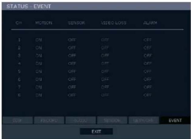
Status View
Displays status screens for:
Disk

Record

Audio
Status View continued
Sensor

Network
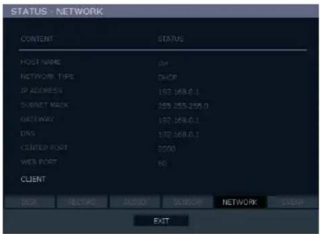
Event
Notes:
The LOG-IN window will display on the monitor until a user logs in with the correct ID and password.
Tip To prevent unauthorized changes to the system settings, the administrator should change the default administrator password and create a User account.
Default Administrator Log In
The default administrator account login is:
USER: admin
PASSWORD: 1234
LIVE DISPLAY MODE
Channel Selection
A live image can be selected by pressing corresponding number key on the front panel of the recorder.
The images can be seen in real-time in the configuration of 1, 4, 9, 16 channels screen. To toggle through the viewing options press LIVE on the recorder.


natural_image
Simple geometric grid with four equal squares (no text or symbols)To select a channel using a mouse, double-click the video image. To return to a previous screen mode after selecting a viewing channel, double-click again.
Icons
In Live mode, icons or messages on the screen indicate the system mode or status.
Right-upper corner on each CH. Right-bottom corner on full screen.
| C | Continuous Recording | ∅HDD | No HDD, Smart Alarm & HDD Failure |
| M | Motion Detection Recording | E-REC | Using Emergency Recording |
| S | Sensor Activated Recording | PTZ | Using PTZ |
| C+M | Continuous + Motion Alarm Recording | CHECK FAN | Warning for exceeding temperature |
| C+S | Continuous + Sensor Activated Recording | SEQ | Showing sequence mode |
| M+S | Motion Detection + Sensor Activated Recording | ZOOM | Showing digital zoom mode |
| C | Emergency Recording | ||
| Sensor Activated | |||
| Motion Detected | |||
| Audio Channel | |||
| PTZ | PTZ Camera |
Mouse-Over Menu
Move the mouse to the bottom of the monitor in live mode. The hover menu will appear.


Sequence - Click to start camera sequence.

Emergency Recording – Click to start instant recording. In instant recording mode, the system records all channels at the recording rate configured on the Emergency Recording screen.

PTZ Mode – Click to enter PTZ mode. In PTZ mode, you can pan/tilt and zoom by moving the mouse pointer, referred to as a virtual joystick.

Quick Search – Click to automatically play back the most recent video clip.

Dock Tool Menu – Click to dock the Tool menu at the bottom of the screen. If the Tool menu is not docked, it will be shown only when you place the mouse pointer in the lower portion of the screen.
Note
If there is no icon in the right upper corner of the live screen mode, it means that the system is not currently recording. If this is the case, you should check the recording schedule or camera setup in the main setup menu.
Instant Recording
The front panel of the 16ch model and hover bar has an Instant Recording button. Press the button to instantly start recording all the channels at the recording rate configured in Emergency Record setup. All the channels, regardless of recording mode & recording on/off, will record.

will show in live mode and a red bar represents Instant Recording video in the search bar.
Popup Menu
Right-click the live screen to open the Popup Menu.
HIDE LIVE VIEW – Hide the selected camera from Live view.
RECORD CHANGE – Change the recording settings for that channel including PPS, quality, resolution and event response.
PAGE SEQUENCE – The SEQ icon appears on the bottom right of the screen and displayed channels will be sequentially changed.
FREEZE ALL – Pause all channels displayed on-screen.
AUDIO – Select an audio channel to play on attached speakers.
LOGOFF – Select to log out the active user.
SEARCH – Open the Search Menu.
INSTANT BACKUP – Backup direction to connected USB drive.
PTZ – Switch to PTZ mode.
SETUP – Open the Setup Menu.

No Signal
If no camera is connected to a channel, NO SIGNAL appears on the display screen. When a camera is disconnected, the recorder will generate a warning sound according to the system settings.
No Permission
The Administrator can set different levels of authorization for each user. If a user does not have permission to view a particular live or playback channel, that channel will appear black in live and playback mode. If a user attempts to access a restricted function, a NO PERMISSION warning is displayed.
PTZ
To enter PTZ mode:
• Right-click the Live screen and select PTZ on the pop-up menu.
OR
- Click the PTZ icon on the hover menu.
Drag the mouse up/down or left/right to move pan/tilt position of the camera. As you move the mouse away from the center of the screen, the camera movement speed increases. You can also zoom-in/out by using the scroll wheel on the mouse.
Note Full PTZ functions are available using the front panel buttons, a mouse, or a keyboard controller.
PTZ Popup Menu
Right-click the desired camera to open the PTZ Popup menu while in PTZ mode.
M Access the camera OSD menu.
ZOOM Zoom in/out on PTZ camera. Enabled by default in PTZ mode.
FOCUS Adjust focus on PTZ camera.
IRIS Adjust the iris on PTZ camera.
PRESET Go to preset position. Select the preset number. The maximum preset number is 255.
PRESET TOUR Start preset tour. PRESET TOUR will sequence though all preset positions. Can only be enabled while in full screen mode.

Create PTZ Preset Position
- Right-click your desired PTZ camera to open the PTZ Popup menu while in PTZ mode.
- Select a PTZ Preset ID number.
- Click MOVE under PRESET to move the camera to the desired position.
- Click SET to save the preset position.
Searching Recorded Data
Search recorded video on the recorder to find a specific time or event.
- On the hover menu, click MENU, and then click SEARCH.
- Select your TARGET media (HDD / USB).
- Select your desired search method.
Quick Search
- On the hover menu, click ▶ to automatically playback the latest video clip.
- Using the playback control icons, you can search recordings and control the speed of the forward or backward playback (2x, 4x, 8x, 16x, 32x).
Graphic Search
In the search mode, move the mouse to the bottom of the screen and click the colored time bar to search the desired section of recorded video.
- The white-vertical line indicates the current search time.
• The colors of the time bar are different according to the recording method selected.
Yellow – Continuous recording
Green – Motion-detection recording
Orange – Sensor-activated recording
Sky Blue – Continuous + Motion detection recording
Dark orange – Continuous + Sensor-activated recording
Pink – Motion detection + Sensor-activated recording
Red – Emergency Recording
Dark Blue – Data recorded during DST (Daylight Saving Time)

Quick Backup in Search Mode
You can easily archive video while watching a video playback.
Note: The Quick Backup is only available using the BACKUP button, provided on the 16 CH EAV recorder.
In the search mode:
- Press the BACKUP on the front panel to set the Start time. You will see S [Date/Time of clip] in right bottom of the playback monitor.
- Continue video playback until you reach the end of the desired clip.
- Press the BACKUP again to set the end time. The backup menu will open and you can select the backup media (USB thumb drive) and complete the backup.
Express Search
Select a specific date and time to search for recordings:
- On the hover menu, click MENU, and then click SEARCH.
- Click EXPRESS SEARCH.
-
Click a date on the list.
-
Click the appropriate set of channels and then move the white vertical line indicator to select a specific time for searching.
Tip Dates with an asterisk contain recorded video data.
- Click PLAY.
- Use the playback controls to view the video.
Event Search
Use the Event Search to find particular events.
The 11 most recent events display on the first Event Search/Log page. Click the arrows at the top of the screen to view the remaining entries for each date. You can filter the log results by SENSOR, MOTION, VIDEO LOSS, and DISK FULL.
Write the Event log to a connected USB device in text file format:
- Connect a USB device to the recorder.
- Click SCAN, and then click EXPORT to copy the log information to the USB device.
- The Event Log is saved in a dated folder as a system.log file.
Jump to First Saved Data
Go to the first frame of the recorded data. This is the oldest image recorded.
Jump to Last Saved Data
Go to the last frame of the recorded image. This is the latest image recorded.
Daylight Saving Search
Daylight Saving Search is used to find recorded data after switching the time at the end of Daylight Saving Period. The System will record data with the same time stamp for two hours when they are repeated. If any overlapped time data exists the system will display the times on this page.
Search Popup Menu
Use to access display options in Search Mode.
- Right-click the desired channel to open the Search Popup Menu.
TIME SELECTION – Change the Date/Time to search.
SAVE JPEG – Save a JPEG still image of the current frame.

Note
SAVE JPEG is only available when a single camera is selected. To activate, select a single channel (full screen), pause playback, and press ENTER twice, or right click the channel to open the popup menu.
Manual Export
Back up recorded data on a connected USB device.
Tip Using this export method, video data is saved in a proprietary format and must be viewed using the Export Viewer software.

To configure a data backup:
- Click MENU on the hover menu, and then click BACKUP.
- Connect a USB device.
- Click SCAN to locate the device.
- Select your desired CAMERAs and the FROM and TO time for the backup.
- Click ESTIMATE to display estimated data size and free space available.
- Select EXPORT VIEWER to add the Export Viewer to the backup file.
- Click EXPORT.
Caution Refer to the USB Flash Drive Approved List in the Introduction chapter. If you are using a new USB device to back up your data, you must format it first as FAT32.
Note Click ESTIMATE before clicking EXPORT. If any backup parameters are changed (Date, Time, Channels) you must click ESTIMATE again.
Caution Do not shutdown the system during the backup process.
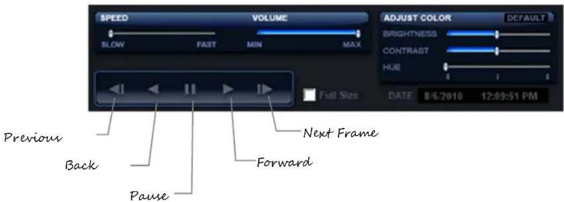
Play recorded video on a PC using Backup Player, the proprietary media player included with every backup file.
![[1] [2] [3] [4] [5] [6] [7] [0] [9] [10] [11] [12] [13] [14] [15] [16] SPEED VOLUME ADJUST COLOR DEFAULT SLOW FAST MIN MAX 0 3 5 9 12 14 18 21 23 BRIGHTNESS CONTRAST HUE DATE 0/6/2010 12:09:51 PM Full Size](/content/2026/05/1001989/images/021f10a2cac502ece39e657e53e886a922da708a80c2ef61a6662e6331281944.jpg)
Controlling Backup Player
Setup and Save Functions
These function buttons allow you to configure the Backup Player and save a JPEG image or AVI video.

OPEN – Allows you to choose which data to open. When selecting data that is saved to your local hard drive, the video must be in a directory named DATA. Navigate to the folder above the DATA directory and click OK to see the available playback options.

SETTINGS – Select Direct Draw De-Interlacing for image viewing. Also allows you to include Image information when exporting a JPEG

EXPORT AVI –To export an AVI file: Click this button, enter the desired Digital Signature, the AVI start time, the AVI end time and to include audio data (if desired) and press OK.

ZOOM – Select this button to turn your cursor into a magnifying glass and click the desired camera image to zoom in.

EXPORT JPEG – To save a JPEG: Click this button, enter the desired Digital Signature and click OK, then browse to the desired save location.

PRINT – Opens the print window on your computer.
Play Back Backup Image
Play recorded video on a PC using the proprietary media player included with every backup file.
- Connect your USB device to the PC.
- Navigate to the files on the USB drive.
- Double-click the MultiBackupPlayer application.
- Click the Open Video File icon and select the file to view from the desired date folder.
Screen Division Buttons
The Screen Division buttons allows you to view cameras in groups such as two by two, three by three and four by four. The button options are shown below.

Single Channel View – Displays one camera channel. To return to a different Multi-Camera View, select a different Screen Division button.

Four Channel View – Displays cameras 1-4 in the Video Display Area. Click the button again to rotate to cameras 5-8, 9-12, etc. To return to a different Multi-Camera View, select a different Screen Division button.

Nine Channel View – Displays cameras 1-9 in the Video Display Area. Click the button again to rotate to cameras 9-16. To return to a different Multi-Camera View, select a different Screen Division button.

16 Channel View – Displays cameras 1-16 in the Video Display Area. To return to a different Multi-Camera View, select a different Screen Division button.
UPGRADE FIRMWARE AT THE RECORDER
Obtain the latest software release and save the file to a USB device. Please check the product web site at www.Toshiba.net or contact Technical Support for the latest software. See the back cover of this manual for contact information.
- Insert a USB drive with the update files.
- Click SYSTEM, and then click SYSTEM SETUP.
- Click S/W UPGRADE.
- Select the media type (USB HDD/STICK).
- Click SCAN.
-
Click OK to start the upgrade.
-
On the hover menu, click MENU, and then click SETUP.
Use the System Setup menu to export and import saved or factory default system settings.

Save Settings
- On the hover menu, click MENU, and then click SETUP.
- Click SYSTEM, and then click CONFIGURATION.
- Select an empty PROFILE and define a name for the settings configuration.
- To save settings to a USB device, click EXPORT.
- Click SAVE and confirm to continue the export process.
Import Settings
- On the hover menu, click MENU, and then click SETUP.
- Click SYSTEMS, and then click CONFIGURATION.
- Select a previously saved PROFILE, and then click LOAD.
- To import a profile saved on a USB device, click IMPORT.
- Click OK to complete the import process.
REMOTE SOFTWARE
SCS OVERVIEW
SCS is Video Management Software from Toshiba that allows you to access your recorder from any PC or laptop with a network connection.
Use SCS to monitor live video, search recorded video, control PTZ cameras, export video, and even search live video as it happens.
For complete instructions regarding the use of SCS VMS software, please refer to the SCS user manual.
To install SCS on your PC, follow these instructions:
- Locate the Software CD included with your EAV recorder, and make sure that the PC is turned on.
- Insert the Software CD into the CD drive.
- Click Start > My Computer – or – double-click the My Computer icon on your desktop.
- Locate the CD drive and double-click to display contents of the CD-ROM.
- Double-click SCS.exe – or – right-click SCS.exe then click Open.
- Click on Install SCS from the on-screen menu.
- Follow the on-screen instructions for installing the software.
- The Setup process will notify you when SCS is installed. Click Finish to complete Setup and close the installer window.
The recorder allows access to the video using Microsoft® Internet Explorer® browser versions 6 and above.
To log in to the recorder server from the Web Viewer, a user account must be made for the user. This ensures that only authorized users are allowed to log in. In addition, each user can be assigned different privileges that allow or deny access to different functions.

Search Open the Search screen.
PAN/TILT Open the PTZ controller.
Export Image Save JPG file of selected image.
Print Print selected image on connected printer.
Connect Connect to a Toshiba recorder.
Connecting to a Recorder Using Web Viewer
- Open Microsoft Internet Explorer.
- Enter the IP address of the recorder into the Address bar.
- When attempting this for the first time you will be asked to accept an Active X installation. Click Yes.
Note
If you receive a message saying Internet Explorer security settings do not allow you to download Active X components then you will need to adjust the browser security settings. Add the IP address of the recorder to the trusted sites list inside Internet Explorer settings. Contact the System administrator for additional help with adjusting Internet Explorer settings.
- Type the User ID and Password of an authorized user.
- Click Connect. The cameras will display.
Search Video Using Web Viewer

Performing a Basic Search
- Click the Calendar icon to open the calendar and select a date.
- Select a time using the hour and minute control bars.
- Select one or more cameras.
- Click Play. (Video can be played forwards, backwards, or frame-by-frame.)
Status Search
The Status Search option displays a timeline in graph format. Scroll through multiple cameras and easily locate hours with recorded video.

Performing a Status Search
- In Search mode, click Status.
- Click Date to open the calendar and select a date.
- Click along the orange recorded video block to select a desired camera or time frame.
- After locating the desired video, close the Status Search window and use the playback controls to play forward, reverse or frame-by-frame.
Clean Image
EAV recorders can record video using one of three different resolutions. When using the 704 x 480 resolution, two fields are mixed. Because of the timing gap between the two fields, according to the standardized image rules, after image might occur to high speed moving images. The recorder allows the user to remove this by clicking Clean Image.
- Use the Search screen to locate the desired frame. Double-click the image.
Note Only one camera can be selected at a time for this function to work.
- Click Print. The Print Options window opens. Depending on the printer being used, there may be several printing options available. Refer to the printer manual for more information.
- Click Print to print the selected images.
Note The message "NO DEFAULT PRINTERS INSTALLED" will display if no printer is installed.
Save
Using the Toshiba Web Viewer, you can export single images in the Image file formats and save video clips in an .AVI format. Both .JPG and .AVI file formats are the most commonly used graphical formats today. Virtually every computer offers some type of support for these file formats which make them the most ideal formats to use.
JPEG
Optimized for compressing full-color or grayscale photographic images, JPEG images are 24-bit (16.7 million color) graphics. Use JPEG to export a single image or frame.
AVI
AVI image data can be stored uncompressed, but it is typically compressed using a Windows-supplied or third party compression and decompression module called a codec. AVI is used to export a video clip.
- From the Search screen, click Save.
- Select the export type, JPEG or AVI.
Note Different image format types provide different file-sizes, quality and compatibility.
- Select Mark Digital Signature if desired.
AVI File
a) Select a compression Codec. Each codec provides different levels of quality, compatibility and file-size.
b) Enter the Time to Save (seconds) to record. Although 50 is the longest time displayed, a longer recording may be entered manually.
c) Select Quality - 50 \~ 100. When size is not an issue, set quality to 100.
- Click Next to select a save location to save file.
- Click Next to start exporting the file. The Cancel button exits the window without exporting file.
JPG images and AVI video files that are exported from the recorder are automatically embedded with a digital signature. Digital signatures are a way to verify the authenticity of the images to ensure that they have not been tampered with or edited in any way. Included on the Software Installation DVD, supplied with the recorder, is the Digital Signature Verification program. This program can be installed on any Windows XP, Windows Vista or Windows 7 computer.
Using the Digital Verifier
- Open the Digital Verification program by selecting Start > Programs > Toshiba > Digital Verifier > Digital Signature Verifier.
- Click the Browse button to load the JPG image.
- Enter the Site Code of the recorder that the image was originally extracted from. (The Site Code is specified in the System Setup menu)
- Click Verify to continue or Close to close the window without verifying.
If the image has not been tampered with, a blue square will appear around the image with the message "Original image file."

If the image has been tampered with, a red square will appear around the image with the message “Entire image changed or wrong SITE CODE.”

LED Status Indicators
16 Channel

Power Illuminates when power is supplied to the recorder.
Record Flashes when the hard drive is being accessed.
Network Illuminates when the recorder is connected to a network.
Function Buttons
16 Channel
| SETUP | Setup | Open the setup menu. |
| SEARCH | Search | Open the search menu. |
| LIVE | Live | Change the display mode. Display switches in the following order when the LIVE key is pressed successively: (Single >4 >7 >9 >10 >13 >16 > Single >4 >7 >9 ...split screen mode). |
| PTZ | PTZ | In the Live view, press to enter PTZ mode. |
| EXIT | Exit | Exit the current menu / function. |
| REC | Record | Start Emergency Recording when viewing live video. |
| BACKUP | Backup | In live mode, press to open the backup menu.For Quick Backup in the search mode:Press once, to set the start time.Press again, to set the end time.Press a third time, to complete Backup. |
| ◄/◄◄ | Search | Start reverse playback of recordings. Press successively to change the fast reverse speed. |
| ►/■ | Replay | Start playback of the most recent recording. |
| ►/► | Search | Press to Pause or Play in Search mode. |
| Search | Start playback of recordings. Press successively to change the fast forward speed. |
16 Channel Buttons (continued)


| Enter | Input data, make selections, and open pop-up menus. |
| Navigation | Move up. |
| PTZ | Move the camera view point up. |
| Navigation | Move to the right. |
| PTZ | Move the camera view point to the right. |
| Search | Play recorded videos. When pressed successively, the search jumps forward in time by 30 minute increments. |
| Search-Pause | Step forward one frame. |
| Navigation | Move down. |
| PTZ | Move the camera view point down. |
| Navigation | Move to the left. |
| PTZ | Move camera's view point to the left. |
| Search | Play recorded videos in reverse. When pressed successively, the search jumps back in time by 30 minute increments. |
| Search-Pause | Step backwards. |
| Model | EAV16-480 |
| Camera Channels | 16 |
| Looping Outputs | No |
| Max IPS Per Channel | 30 |
| Recording Rate (IPS) | 240 |
| Live Display Rate (IPS) | 240+ |
| Audio Channels | 1 |
| Video Outputs | 1 VGA, 1 HDMI, 1 Spot Out/TV Out (BNC) |
| Digital Relay Outputs | 1 |
| Alarm Sensor Inputs | 4 |
| Image Compression | H.264 |
| Recording Resolutions | CIF (352x240), 2CIF (704x240), HD1 (720x240), D1 (704x480), 960H (960x480) |
| Video Signal Loss Detection | Yes |
| Motion Detection | Adjustable sensitivity, Custom grid |
| Remote Operation | Live View, Setup, PTZ, Firmware update (Remote and SCS only) |
| Remote Software | Toshiba Remote, SCS, Web Viewer (Active X) |
| PTZ Control | RS-485 |
| Recording Mode | Schedules for Continuous, Motion, Sensor, Pre- and Post-Alarm Recording, Instant, Quick Global Setup |
| Playback Search | Multi-channel playback, Calendar and Timeline Search, Event and System Search, First and Last Search |
| Backup | USB, Network |
| Digital Signature Support | Digital Signature Support on AVI and JPG |
| Dynamic DNS | Free for life of product |
| Operating System | Linux® Embedded |
| Storage (Size) | Up to 8TB |
| External Storage Options | N/A |
| Dimensions | W: 14.17" (360 mm) D: 14.96" (380 mm) H: 2.6" (66 mm) |
| Warranty | 3 years / 1 year advance replacement |
www.toshibasecurity.com
1-877-855-1349
© 2014 Toshiba
All rights reserved. No part of this publication may be reproduced by any means without written permission from Toshiba. The information in this publication is believed to be accurate in all respects. However, Toshiba cannot assume responsibility for any consequences resulting from the use thereof. The information contained herein is subject to change without notice. Revisions or new editions to this publication may be issued to incorporate such changes.

- NOTES ON HANDLING
- NOTES ON LOCATING
- NOTES ON CLEANING
- NOTES ON MAINTENANCE
- NOTES ON MOISTURE CONDENSATION
- Do not use the recorder when moisture condensation may occur.
- WARNING
- EXPLANATION OF GRAPHICAL SYMBOLS
- FCC STATEMENT
- EN 55022 Class A Notice
- LIMITED WARRANTY
- Step-by-step Procedures – How to Obtain Warranty Service
- www.toshibasecurity.com
- Critical Use Disclaimer
- Your Responsibilities
- TABLE OF CONTENTS
- Introduction....14
- Installation....18
- Setup 24
- Remote Software 68
- Appendix 74
- INTRODUCTION
- PRODUCT DESCRIPTION
- USB FLASH DRIVE APPROVED LIST
- LOGGING IN FOR THE FIRST TIME
- INSTALLATION
- FRONT PANEL CONTROLS
- Channel
- Connecting the Monitor
- Video Inputs
- Connecting to a Network
- Connecting Audio
- Connecting a PTZ Camera
- Connecting to a Sensor Input
- Sensor In
- Connecting to a Relay Output
- Alarm Out
- Using the Front Panel to Turn On/Off the Recorder
- SETUP
- SETUP MENUS
- Note
- System Setup
- System Setup Continued
- Upgrade Firmware
- Disk Setup
- Format
- Overwrite
- Check
- SMART Check
- User Setup
- Adding / Changing a User
- Configuration
- Shutdown
- CAMERA
- Camera Setup
- Color Setup (Adjust)
- PTZ Setup
- Spot / Sequence Setup
- Monitor Setup
- Recording Setup
- Frame
- Schedule
- NO RECORDING
- CONTINUOUS
- MOTION
- Holiday Setup
- Audio
- Emergency Recording
- Using Emergency Recording
- Motion/Event Setup
- Input
- Setting Up Motion Detection Recording
- Sensor
- Sensor Setup
- Alarm Setup
- Power Off
- S.M.A.R.T. Alarm
- Hold Video Loss
- Action
- Alarm Monitor
- Network Setup
- Network Setup continued
- Serial Setup
- E-mail Setup
- MySurveillix
- Click ENABLE MYSURVEILLIX NOW.
- System Log View
- Version View
- Status View
- Status View continued
- Default Administrator Log In
- LIVE DISPLAY MODE
- Channel Selection
- Icons
- Mouse-Over Menu
- Instant Recording
- Popup Menu
- No Signal
- No Permission
- PTZ
- OR
- PTZ Popup Menu
- Create PTZ Preset Position
- Searching Recorded Data
- Quick Search
- Graphic Search
- Quick Backup in Search Mode
- Express Search
- Event Search
- Jump to First Saved Data
- Jump to Last Saved Data
- Daylight Saving Search
- Search Popup Menu
- Manual Export
- Controlling Backup Player
- Setup and Save Functions
- Play Back Backup Image
- Screen Division Buttons
- UPGRADE FIRMWARE AT THE RECORDER
- Save Settings
- Import Settings
- REMOTE SOFTWARE
- SCS OVERVIEW
- Connecting to a Recorder Using Web Viewer
- Search Video Using Web Viewer
- Performing a Basic Search
- Status Search
- Performing a Status Search
- Clean Image
- Save
- JPEG
- AVI
- AVI File
- Using the Digital Verifier
- LED Status Indicators
- Function Buttons
- Channel Buttons (continued)
Brand : TOSHIBA
Model : Surveillix EAV16
Category : Surveillance Camera