
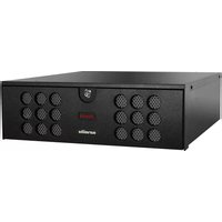
Surveillix DVse8 - Surveillance Camera TOSHIBA - Free user manual and instructions
Find the device manual for free Surveillix DVse8 TOSHIBA in PDF.


| Product Type | Digital Video Recorder (DVR) |
| Brand | Toshiba |
| Model | Surveillix DVse8 |
| Video Inputs | 8 Channels (BNC connectors) |
| Recording Resolution | NTSC: 720x480 / 720x240 / 360x240; PAL: 720x576 / 720x288 / 360x288 |
| Storage Capacity | Up to 8 TB internal (hard drive array) |
| Operating System | Microsoft Windows 7 Embedded |
| Power Supply | 100-240V AC, 50/60 Hz (grounded) |
| Rack Mount | Yes (rack mount kit included) |
| PTZ Control | Yes (RS-485/422 via internal adapter) |
| Network | Ethernet, remote access via DSL/Cable/ISDN |
| Audio Inputs | Up to 16 (8-channel audio input cable included) |
| Sensor Inputs | Up to 16 (normally open/closed, no power supplied) |
| Control Outputs | Up to 16 (relay, Form C, max 24V AC @ 1A) |
| Looping Outputs | Up to 16 (BNC, with termination dip switches) |
| Composite Outputs | Up to 2 (DVI-I, VGA, HDMI) |
| Video Output | DVI-I to VGA adapter included |
| Recording Modes | Continuous, Motion Detection, Alarm, Pre-Alarm, Scheduled |
| Security Access | Multiple levels, user management |
| Warranty | 2 years limited (labor and parts) |
Frequently Asked Questions - Surveillix DVse8 TOSHIBA
User questions about Surveillix DVse8 TOSHIBA
0 question about this device. Answer the ones you know or ask your own.
Ask a new question about this device
Download the instructions for your Surveillance Camera in PDF format for free! Find your manual Surveillix DVse8 - TOSHIBA and take your electronic device back in hand. On this page are published all the documents necessary for the use of your device. Surveillix DVse8 by TOSHIBA.
USER MANUAL Surveillix DVse8 TOSHIBA
Surveillix™ XVSe / DVSe
Hardware Manual
Manual Edition 30340AF – SEPTEMBER 2011
Printed in USA
No part of this documentation may be reproduced in any means, electronic or mechanical, for any purpose, except as expressed in the Software License Agreement. Toshiba shall not be liable for technical or editorial errors or omissions contained herein. The information in this document is subject to change without notice.
THE INFORMATION IN THIS PUBLICATION IS PROVIDED "AS IS" WITHOUT WARRANTY OF ANY KIND. THE ENTIRE RISK ARISING OUT OF THE USE OF THIS INFORMATION REMAINS WITH RECIPIENT. IN NO EVENT SHALL TOSHIBA BE LIABLE FOR ANY DIRECT, CONSEQUENTIAL, INCIDENTAL, SPECIAL, PUNITIVE, OR OTHER DAMAGES WHATSOEVER (INCLUDING WITHOUT LIMITATION, DAMAGES FOR LOSS OF BUSINESS PROFITS, BUSINESS INTERRUPTION OR LOSS OF BUSINESS INFORMATION), EVEN IF TOSHIBA HAS BEEN ADVISED OF THE POSSIBILITY OF SUCH DAMAGES AND WHETHER IN AN ACTION OR CONTRACT OR TORT, INCLUDING NEGLIGENCE.
This software and documentation are copyrighted. All other rights, including ownership of the software, are reserved to DVR Support Center. TOSHIBA, and Surveillix are registered trademarks of TOSHIBA CORPORATION in the United States and elsewhere; Windows, and Windows 7are registered trademarks of Microsoft Corporation. All other brand and product names are trademarks or registered trademarks of the respective owners.
The following words and symbols mark special messages throughout this guide:
WARNING: Text set off in this manner indicates that failure to follow directions could result in bodily harm or loss of life.
CAUTION: Text set off in this manner indicates that failure to follow directions could result in damage to equipment or loss of information.
The Imaging Systems Division of Toshiba America Information Systems, Inc. ("ISD") makes the following limited warranties. These limited warranties extend to the Original End-User ("You[r]").
Limited Two (2) Year Warranty of Labor and Parts
The Imaging Systems Division of Toshiba America Information Systems warrants this product and parts against defects in material or workmanship for a period of two years from the date of original retail purchase by the end-user. During this period, ISD will repair or replace a defective product or part with a new or refurbished item. The user must deliver the entire product to the Surveillix DVR Repair Facility. The user is responsible for all transportation and insurance charges for the product to the DVR Repair Facility. ISD reserves the right to substitute Factory Refurbished Parts and / or Factory Refurbished Product in place of those in need of repair.
Step-by-step Procedures – How to Obtain Warranty Service
[1] Verify operation of the unit by checking the instruction manual and web site for the latest updates at
www.toshibasecurity.com
[2] If there is a defect in material or workmanship, contact the Surveillix DVR Support Center at (877) 855-1349 [877-855-1-FIX] to speak to a technical support representative and schedule service.
[3] Arrange for delivery of the product to the Surveillix DVR Repair Facility. Products must be insured and securely packed, preferably in the original shipping carton. A letter explaining the defect and a copy of the bill of sale or other proof of purchase must be enclosed with a complete return street address and daytime telephone number. The Tracking Number should also be indicated on your documents. Charges for transportation and insurance must be prepaid by the end-user.
Critical Use Disclaimer
The product is not designed for any “critical applications.” “Critical applications” means life support systems, exhaust or smoke extraction applications, medical applications, commercial aviation, mass transit applications, military applications, homeland security applications, nuclear facilities or systems or any other applications where product failure could lead to injury to persons or loss of life or catastrophic property damage. Accordingly, Toshiba disclaims any and all liability arising out of the use of the product in any critical applications.
Your Responsibilities
The above warranty is subject to the following conditions:
[1] You must retain the bill of sale or provide other proof of purchase.
[2] You must schedule service within thirty days after you discover a defective product or part.
[3] All warranty servicing of this product must be made by the Surveillix DVR Repair Facility.
[4] The warranty extends to defects in material or workmanship as limited above, and not to any products or parts that have been lost or discarded by user. The warranty does not cover damage caused by misuse, accident, improper installation, improper maintenance, or use in violation of instructions furnished by ISD. The warranty does not extend to units which have been altered or modified without authorization of ISD, or to damage to products or parts thereof which have had the serial number removed, altered defaced or rendered illegible.
ALL WARRANTIES IMPLIED BY STATE LAW, INCLUDING THE IMPLIED WARRANTIES OF MERCHANTABILITY AND FITNESS FOR A PARTICULAR PURPOSE, ARE EXPRESSLY LIMITED TO THE DURATION OF THE LIMITED WARRANTIES SET FORTH ABOVE. Some states do not allow limitations on how long an implied warranty lasts, so the above limitation may not apply. WITH THE EXCEPTION OF ANY WARRANTIES IMPLIED BY STATE LAW AS HEREBY LIMITED, THE FOREGOING EXPRESS WARRANTY IS EXCLUSIVE AND IN LIEU OF ALL OTHER WITH RESPECT TO THE REPAIR OR REPLACEMENT OF ANY PRODUCTS OR PARTS. IN NO EVENT SHALL ISD BE LIABLE FOR CONSEQUENTIAL OR INCIDENTAL DAMAGES. Some states do not allow the exclusion or limitation of incidental or consequential damages so the above limitation may not apply.
No person, agent, distributor, dealer, service station or company is authorized to change, modify or extend the terms of these warranties in any manner whatsoever. The time within which an action must be commenced to enforce any obligation of ISD arising under this warranty or under any statute, or law of the United States or any state thereof, is hereby limited to one year from the date you discover or should have discovered, the defect. This limitation does not apply to implied warranties arising under state law. Some states do not permit limitation of the time within which you may bring an action beyond the limits provided by state law so the above provision may not apply to user. This warranty gives the user specific legal rights, and user may also have other rights, which may vary from state to state.
Imaging Systems Division
Copyright © 2007 Toshiba America Information Systems, Inc. All rights reserved.
TOSHIBA
IMPORTANT SAFEGUARDS
- Read Owner's Manual – After unpacking this product, read the owner's manual carefully, and follow all the operating and other instruction
- Power Sources – This product should be operated only from the type of power source indicated on the label. If you are not sure of the type of power supply to your home or business, consult your product dealer or local power company
- Ventilation – Slots and openings in the cabinet are provided for ventilation and to ensure reliable operation of the product and to protect it from overheating, and these openings must not be blocked or covered. The product should not be placed in a built-in installation such as a bookcase or rack unless proper ventilation is provided or the manufacturer's instructions have been adhered to.
- Heat – The product should be situated away from heat sources such as radiators, heat registers, stoves, or other products that produce heat.
- Water and Moisture – Do not use this product near water.
- Cleaning – Unplug this product from the wall outlet before cleaning.
- Power Cord Protection – Power-supply cords should not be routed so that they are not likely to be walked on or pinched by items placed against them, paying particular attention to cords at plugs, convenience receptacles, and the point where they exit from the product.
- Overloading – Do not overload wall outlets; extension cords, or integral convenience receptacles as this can result in a risk of fire or electrical shock.
- Lightning – For added protection for this product during storm, or when it is left unattended and unused for long periods of time, unplug it from the wall outlet. This will prevent damage to the product due to lightning and power line surges.
- Object and Liquid Entry Points – Never insert foreign objects into the NVR, other than the media types approved by Toshiba as they may touch dangerous voltage points or short-out parts that could result in a fire or electrical shock. Never spill liquid of any kind on the product.
- Accessories – Do not place this product on an unstable cart, stand, tripod, bracket, or table. The product may fall, causing serious personal injury and serious damage to the product.
- Disc Tray – Keep fingers clear of the disc tray as it is closing. Neglecting to do so may cause serious personal injury.
- Burden – Do not place a heavy object on or step on the product. The object may fall, causing serious personal injury and serious damage to the product.
- Disc - Do not use a cracked, deformed, or repaired disc. These discs are easily broken and may cause serious personal injury and product malfunction.
- LAN Port - This equipment is for indoor use and all the communication wirings are limited to inside of the building.
IMPORTANT SAFEGUARDS, continued
- Damage Requiring Service – Unplug the unit from the outlet and refer servicing to qualified service personnel under the following conditions:
a. When the power-supply cord or plug is damaged.
b. If liquid has been spilled, or objects have fallen into the unit.
c. If the unit has been exposed to rain or water.
d. If the unit does not operate normally by following the operating instructions. Adjust only those controls that are covered by the operating instructions as an improper adjustment of other controls may result in damage and will often require extensive work by a qualified technician to restore the unit to its normal operation.
e. If the unit has been dropped or the enclosure has been damaged.
f. When the unit exhibits a distinct change in performance - this indicates a need for service.
-
Servicing – Do not attempt to service this product yourself as opening or removing covers may expose you to dangerous voltage or other hazards. Refer all servicing to qualified personnel.
-
Replacement Parts – When replacement parts are required, be sure the service technician has used replacement parts specified by the manufacturer or have the same characteristics as the original part. Unauthorized substitutions may result in fire, electric shock or other hazards.
-
Safety Check – Upon completion of any service or repairs to this unit, ask the service technician to perform safety checks to determine that the unit is in proper operating condition.
BATTERY EXPLOSION CAUTION STATEMENT
CAUTION: Risk of Explosion if Battery is replaced by an Incorrect Type. Dispose of Used Batteries According to the Instructions.
NOTES ON HANDLING
Please retain the original shipping carton and/or packing materials supplied with this product. To ensure the integrity of this product when shipping or moving, repackage the unit as it was originally received from the manufacturer.
Do not use volatile liquids, such as aerosol spray, near this product. Do not leave rubber or plastic objects in contact with this product for extended periods of time. Rubber or plastic objects left in contact with this product for extended periods of time will leave marks on the finish.
The top and rear panels of the unit may become warm after long periods of use. This is not a malfunction.
NOTES ON LOCATING
Place this unit on a level surface. Do not use it on a shaky or unstable surface such as a wobbling table or inclined stand.
If this unit is placed next to a TV, radio, or VCR, the playback picture may become poor and the sound may be distorted. If this happens, place the recorder away from the TV, radio, or VCR.
Do not use volatile liquids, such as an insect spray, near the unit. Do not leave rubber or plastic products touching the unit for a long time. They will leave marks on the finish. Do not use a chemically saturated cloth.
NOTES ON MAINTENANCE
To keep the recorder always operational we recommend regular inspection maintenance (cleaning parts or replacement). For details, contact the nearest dealer.
NOTES ON MOISTURE CONDENSATION
Moisture condensation damages the recorder. Read the following information carefully.
Moisture condensation occurs during the following cases:
When this product is brought directly from a cool location to a warm location.
When this product is moved to a hot and humid location from a cool location.
When this product is moved to a cool and humid location from a warm location.
When this product is used in a room where the temperature fluctuates.
When this product is used near an air-conditioning unit vent
When this product is used in a humid location.
Do not use the recorder when moisture condensation may occur.
If the recorder is used in such a situation, it may damage discs and internal parts. Remove any CD discs, connect the power cord of the recorder to the wall outlet, turn on the recorder, and leave it for two to three hours. After two to three hours, the recorder will warm up and evaporate any moisture. Keep the recorder connected to the wall and moisture will seldom occur.
WARNING
TO REDUCE THE RISK OF ELECTRICAL SHOCK, DO NOT EXPOSE THIS APPLIANCE TO RAIN OR MOISTURE.
DANGEROUS HIGH VOLTAGES ARE PRESENT INSIDE THE ENCLOSURE.
DO NOT OPEN THE CABINET.
REFER SERVICING TO QUALIFIED PERSONNEL ONLY.
CAUTION

CAUTION
RISK OF ELECTRIC SHOCK DO NOT OPEN

CAUTION: TO REDUCE THE RISK OF ELECTRIC SHOCK, DO NOT REMOVE COVER (OR BACK). NO USER-SERVICEABLE PARTS INSIDE. REFER SERVICING TO QUALIFIED SERVICE PERSONNEL.
RACK MOUNT INSTRUCTIONS
Elevated Operating Ambient – If installed in a closed or multi-unit rack assembly, the operating ambient temperature of the rack environment may be greater than room ambient. Therefore, consideration should be given to installing the equipment in an environment compatible with the maximum ambient temperature (Tma) specified by the manufacturer.
Reduced Air Flow – Installation of the equipment in a rack should be such that the amount of airflow required for safe operation of the equipment is not compromised.
Mechanical Loading – Mounting of the equipment in the rack should be such that a hazardous condition is not achieved due to uneven mechanical loading.
Circuit Overloading – Consideration should be given to the connection of the equipment to the supply circuit and the effect that overloading of the circuits might have on over current protection and supply wiring. Appropriate consideration of equipment nameplate ratings should be used when addressing this concern.
Grounding – Grounding of rack-mounted equipment should be maintained. Particular attention should be given to supply connections other than direct connections to the branch circuit (e.g. use of power strips).
FCC STATEMENT
INFORMATION TO THE USER: This equipment has been tested and found to comply with the limits for a Class B digital device, pursuant to Part 15 of the FCC Rules. These limits are designed to provide reasonable protection against harmful interference in a residential installation. This equipment generates, uses and can radiate radio frequency energy and, if not installed and used in accordance with the instructions, may cause harmful interference to radio communications. However, there is no guarantee that interference will not occur in a particular installation. If this equipment does cause harmful interference to radio or television reception, which can be determined by turning the equipment off and on, the user is encouraged to try to correct the interference by one or more of the following measures:
• Reorient or relocate the receiving antenna.
- Increase the separation between the equipment and receiver.
- Connect the equipment into an outlet on a circuit different from that to which the receiver is connected.
- Consult the dealer or an experienced radio/TV technician for help.
USERS OF THE PRODUCT ARE RESPONSIBLE FOR CHECKING AND COMPLYING WITH ALL FEDERAL, STATE, AND LOCAL LAWS AND STATUTES CONCERNING THE MONITORING AND RECORDING OF VIDEO AND AUDIO SIGNALS. TOSHIBA SHALL NOT BE HELD RESPONSIBLE FOR THE USE OF THIS PRODUCT IN VIOLATION OF CURRENT LAWS AND STATUTES.
UL NOTICE
Underwriters Laboratories Inc. has not tested the performance or reliability of the security or signaling aspects of this product. UL has only tested for fire, shock and casualty hazards as outlined in UL's Standard for Safety UL 60950-1. UL Certification does not cover the performance or reliability of the security or signaling aspects if this product. UL MAKES NO REPRESENTATIONS, WARRANTIES OR CERTIFICATIONS WHATSOEVER REGARDING THE PERFORMANCE OR RELIABILITY OF ANY SECURITY OR SIGNALING RELATED FUNCTIONS OF THIS PRODUCT.
Disclaimer
We disclaim any responsibility and shall be held harmless for any damages or losses incurred by the user in any of the following cases:
- Fire, earthquake or any other act of God; acts by third parties; misuse by the user, whether intentional or accidental; use under extreme operating conditions.
- Malfunction or non-function resulting in indirect, additional or consequential damages, including but not limited to loss of expected income and suspension of business activities.
- Incorrect use not in compliance with instructions in this user's manual.
- Malfunctions resulting from misconnection to other equipment.
- Repairs or modifications made by the user or caused to be made by the user and carried out by an unauthorized third party.
- Notwithstanding the foregoing, Toshiba's liabilities shall not, in any circumstances, exceed the purchase price of the product.
Usage Limitation
The product is not designed for any "critical applications." "Critical applications" means life support systems, exhaust or smoke extraction applications, medical applications, commercial aviation, mass transit applications, military applications, homeland security applications, nuclear facilities or systems or any other applications where product failure could lead to injury to persons or loss of life or catastrophic property damage.
Accordingly, Toshiba/TAIS disclaims any and all liability arising out of the use of the product in any critical applications.
Table of Contents
IMPORTANT SAFEGUARDS....5
BATTERY EXPLOSION CAUTION STATEMENT 6
NOTES ON HANDLING....6
NOTES ON LOCATING 6
RACK MOUNT INSTRUCTIONS 9
FCC STATEMENT 9
UL NOTICE 9
DISCLAIMER 10
USAGE LIMITATION....10
ABOUT THIS GUIDE....13
TECHNICIAN NOTES....13
PRODUCT DESCRIPTION....14
FEATURES....15
FRONT PANEL CONTROLS....17
XVSE....17
DVSE 17
REAR PANEL CONNECTORS ....18
XVSE....18
16 Channel (240)....18
16 Channel (240V) 18
DVSE 19
8/16 Channel 19
32 Channel 19
CARD CONFIGURATIONS....20
240 PPS 8/16 Channel ....20
240 PPS 32 Channel ....20
480 PPS 16 Channel ....21
480 PPS 32 Channel ....21
IDENTIFYING INCLUDED COMPONENTS ....23
OPTIONAL COMPONENTS....24
KEYBOARD SETUP....25
MOUSE SETUP 25
MONITOR SETUP 26
POWER SETUP....26
MAKING CONNECTIONS ON AN XVSE....27
CONNECTING A VIDEO SOURCE ....27
CONNECTING SENSORS....27
CONNECTING CONTROL OUTPUTS....28
LOOPING OUTPUTS....28
LOOPING OUTPUT TERMINATION....29
CONNECTING A PTZ CAMERA....29
Attaching the 4-Pin Adapter....29
MAKING CONNECTIONS ON DVSE 30
CONNECTING A VIDEO SOURCE ....30
8 Channel 30
16 Channel ....30
32 Channel 30
CONNECTING SENSORS....31
CONNECTING CONTROL OUTPUTS....31
LOOPING OUTPUTS....32
LOOPING OUTPUT TERMINATION....32
CONNECTING A PTZ CAMERA....33
Attaching the 4-Pin Adapter....33
HARD DRIVE ARRAY (DVSE ONLY)....34
SWAPPING A HARD DRIVE....34
This manual is a setup and maintenance guide that can be used for reference when setting up the recorder and for troubleshooting when a problem occurs. Only authorized personnel should attempt to repair this unit.
Toshiba reserves the right to make changes to the DVRs represented by this manual without notice.
The following text and symbols mark special messages throughout this guide:
Note Text set off in this manner indicates topics of interests that can help the user understand the product better.
Tip Text set off in this manner indicates topics and points of interests that can be helpful when using or settings up the DVR.
TECHNICIAN NOTES
Warning Only authorized technicians trained by Toshiba should attempt to repair this DVR. All troubleshooting and repair procedures that may be shown are for reference and minor repair only. Because of the complexity of the individual components and subassemblies, no one should attempt to make repairs at the component level or to make modifications to any printed wiring board. Improper repairs can create a safety hazard. And any indications of component replacement or printed wiring board modifications may void any warranty
Warning To reduce the risk of electrical shock or damage to the equipment:
- Do not disable the power grounding plug. The grounding plug is an important safety feature.
- Plug the power cord into a grounded (earthed) electrical outlet that is easily accessible at all times.
- Disconnect the power from the computer by unplugging the power cord either from the electrical outlet or the computer.
Caution To properly ventilate your system, you must provide at least 3 inches (7.6 cm) of clearance at the front and back of the DVR.
INTRODUCTION
PRODUCT DESCRIPTION

A Surveillix XVSe / DVSe is a DVR, a server that performs as a High Definition Digital Recorder. By utilizing the many features of a computer, including processing power, storage capacity, graphics compression, and security features, the DVR is more powerful than the analog recorders of the past.
The Surveillix DVR server software comes pre-configured for fast and seamless integration within your existing IT infrastructure. Designed around Microsoft® Windows 7 Embedded, the server software offers unparalleled stability, security, and ease of use. Accordingly, your security investment has never been easier to maintain. Multiple users may simultaneously connect through any network connection for instantaneous live viewing, digital search, and off site video storage. Users can also connect remotely through DSL, Cable Modems, or ISDN. This powerful software enables users to establish recording schedules, create motion detection zones, use PTZ controls, and configure alarm inputs and outputs for each of the system's cameras. With the latest advancements in the DVR Server Software, searching and indexing your video archive has never been easier. Video can now be found, viewed, and exported in a number of file formats with just a few clicks.
The Surveillix DVR is high performance security product ready to meet today's security demands.
FEATURES
Toshiba's Surveillix DVRs include the following new features:
- Optimized and Designed for Microsoft ® Windows 7 Embedded®
• Up to 32 Camera Inputs
• Supports up to 16 Relay Outputs on Alarm Activation
• Supports up to 16 Sensor Inputs for Alarm Control
• Remote System Operation & Configuration
• Supports Multiple Simultaneous Remote Connections
• PAN / TILT / ZOOM Controls
• Simultaneous Video Search, Playback and Backup
• Video Indexes for Easy Searching
• Multiple Levels of Security Access
• Up to 32 Looping Outputs
• Up to 2 Composite Outputs
• Up to 32 Network Recording Channels
• Up to 16 Audio Inputs
• High Performance, Durable, Rack mount Case
• Output the Video to a NTSC/PAL Display
• Up to 8 Terabytes internal storage
• Digital Signature Support
• Continuous, Motion Detection, Alarm, Pre-Alarm, and Scheduled Recording Modes - Hardware Watchdog
• Recording Resolution 720x480 / 720x240 / 360x240 NTSC
720x576 / 720x288 / 360x288 PAL
CONTROLS AND CONNECTIONS
This chapter includes the following information:
• Input / Output Connector Locations
• Front Panel Controls and LEDs
- Rear Panel Connectors
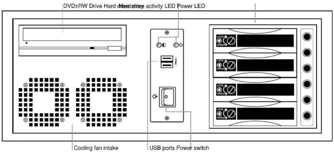
FRONT PANEL CONTROLS
The front panel of the recorder contains the devices that will be commonly used for data removal, retrieval, and backup replacement. The most common components and buttons are shown below.
XVSe

DVSe
REAR PANEL CONNECTORS
The rear panel of the recorder contains the connectors used to attach cameras, sensors, and relays to the recorder. Below are diagrams that outline the location and description of each connector.
XVSe
16 Channel (240)

16 Channel (240V)
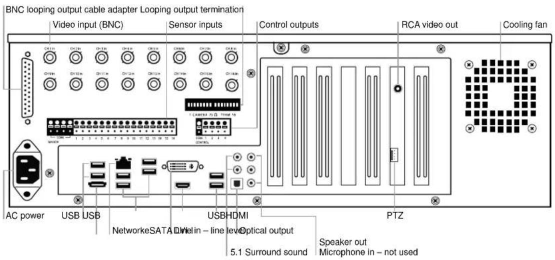
DVSe
8/16 Channel

32 Channel

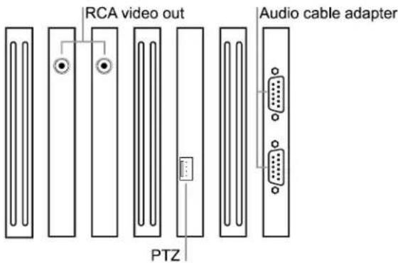
Card Configurations
240 PPS 8/16 Channel

240 PPS 32 Channel

480 PPS 16 Channel

480 PPS 32 Channel
GETTING STARTED
This chapter includes the following information:
- Included Components
- Setting up the DVR Hardware
- Optional Components
IDENTIFYING INCLUDED COMPONENTS
Surveillix recorders come with a mouse, keyboard and selected software and cables. Identify the following components to make sure everything has been properly included with the new DVR. If any of the following items are missing, contact the dealer to arrange a replacement.
 DVR Key Mouse Keyboard DVR Key Mouse Keyboard |  |  |
 Repair Disc/ Software Disc Repair Disc/ Software Disc |  Power Adapter Power Adapter |  PTZ Adapter PTZ Adapter |
 8 Channel Audio Input Cable DVI-I to VGA adapter 8 Channel Audio Input Cable DVI-I to VGA adapter |  | 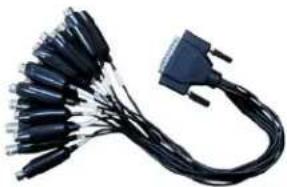 BNC Connector Cable(16 CH XVS or 32 CH DVSe only) BNC Connector Cable(16 CH XVS or 32 CH DVSe only) |
 Rack Mount Kit Rack Mount Kit |
OPTIONAL COMPONENTS
To fully utilize the recorder's potential; several optional Surveillix components are listed below. Contact the dealer for more information.
UPS UPS Power Backup
UPS Power Backups allow your DVR to remain fully functional even in the event of a power failure. UPS Power Backups also even the fluctuating power current out to provide a consistent, reliable power flow. This creates a stable environment for the DVR and reduces failure.
NP-4PKVM 4 Channel KVM Switch
The 4 Channel KVM switch allows you to have multiple boxes (up to 4) using only one keyboard, mouse and monitor. You can simply switch between the DVRs using the keyboard.
Hot Swappable Redundant Power Supplies (DVSe only)
Every DVR has the option of a dual redundant hot swappable power supply. In the event of a component failure the inoperable power supply may be removed leaving the DVR running so no break in recording occurs. Simply replace the power supply with a new one and you are finished.
Raid Controller
A raid controller is available for increased performance or data reliability.
Multiplex TV Out Monitor Output
Multiplex TV Out monitor output card is available for enhanced video output requirements
External RAID storage
An external RAID device is used for independent data reliability & provides much greater storage expandability
Gigibit NIC
Provides support for Dual Nic configurations
SCSI Interface adapter
Allows for external storage devices to be connected
KEYBOARD SETUP
To attach the keyboard to the recorder, plug the end of the Keyboard into a USB port located on the back of the machine.

MOUSE SETUP
To attach the mouse to the recorder, plug the end of the mouse into a USB port located on the back of the machine.
The mouse uses a cursor called a pointer. Pointers come in many different shapes but are most commonly shaped like an arrow.
The mouse has two buttons: a left button and a right button. Quickly pressing and releasing one of these buttons is called clicking. Sometimes you will need to double-click – or click the same button twice quickly.
In this manual:
Click means to position the mouse cursor over an item and to single click the left button.
Right click means to position the mouse cursor over an item and to single click the right button.
Double-click means to position the mouse cursor over an item and to click the left button twice.
Select means to position the mouse cursor over a radio button, checkbox, or list item and click on it.
The scroll wheel in between the two buttons is used for added navigation functionality. By moving the wheel with index finger (scrolling), quickly move through multiple pages, lines, or windows. The wheel may also function as a third button allowing the user to quickly click or double-click an icon or a selected item

MONITOR SETUP
The recorder has the following connections available to attach a monitor.

HDMI Output
DVI -I Output
DVI to SVGA Adapter
To TV / Digital Monitor
To TV / Digital Monitor
Connect adapter to DVI output to connect an analog VGA Monitor.
Attach the monitor or monitors to the rear of the recorder using the cable supplied by the monitor manufacturer. Refer to the monitor manual for detailed information on how to setup and use it.
Note The monitor must be capable of having a screen resolution of 1024 x 768 and display colors of at least 32 Bit
POWER SETUP

WARNING:
To reduce the risk of electrical shock or damage to the equipment:
Do not disable the power grounding plug.
The grounding plug is an important safety feature.
If the electrical plug you are using does not have a ground plug receptacle contact a licensed electrician to have it replaced with a grounded electrical outlet.
Plug the power cord into a grounded (earthed) electrical outlet that is easily accessible at all times.
Disconnect the power from the computer by unplugging the power cord either from the electrical outlet or the computer.
MAKING CONNECTIONS ON AN XVSe
Connecting a Video Source
There are different types of Video Sources that can be plugged into the XVSe including DVD players, VHS players, and CCTV Cameras. The back of the XVSe contains up to 16 video inputs depending on the model. The connectors use the BNC standard.

The video inputs are 75 Ω BNC connectors. Plug one end into the video source (DVD, Camera, etc.) and plug the other end into the desired BNC input on the recorder.
Connecting Sensors
Each XVSe has 16 Sensor inputs. These inputs can be used with devices such as infrared devices, motion device, glass breakage alarms, door and window trips, and many more. The Sensors can be set to Normally Open or Normally Closed inside the software.
There are 4 Common Grounds (-) and 16 sensor inputs (+). There is no power supplied to the ports so an external power supply must be used if power is necessary.

Connecting Control Outputs
Each XVSe has 4 Control Outputs. These outputs can be used to trigger devices such as Sirens, Phone Dialers, Lights, and any other relay activated device. There is no power supplied to the ports. Use an external power supply if necessary.

Use 12V, below 300mA. For controlling lights or other devices, use another external relay.
Maximum voltage is 24V AC @ 1 amp
Output uses a Form C Relay
Looping Outputs
The XVSe has 16 Looping outputs. Depending on the destination of the outputs, each output may have to be terminated. The outputs are located on the BNC Connector Cable. Attach the cable to the input for the BNC Connector Cable highlighted below.

The video inputs are 75 Ω BNC connectors. Make sure there is a video source connected to the input and then connect a cable to the Channel Out on the BNC Connector Cable. The looping outs can be connected to video monitors or combined with adapters to connect to VCR's.
Looping Output Termination
When terminating the outputs becomes necessary, the recorder has built in termination that allows you to select individual outputs to terminate individually. It is not always necessary to terminate the output when using it. It is dependent on the device with which you are connecting it to. As a rule, if the image appears distorted or virtually unviewable, it most likely needs to be terminated.
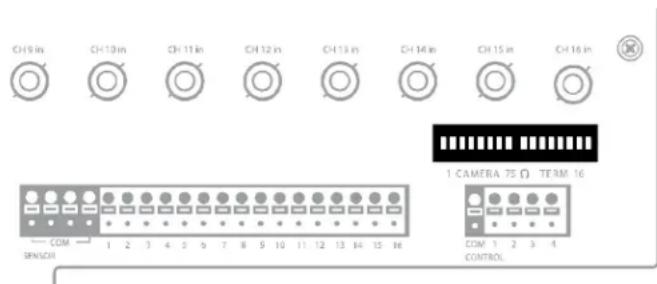
ON Not connected to a monitor (Normal) OFF Connected to a monitor (Looped)
Always leave the dipswitch set to the ON position when the Looping Outputs are not used.
Connecting a PTZ Camera
Setting up a PTZ Camera is simple. The recorder comes preassembled with an internal PTZ adapter. The cabling may be run up to 4,000 ft using 22 Gauge Twisted Pair.
It is important to understand how the PTZ connects to the recorder. The recorder outputs an RS-232 signal and converts in to an RS-485 signal which is then sent to the PTZ camera.
Attaching the 4-Pin Adapter
- Locate the PTZ adapter cable
- Connect the wires of the PTZ adapter to the PTZ camera. The yellow wire should connect to the RX+ on the camera and the orange wire should connect to the RX-.
- Connect the other end of the adapter to the XVR unit as shown.
- Assign the PTZ camera an ID number in PTZ Setup that coincides with the number assigned to the camera. This is normally done utilizing a dip-switch configuration method on the addressable dome.
Example: If the camera is plugged into input number 5, set the PTZ unit to ID number 5.
RS-422

MAKING CONNECTIONS ON DVSe
Connecting a Video Source
There are different types of Video Sources that can be plugged into the recorder including DVD players, VHS players, and CCTV Cameras. The back of the recorder contains up to 32 video inputs depending on the recorder model. The connectors use the BNC standard.
8 Channel

16 Channel

32 Channel

The video inputs are 75 Ω BNC connectors. Plug one end into the video source (DVD, Camera, etc.) and plug the other end into the desired BNC input on the recorder.
Connecting Sensors
Each recorder has up to 16 Sensor inputs. These inputs can be used with devices such as infrared devices, motion device, glass breakage alarms, door and window trips, and many more. The Sensors can be set to Normally Open or Normally Closed inside the software.
There are 4 Common Grounds (-) and 16 sensor inputs (+). There is no power supplied to the ports so an external power supply must be used if power is necessary.

Connecting Control Outputs
Each recorder has up to 16 Control Outputs. These outputs can be used to trigger devices such as Sirens, Phone Dialers, Lights, and any other relay activated device. There is no power supplied to the ports. Use an external power supply if necessary.

External Power Supply (DC 12V)
Use 12V, below 300mA. For controlling lights or other devices, use another external relay.
Maximum voltage is 24V AC @ 1 amp
Output uses a Form C Relay
Looping Outputs
The 8/16 Channel DVSe has up to 16 looping outputs. Depending on the destination of the looping outputs, each one may have to be terminated.

The 32 Channel DVSe has up to 32 looping outputs. Connect the included 16 Channel BNC Connector Cables to the 16 Channel Cable Adapter ports.

The video inputs/outputs are 75 Ω BNC connectors. Make sure there is a video source connected to the input and then connect a cable to the Channel Out on the BNC Connector Cable. The looping outs can be connected to video monitors or combined with adapters to connect to VCRs.
Looping Output Termination
When it is necessary to terminate a looping output, the recorder has built in termination that allows users to select individual outputs. It is not always necessary to terminate the output; it depends on the device to which you are connecting. As a rule, if the image appears distorted or virtually unviewable, it likely needs to be terminated.
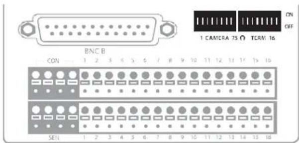
ON Not connected to a monitor (Normal) OFF Connected to a monitor (Looped)
Always leave the dipswitch set to the ON position when the Looping Outputs are not used.
Connecting a PTZ Camera
Setting up a PTZ Camera is simple. The recorder comes preassembled with an internal PTZ adapter. The cabling may be run up to 4,000 ft using 22 Gauge Twisted Pair.
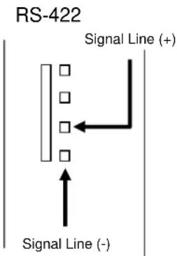
It is important to understand how the PTZ connects to the recorder. The recorder outputs an RS-232 signal and converts in to an RS-422/485 signal which is then sent to the PTZ camera.
Attaching the 4-Pin Adapter
- Locate the PTZ adapter cable
- Connect the wires of the PTZ adapter to the PTZ camera. The yellow wire should connect to the RX+ on the camera and the orange wire should connect to the RX-.
- Connect the other end of the adapter to the XVR unit as shown.
- Assign the PTZ camera an ID number in PTZ Setup that coincides with the number assigned to the camera. This is normally done utilizing a dip-switch configuration method on the addressable dome.
Example: If the camera is plugged into input number 5, set the PTZ unit to ID number 5.
HARD DRIVE ARRAY (DVSe ONLY)

Swapping a Hard Drive

- Press the Hard Drive Power Button to turn off power to the hard drive being removed.
- Turn the Button Lock to the open position and push the Handle Release Button
- Pull the Release Handle outward while removing the hard drive. Reverse steps to install.
Once the cables and adapters have been properly connected it is time to turn on the power. To turn on the power follow these steps:
- Turn on the monitor and any external peripherals (ex. Printers, External Storage Devices, etc.) connected to the recorder.
- Turn on the Secondary Power Switch located in the rear of the recorder.
- Turn on the main power switch located on the front of the recorder.
The recorder will run a series of self-tests. After two or three minutes a series of messages may be displayed as the various hardware and software subsystems are activated. Under normal circumstances you should not be asked to respond to these messages. If you are asked to respond to the messages (adding a Printer, Monitor, etc for the first time) follow the instructions carefully.
After this finishes, the Surveillix recorder software should load automatically and bring you to the main screen.
To turn off the recorder, select the Exit button on the main screen and select Power Off. The recorder will safely shutdown, it may take several minutes to shut down completely.
Caution: Always be sure to follow the proper procedures when turning off the power to the recorder. NEVER disconnect the power to the recorder while it is still running or in the process of shutting down. Doing so can cause data loss, file corruption, system instability and hardware failure

- LIMITED TWO (2) YEAR WARRANTY OF LABOR AND PARTS
- STEP-BY-STEP PROCEDURES – HOW TO OBTAIN WARRANTY SERVICE
- CRITICAL USE DISCLAIMER
- YOUR RESPONSIBILITIES
- IMPORTANT SAFEGUARDS
- IMPORTANT SAFEGUARDS, CONTINUED
- BATTERY EXPLOSION CAUTION STATEMENT
- NOTES ON HANDLING
- NOTES ON LOCATING
- NOTES ON MAINTENANCE
- NOTES ON MOISTURE CONDENSATION
- WARNING
- CAUTION
- RACK MOUNT INSTRUCTIONS
- FCC STATEMENT
- UL NOTICE
- DISCLAIMER
- USAGE LIMITATION
- TABLE OF CONTENTS
- MAKING CONNECTIONS ON DVSE 30
- HARD DRIVE ARRAY (DVSE ONLY)....34
- TECHNICIAN NOTES
- INTRODUCTION
- PRODUCT DESCRIPTION
- FEATURES
- CONTROLS AND CONNECTIONS
- FRONT PANEL CONTROLS
- REAR PANEL CONNECTORS
- XVSE
- DVSE
- 8/16 CHANNEL
- 32 CHANNEL
- CARD CONFIGURATIONS
- GETTING STARTED
- IDENTIFYING INCLUDED COMPONENTS
- OPTIONAL COMPONENTS
- UPS UPS POWER BACKUP
- NP-4PKVM 4 CHANNEL KVM SWITCH
- HOT SWAPPABLE REDUNDANT POWER SUPPLIES (DVSE ONLY)
- RAID CONTROLLER
- MULTIPLEX TV OUT MONITOR OUTPUT
- EXTERNAL RAID STORAGE
- GIGIBIT NIC
- SCSI INTERFACE ADAPTER
- KEYBOARD SETUP
- MOUSE SETUP
- MONITOR SETUP
- POWER SETUP
- MAKING CONNECTIONS ON AN XVSE
- CONNECTING A VIDEO SOURCE
- CONNECTING SENSORS
- CONNECTING CONTROL OUTPUTS
- LOOPING OUTPUTS
- LOOPING OUTPUT TERMINATION
- CONNECTING A PTZ CAMERA
- ATTACHING THE 4-PIN ADAPTER
- MAKING CONNECTIONS ON DVSE
- HARD DRIVE ARRAY (DVSE ONLY)
- SWAPPING A HARD DRIVE
Brand : TOSHIBA
Model : Surveillix DVse8
Category : Surveillance Camera