
XTR39 - Controller Xantech - Free user manual and instructions
Find the device manual for free XTR39 Xantech in PDF.


| Product Type | Controller |
| Brand | Xantech |
| Model | XTR39 |
| Dimensions (approx.) | 4.5 x 1.5 x 0.8 inches |
| Weight (approx.) | 0.2 lbs |
| Power Source | 2 x AAA batteries (not included) |
| Battery Life | Up to 6 months with typical use |
| Control Technology | Infrared (IR) |
| Control Range | Up to 30 feet |
| Number of Buttons | 39 |
| Programming Method | Code entry or auto-search |
| Device Compatibility | Most brands of TVs, DVD players, cable/satellite boxes, and audio receivers |
| Memory Backup | Retains codes for 10 minutes during battery change |
| Housing Material | ABS plastic |
| Color | Black |
| Cleaning Instructions | Wipe with a soft, dry cloth; do not use liquid cleaners |
| Battery Disposal | Recycle according to local regulations |
| Operating Temperature | 32°F to 104°F (0°C to 40°C) |
| Warranty | 1 year limited |
| Spare Parts Availability | Contact Xantech support for replacements |
| Repairability | Not user-serviceable; professional repair recommended |
Frequently Asked Questions - XTR39 Xantech
User questions about XTR39 Xantech
0 question about this device. Answer the ones you know or ask your own.
Ask a new question about this device
Download the instructions for your Controller in PDF format for free! Find your manual XTR39 - Xantech and take your electronic device back in hand. On this page are published all the documents necessary for the use of your device. XTR39 by Xantech.
USER MANUAL XTR39 Xantech
Installation Instructions
ATTENTION:
The XTR39 is shipped with the battery disconnected. You must connect the battery.
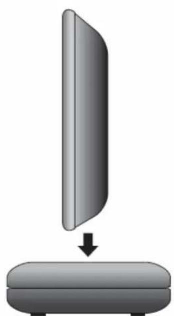
natural_image
Simple diagram showing a vertical panel being lowered into a rounded base (no text or symbols)step 1
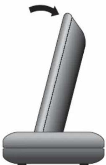
natural_image
3D illustration of a mechanical component with a curved arrow indicating rotation (no text or symbols)step 2
To ensure proper connection between the XTR39 remote and docking cradle, follow the docking procedure.
INTRODUCTION 5
XTR39 Overview 5
XTR39 Features 5
Box Contents....5
XTR39 Diagram....6
Charging Cradle Diagram....7
PRELIMINARY SETUP 7
Connecting the Battery Pack....7
Charging the XTR39 and Charging Cradle LED Indicator 8
SYSTEM SETUP....8
Touch-screen Calibration Adjustment....10
Touch-screen Calibration Test 10
PROGRAMMING SETUP 11
XTR39 Dragon™ Installation Guide 11
INSTALLING AND CONFIGURING THE XTR39 DRAGON™ SOFTWARE 16
Starting XTR39 Dragon™ Software....16
USB Connection 16
Configuring USB Port....17
Verifying PC to XTR39 Communication....19
STARTING A PROJECT....20
CREATING THE GRAPHICAL USER INTERFACE (GUI)....21
Choosing A Style 22
Building a Page (Working with GTL's)....22
Placing Source GTL's 22
Placing Function Button GTL's 23
Inserting Additional Pages for a Single Source....24
Editing GTL Properties 25
Creating Labels (GuiFX Transports and Icons) 26
Inserting Labels....28
LEARNING IR COMMANDS (CREATING PALETTE FILES) 28
Built-In IR Code Library....29
Testing IR Commands in the IR Library....30
Learning IR Commands (XIR2)....31
Using the Palette Editor 31
Editing Function Names in the Palette Editor....33
Testing IR Commands in the Palette Editor....33
Creating a Palette File 34
PLACING COMMANDS ONTO THE GTL'S (CREATING MACRO'S) 34
Selecting IR Palettes 35
Associating Commands To GTL's (Drag And Drop Commands)....35
Timed Delays....36
Delete 36
Testing Commands Placed on the virtual XTR39 Window 36
TRANSFERRING THE PROJECT....37
Firmware Update....38
Cleaning the XTR39 38
Rechargeable Battery Maintenance....38
FCC NOTICE 39
ACCESSORY ITEMS 40
WARRANTY INFORMATION 40
INTRODUCTION
XTR39 Overview
The XTR39 Color LCD touch-screen remote control from Xantech is the perfect solution to the clutter of difficult-to-use remote controls that accompany most home theater systems.
The XTR39 is a stylish, simple-to-use remote control that can be personalized via its vivid full color 3.9" touch-screen display: button layout can be customized; easily identified icons created for virtually any function or command; and multiple screen pages allow less frequently used buttons to be concealed.
Pick it up, and the XTR39 comes to life. Dedicated buttons for the most frequently used buttons such as volume, channel, power, and mute are perfectly positioned. A convenient touch-wheel control sets the XTR39 apart, allowing quick scrolling through menus and commands.
All screen buttons and icons can be programmed to perform multiple commands with a single touch. Additionally, the XTR39 can be configured to control nearly any major system in the home such as A/V system, lighting, climate control, and more.
The XTR39 can be programmed with the same functions and screen appearance as all other Xantech SPLCD SmartPad LCD ^™ in-wall touchpanels installed in the home, for consistency and simple operation.
XTR39 Features
Vivid 3.9" Color LCD touch-screen display
Fully customizable screen graphics and functions
Capable of controlling virtually every major home system
Hard buttons for frequently used commands
Four easy access programmable macro buttons
Touch-wheel control for quick scrolling through menus and commands
Eight megabyte internal memory
RF capable remote
Long-life rechargeable Lithium-Ion battery with battery status indicator and charging stand
Programmed via Xantech's XTR39 Dragon Drop-IR™ programming software
Uses same graphics and commands as SPLCD SmartPad LCD ^TM in-wall touchpanels
Box Contents
XTR39 Hand-Held LCD Remote Control
Lithium-Ion Rechargeable Battery
Charging Cradle
Charging Cradle Power Supply (+5VDC, 2Amp)
XTR39 Dragon Drop-IR Software
Instruction Manual
XTR39 Diagram
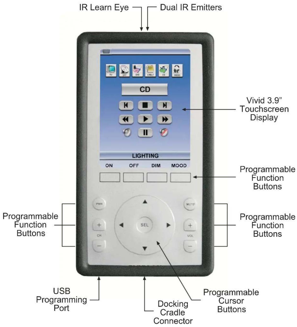
XTR39 Front View
Note: Simulated graphics.
Charging Cradle Diagram
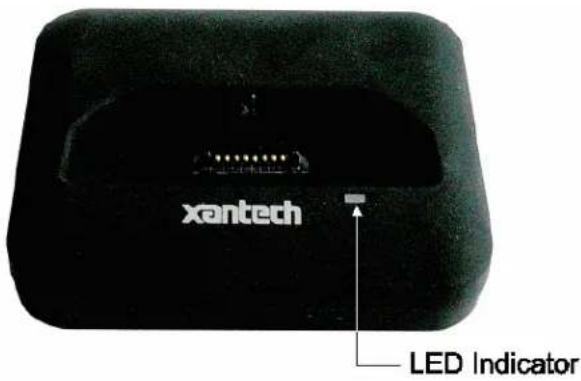
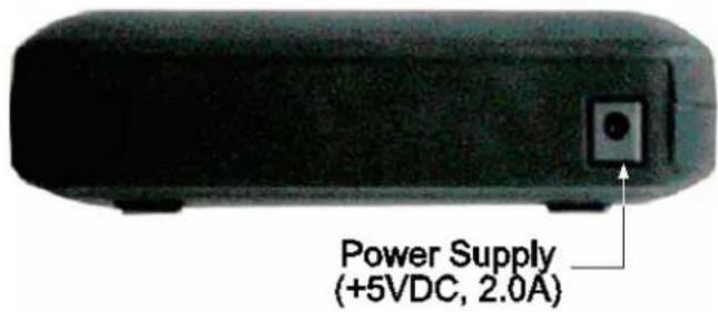
Charging Cradle Front View Charging Cradle Rear View
PRELIMINARY SETUP
Connecting the Battery Pack
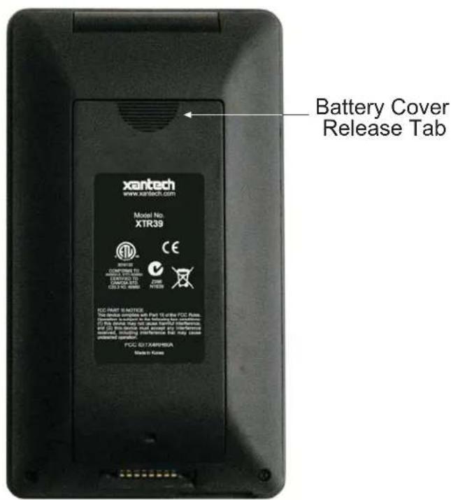
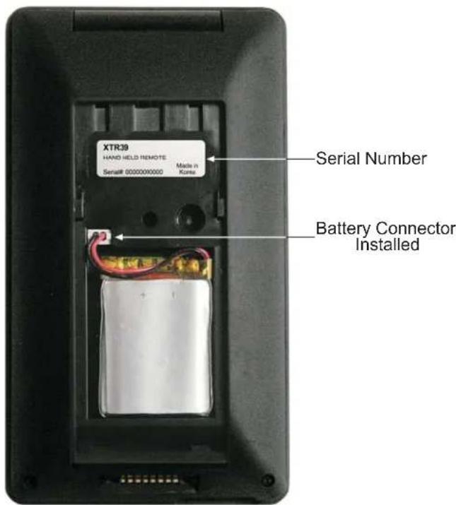
Charging the XTR39 and Charging Cradle LED Indicator
Plug the included power supply into the charging cradle. Then plug the power supply into a power receptacle. The Charging Cradle LED will blink an ‘orange’ color 3 times. This indicates the Charging Cradle is ready for use.
Making sure the battery has been installed (see 'Connecting the Battery Pack'), place the XTR39 on the charging cradle. The XTR39 must be charged at least 10 hours straight without being used. Not doing so may harm the life span of the battery.
When the XTR39 is placed on the Charging Cradle, the LED indicator will be either 'red' or 'green'.
- A 'red' LED indicates that the XTR39 battery is charging.
- A ‘green’ LED indicates that the XTR39 battery is charged and ready for use.
Battery Indicator (Touch-screen)
- The XTR39 also has a battery strength indicator. A completely filled in battery icon indicates a fully charged battery.
SYSTEM SETUP
Entering and Exiting the Setup Page
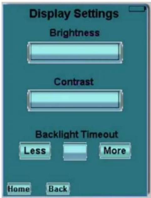
Specific settings can be adjusted on the XTR39 directly. To enter the Display Settings mode, press and hold the "MUTE" button for 5 seconds. A new "XTR39 SETUP" screen will appear.
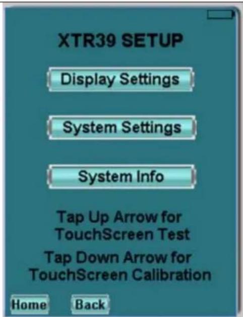
(1) Display Settings - Backlight Adjustment
Touch and drag the slider to adjust the XTR39 to a desired backlight brightness level.
(2) Display Settings - Contrast Adjustment
Touch and drag the slider to adjust the XTR39 to a desired contrast level.
(3) Display Settings - Backlight Timeout
Press “LESS” or “MORE” button to select the desired backlight timeout. This determines the amount of time, in seconds, when the backlight will turn off after the XTR39 is no longer is use. Timeout can be set between 5 seconds and 30 seconds.
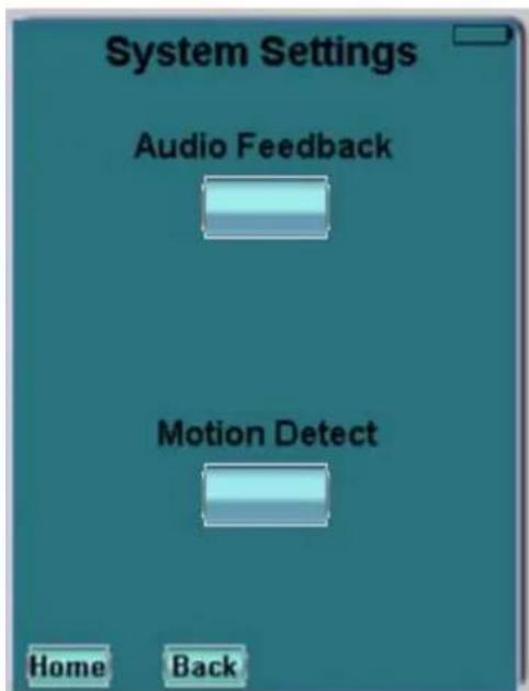
(1) System Settings - Audio Feedback
The XTR39 can emit a distinctive 'beep' that indicates when any button or GTL (Graphical Touch-Link) is pressed. This allows the XTR39 to provide feedback that a button has been pressed. The 'beep' sounds can be enabled or disabled by pressing the button. Every press toggles between 'on' and 'off'.
(2) System Settings - Motion Detect
The XTR39 can detect motion when it is being handled by a user. This allows the XTR39 to turn on the backlight to the touch-screen without having to use the touch-screen or any buttons. The motion detect can be enabled or disabled by pressing the button. Every press toggles between 'on' and 'off'.
| (1) System InformationThe XTR39 can display the firmware version and project information.The top displays the system firmware version.The bottom displays the IR library version. | 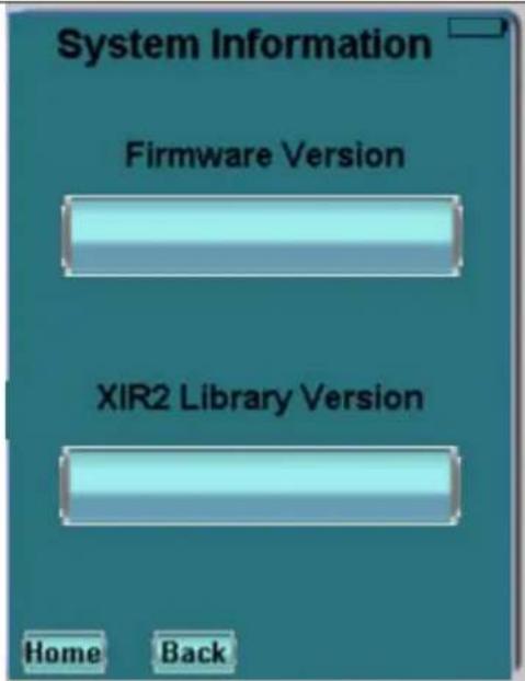 | |
Touch-screen Calibration Adjustment
The accuracy of triggering a Hot-Spot associated to a GTL (Graphical Touch-Link) can be calibrated. It is advised to use a PDA stylus for increased precision.
- From the "XTR39 Setup" page, press the down-arrow to enter calibration adjustment mode.
- A black dot on an all-white background will appear. Using a PDA stylus or your smallest finger, press the black dot and release.
- Another black-dot will appear. Press the black dot and release.
- Again, another black-dot will appear. Press the black dot and release.
- A total of three calibration points appear. Now press anywhere on the touch-screen and a black dot will appear in that exact location.
- Wait for the unit to exit calibration mode by doing nothing for 10 seconds.
Touch-screen Calibration Test
The accuracy of the triggering a Hot-Spot associated to a GTL (Graphical Touch-Link) can be tested. It is advised to use a PDA stylus for increased precision.
- From the "XTR39 Setup" page, press the up-arrow to enter calibration adjustment mode.
- To enter the "XTR39 Setup" page, press and hold the "MUTE" button for 5 seconds.
- Press anywhere on the touch-screen and a black dot will appear in that exact location.
PROGRAMMING SETUP
XTR39 Dragon™ Installation Guide
This guide provides users with step by step instructions on how to install the XTR39 Dragon™ software.
Requirements:
• 1.0 GHz or greater processor (CPU)
• Windows 2000 and Windows XP
- 650 MB Hard Drive space (you will need more as your libraries and projects expand)
• 256 MB RAM (512MB preferred)
- Mouse, Keyboard, USB port
Installation
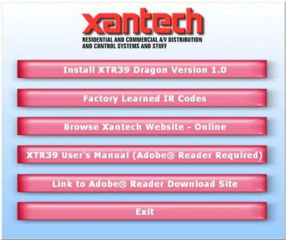
- Place the Installation CD-ROM into the computer CD or DVD drive. The CD-ROM will auto-run and the menu, as seen below, will appear. Press the "Install XTR39 Dragon Version 1.0" button.
- The installation process will begin:
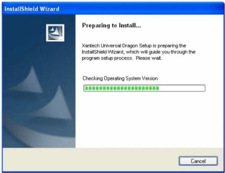
Note: If you do not have the Microsoft .NET (dotnetfx.exe) or InstallShield update on your computer, this will get installed first.
- Click on the Next button:
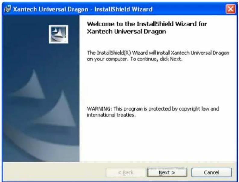
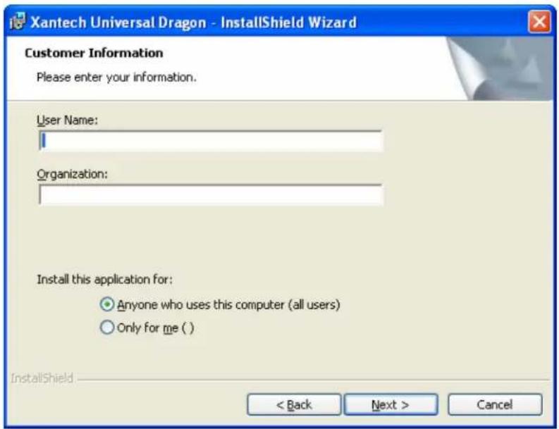
- Enter your name and company and select if the installation should only be available to you or to anyone else who may log into your computer, then click Next:
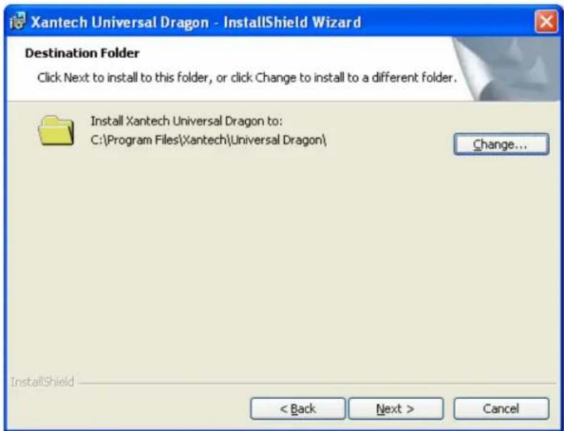
- The default installation path for XTR39 Dragon™ is 'C:\Program Files\Xantech\XTR39Dragon', if this is acceptable click Next. Otherwise click on the Change button and enter the location you wish to install XTR39 Dragon™:
- The installation will proceed showing the user the current Status:
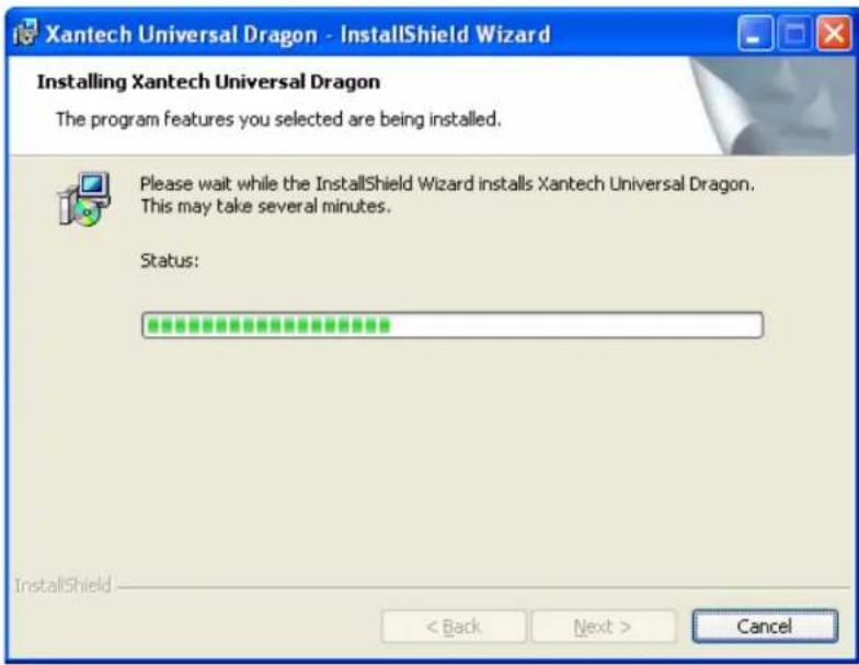
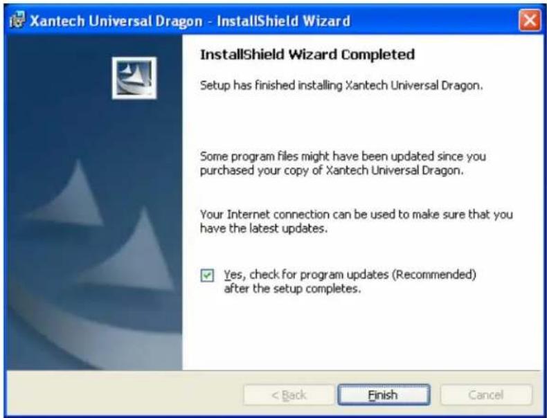
- After installation is complete. Click on the Finish button. (Make sure to leave the 'Yes, check for program update (Recommended) after the setup completes' in order to ensure that you have the latest version of XTR39 Dragon™ installed:
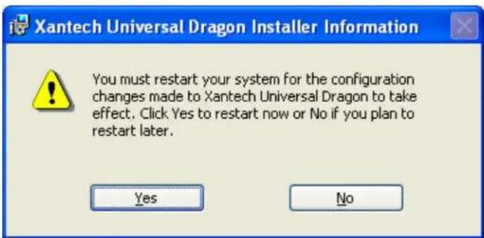
- The installation package will ask you to reboot your computer. Click Yes so that the installation process can be completed. If any other applications are open, be sure to save your work.
- After your computer reboots, the installation package will check to make sure that you have the latest version of XTR39 Dragon™ on your computer.
- You can now run the XTR39 Dragon™ software by double clicking the shortcut on your desktop:

Or select XTR39 Dragon™ from your start menu under the Xantech start folder (Start -> Programs -> Xantech).
CONFIGURING THE XTR39 Dragon™ SOFTWARE
Starting XTR39 Dragon™ Software
After the successful installation of the software, double-click the XTR39 Dragon™ icon on your desktop or:
- From START menu, choose Programs.
- Select Xantech and click on the XTR39 Dragon™ Icon from the menu.
- The program loads and opens to the following XTR39 Dragon™ opening screen.
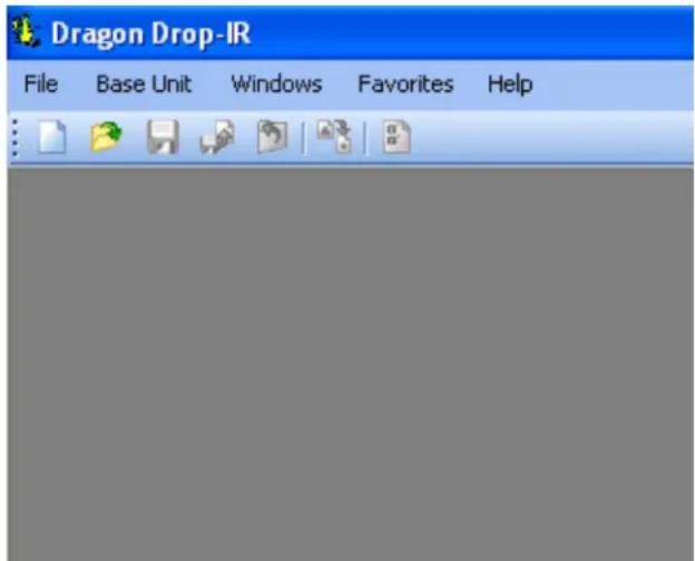
XTR39 Dragon™ Opening Screen
USB Connection
Open the access cover on the XTR39 and pivot the cover down. Connect the wide end of the included USB cable to the USB port of your PC and the small end to the connector on the lower end of the XTR39 unit (next to the docking cradle connector).
NOTE: The USB connection requires a 'B' Type connector to interface with the XTR39. USB cable is included with the XTR39.
When the XTR39 is connected to the Computer USB, the backlight will remain on. There is no backlight timeout.
Configuring USB Port
To configure the USB Port for the first time, complete the following instructions:
- Connect the XTR39 to the computer via the USB port. Under Windows XP, a Found New Hardware Wizard window asking to connect to Windows Update will appear. Select "No, not this time" and click "Next".
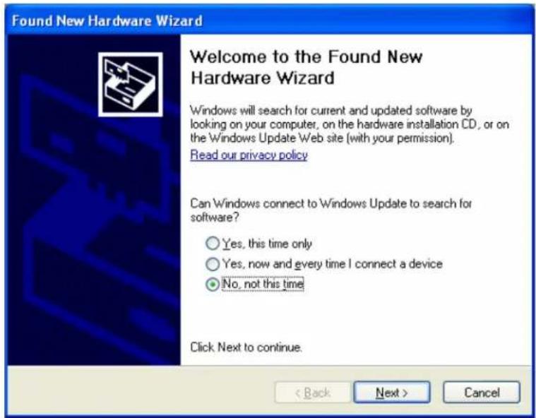
- The wizard will ask what to do next. Select "Install the software automatically" and click "Next". Be sure the XTR39 Dragon CD-ROM is in the computer. This is where the USB drivers reside.
![Found New Hardware Wizard This wizard helps you install software for: USB Device If your hardware came with an installation CD or floppy disk, insert it now. What do you want the wizard to do? • Install the software automatically [Recommended] • Install from a list or specific location [Advanced] Click Next to continue. < Back Next > Cancel](/content/2026/05/1001746/images/78b698ecfdf383fbb5e8e07bb2e011c041bc65f4c68f6dfaea33cdc49eee244d.jpg)
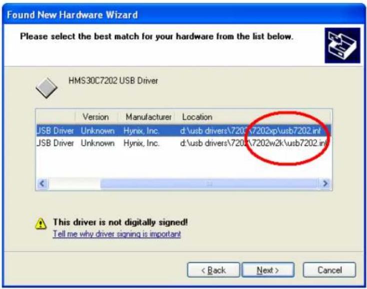
- A list of USB drivers will be displayed. Select the driver that applies with the computer's operating system. For Windows XP, select the driver found in the "7202XP" folder. For Windows 2000, select the driver found in the "7202w2k" folder. Click "Next".
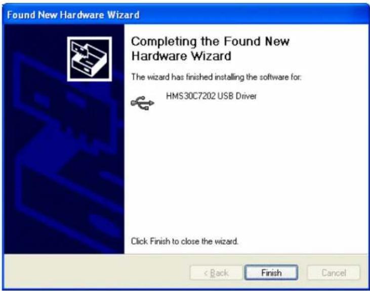
- The XTR39 is now connected to the computer and can be programmed with XTR39 Dragon. Click "Finish" to exit the Found New Hardware Wizard.
Programming the XTR39 system is a two-step process:
Creating the GUI (Graphical User Interface) Screens.
Assigning functions (macros) to the GTL's (Graphical Touch Links) to control external devices.
Through XTR39 Dragon™ Software, both of these tasks are easily performed. The software contains built-in Style libraries for creating the GUI screens as well as IR-Code libraries for programming each of the GTL's. This makes programming the XTR39 a very quick and easy process.
Verifying PC to XTR39 Communication
("Who Am I" Base Unit Version Verification)
Before continuing, it is recommended to verify proper communication between the PC and the XTR39. This can be done by performing a “Who Am I…” function.
- Connect the XTR39 to the computer via a USB cable (included).
- Open the XTR39 Dragon application as previously described.
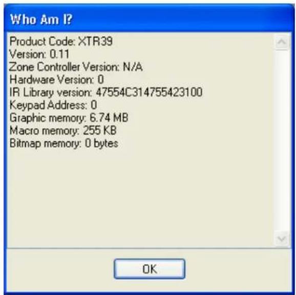
- Click on the Base Unit Menu and select Who Am I... and then XTR39
- A window will appear displaying the XTR firmware version.
- Click OK to complete the verification.
Note: If a message is returned stating: "Unable to Determine Base Unit" this could be due to the following:
- The XTR39 is not powered ON. Please check the power state of the unit.
- There is a communication error between the PC and the XTR39. Please verify the USB cable is properly connected to the unit. When the USB cable is plugged into the PC and the XTR39, the backlight on the XTR39 will stay on (no backlight timeout).
STARTING A PROJECT
With the XTR39 Dragon™ software open and the COM PORT communication verified proceed as follows:
From the File menu choose "NEW PROJECT" (CTRL+N) or choose "OPEN PROJECT" (CTRL+O) to modify an existing project file. You may also use the NEW PROJECT or OPEN PROJECT icons located on the Tool Bar at the top of the page.
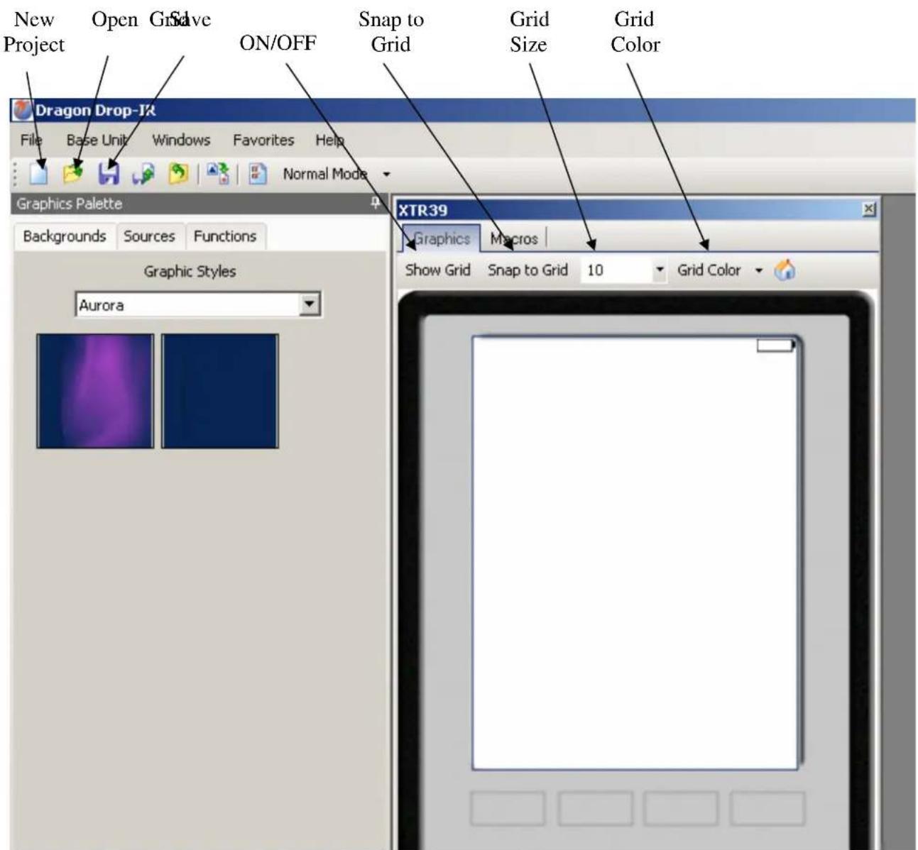
SPLCD Graphic Page Edit Screen
CREATING THE GRAPHICAL USER INTERFACE (GUI)
Through XTR39 Dragon™ software, you can easily create stylish and intuitive screens in multiple pages for controlling any IR Device. Once a project is created and a setup environment chosen, you are automatically placed in Graphics mode and are now ready to create your GUI (Graphical User Interface) screen.
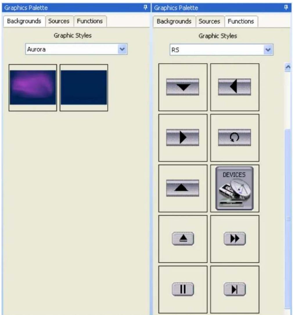
Graphics Screen (Choosing Styles)
Choosing A Style
Multiple STYLES of Backgrounds, Source Buttons, and Function Buttons are included in a graphics library within the software. Each STYLE contains its own set of Backgrounds and GTL's (Graphical Touch Links). Once a STYLE is selected, only it's associated Backgrounds, Source buttons and Function Buttons (GTL's) will be available (i.e. Styles can not be mixed).
Backgrounds
To choose a style:
- Make sure you are in Graphics Mode. If not, click on the Graphics TAB in the XTR39 window. The GRAPHICS window should now be displayed in the work environment.
- Click on a STYLE from the list in the graphics palette window and browse the associated Source and Function GTL's shown in the list until a desired style is found.
- Once a suitable style is found, click on the Backgrounds TAB and then click-&-drag (drag-&-drop!) the background onto the XTR39 Systems window.
Note: Some backgrounds will have the "HOME", "PREV", "NEXT", and "FAV" tabs already placed on the background. Using these backgrounds will speed up the project creation process.
Building a Page (Working with GTL's)
GTL's (Graphical Touch Links) are in plain terms, a graphical button that can be pressed to initiate a macro of IR, delays, repeat, internal commands or to call up a page of additional GTL's. Source GTL's will always call up a page of Function GTL's and can also have a Macro associated with it if so desired. Function GTL's can initiate Macros, call up an additional page of Functions, or do both with the same touch of the GTL. (i.e. Creating a MENU GTL can initiate a macro to call up a menu screen on a DVD player AND call up an additional page on the XTR39 screen containing the Cursor GTL buttons to be used when using the DVD menu.
Placing Source GTL's
Once the Background is placed in the Systems window, click on the Sources TAB in the GRAPHICS palette window to display the Source buttons associated with that Style.
- Select a desired Source button (i.e. DVD, SAT, VCR etc..) and in the same manner, drag-and-drop the Source GTL onto the grid. Note: If a Source button with the proper legend (DVD, SAT, etc..) is not shown in the list, select the BLANK Source button (no lettering on the GTL) and drag it onto the Background. BLANK GTL's may be edited and customized for text and color. Please see the section Editing GTL Properties below for instructions.
- Once on the Grid, the GTL can be placed anywhere on the screen. To move the GTL either Click and Drag to the proper placement, or simply select the GTL with the mouse and then use the arrow keys on the PC Keyboard to move the GTL around.
- Repeat Steps 1 & 2 for all desired Source buttons
Note: When a Source GTL is placed on the screen, you must right-click on the Source GTL and select "navigate". This will take you to a new PAGE for placing Function GTL's associated with that Source. You can also double click on the SOURCE button.
Placing Function Button GTL's
Once a Source page has been inserted, you may now start placing Function Buttons (GTL's) associated with that Source onto the Source Page.
- Click on the Source button located in the XTR39 window. The Source button should now appear selected. Note: GTL's have an UP and DOWN graphic associated with them. UP depicts the GTL in its non-selected state and the DOWN graphic depicts the GTL in its Selected state. The UP and DOWN graphics can be edited. Please see Editing GTL Properties for more information on this.
- Right click on the Source button and select navigate. This will take you to a new page where the Function button for a specific Source selected will be placed.
- Click on the Functions TAB in the GRAPHICS palette window. All of the Function Buttons associated with that Style will be displayed.
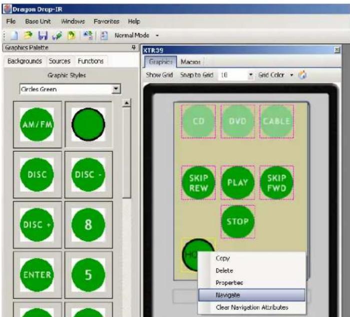
- Select a Button and drag-and-drop it anywhere on the Background in the XTR39 Systems window.
- If a desired Function Button is not shown in the list, simply select a BLANK button and drag it onto the Background. As mentioned above, this button can be edited to display the desired text and color you wish.
- Repeat steps 2 & 3 for all desired Function Buttons for that Source.
Note: You may also place a Text Label onto the Background to describe the function of a button or group of buttons. This may be desired for Volume or Channel Up/Down controls. See “Editing GTL Properties”.
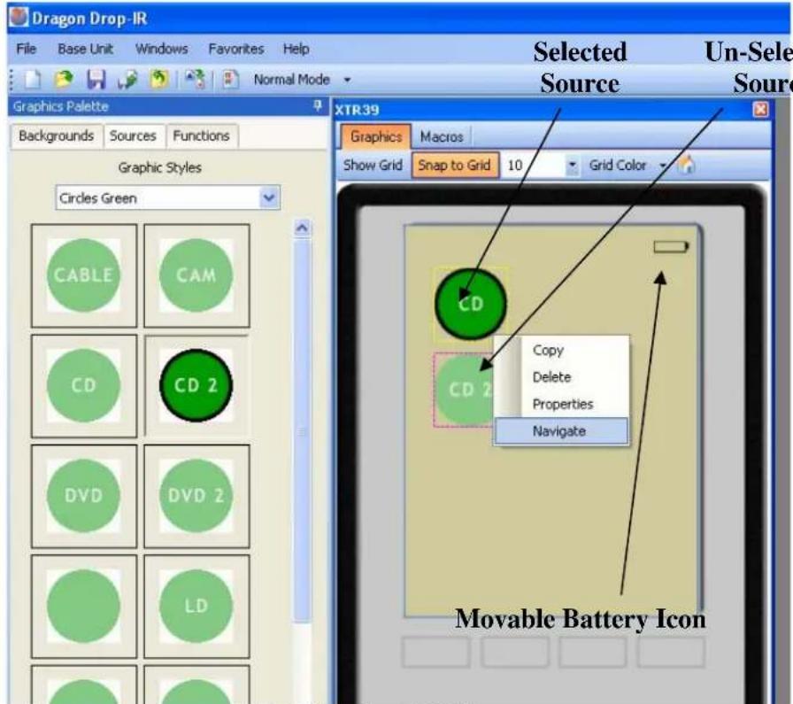
Building the GUI Screen
Inserting Additional Pages for a Single Source
Additional blank pages can be inserted for a given source. After a blank page is inserted, it may be populated with Function Buttons just as described in the previous section. This may be useful either when a page becomes full of commands or for easier operation (i.e. separating the Motion Control buttons and Menu Navigation Buttons of a DVD Player on separate pages).
The Blank Page is always inserted AFTER the current page you are inserting from.
To insert a page into an existing Page, complete the following:
- Select the Source button of the desired page (if already on the page to be inserted from, go to Step 2).
- Drag a Function Button onto the existing page to be used as a GO TO PAGE button.
- Using the PC mouse or other pointing device, right-click on the GTL button you wish to use to navigate to the next page and select Insert New Page from the drop-down menu.
- A new page is now inserted and may be filled with additional GTL buttons.
- You may now insert additional pages in the same manner if so desired or place a GTL button to return to the previous page.
To Return to the Previous Page, complete the following:
- Drag a Function Button onto the existing page to be used as a GO TO PAGE button.
- Using the PC mouse or other pointing device, right-click on the GTL button you wish to use to navigate to the previous page and select Insert 'Go To Previous Page' from the drop-down menu.
Note: This button can also have a macro associated with to perform a function on the actual Source Component as well as taking the user to the Next Page. For example, a MENU button can be used to call up a menu on the DVD itself and also bring up a page of MENU Cursor buttons on the XTR39 panel for the User to use to navigate through the DVD Menu.
Editing GTL Properties
Properties of a GTL button can be edited for Text, Font and color. This allows the user to drag a blank GTL button on to the GUI page and edited it to their liking. Each GTL has two states a Down and an Up state. Each of these states can be edited separately to give a unique appearance when either selected or non-selected.
To edit a GTL proceed as follows:
- Right-click on the GTL to be edited.
Note: Existing TEXT on a GTL cannot be changed or edited. It is preferred to use a BLANK GTL for customization.
- Select Properties from the pop-up menu.
- Click on the Edit Text / Graphics Tab
- To Change or Add text to the button, click inside the Caption dialog box and type the desired text.
Note: As previously mentioned above, each GTL button has both an Up and Down image associated with it. The Up image is how the GTL text appears when not-selected and the Down image is how the GTL text appears when it is-selected. Both the Font and Color can be edited for each of these states. Select the Font button on either the UP IMAGE or DOWN IMAGE to change the existing Font. The font size and font style can all be edited here to any True-Type font currently installed on your PC.
- After the Font type, Size, and Style are selected, click OK to save the settings.
- To change the Color of the text, click on the COLOR button and select the desired color from the color palette and click OK.
If both the UP and DOWN images are to be the same, click the Use caption in all images check box.
- To view the changes before exiting the EDIT window, simply click on APPLY. If no more changes are to be made, click on OK to store the changes.
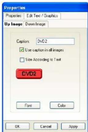
Edit Text / Graphic TAB
Creating Labels (GuiFX Transports and Icons)
GuiFX fonts (www.guifx.com) are automatically installed with XTR39 Dragon. There are two types of fonts, transports and icons. To use a GuiFX symbol, select GuiFX Transports or GuiFX Icons as a font. Enter the respective key (shown on the table below) in the caption text box of the Edit Text / Graphics window. For non single-stroke key's, press and hold "ALT-X" and then type the four digit code. Release "ALT-X" and the symbol will appear.
GuiFX Icon Symbols
| KEY | DESCRIPTION | |
| ` | Gui | |
| a | Music | |
| b | Screen Control | |
| c FM / XM | ||
| d VCR / DVR / DAT | ||
| e | Lighting | |
| f TV / 16x9 | ||
| g TV / 4x3 | ||
| h | Satellite | |
| i | MP3 | |
| j | Curtain / Shades | |
| k Navigate / Map | ||
| l | Projector | |
| m | TIVO | |
| n Internet / www | ||
| o | Optical Disc | |
| p | Temperature | |
| q | Headphones | |
| r | Select | |
| s Floor plan / room | ||
| t | Time | |
| u Security / Monitor | ||
| v | DVD | |
| w | ||
| x Compact Disc Audio | ||
| y | Temperature 2 | |
| z | Game | |
| KEY | DESCRIPTION |
| 0 Signal Strength 0% | |
| 1 Signal Strength 0% | |
| 2 Signal Strength 0% | |
| 3 Signal Strength 0% | |
| 4 Signal Strength 0% | |
| 5 Signal Strength 0% | |
| 6 Battery Strength 0% | |
| 7 Battery Strength 0% | |
| 8 Battery Strength 0% | |
| 9 Battery Strength 0% | |
| “ Swimming pool | |
| # Water closet | |
| % Surveillance Camera | |
| $ Setup / Tools | |
| / Shower | |
| & Intercom | |
| ‘ Hot Tub | |
| ( Computer | |
| ) Gate | |
| * Water Feature | |
| + Fireplace | |
| , Garage Door | |
| ! Popcorn Machine | |
| . Telephone |
GuiFX Transport Symbols
| KEY | DESCRIPTION | |
| ▶ | 1 | Play |
| ■ | 2 | Stop |
| || | 3 | Pause |
| ▶▶ | 4 | Fast Forward |
| ◀◀ | 5 | Rewind |
| ▶▶| | 6 | Index Forward |
| |◀◀ | 7 | Index Backward |
| ● | 8 | Record |
| ▶| | 9 | Skip Forward |
| |◀ | 0 | Skip Backward |
| ▼ | ‘ | Instant Replay |
| ◀◀ | - | Sound On / Volume |
| ◀ | = | Sound Off / Mute |
| ▶ | ] Next / Right | |
| ◀ | [ Prev / Left | |
| ! | Thumbs Up | |
| @ | Thumbs Down | |
| ◀◀ | $ | Frames Backward |
| ▶▶ | % | Frame Forward |
| |□| | ^ | On Screen Display |
| ◀◀ | & | Reverse / Open |
| ◀◀ | * | Reverse Slow Play |
| ▶◀◀ | ( | Freeze Frame / Close |
| ◀◀ | ) | Reverse Play |
| ▶ | + | Slow Play |
| ◀◀ | – | Sound Off / Mute |
| { | Focus Short | |
| } | Tracking | |
| ▲ | | | Focus Long |
| \ | Tracking | |
| “ | Illuminate Display | |
| ‘ | Down | |
| ▲ | : Eject / Channel Up | |
| ▲ | ; | Up |
| ↑ | , | Cursor UP |
| ↓ | . | Cursor DOWN |
| ← | < | Cursor LEFT |
| → | > | Cursor RIGHT |
| ? | Camera Mode | |
| KEY | DESCRIPTION | |
| / Enter / Return | ||
| Q Locked / Secure | ||
| W Unlocked / Insecure | ||
| E | PIP Select | |
| R | Microphone | |
| T | Time Shift | |
| Y | Programmable Timer | |
| U | Live TV | |
| I Mail / E-mail | ||
| O | Disk Activity | |
| P | Send-Receive | |
| A | Cancel Picture | |
| S | Keylock | |
| D | PIP Shift | |
| F | PIP Swap | |
| G | PIP Freeze | |
| H Home / Start | ||
| J | Delete / Erase | |
| K | Zoom + | |
| L | Zoom - | |
| Z | Headphones | |
| X | Power / Stand-by | |
| C | Menu | |
| V | Program Guide | |
| B | Picture-in-Picture | |
| N | Zoom 1:1 | |
| M | Zoom Default / Search | |
| # | Subtitles On / Off | |
| ~ | Video Input | |
| 0198 | Text Mode | |
| 0199 | Time On-Screen | |
| 0200 | Page / Screen Up | |
| 0201 | Page / Screen Down | |
| 0202 | TV and Text Mixed | |
| 0203 | Page Enlargement | |
| 0204 | Split Screen Swap | |
| 0205 | Split Screen Freeze | |
| 0206 | Split Screen | |
| 0207 | Video Output | |
| KEY DESCRIPTION | ||
| 0208 | Movie Expand | |
| 0209 Data Send / Receive | ||
| 0210 | Picture Freeze | |
| 0211 | Personal Preferenc | |
| 0212 Firewire / IEEE1394 | ||
| 0213 | USB | |
| 0214 Main Index Page | ||
| 0215 | On-Screen Help | |
| 0216 | Contrast | |
| 0217 | Saturation | |
| 0218 Brightness / Contrast | ||
| 0219 | Brightness | |
| 0220 | Portrait | |
| 0221 | Landscape | |
| -/-- | 0222 Single / Multi-Digit | |
| HI | 0223 | 1^st or 2^nd Language |
| PP | 0224 | Previous Program |
| CC | 0225 | Closed Caption |
| 0226 | Lights On | |
| 0227 | Lights Off | |
| 0228 | Door Closed | |
| 0229 | Door Open | |
| 0230 | Window Closed | |
| 0231 | Window Open | |
| 0232 | Keyboard | |
| 0233 | Keypad | |
| 0234 Color Test Pattern | ||
| 0235 | Page Up | |
| 0236 | Page Down | |
| 0237 | Stop | |
| 0238 | Channel Down | |
| →I | 0239 Adv. / 30-sec skip | |
| ♥ | 0240 | Favorites 01 |
| ★ | 0241 | Favorites 02 |
Inserting Labels
A Label may be inserted anywhere on the GUI screen to give more detailed description to a GTL or a group of GTL's. The label may even be used as a Function GTL or even as a Source GTL if so desired.
To insert a Label proceed as follows:
- Right-Click on any blank area (no GTL's) in the XTR39 window.
- From the Drop-Down menu, select whether this will be a text Label, text-only Source Button, or a text-only Function Button.
- Once the label is placed in the Systems window, move the label to its desired location.
- Right-Click on the label and select Properties from the drop-down menu to edit the text as outlined in the previous section.
LEARNING IR COMMANDS (Creating Palette Files)
IR Codes from Manufacture's remotes of each of the components you wish to control from the XTR39, may be learned into the XTR39 Dragon™ software and stored in Palette files for placement onto the XTR39. In order to do this, the XTR39 must be connected to the PC as outlined above.
NOTE: Before starting this section, included in the XTR39 Dragon™ software, is an extensive IR Code Library. Before learning IR commands from multiple remotes, check the IR Library to see if your IR commands for each of the components you wish to control are listed.
NOTE: If you have previously created Palette files in any other versions of XTR39 Dragon™ software on your PC (for programming URC-2's, MRC88, etc) these files can be Imported by clicking on the
Import button on the Palette Editor Import and then browsing to the location of the palette you wish to import.
If all of your codes are either located in the IR Code Library or are already learned in palettes, please proceed to the section entitled "Placing Commands onto the GTL's".
Built-In IR Code Library
The XTR39 Dragon™ software has a built-in IR Code Library. This is basically a large database of manufacture's IR commands for a whole assortment of components at your disposal. If your manufacture's codes are in our database there might not be any need to 'teach' IR commands into the system. To check the XTR39 Dragon™ software's extensive IR Code Library, do the following:
- Click on the Palette Editor on the right side of the application if it is closed.
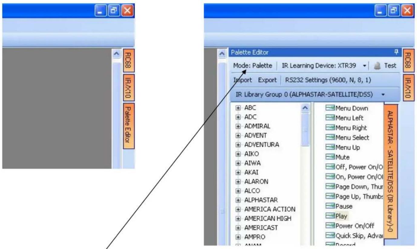
- Click on the mode button to change the "Mode: Palette" to "Mode: Edit"

- Click on the Manufacturer and then the Component Type (i.e. VCR, DVD etc.)
A list of Command Groups for that manufacturer's components IR codes will be displayed. You will need to test commands from these different Command Groups to see which one works with your component. Please see the next section entitled "Testing IR Commands in the IR Library".
Note: Some manufacturers have multiple sets of IR commands. It is a good idea to verify this to make sure the correct IR command is used. Simply click the down arrow next to "IR Library Group" and try IR commands under each 'Group'.
Testing IR Commands in the IR Library
Once you have located all of the Command Group codes for the appropriate
Manufacturer/Component, you will need to test the commands to see which Command Group is associated with your specific component.
NOTE: To test commands out of the Library, the PC running XTR39 Dragon™ software must be connected to the XTR39 via the USB programming port.
With the Manufacturer and Component expanded and the proper library selected.
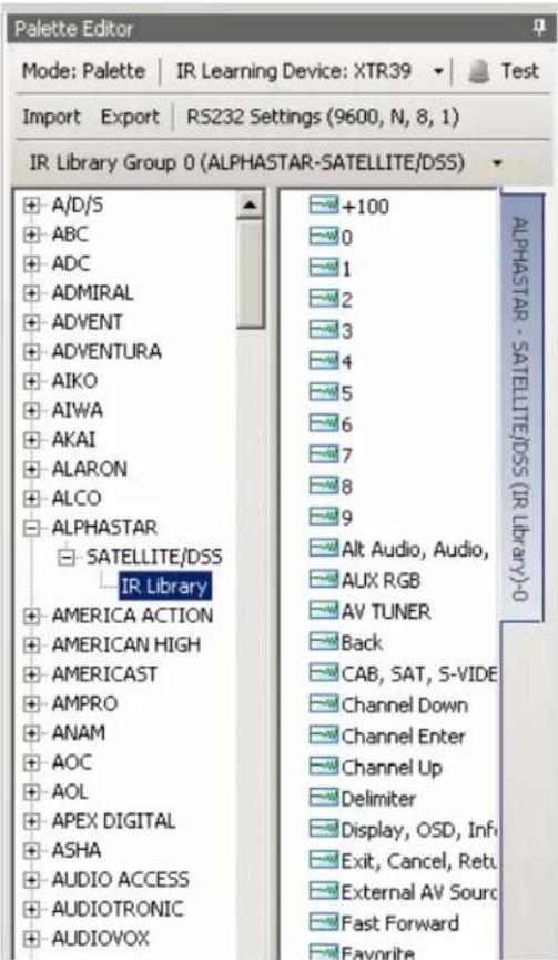
- In the palette editor window, with the PC still connected to the XTR39 programming port, select
the "TEST" button
The TEST button should now become highlighted
-
Click on the command listed in the IR Library. The controlled component should respond to each command sent. (i.e. "Power" turns the source ON or OFF, "PLAY" plays the content etc.) If a component does not respond to a command, click on another Command Group listed under that manufacturer and retest.
-
If the codes for the specified component are present, you are now ready to start creating Macro's under the GTL buttons you created in the previous section. Please see the Section entitled "Placing Commands onto the GTL's". If no working commands can be found in the IR Library, please proceed to the following section entitled "Learning IR Commands (XIR2)".
Learning IR Commands (XIR2)
An IR Learning Eye is located on the top end of the XTR39.
Note: Commands learned through the XTR39 front learning eye (XIR2 method) are NOT backwards compatible to other Xantech devices (i.e. MRC44/88, URC-2 etc...).
Palettes created in earlier version of Dragon Drop-IR ^™ software (XIR1 method) CAN be imported into the XTR39 Dragon ^™ software.
Note: When learning IR commands through the front learning-eye, it is suggested that the environment be free of any IR interference. This could include Fluorescent or Halogen lighting, sunlight, Plasma or LCD displays and interference from PC Monitor display.
Using the Palette Editor
Note: The Palette Editor is available whether a project is opened or not.
- Click on the Palette Editor tab on the right side of the application if it is closed.
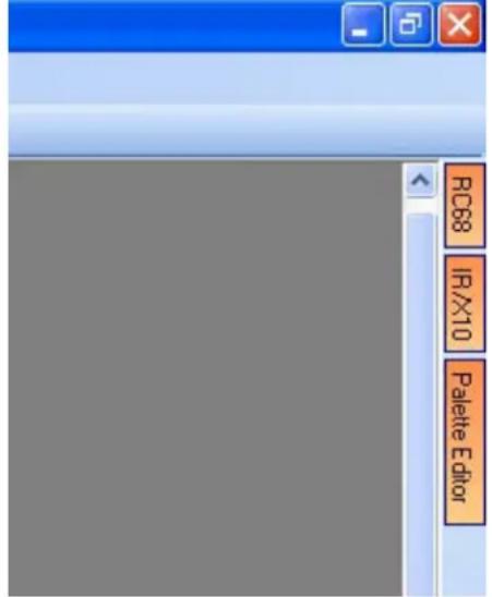
- Locate and Select the ⚠ symbol next to the desired BRAND (i.e. Sony, Panasonic etc). A list of Components will appear. (See later section for ‘Adding Brands’.)
- Locate and Select the symbol next to the type of COMPONENT (DVD, SAT etc) (See later section for 'Adding Components and Functions').
-
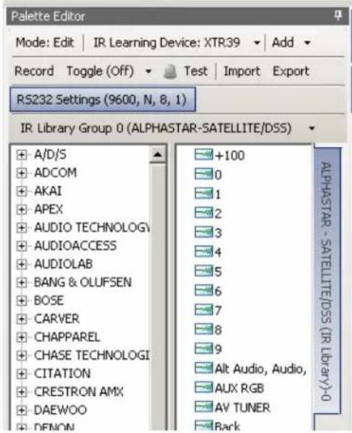
The Palette Editor will now be open to the "Brand" & "Component" selected. A list of FUNCTIONS for that type of component will appear. Review the list of Functions and compare to the source remote. If your function is not displayed or not named appropriately see the section entitled "Editing Function Names in the Palette Editor".
-
Click on the RECORD button in the middle of the Palette Editor.
Record
The RECORD button text will become highlighted. Record (Note: You must be in EDIT mode) Dragon is now ready to learn the IR codes for the specific brand/component selected. Note: Before performing step 6, read steps 6 thru 8 as the RECORD process is a timed function. You will have 10 seconds to perform the process before the system times out.
-
Place the Teaching remote pointed towards the IR Learn eye on the XTR39. The Teaching remote should be approximately 2 inches from the IR Learn eye on the XTR39.
-
Select the command the left side of the Palette Editor (i.e. Power, Play, Stop etc.). A message stating "Waiting to receive IR" will appear
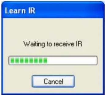
- While continuing to keep the source remote within 2" from the IR learning eye, press and release the corresponding command button on the source remote. A symbol (1) will appear to the left of the selected function indicating that an IR code has been learned.
Note: If you wait longer than ten seconds or the IR code was learned improperly, a time-out message will appear.
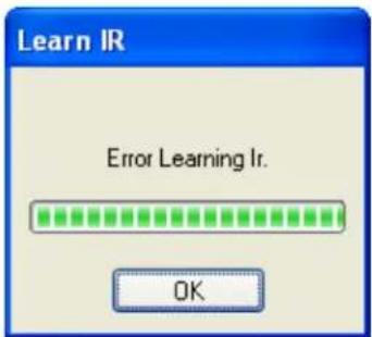
Click "OK" and try again. If you continue to have problems learning commands, please see the Trouble Shooting section at the end of this manual.
Note: When teaching commands in this fashion, only a quick tap of the teaching remote is required. Do not press and hold the button until the message goes away.
- Repeat steps 6 thru 8 for all of the source buttons to be used on the XTR39.
Note: Make sure that the IR Learning device is set to "XTR39".
Editing Function Names in the Palette Editor
If a function displayed on the Source Components Remote is not displayed in the function list on the left hand side of the Palette Editor window, you can either RENAME an existing function or ADD a new function to the list. Editing function names in the Palette Editor will only effect the Palette File you are currently saving to (i.e. Making a change to a function under DENON DVD will only appear in DENON DVD).
To Rename an Existing Function:
- Right-click on the function to be renamed.
Choose from the drop-down menu.
Edit the text as desired and press ENTER on your keyboard to save.
To Add a New Function:
Right-click on a blank area of the list and select from the drop-down menu.
Enter the name of the new function as you would like it to appear in the list and press ENTER on your keyboard to save.
Testing IR Commands in the Palette Editor
- Be sure corresponding source for the commands to be tested is ON and connected to the XTR39.
- Direct the XTR39 towards the source (IR eye).
- With the PC still connected to the XTR39's programming port, select test in the Palette Editor window.
The TEST button text will highlight Test
- Click on each of the command names one-by-one that need to be tested. The red light to the left of "TEST" will turn on as the IR command executes.
- The controlled component should respond to each command sent.(i.e. "Power" turns the source ON or OFF, "PLAY" plays the content etc.)
NOTE: Only functions with the
symbol will execute.
- If a component does not respond to a command, re-learn and re-test the IR command until the component responds.
- Repeat steps 1 thru 6 for all commands to be tested.
Creating a Palette File
A Palette File is a file of learned commands that are ready to be placed under a GTL for use in the XTR39.
Note: As previously mentioned, Palette files created in XTR39 Dragon ^™ software (XIR2 method) cannot be used with other devices.
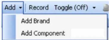
- Select

to create a new palette file.
- Then choose to either add a new brand or component (to all brands).
Or right click on the brand/component list on the left side of the palette editor to add a brand or component (to a specific brand selected or to all brands on the list).
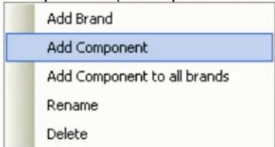
The new component will show up on the list along with RS232, XIR1 and XIR2 palettes added by default. Note: The XTR39 does not support RS232 commands. The XTR39 will learn IR commands in the XIR2 format.
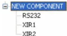
Choose the palette to work with and then edit the list of commands as needed.
PLACING COMMANDS ONTO THE GTL's (Creating Macro's)
All of the IR Codes (Palettes or IR Command Groups) should be confirmed and tested before continuing. In the sections to follow, you will be setting up the XTR39 for use in controlling a source. This will consist of setting up the Source Icons, placing IR commands onto the XTR39.
Selecting IR Palettes from the IR Code Library
- Click on PALETTE EDITOR on the right side XTR39 Dragon™ window if it is not already open.
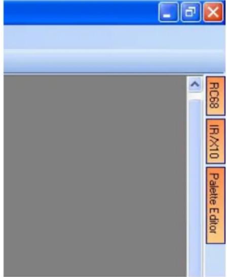

- Click on the mode button to change from "Mode: Edit" to "Mode: Palette"
- Click on the Manufacturer and then the Component Type (i.e. VCR, DVD etc.).
- Find the Command Group file previously tested
Selecting IR Palettes
Scroll the list (if necessary) and click on the component of each palette you need for your system (i.e. Pioneer CD, RCA DSS, etc).
As you click on each file name, the palettes will appear side-by-side, left to right, with the filename in each title bar.
NOTE 1: The various palettes and window boxes can be moved and sized (except the virtual keypads) for ease of use. If you click on a Palette file in the list and you do not see it on the screen, move some of the currently opened windows to see if it is hidden behind another window.
NOTE 2: Each palette can be edited by clicking the Edit Palette bar or closed with the X button in the title bar.
Associating Commands To GTL's (Drag And Drop Commands)
- Select the MACRO's tab in the XTR39 window
- Click the desired Source button on the XTR39 GUI Display.
- Click the Function button you wish to place a command under and select the applicable command from the palette editor window for that component function. The code name (function/brand/component) for that button will appear in the Macro Command List on the window.
- To add additional commands to the same button (i.e. creating a Macro Sequence), just repeat steps 2 & 3. Up to 40 Commands can be placed under each programmable button.
- Repeat for all GTL Function buttons, Source Buttons, and hard buttons.
Timed Delays
Timed Delays can be placed in a sequence. This is desired in macros where a delay is needed between two commands to allow for a unit to respond completely to the previous command (i.e. After a POWER ON command is given a Delay is usually necessary before the next command will be recognized or when entering multiple digit channel commands to a CBL or SAT box).
-
Click the up/down arrows next to the "DELAY" graphic in the Macro Command List window for the number of seconds you want up to 30 seconds (i.e. 2 = 2 seconds) or simply highlight the number in the Delay window and enter the number using the keyboard.
-
Right click on the delay clock icon placed on the Command List.
NOTE: As you drag a command upward in the list and you want the command between two existing commands, drop it on the lower one. As you drag downward, drop it on the upper one.
Delete
Highlighting a single command in the Macro Command List and right-click the command with the mouse. Selecting Delete from the pop-up menu will remove the command from the Macro Command List.
Testing Commands Placed on the virtual XTR39 Window
Commands placed under buttons in the virtual XTR39 window may be tested prior to downloading. To test commands, the PC must be connected to the XTR39 and the XTR39 must be pointed at the source to be controlled.
In XTR39 Dragon, under the menu items, change from Normal Mode to Test Mode.
Select the appropriate GTL button in the XTR39 window with the IR codes placed under it to test. (i.e. PLAY button). The button should now appear selected.
Commands listed under the Macro Command List for that selected Command should now be executed in order of appearance.
TRANSFERRING THE PROJECT
The project can now be transferred to the XTR39.
NOTE: Before continuing, make sure the PC is connected to the XTR39 and a 'BASE UNIT WHO AM I' can be performed.
To transfer the project to the XTR39, complete the following steps.
- Click on BASE UNIT and select 'Who am I...', and "XTR39" from the menu list. Verify a valid response is received.
- Click on FILE and select 'Transfer Project' from the menu list or simply press CTRL + B on the PC keyboard.
- A file transfer dialog box should appear and start showing progress of the transfer process.
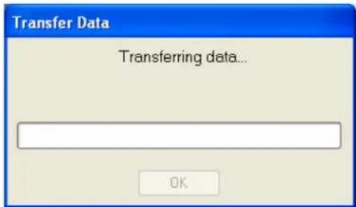
-
A spinning wheel will appear on the XTR39. This indicates project data from the PC is being transferred to the XTR39. Do not disturb the connection between the PC and XTR39 until the transfer is complete.
-
The XTR39 will automatically restart with the newly create project.
Congratulations, you have finished programming the XTR39!
MAINTENANCE
Firmware Update
To access the latest firmware updates, proceed to www.xantech.com and download the latest file. Place the downloaded file in an easy to locate directory.
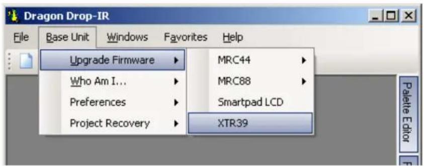
- Launch XTR39 Dragon and connect the XTR39 to the computer via the USB port.
- Go to menu item "Base Unit". Then select "Upgrade Firmware" and then "XTR39".
- A new "OPEN" window will appear. Select the firmware version to be updated.
Cleaning the XTR39
For safety reasons, disconnect the battery before cleaning.
- On the exterior surface, wipe gently using a damp cloth and then dry the surface.
- On the LCD screen, wipe gently using a soft cloth. It is recommended to use an optical type cleaning cloth.
- The contacts that engage the docking cradle should remain free of dirt and debris. With the unit disconnected from power, clean the contacts using a dry cloth or cotton swab.

Do not use solvents or other chemicals. Doing so will damage the XTR39.
Rechargeable Battery Maintenance
CAUTION
Danger of explosion if battery is incorrectly replaced.
Replace only with the same or equivalent type recommended by the manufacturer.
Dispose of used batteries according to the manufacturer's instructions. Please contact the manufacturer for these instructions.
FCC NOTICE
* Section 15.19 Labeling requirements
This device complies with part 15 of the FCC rules.
Operation is subject to the following two conditions:
(1) This device may not cause harmful interference and
(2) This device must accept any interference received, including interference that may cause undesired operation.
* Section 15.21 Information to user The changes or modifications not expressly approved by the party responsible for compliance could void the user's authority to operate the equipment.
* IMPORTANT NOTE: To comply with the FCC RF exposure compliance requirements, no change to the antenna or the device is permitted. Any change to the antenna or the device could result in the device exceeding the RF exposure requirements and void user's authority to operate the device.
ACCESSORY ITEMS
Xantech offers the following accessory items for the XTR39:
XTR39BTRY. Lithium-Ion battery for the XTR39.
XTR39CRDL. Cradle and power supply for the XTR39.
WARRANTY INFORMATION
REPAIRS:
TECHNICAL SUPPORT PRE-AUTHORIZATION
Certain products require a Pre-Authorization from our Technical Support Department prior to a Return Authorization (RA) being issued. Please call our Technical Support Department at 800 843-5465 Extension 301. Technical Support will transfer your call to the Sales Department to complete the TRA process.
LIMITED WARRANTY
Xantech warrants its products to be free of defects in materials or workmanship. This warranty extends for one year from the date of purchase by the consumer. Any products returned freight prepaid to Xantech and found to be defective by Xantech within the warranty period will be repaired or replaced, at Xantech's option, at no charge. Xantech will not be responsible for the actual cost of installation or removal of the product, nor for any incidental or consequential damages. Some states do not allow the exclusion or limitation of incidental or consequential damages so the above limitation or exclusion may not apply to you. This warranty gives you specific legal rights. You may have additional rights which vary from state to state.
Xantech Corporation
13100 Telfair Avenue, 2/F
Sylmar, CA 91342
XTR39 Hand-Held LCD Remote Control Installation Instructions © 2006 Xantech Corporation
This document is copyright protected. No part of this manual may be copied or reproduced in any form without prior written consent from Xantech Corporation.
Xantech Corporation shall not be liable for operational, technical, or editorial errors/omissions made in this document.
Document Number 08905073X5
- ATTENTION:
- INTRODUCTION 5
- PRELIMINARY SETUP 7
- PROGRAMMING SETUP 11
- INSTALLING AND CONFIGURING THE XTR39 DRAGON™ SOFTWARE 16
- STARTING A PROJECT....20
- CREATING THE GRAPHICAL USER INTERFACE (GUI)....21
- LEARNING IR COMMANDS (CREATING PALETTE FILES) 28
- PLACING COMMANDS ONTO THE GTL'S (CREATING MACRO'S) 34
- TRANSFERRING THE PROJECT....37
- FCC NOTICE 39
- ACCESSORY ITEMS 40
- WARRANTY INFORMATION 40
- INTRODUCTION
- XTR39 Overview
- XTR39 Features
- Box Contents
- PRELIMINARY SETUP
- Charging the XTR39 and Charging Cradle LED Indicator
- SYSTEM SETUP
- Display Settings - Backlight Adjustment
- Display Settings - Contrast Adjustment
- Display Settings - Backlight Timeout
- System Settings - Audio Feedback
- System Settings - Motion Detect
- Touch-screen Calibration Adjustment
- Touch-screen Calibration Test
- PROGRAMMING SETUP
- XTR39 Dragon™ Installation Guide
- Requirements:
- Installation
- CONFIGURING THE XTR39 Dragon™ SOFTWARE
- Starting XTR39 Dragon™ Software
- USB Connection
- Configuring USB Port
- Verifying PC to XTR39 Communication
- STARTING A PROJECT
- CREATING THE GRAPHICAL USER INTERFACE (GUI)
- Choosing A Style
- Backgrounds
- Building a Page (Working with GTL's)
- Placing Source GTL's
- Placing Function Button GTL's
- Inserting Additional Pages for a Single Source
- Editing GTL Properties
- Creating Labels (GuiFX Transports and Icons)
- Inserting Labels
- LEARNING IR COMMANDS (Creating Palette Files)
- Built-In IR Code Library
- Testing IR Commands in the IR Library
- Learning IR Commands (XIR2)
- Using the Palette Editor
- Editing Function Names in the Palette Editor
- Testing IR Commands in the Palette Editor
- Creating a Palette File
- PLACING COMMANDS ONTO THE GTL's (Creating Macro's)
- Selecting IR Palettes from the IR Code Library
- Selecting IR Palettes
- Associating Commands To GTL's (Drag And Drop Commands)
- Timed Delays
- Delete
- Testing Commands Placed on the virtual XTR39 Window
- TRANSFERRING THE PROJECT
- MAINTENANCE
- Firmware Update
- Cleaning the XTR39
- Do not use solvents or other chemicals. Doing so will damage the XTR39.
- Rechargeable Battery Maintenance
- CAUTION
- FCC NOTICE
- ACCESSORY ITEMS
- WARRANTY INFORMATION
- REPAIRS:
- LIMITED WARRANTY
Brand : Xantech
Model : XTR39
Category : Controller