VD-21IRVF - Security Camera Comtrend - Free user manual and instructions
Find the device manual for free VD-21IRVF Comtrend in PDF.


| Product Type | Security Camera |
| Brand | Comtrend |
| Model | VD-21IRVF |
| Image Sensor | 1/2.8" Progressive Scan CMOS |
| Resolution | 1920 x 1080 (Full HD) |
| Frame Rate | Up to 30 fps |
| Lens | 2.8 mm fixed lens |
| Field of View | Horizontal: 90°, Vertical: 50° |
| IR Range | Up to 30 meters (98 ft) |
| Minimum Illumination | 0.01 Lux (color), 0 Lux with IR |
| Audio | Built-in microphone and speaker |
| Power Supply | 12V DC, PoE (802.3af) |
| Power Consumption | Max 7W |
| Dimensions (W x H x D) | 70 mm x 180 mm x 70 mm |
| Weight | Approx. 350 g |
| Weatherproof Rating | IP67 (dust and water resistant) |
| Operating Temperature | -30°C to 60°C (-22°F to 140°F) |
| Storage Temperature | -40°C to 70°C (-40°F to 158°F) |
| Network Interface | 1 x 10/100 Mbps Ethernet (RJ45) |
| Wireless | IEEE 802.11 b/g/n (2.4 GHz) |
| Supported Protocols | TCP/IP, HTTP, DHCP, DNS, RTSP, ONVIF |
| Video Compression | H.265 / H.264 / MJPEG |
| Motion Detection | Yes, with customizable zones |
| Two-Way Audio | Supported via built-in mic and speaker |
| SD Card Slot | MicroSD up to 128 GB (local storage) |
| Compliance | CE, FCC, RoHS |
Frequently Asked Questions - VD-21IRVF Comtrend
User questions about VD-21IRVF Comtrend
0 question about this device. Answer the ones you know or ask your own.
Ask a new question about this device
Download the instructions for your Security Camera in PDF format for free! Find your manual VD-21IRVF - Comtrend and take your electronic device back in hand. On this page are published all the documents necessary for the use of your device. VD-21IRVF by Comtrend.
USER MANUAL VD-21IRVF Comtrend
natural_image
Close-up of a white surveillance camera with a circular lens and multiple camera modules (no visible text or symbols)User Manual

CONTENTS
Chapter I.
Overview
1.1. Read Before Use 1
1.2. Physical Description 2
1.3. Safety Instructions 4
1.4. Package Contents 5
1.5. Electromagnetic Compatibility 6
Chapter 2.
Installation
2.1. Hardware Installation 7
2.2. SMAX Finder Installation 8
2.3. Ready to Use 9
Chapter 3.
Accessing
3.1. Network Deployment 10
3.2. Using Web Browsers 14
3.3. Using RTSP Players 15
3.4. Using Mobile APP 16
3.5. Using VMS 17
Chapter 4.
WEB UI
4.1. Main Page 22
4.2. Client Settings 23
Chapter 5.
Configuration
5.1. System Setup 24
5.2. Network Setup 28
5.3. Video & Audio Setup 38
5.4. SD Card Setup 51
5.5. Event Setup 55
5.6. Maintenance 61
5.7. Device info 64
CONTENTS
Chapter 6.
Appendix
6.1. URL Commands 66
6.2. Technical Specifications 81
6.3. Onvif Supports List 8 3
6.4. Liability 9 4
6.5. Copyright 95
Chapter I.
Overview
1.1. Read Before Use
This network camera is a professional equipment for surveillance purpose. Please comply with each national laws to prevent from any relevant privacy violations before use.
In order to operate this network camera, it require a basic knowledge of network structure. For further use of project application, it requests an advance level of knowledge in lens optics selection, network structure design, storage planning and software capability.
This product service may be different since the diversity of distributors. We suggest to purchase SMAX product from SMAX direct distributors or system integrators to get the most complete after service.
Please first check the package contents are complete with nothing missing. Then, carefully read through all attentions and instructions before use.
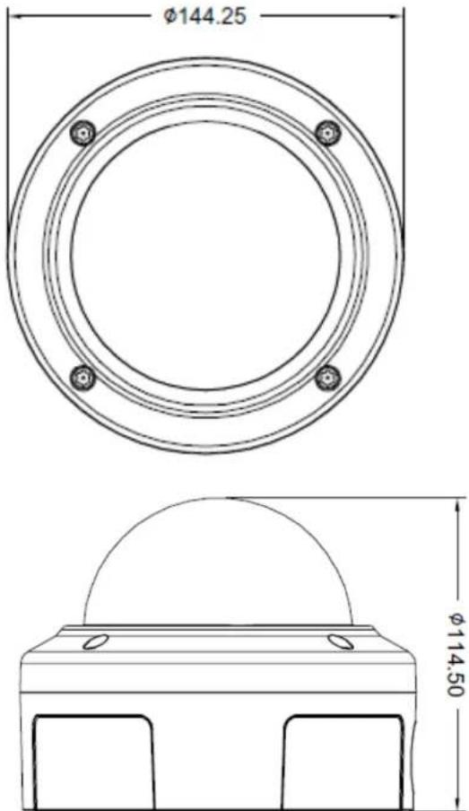
Chapter I.
Overview
1.2. Physical Description
1.2.1. Mechanical and hardware interface
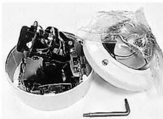
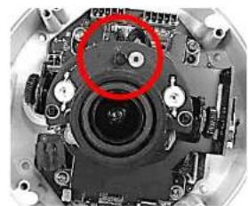
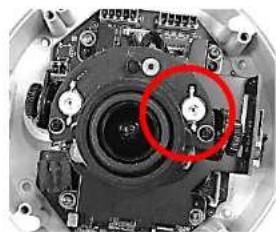
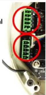
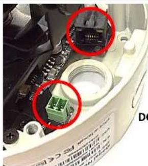
GV1 is built in with motorized lens network camera. Its light sensor can detect and control the IR-LED On/Off. Along side with the Zoom In/Out function from the motorized lens, it will get the most balance IR-LED light.
GV1 accepts both POE or DC 12V as power supply. Please noted that the DC 12V adapter is an extra accessory which does not include in this package.
GV1 supports two ways audio function which can connect with an external speaker and microphone.
GV1 has micro SD/SDHC card slot built in for recording storage function.
natural_image
Disassembled electronic components in a circular housing, partially covered by plastic wrap and wrench (no text or symbols visible)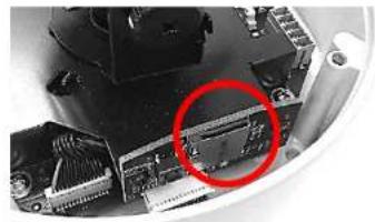
natural_image
Close-up of a computer motherboard with a red circle highlighting a component (no visible text or symbols)MicroSD/SDHC Card Slot
natural_image
Close-up of a mechanical assembly with a red circle highlighting a component (no visible text or symbols)Light Sensor
natural_image
Close-up of a mechanical camera module with a red circle highlighting a component (no visible text or symbols)IR LED
DIDO
Terminal
Block
natural_image
Close-up of a mechanical component with red circles highlighting two green connectors (no visible text or symbols)Ethernet 10/100 RJ45 port
COMTREND
www.comtrend.com
Chapter I.
Overview
1.2. Physical Description
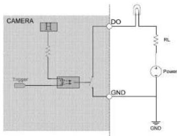
1.2.2. Digital Input (DI)
| ItemDescription | |
| 1 | DI |
| 2 | GND |
| Digital Input | ||
| PinNotes | Specifications | |
| Trigger is “Off”, DO connect to GNDTrigger is “On”, DO is floating | Max load:30mA,30VDC | |
Chapter I.
Overview
1.3. Safety Instructions
Carefully read through the safety instruction below.
●Network cameras are delicate. Handle with care.
- Do not store the camera in a high temperature or high humidity location. Avoid direct sun light.
- Keep away from children.
- Do not disassemble the camera. No serviceable components inside.
- When placing a camera in a high humidity or wet environment, select a product with an IP66/67 level weather proofing rating.
- Cameras will generate heat during normal operation. Avoid direct contact with hot camera components during or after operations.
- Do not attach DC/AC power directly to the camera's DI/DO port.
- Check the correct direction when inserting the Micro SDHC card into camera's Micro SDHC card slot.
- Contact your sales channel or find a regional Comtrend distributor for any warranty issues.
Chapter I.
Overview
1.4. Package Contents
| Description Qty | |
| Network Camera 1 | |
| Tools package (Screw Kit...etc.) 1 | |
| CD:A. Software:Comtrend Finder x 1B. Doc:Datasheet,User Manual,Quick Installation Guide | 1 |
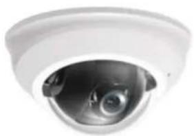
natural_image
Close-up of a white surveillance camera lens showing the aperture (no text or symbols visible)Network Camera

CD
Chapter I.
Overview
1.5. EMC (Electromagnetic Compatibility)
FCC Statement
This device compiles with FCC Rules Part 15. Operation is subject to the following two conditions.
(1.) This device may not cause harmful interference, and
(2.) This device must accept any interference received, including interference that may cause undesired operation.
This equipment has been tested and found to comply with the limits for a Class A digital device, pursuant to Part 15 of the FCC Rules. These limits are designed to provide reasonable protection against harmful interference when the equipment is operated in a commercial environment. This equipment generates, uses, and can radiate radio frequency energy and, if not installed and used in accordance with the installation manual, may cause harmful interference to radio communications. Operation of this equipment in a residential area is likely to cause harmful interference, in which case the user will be required to correct the interference at his own expense.
CE Mark Warning
This is a Class A product. In a domestic environment, this product may cause radio interference, in which case the user may be required to take adequate measures.


COMTREND
www.comtrend.com
Chapter 2.
Installation
2.1. Installation
Follow the instructions below to setup your network camera.
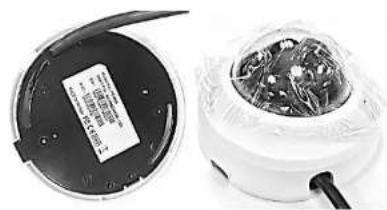
Setup 1.
Push the housing release tab and remove the cover. Insert a Micro SD card (Optional) for on device storage.
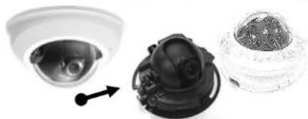
natural_image
Three different types of surveillance cameras shown from different angles (no text or symbols visible)Setup 2.
Fix the camera on the wall or ceiling with supplied screws and twist the camera to the desired viewing angle.
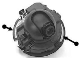
natural_image
Close-up of a mechanical device with no visible text or symbolsSetup 3.
Adjust the tilt angle and focus as necessary.
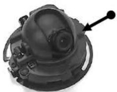
natural_image
Close-up of a mechanical device with a circular component and an arrow pointing to it (no visible text or symbols)Setup 4.
Connect the camera to a *PoE switch or *PoE injector.
Make sure the network connection is stable.
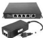
*. This network camera can only use PoE power.
Setup 5.
Connect the network cable to the camera.
PoE (RJ-45)
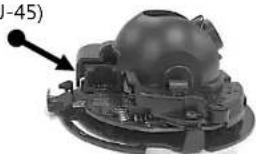
natural_image
3D rendered mechanical component with a highlighted section and arrow indicator (no text or symbols)Setup 6.
Re-mount the cover.
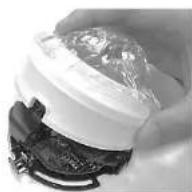
Setup 7.
Make sure to keep the camera cover closed and the network cable output fed through the desired path.
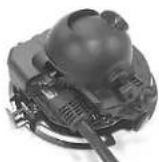
natural_image
Two views of a remote control device showing a circular lid and a spherical display with internal components (no visible text or symbols)COMTREND
www.comtrend.com
Chapter 2.
Installation
2.2. Comtrend IPFinder Installation
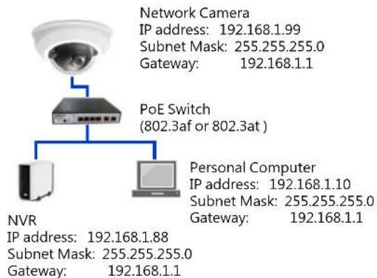
A basic camera setup diagram is shown on the right: (In a normal application, the camera only needs to be within a local LAN structure to meet the surveillance requirement.)
Comtrend Finder Installation :
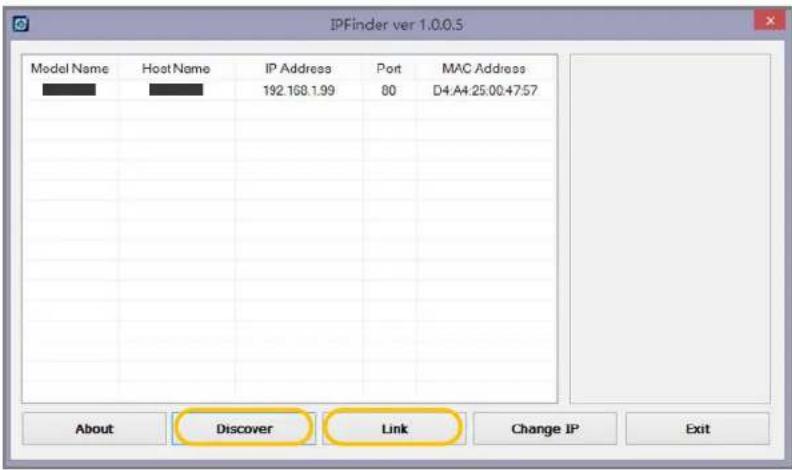
Read the CD from the package content. Then copy IPFinder.exe file to your personal PC. Run the program until the Finder windows display as shown on the right picture.
Comtrend Finder procedure :
Step 1.
Press the "Discover" button so the program will search for all Comtrend IP cameras within the local network.
Step 2.
Choose a specific camera, then press the "Link" button. The program will launch the default browser and initiate connection to the camera's web UI access page.
Notification:
Comtrend camera default IP setting is DHCP mode.
Default IP address is 192.168.1.99. (if No DHCP Service)
Default username and password is both admin.
flowchart
graph TD
    A["Network Camera"] --> B["PoE Switch (802.3af or 802.3at)"]
    B --> C["NVR"]
    B --> D["Personal Computer"]
    style A fill:#f9f,stroke:#333
    style B fill:#ccf,stroke:#333
    style C fill:#cfc,stroke:#333
    style D fill:#fcc,stroke:#333
Chapter 2.
Installation
2.3. Ready to Use
Access procedure:
Step 1.
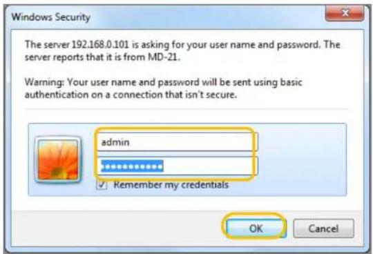
When linked from Comtrend's Finder to the camera's web UI access page, enter the default username and password (ID: admin / PW: admin) for further access.
Step 2.
When first connecting to a Comtrend camera, some plugin need to be installed on to your computer. Follow the instruction and press allowed to allow the installation to proceed.
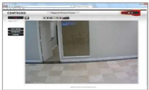
Step 3.
After installation of ActiveX plugin, you should be able to see the video stream from camera as shown on the below picture.
COMTREND
www.comtrend.com
Chapter 3.
Accessing
3.1. Network Deployment
Comtrend cameras support both intranet and internet structures.
A. True IP address setting
B. Transfer from UPnP router
C. PPPoE connection setting
Structure as shown on the right
Step 1.
Run the IPFinder and search the local network for Comtrend cameras.
Step 2.
Enter you static true IP address which was provided by your ISP. Then press enter.
Notification :
Please contact your ISP vender for further static true IP address setting or service.
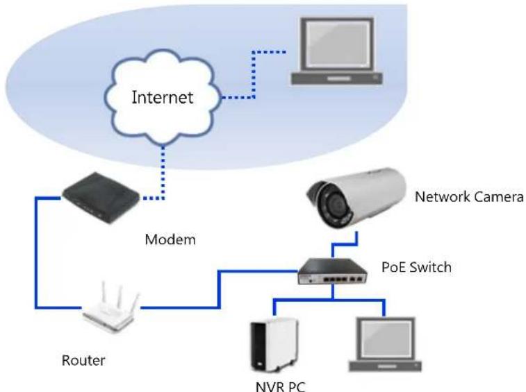
flowchart
graph TD
    A["Internet"] --> B["Modem"]
    B --> C["Router"]
    C --> D["PoE Switch"]
    D --> E["NVR PC"]
    D --> F["Network Camera"]
    G["Computer"] --> A
Notification :
When you have a true IP address, you may need set your camera to a static IP address. Then you may use an internet browser by entering this static true IP address to access your network camera.
If your true IP address is going to your router, you may need to use port forwarding. This is the solution that solves the problem when a surveillance project lacks a true IP address for management. The performance of the camera will be strongly dependent on the performance of the router. It may cause an abnormal connection.
Chapter 3.
Accessing
3.1. Network Environment Setting
A. True IP address setting
Step 1.
Run the Comtrend IPFinder and search for the camera within the local network.
Step 2.
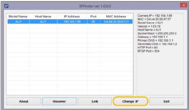
Select the camera and click "Change IP" button.
Step 3.
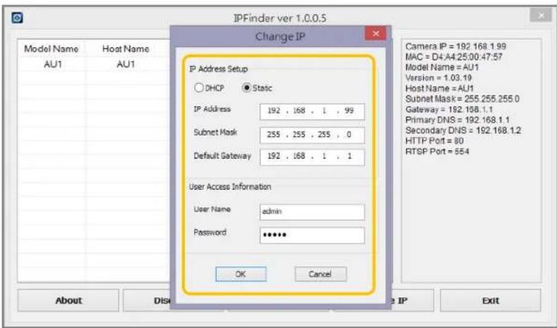
Select static mode and enter your true IP address, Subnet mask, Default gateway, and the username and password of the camera. Then press "OK" to finish.
Once complete, the "Change IP Success!" message will display.
Notification :
Please contact your ISP vender for further static true IP address setting or service.
Chapter 3.
Accessing
3.1. Network Environment Setting
A. Transfer from UPnP router
Step 1.
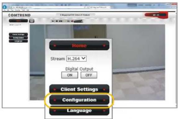
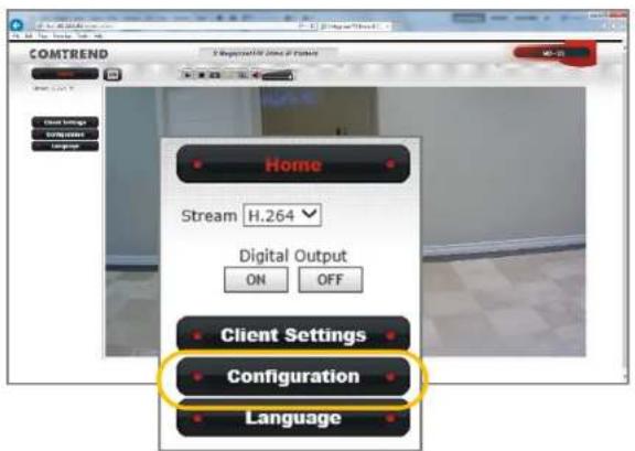
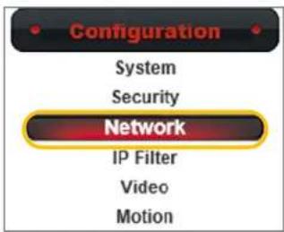
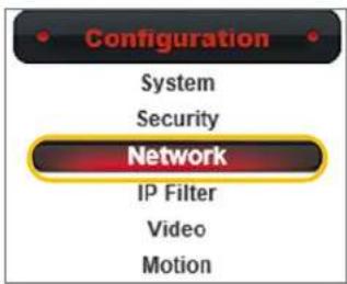
Access to the camera's web UI page and select the "Configuration" option.
Step 2.
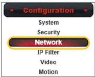
Select the "Network" option.
Step 3.
Assign a static IP address the fits your local network, then enter your gateway address and DNS information.
Step 4.
Select "Enable UPnP Discovery" and "Enable UPnP Port Mapping". Then press the "Apply" button to apply the setting.
Notification :
Network camera's UPnP function may have some compatible issue with certain routers. For your specific router refer to your router's instruction manual about Port Forwarding and other UPnP setting.
![COMTREND 2 Megapixel FIX Dome IP Camera MD-21 Home Client Settings Configuration System Event Video Audio Motion Privacy Mask Event Recording SDHC Log Device info Maintenance Language Network General Advanced Network type LAN DHCP IPv4 DHCP IPv4/IPv6 Static IPv4/IPv6 IP Address(IPv4) 192.108.0.101 IP Address(IPv6) Prefix Length 6:1 * number result by between IPv20L Subset Hack 250.255.255.0 Gateway 192.168.0.1 Primary DNS 4.2.2.2 Secondary DNS 4.2.2.1 Enable UPnP Discovery Enable UPnP Port Mapping HTTP port 80 RTSP Port 554 RTP Data Port 5026 Port If you are using HTTP, be sure to enable HTTP Services[Event > Event server] to receive HTTPs if address through email.](/content/2026/05/1001684/images/afa39fc15f4f2a3e54e023b7fc15d69c8706114c6a84a8ffb43667b2aa17cdbd.jpg)
Chapter 3.
Accessing
3.1. Network Environment Setting
A. PPPoE connection setting
Step 1.
Access to the camera's web UI page and select the "Configuration" option.
Step 2.
Select the "Network" option.
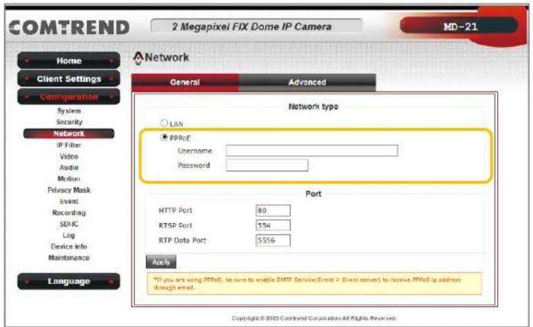
Step 3.
Select "PPPoE" and enter your username and password. Then press the "Apply" button to finish.
Notification :
When select PPPoE connection, make sure your network camera is equipped with a true static IP address. If so, you can access to the camera by entering the IP address via internet. If not, refer to our DDNS setting.
COMTREND
www.comtrend.com
Chapter 3.
Accessing
Comtrend Network Camera connection :
Comtrend's network cameras support multiple connections for accessing. Including multiple browsers connection, video player connection that supports RTSP, and NVR access. Each connection fulfill different surveillance application for different purposes.
3.2. Accessing via Web UI
You can choose to view the Comtrend camera UI with a web browser to view live video, SD card recording and searching, local computer recording, audio functions and other advanced features.
Notification :
1) We suggest to use IE 9/10/11 and above version to access the Comtrend network camera.
2) Other than IE browser, Comtrend network cameras also support both Google Chrome and Mozilla Firefox browsers for accessing.
3) If using Google Chrome and Mozilla Firefox to access, those browsers will need Quick Time to play the live video. If your computer has not install Quick Time software, download and install it prior to viewing the Comtrend camera UI.
![COMTREND 100% 100% 100% 100% View: [23] Top View Bottom View Top View](/content/2026/05/1001684/images/166e8aa4cc3ffcf6cac076554a7f17a39b20991716e214d2dcb84d2aa8507770.jpg)

Windows®
Internet Explorer

chrome

mozilla
Firefox
Chapter 3.
Accessing
3.3. Accessing via RTSP Player
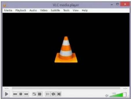
Comtrend network cameras support accessing via RTSP player. Below using VLC player as a reference instruction:
Step 1.
Run the VLC player and select the "Media(M)" button. Then select "Open network stream(N)". It will pop out the settings window.
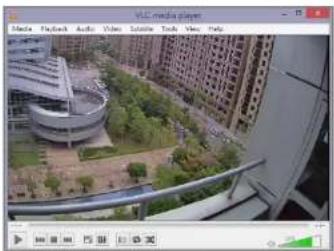
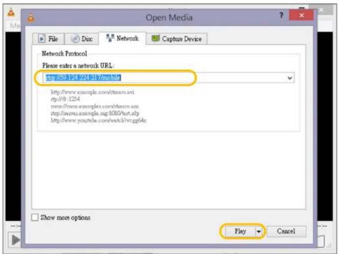
Step 2.
Enter the RTSP address "ex. rtsp://Camera's IP/stream1" and press the "Play" button. It should link to the camera for the live video as shown in below picture.
Notification :
Comtrend network cameras provide three RTSP stream: Main stream address: rtsp://Camera's IP/stream1 Second stream address: rtsp://Camera's IP/stream2 Mobile stream address: rtsp://Camera's IP/mobile
natural_image
Exterior view of a modern urban area with curved architecture and surrounding residential buildings (no visible signage or text)COMTREND
www.comtrend.com
natural_image
VLC media player interface showing a traffic cone on a black background (no text or symbols on the cone itself)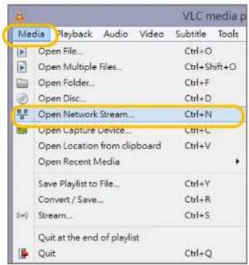
Chapter 4.
WEB UI
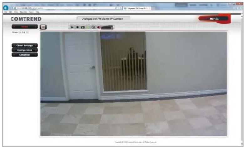
4.1. Home page
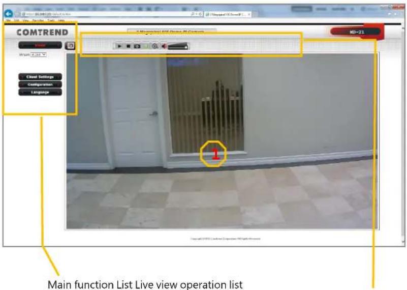
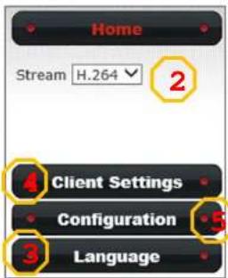
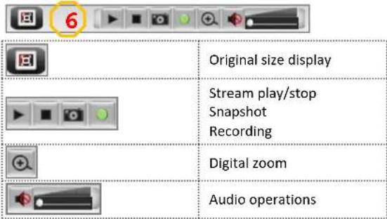
You can access the Comtrend network camera via a web browser to monitor live view, manage setting, SD card recording...etc. There is a complete introduction procedure of all function in the following chapters.
Function list of icons is shown on the picture to the right.
COMTREND
www.comtrend.com
Chapter 4.
WEB UI
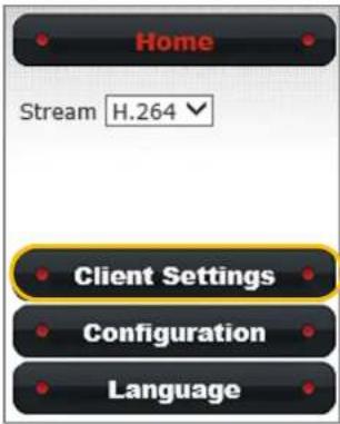
4.2. Client Settings
4.2.1. Protocol options
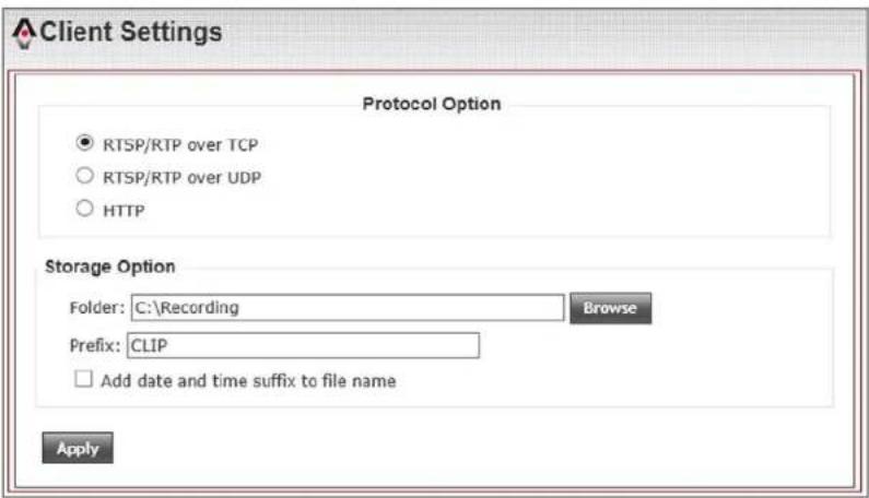
This setting is to define your protocol option. Default is set as RTSP/RTP over TCP. This protocol make sure that all image data must be transferred. But if you choose the image quality comes first, then you can change to RTSP/RTP over UDP. If your network environment only allows to connect with web page, then you can change to HTTP protocol.
4.2.2. Storage Options
This setting is to define your storage option. When doing a recording action, you can set where the recording file saves to. Press the "Browse" button to set your folder path. You can also name the Prefix of recording file and select to "Add date and time suffix to file name". Press "Apply" to save.
Chapter 5.
Configuration
5.1. Configuration Settings
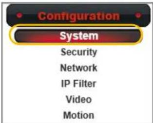
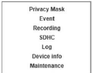
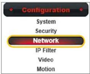
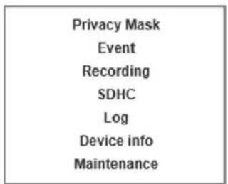
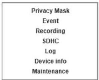
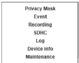
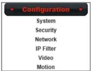
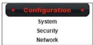
In the configuration menu, it includes all operating functions for settings, maintenance, log and device information...etc.
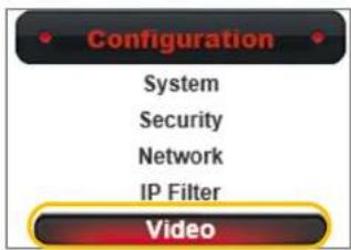
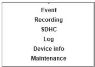
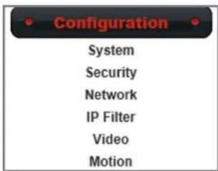
Configuration menu as shown below :
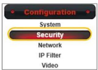
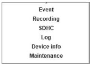
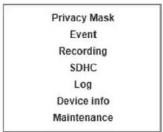
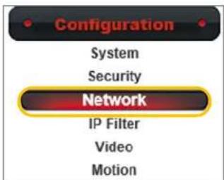
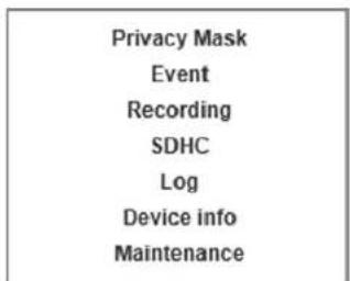
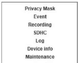
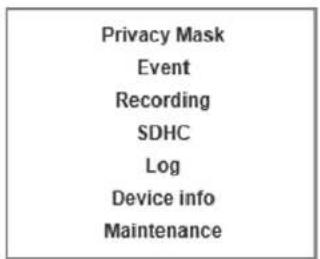
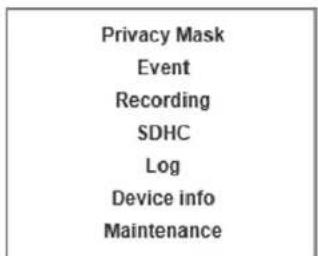
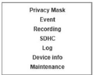
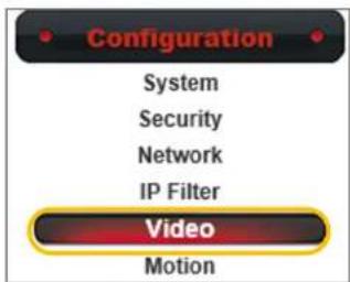
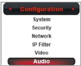
1) System
2) Security
3) Network
4) IP Filter
5)Video
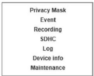
6)Audio
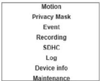
7) Motion
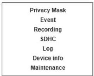
8) Privacy Mask
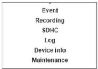
9) Event
10)Recording
11)SDHC
12)Log
13) Device Info
14) Maintenance
| Configuration |
| System |
| Security |
| Network |
| IP Filter |
| Video |
| Audio |
| Motion |
| Privacy Mask |
| Event |
| Recording |
| SDHC |
| Log |
| Device info |
| Maintenance |

COMTREND
www.comtrend.com
Chapter 5.
Configuration
5.1. Configuration Settings
5.1.1. System
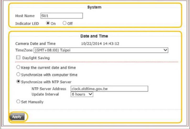
This system page displays your network camera's Host Name, LED Indicator ON/OFF Switch and set the Date and Time.
Date and Time Setting procedure :
Step 1.
Select your network camera's Time Zone and enable Daylight Saving if desired.
Step 2.
There are four ways to synchronize the camera's time: Keep the current date and time, Synchronize with computer time, Synchronize with NTP Server and Set Manually.
For a small surveillance system, we suggest Synchronize with computer time. Press the "Apply" button to save settings.
Step 3.
For a medium or larger surveillance system, we suggest to Synchronize with NTP Server. Enter your NTP Server Address and set the Update Interval. Then press "Apply" to save settings.
System
COMTREND
www.comtrend.com
Chapter 5.
Configuration
5.1. Configuration Settings
5.1.2. Security
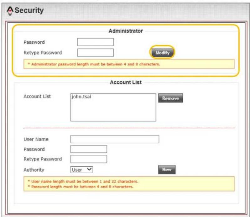
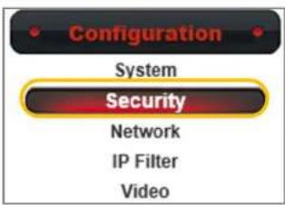
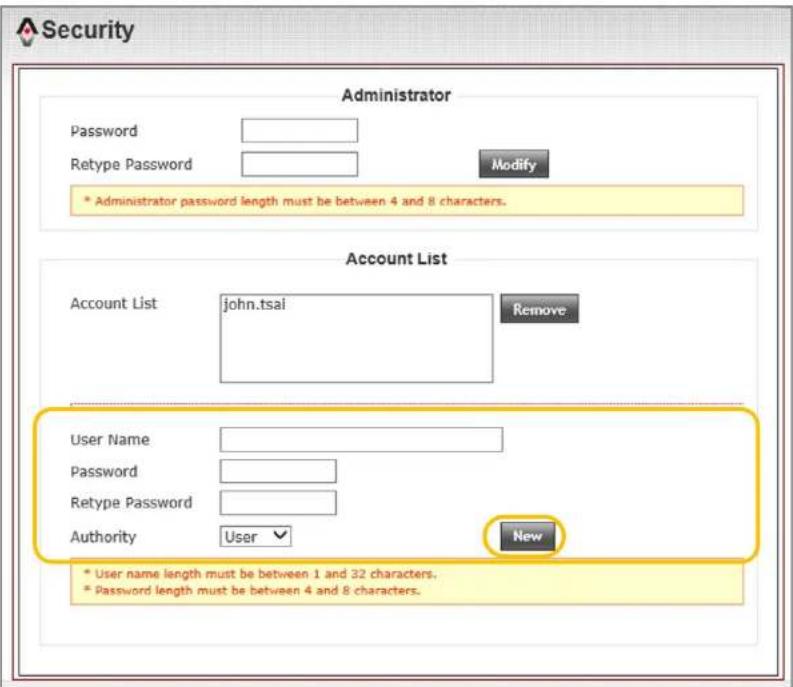
Select the "Security" button under the "Configuration" menu. This function is to manage the Users of the camera by setting Administrator and Account List.
Administrator Setting Procedure :
Step 1.
Enter a new Password and Retype Password.
Notification :
Administrator password can be a composition of letters and numbers. But the length must kept between 4 and 8 characters. No special character are allowed. The password is case sensitive.
Step 2.
Press the "Modify" button to save the settings.
Chapter 5.
Configuration
5.1.2. Security
Account List Setting Procedure :
Step 1.
Enter a Username, Password, Retype Password.
Notification :
Username can be a composition of letters and numbers. The length must kept between 1 and 32 characters. No special character are allowed. The Username is case sensitive.
User password can be a composition of letters and numbers. The length must kept between 4 and 8 characters. No special characters are allow. The password is case sensitive.
Step 2.
Select "Authority" then press "New" to add an account.
Notification :
Authority has two types, "User" or "Guest". The privilege of a guest is limited to watch the live view from the home page only. A "User" is allowed to operate all function within the home page and modify the client setting. Access to configuration menu is limited to "LOG" and "Device Info".
Chapter 5.
Configuration
5.2. Network Settings
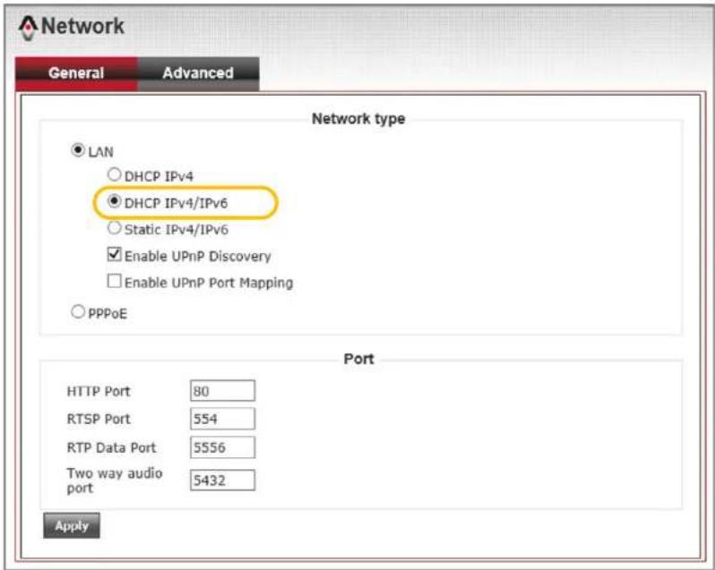
Default network settings of the camera are LAN type, DHCP IPv4/IPv6 and Enable UPnP Discovery. When this network camera is introduced to Local network environment, the camera will get a dynamic IP from the local DHCP server each time the camera turns on.
5.2.1. General Network Settings
5.2.1.1. General Network Settings Recommendation
We suggest to use Static IPv4/IPv6.
Camera's port setting as shown below :
a)HTTP Port : 80
b)RTSP Port : 554
c) RTP Data Port : 5556
Notification :
If the default setting cannot connects to network camera properly, consult with you network administrator.
Chapter 5.
Configuration
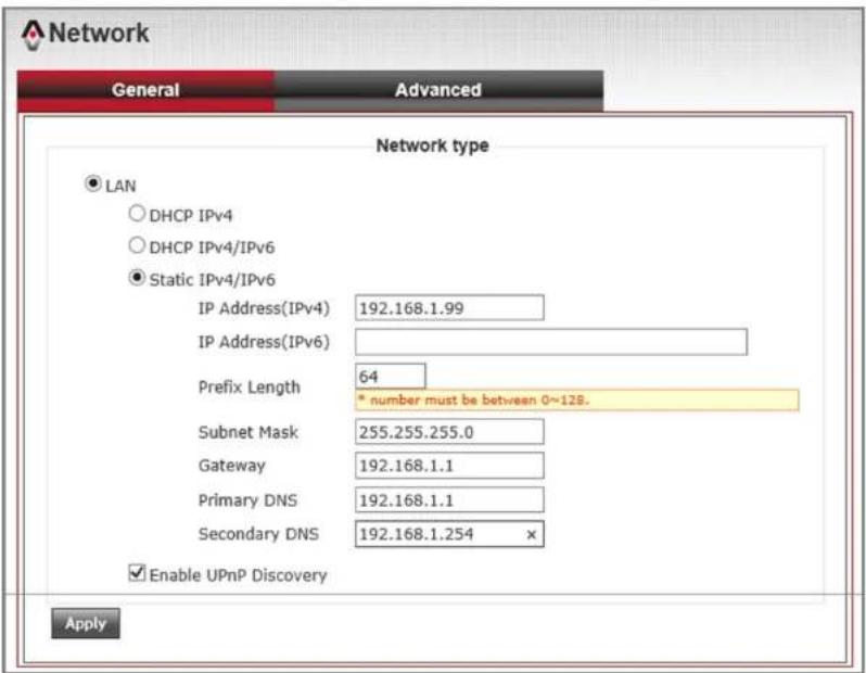
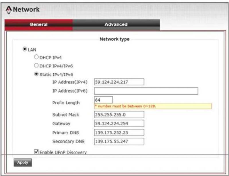
5.2.1.1. Intranet Static IPv4/IPv6 Setting Static IPv4 Setting Procedure :
Step 1.
Select "Static IPv4/IPv6" under "Network Type".
Step 2.
Enter an IP Address (IPv4), Subnet Mask, Gateway, Primary DNS and Secondary DNS settings.
Step 3.
Then press "Apply" to save settings.
Notification :
For static IP setting, refer to the pictures as shown on bottom right. If the LAN IP segment is 192.168.1.xxx. Enter your router's IP address for the Gateway.
COMTREND
www.comtrend.com
Chapter 5.
Configuration
5.2.1.2. Internet Static IPv4/IPv6 Setting Static IPv4 Setting Procedure :
Step 1.
Select "Static IPv4/IPv6" under "Network Type".
Step 2.
Enter the IP Address (IPv4), Subnet Mask, Gateway, Primary DNS and Secondary DNS settings.
Step 3.
Then press "Apply" to save settings.
Notification :
Please contact your ISP service vender for further internet static IP settings.
COMTREND
www.comtrend.com
Chapter 5.
Configuration
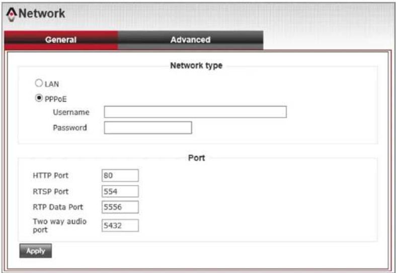
5.2.1.3. PPPoE Setting
PPPoE Setting Procedure :
Step 1.
Select "PPPoE" under the "Network Type" column.
Step 2.
Enter your PPPoE Username and Password.
Step 3.
Press "Apply" to save settings.
Notification :
PPPoE is a type that supports xDSL network connections. Contact your ISP service vender for the username and password.
For PPPoE connections, the network camera will get an IP Address from the ISP. Some ISP vendors may provide a static IP address. The User only needs to enter that IP in to their browser, then you will able connects to the network camera.
If your ISP vender does not supply PPPoE static IP addresses, refer to the DDNS setting in Advanced Network Setting.
Chapter 5.
Configuration
5.2.2. Advanced Network Setting
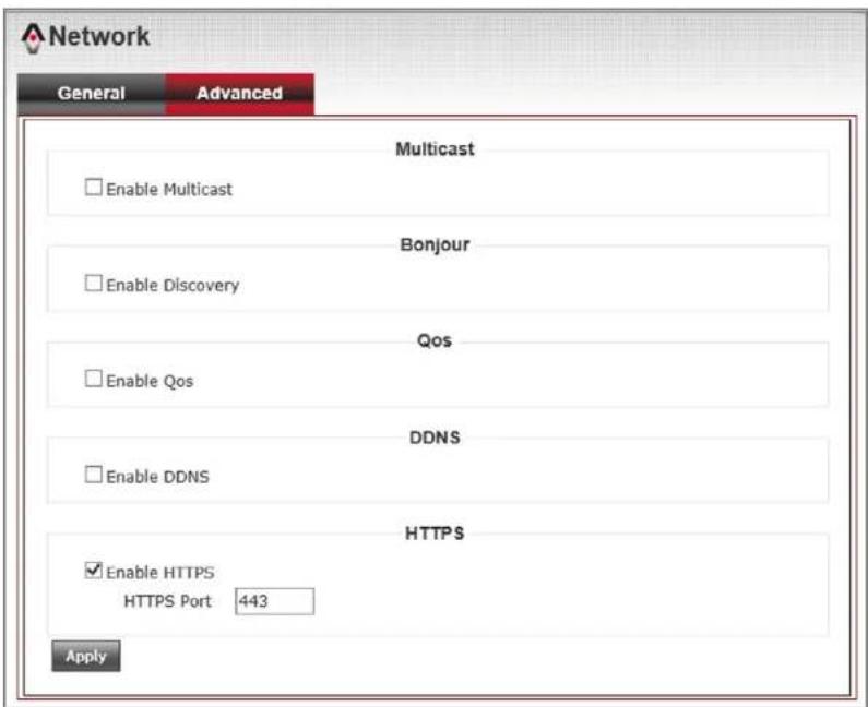
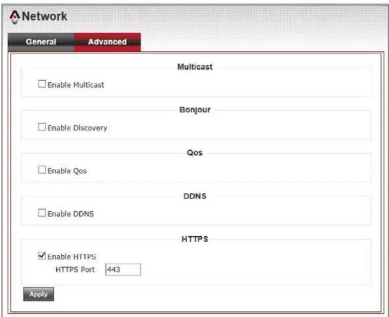
Advanced network setting includes Multicast, Bonjour, QoS, DDNS, HTTPS function settings.
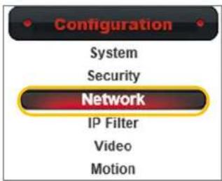
5.2.2.1. HTTPS Settings
HTTPS Settings Procedure :
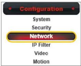
Step 1.
Select "Advanced" page under "Network" page.
Step 2.
Select "Enable HTTPS". Default HTTPS Port is 443.
Step 3.
Press "Apply" to save settings.
Chapter 5.
Configuration
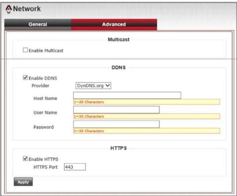
5.2.2.2. DDNS Settings
You must first get DDNS address settings from a DDNS service provider. That DDNS service provider should provide you with a Host Name, and let you know the Username and Password.
Notification :
Comtrend network cameras support two DDNS service providers: DynDNS.org and No-ip. You can choose either one of these services to host your DDNS Host Name.
DDNS Settings Procedure :
Step 1.
Select "Advanced" page under "Network" page.
Step 2.
Select "Enable DDNS". Then enter the Host Name, Username and Password.
Step 3.
Press "Apply" to save settings.
COMTREND
www.comtrend.com
Chapter 5.
Configuration
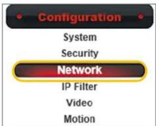
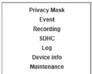
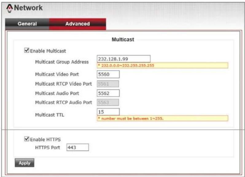
5.2.2.3. Multicast Setting
Multicast Description :
A normal connection between computer to network camera is a single point delivery. Which means sending a stream packet from camera to one computer only. A multicast function is to send the stream data to one point, but you can set multiple computer as the recipient.
Comtrend network cameras support multicast group addresses. It's IP address range is from 232.0.0.0 to 232.255.255.255 in a class D. A class D is a group address which the network camera will send the stream packet to. Then the recipient will inform the router to join this group.
Multicast Setting Procedure :
Step 1.
Select "Advanced" page under "Network" page.
Step 2.
Select "Enable Multicast". Then enter "Multicast Group Address" and all Multicast parameters. Suggest to keep the default setting.
Step 3.
Press "Apply" to save settings.
Chapter 5.
Configuration
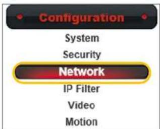
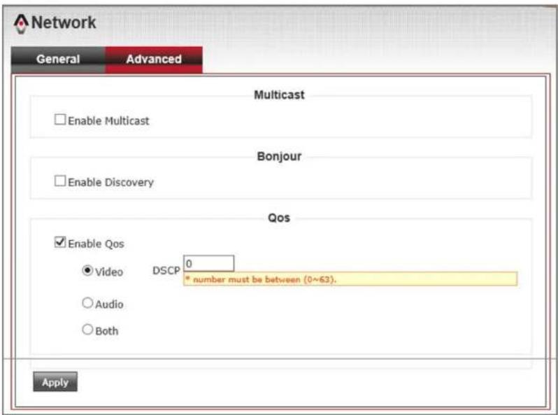
5.2.2.4. QoS Setting
Via QoS settings, the camera can ensure the video image and audio stream comes first in bandwidth. So the transfer stability will not be effected by other network packets.
QoS Setting Procedure :
Step 1.
Select "Advanced" page under "Network" page.
Step 2.
Select "Enable QoS". And select whether enable "Video", "Audio" or "Both", then enter its "DSCP value".
Step 3.
Press "Apply" to save settings.
Notification :
DSCP (Differentiated Services Code Point). In Dec. 1998, IETF published a QoS classification standard of Diff-Sery (Differentiated Service). DSCP using six bits and its range from 0\~63.
Chapter 5.
Configuration
5.2.2.5. Bonjour Setting
Bonjour is called a Zero-configuration networking tool, which can automatically find devices within local network. Bonjour is a standardize protocol that allows for each device to find each other without an IP address or DNS server.
Select "Advanced" page under "Network" page.
Step 2.
Select "Enable Bonjour".
Step 3.
Press "Apply" to save settings.
Chapter 5.
Configuration
5.2.3. IP Filter
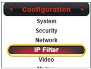
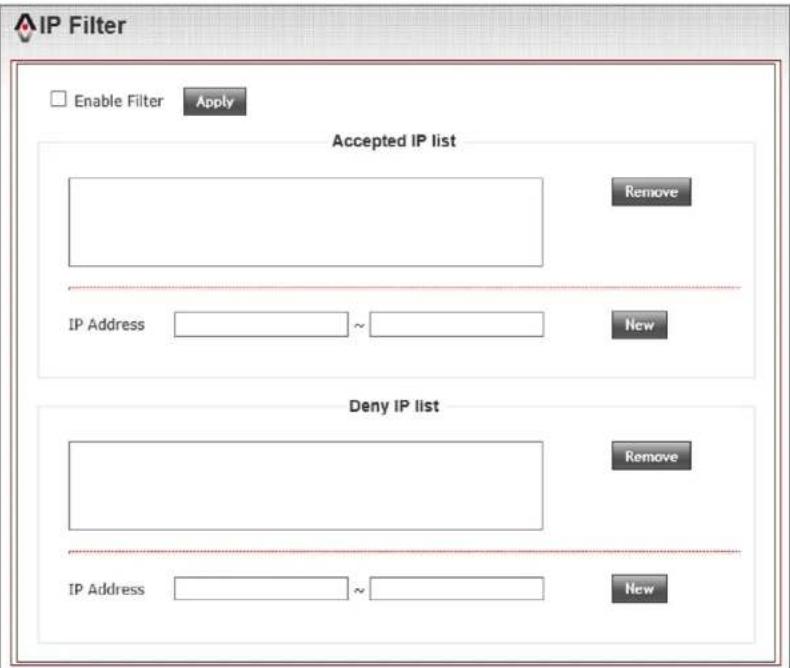
Comtrend network cameras have an "IP Filter" function. It can manage to set a white list for "Accepted IP list" or black list for "Deny IP list". It is recommended to use one rule only to keep the connection performance. The white list rule is the most common method used in a surveillance project.
IP Filter Setting Procedure :
Step 1.
Select "IP Filter" button under the "Configuration" menu. Step 2.
Select "Enable IP Filter".
Step 3.
Enter the IP List under "Accepted IP list" column, then press "New" button to add into white list.
Step 4.
Press "Apply" to save settings.
Notification :
Setting black list for Deny IP list is same process as for Accepted IP List described above.
COMTREND
www.comtrend.com
Chapter 5.
Configuration
5.3. Video & Audio Setting
This chapter includes all video setting, image adjusting, and audio setting.
5.3.1. Video Setting
5.3.1.1.Main Stream Setting
Main Stream Setting Procedure :
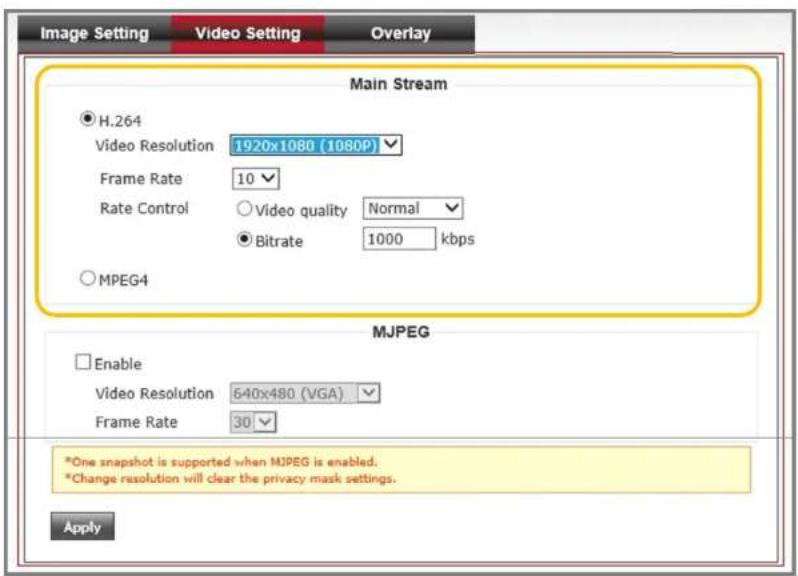
Step 1.
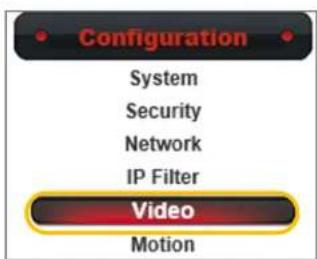
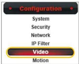
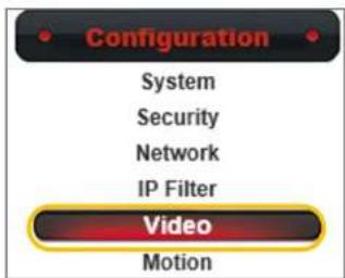
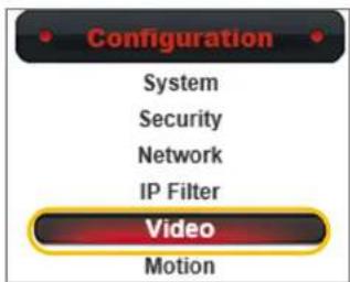
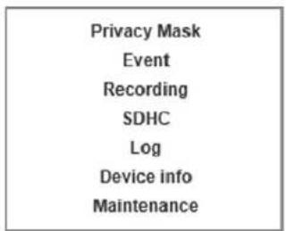
Select the "Video" button under the "Configuration" menu.
Step 2.
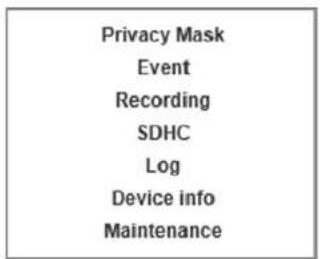
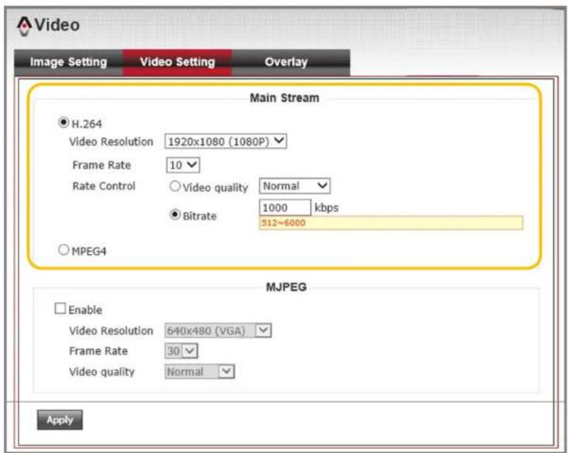
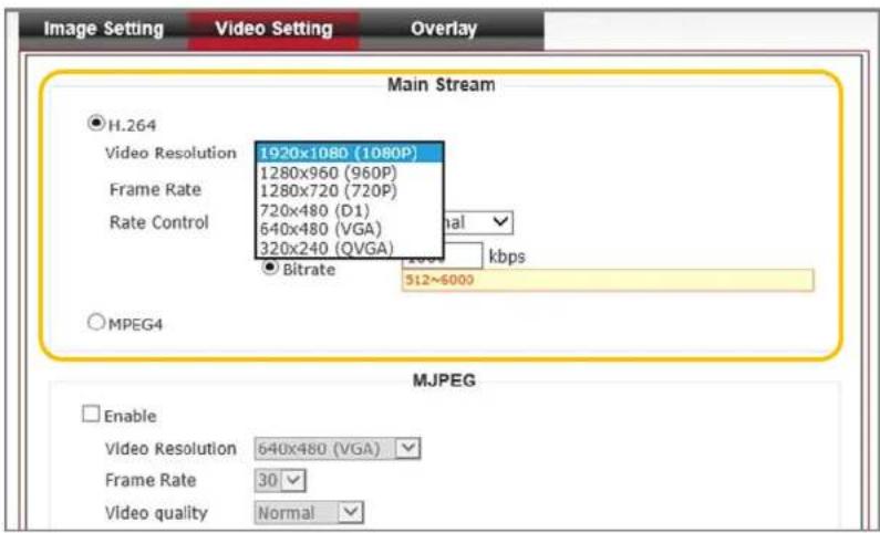
Select your desired format under the Main Stream column. Default is set as H.264 format. It can be changed to MPEG-4 format.
Step 3.
Define your Resolution, Frame Rate(fps). Default is set as 1920x1080 (1080P) @ 30fps.
Step 4.
Define your Rate control type. You can choose between Video quality or Bitrate comes first. Default is set as a constant Bitrate of 5000kbps. Press "Apply" to save settings.
COMTREND
www.comtrend.com
Chapter 5.
Configuration
5.3.1.1. Main Stream Setting
Rate Control Setting Description:
For a network camera only environment, we suggest setting the Video quality to Normal. If your surveillance environment is equipped with an NVR or NAS server for recording purposes, we suggest to set a constant Bitrate numbers.
Below is a suggestion chart for the video quality setting depending on your environment.
Notification :
When changing resolution settings will erase your privacy mask setting.
Resolution Fps Bitrate suggestion
| 1920 x 1080304000~6000 kbps | ||
| 1920 x 1080152000~3000 kbps | ||
| 1920 x 1080101000~2000 kbps | ||
| 1280 x 960302000~3500 kbps | ||
| 1280 x 960151000~2500 kbps | ||
| 1280 x 720 | 15 | 800~2300 kbps |
| 720 x 480 | 15 | 768~1500 kbps |
| 640 x 480 | 15 | 512~1200 kbps |
| 320 x 480 | 15 | 256~900 kbps |
Chapter 5.
Configuration
5.3.1.1. Main Stream Setting
Main Stream and Storage Calculation:
It is best to set a constant Bitrate number to make calculating recording storage space easier.
Calculate the storage space as described below for each network camera recording for one hour.
Bitrate(kbps) / 8 x 60(sec.) x 60(min.) / 1000 / 1000 = The storage space for each hour(GB)
Example Question :
If a camera is set at 1920x1080 (1080P)@ 10fps, 1000kbps as a Bitrate setting, how much space does a storage device need to hold at least a month (30days) of recording files?
Answer :
1000(kbps) / 8 x 60 x 60 / 1000 / 1000 x 24(hrs) x 30(days) = 324(GB) / 1000 = 0.324(TB)
Chapter 5.
Configuration
5.3.1.2. Secondary Stream(MJPEG) Setting
Secondary Stream(MJPEG) Setting Procedure :
Step 1.
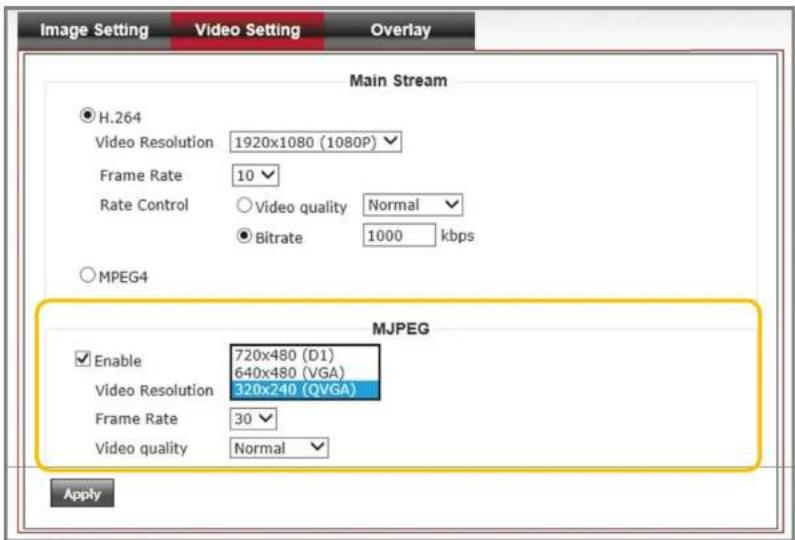
Select "Video" button under the "Configuration" menu. Then goes to "Video Setting" page and select "Enable" under "MJPEG" column.
Step 2.
Define your "Video Resolution". There are three resolutions to choose from 720x480(Full D1), 640x480(VGA) and 320x240(QVGA).
Step 3.
Define your "Frame Rate" and "Video Quality". There are five segment of video quality from lowest to highest that you can choose from. Then press "Apply" to save setting.
Notification :
MJPEG compression rate is lower than H.264 and MPEG-4. But is best format for computer CPU performance when handling the image. The snapshot function only supports MJPEG format.
| Resolution Fps Bitrate suggestion | |
| 720 x 4805Normal | (1000~2000 kbps) |
| 640 x 4805Normal | (800~1800 kbps) |
| 320 x 4805Normal | (200~600 kbps) |
COMTREND
www.comtrend.com
Chapter 5.
Configuration
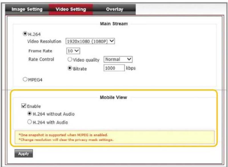
5.3.1.3. Mobile View Setting
Mobile View Setting Procedure :
Step 1.
Select the "Video" button under the "Configuration" menu. Select "Enable" under "Mobile View" column.
Step 2.
Select with or without audio depends on your application.
Step 3.
Press "Apply" to save changes.
Notification :
Mobile stream format is set to H.264 for a better compression rate. Default resolution is set as 320x240, 30fps. But the actual transfer speed is depends on your regional environment. Actual performance will vary depending on network performance factors.
| Resolution fps Bitrate suggestion | ||
| 320 x 240 | Max. 30 | Normal(500~1000 kbps) |
COMTREND
www.comtrend.com
Chapter 5.
Configuration
5.3.2. Focus Setting
Comtrend MD-21 network cameras are equip with f=3.6mm fixed Lens. In order to adjust the focus point, you will need to remove the top cover.
Focus Setting Procedure :
Step 1.
Please remove the top cover.
Step 2.
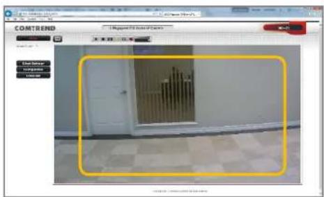
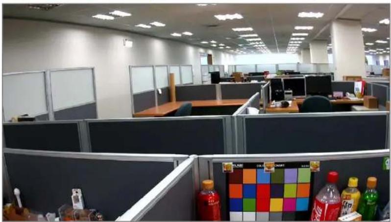
Set your browser to the main page and double click on the screen to the full screen mode.
Step 3.
Adjust the focus to get your desire clean view of your target by gently rotate the lens. Then put your top cover back on without touching the lens.
natural_image
Interior view of a busy office cubicle with desks, chairs, and colorful bottles on the floor (no visible text or signage)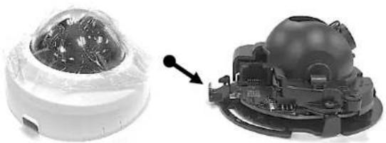
natural_image
Two views of a smart home control device: one with a dome and sensor, the other with a mechanical component (no visible text or symbols)COMTREND
www.comtrend.com
Chapter 5.
Configuration
5.3.3. Image Setting
After completing your video setting, follow the instructions below to adjust your image settings.
5.3.3.1. Exposure Setting
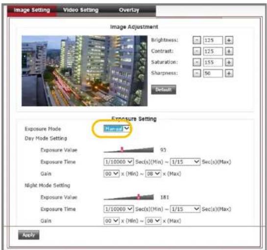
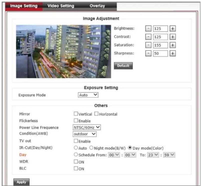
Comtrend network cameras provide two Exposure Modes. Default setting as "Auto" mode. You can change to "Manual" mode for advanced exposure settings for day and night modes.
COMTREND
www.comtrend.com
Chapter 5.
Configuration
5.3.3.1. Exposure Setting
Exposure Setting Procedure :
Step 1.
Select the "Video" button under the "Configuration" menu. Then go to "Image setting" and change the "Exposure Mode" from "Auto" to "Manual".
Step 2.
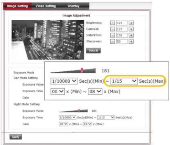
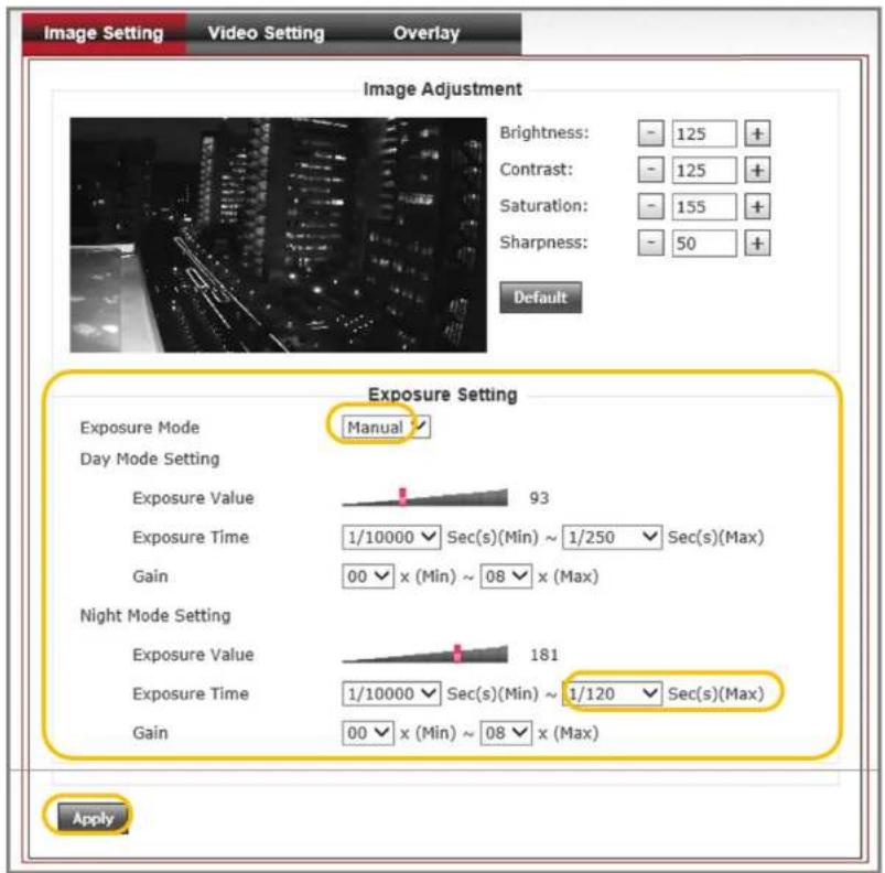
As an example, the picture to the right has an image that is too dark during night mode operations. We can manually adjust the maximum Exposure Time to 1/15 Seconds to improve the night time image.
Step 3.
Press the "Apply" button to save settings and get a better image quality as shown below.
COMTREND
www.comtrend.com
Chapter 5.
Configuration
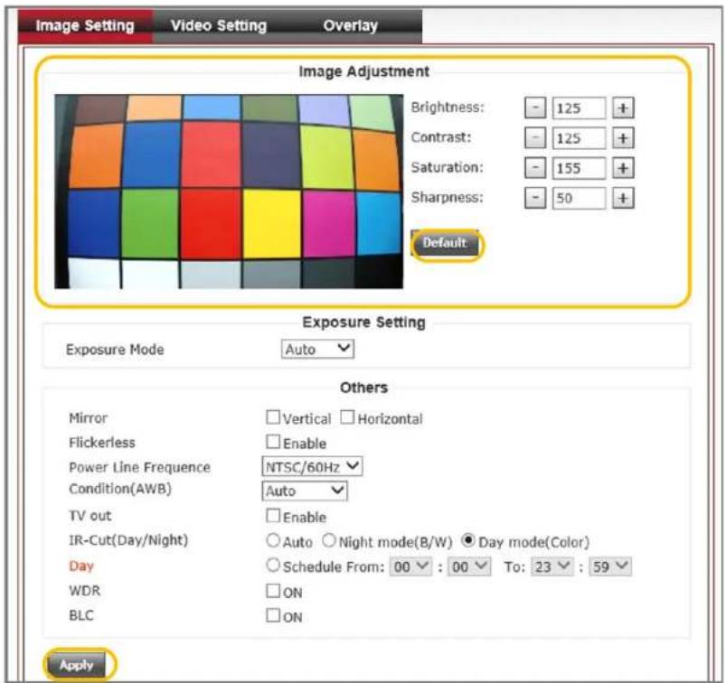
5.3.3.2. Image Setting
Image Setting Procedure :
Step 1.
Select the "Video" button under the "Configuration" menu. Then go to the "Image setting" tab.
Step 2.
Enter the desired Brightness, Contrast, Saturation and Sharpness numbers. Or use + and - button to do the adjusting incrementally.
Step 3.
Verify your changes with the image. Once you have gotten your ideal results, press the "Apply" button to save your settings.
Notification :
The range of Brightness, Contrast, Saturation and Sharpness numbers are from 0 to 255. Press the "Default" button if you wish to go back to the original factory settings. Press the "Apply" button to save your settings.
Chapter 5.
Configuration
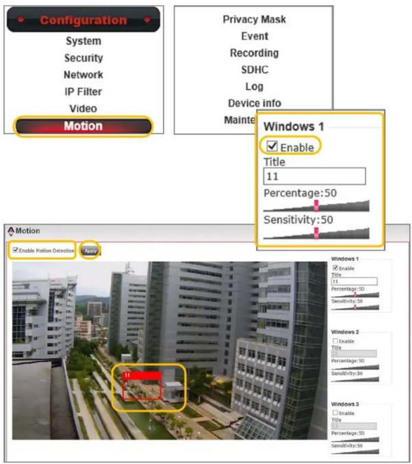
5.3.2. Motion Detection
The Motion Detection function allows you to set up to three motion detection windows on the screen. So these selected areas can detect motion base on the Percentage and Sensitivity numbers that are set.
Motion Detection Setting Procedure :
Step 1.
Select the "Motion Detection" button under the "Configuration" menu.
Step 2.
Select "Enable Privacy Mask", then select "Enable" under the "Windows 1" column and define a "Title" to this windows.
Step 3.
Resize the "Windows 1" frame and drag it to the area on the screen that you wish to monitor for motion.
Step 4.
Adjust the "Percentage" and "Sensitivity" settings to optimize your motion detection triggers.
Step 5.
Press the "Apply" button to save your settings.
Chapter 5.
Configuration
5.3.3. Privacy Mask
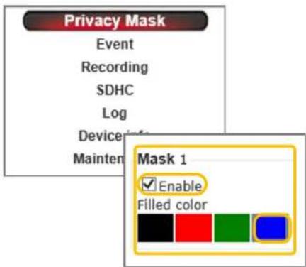
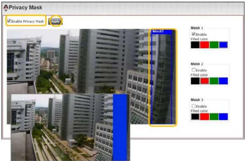
The "Privacy Mask" function allows you to set up to three privacy masks that cover on your live view screen. The color of the mask can be selected from one of the four available colors. Once the mask has been set, the live view screen will no longer display the masked area.
Privacy Mask Setting Procedure :
Step 1.
Select the "Privacy Mask" button under the "Configuration" menu.
Step 2.
Select the "Enable Privacy Mask", then select "Enable" under "Mask 1" column.
Step 3.
Resize the "Mask 1" frame and drag it to the place on the screen that you wish to cover.
Step 4.
Select the "Filled Color".
Step 5.
Press the "Apply" button to save "Mask 1" settings. If wish to set up "Mask 2" and "Mask 3", repeat the above procedure.
COMTREND
www.comtrend.com
Chapter 5.
Configuration
5.3.5. Audio Settings
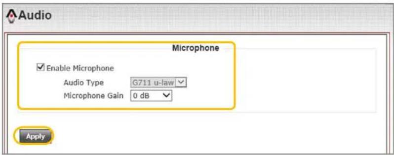
Comtrend MD-21 network cameras are equipped with an internal microphone. You may enable the microphone function within the web UI.
One ways audio setting procedure :
Step 1.
Select the "Audio" button under the "Configuration" menu.
Step 2.
Select "Enable Microphone". Select the "Audio Type" and set the "Microphone Gain".
Step 3.
Press the "Apply" button to save the setting.
Notification :
Available audio features vary by camera models. Some models have a built-in microphone, speaker outputs or both.
Chapter 5.
Configuration
5.4. SD Card Settings
The Comtrend MD-21 Camera has a built-in micro SD card slot for on camera recording. Micro SDHC cards up to 32GBs in capacity are supported.
5.4.1. SDHC
Setting new SD card procedure :
Step 1.
Select the "SDHC" button under the "Configuration" menu.
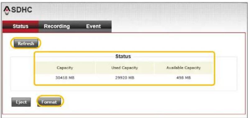
Step 2.
Select the "Status" page. If no SD card information is displayed, check that the SD card is properly inserted. Press the "Refresh" button to see SD card information.
Step 3.
When using an SD card for the first time, it is necessary to format the card. Press the "Format" button to start the format process. Once complete, your SD card will be ready for use.
Chapter 5.
Configuration
5.4.2. Recording
Recording to SD card procedure :
Step 1.
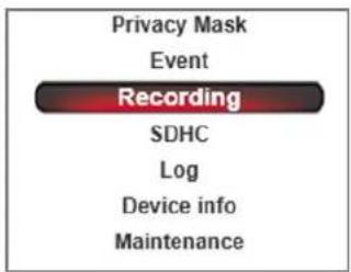
Select the "Recording" button under the "Configuration" menu.
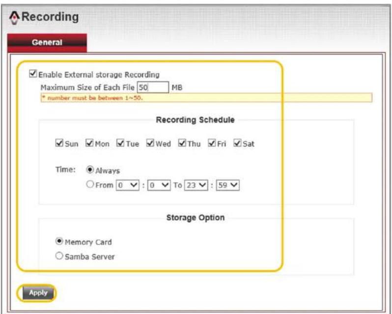
Step 2.
Select "Enable External storage Recording" function and set the maximum size of each recording file. The maximum file size must be set between 1MB and 50MBs in size.
Step 3.
Set your recording schedule in the "Recording Schedule" section.
Step 4.
Select "Memory card" under the "Storage Option" section. Then press the "Apply" button to save setting.
Notification :
Under the "Storage Option" section, You can also choose to save your recoding files to a Samba Server. For the limitation of each recording file size is from 1\~50MB. Each recording file length will depend on the setting of your recording stream.
COMTREND
www.comtrend.com
Chapter 5.
Configuration
5.4.3. SD Card Recoding Search
SD card recoding search procedure :
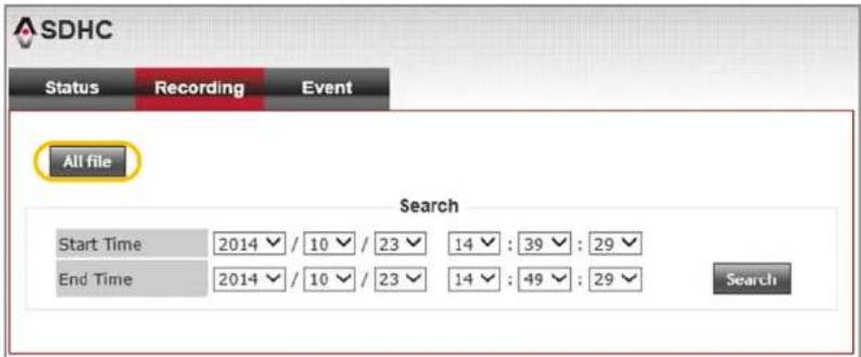
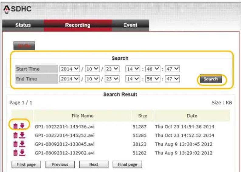
Step 1.
Select the "Recording" button under the "SDHC" page.
Step 2.
Press the "All file" button to see all recording files from the SD memory card. You can search a specific period of recording by setting a desired Start Time and End Time. Then press the "Search" button to sort the recording files within the specified period.
Step 3.
You can choose to download the recording files to your computer or to delete file from memory card.
Chapter 5.
Configuration
5.4.3. SD Card Event Recoding Search
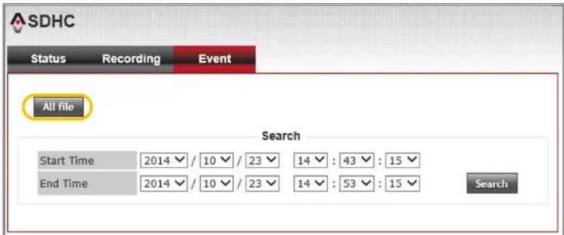
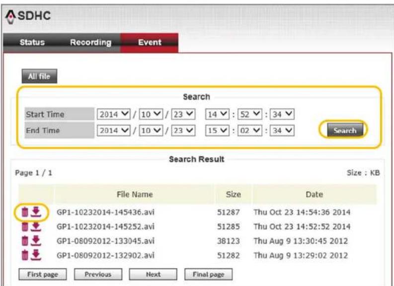
When event recording is triggered and saves to SD memory card, You can search all event files within the "Event" page.
SD card event recoding search procedure :
Step 1.
Select the "Event" button under the "SDHC" page.
Step 2.
Press the "All file" button to see all event recording files on the SD memory card. You can search a specific period of recording by setting a desired Start Time and End Time. Then press the "Search" button to sort the recording files within the specified period.
Step 3.
You can choose to download the recording files to your computer or to delete file from memory card.
Chapter 5.
Configuration
5.5. Event Settings
The Event Setting page allows you to define event triggers to cause the camera to perform an action. You can set multiple event based on your application.
Comtrend network cameras have two event triggers and 5 possible actions:
1) Motion Detection 2) Digital Input signal
Actions includes :
1) Send to FTP
2) Send to Email
3) Record to Samba
4) Record to SD Card
5) Trigger Digital Output
COMTREND
www.comtrend.com
Chapter 5.
Configuration
5.5.1. Event Server
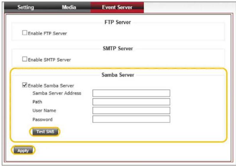
The "Event Server" tab is used to setup the media server that will support the "Action" from a "Triggered Event". FTP, SMTP and Samba are the three media server types that are supported.
5.5.1.1. FTP Server
FTP Server setting procedure :
Step 1.
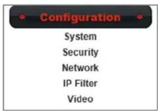
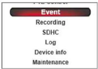
Select the "Event" button under the "Configuration" menu. Then select "Event server" tab.
Step 2.
Select "Enable FTP server". Enter your FTP server's IP address, Port, Username, Password and File path Name. You may select "Enable Passive Mode" depending on your FTP server configuration.
Notification :
Default FTP Port is set to 21.
Step 3.
Press the "Test FTP" button to check if the FTP connection was successfully established.
Step 4.
Press the "Apply" button to save settings.

COMTREND
www.comtrend.com
Chapter 5.
Configuration
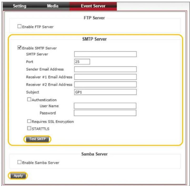
5.5.1.2. SMTP Server
The main function of the SMTP server it to send an e-mail message when an event is triggered.
SMTP Server setting procedure :
Step 1.
Select the "Event" button under the "Configuration" menu. Then select the "Event Server" tab.
Step 2.
Select the "Enable SMTP server". Enter your SMTP server's IP address, Port, Sender e-mail address, Receiver #1 and #2 e-mail address and Subject. Indicate whether there is authentication required. Provide a Username and Password if necessary. You may select Require SSL Encryption and StartTLS if necessary for your server.
Notification :
Default SMTP Port is set to 25.
Step 3.
Press the "Test SMTP" button to check if the SMTP connection was successfully established.
Step 4.
Press the "Apply" button to save setting.
Chapter 5.
Configuration
5.5.1.3. Samba Server
Samba Server setting procedure :
Step 1.
Select the "Event" button under the "Configuration" menu. Then select the "Event Server" tab.
Step 2.
Select "Enable Samba Server". Enter your Samba server's IP address, Storage Path, Username and Password.
Step 3.
Press the "Test Samba" button to check if the Samba connection was successfully established.
Step 4.
Press the "Apply" button to save setting.
Chapter 5.
Configuration
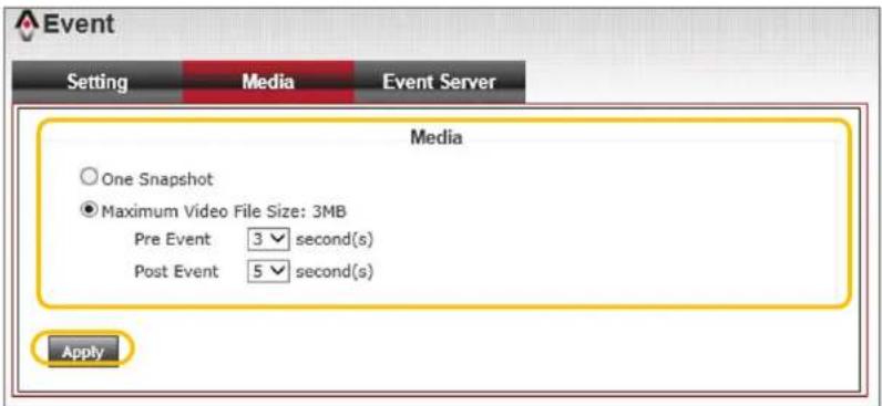
5.5.2. Media setting
Media settings are to define what kind of media files should be save when an event is triggered. You can send a snapshot or an event recording file to your event server.
Media setting procedure :
Step 1.
Select the "Event" button under the "Configuration" menu. Then select the "Media" tab.
Step 2.
Select the "Snapshot" or "Maximum Video File Size". You can set the pre and post event time when selecting video as the media format. The length of "Pre Event" and "Post Event" are both configurable from 1 to 5 seconds.
Notification :
The maximum event recording file size is 3MB. Recommended "Pre Event" as 2 seconds and "Post Event" as 3 seconds.
Step 3.
Press the "Apply" button to save setting.
Chapter 5.
Configuration
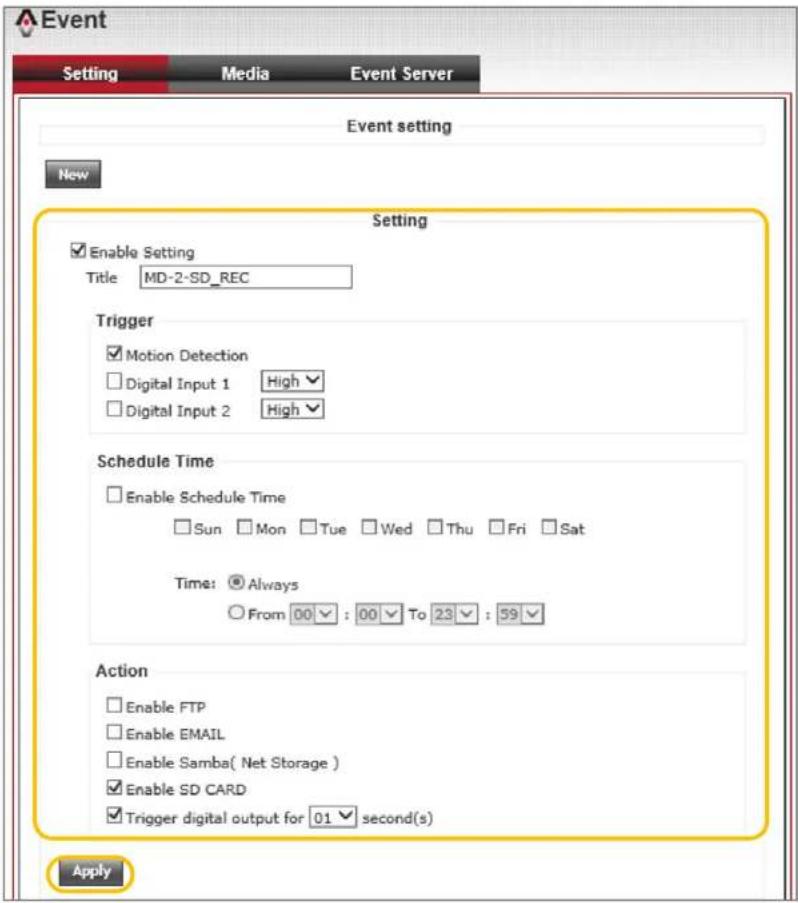
5.5.3. Adding New Event Settings
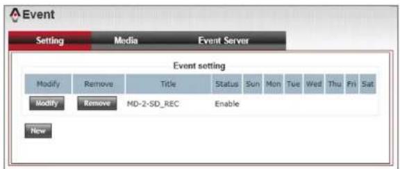
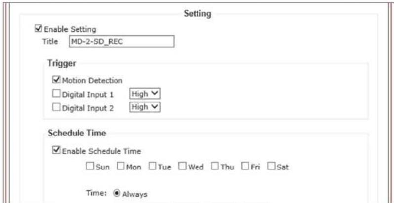
Event Settings will allow you to configure events that are triggered by either "Motion Detection" or "Digital Input". You can establish a "Schedule Time" for when the event will be active. Five "Action" types are available for each triggered "Event".
Example of adding new event procedure:
Step 1.
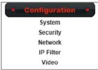
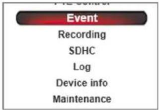
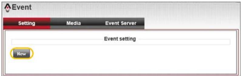
Select the "Event" button under the "Configuration menu". Then select the "New" button to open the "Settings" page.
Step 2.
Select "Enable Setting" and provide the "Event" title.
Step 3.
Select "Motion Detection" as a trigger.
Step 4.
Select "Enable Schedule Time" and select all days from Sunday to Saturday. Then set the time as Always.
Step 5.
Select "Enable SD Card" and "Enable Digital Output" as your action. Also set your digital output time as 10 seconds.
Step 6.
Press the "Apply" button to save setting.
COMTREND
www.comtrend.com
Chapter 5.
Configuration
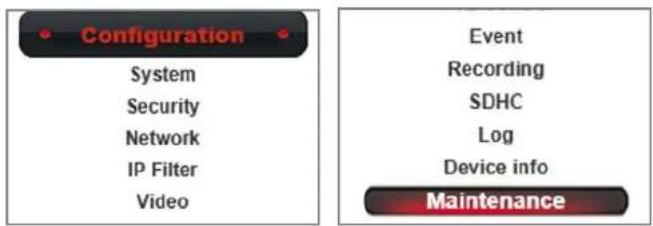
5.6. Maintenance Settings
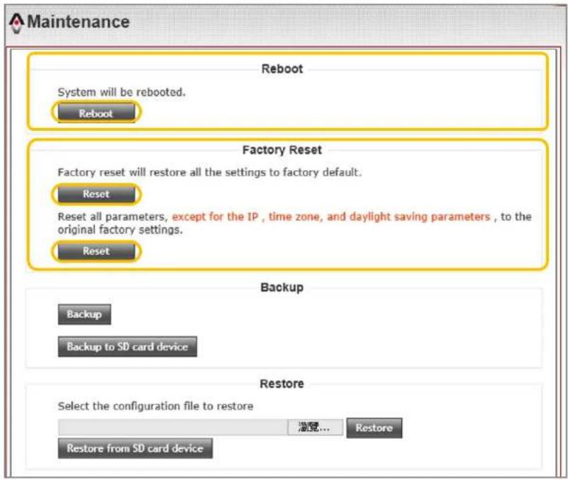
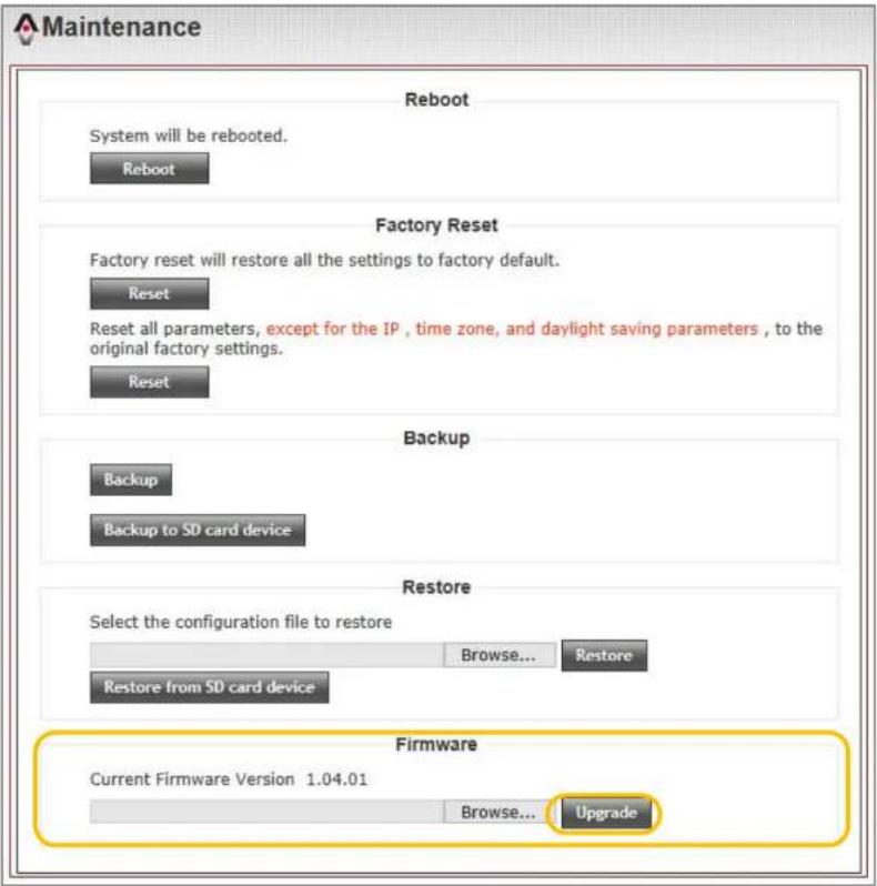
This maintenance page includes Reboot, Factory Reset, Backup, Restore, and Upgrade functions.
5.6.1. Reboot
Reboot procedure:
The "Reboot" feature is used to remotely reboot the camera.
5.6.2. Factory reset
There are two "Factory Reset" options. The first option will reset all camera parameters to factory default. The second option will reset all parameters, except for the IP address, time zone and daylight savings parameters.
Reboot and Reset procedures:
To "Reboot" or "Reset" t h camera, press the "Reboot" or "Reset" buttons.
Chapter 5.
Configuration
5.6.3. Backup
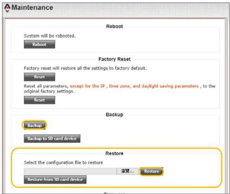
Comtrend cameras can back-up your camera settings to either local computer or on to an installed SD card.
Backup procedure:
When you press the "Backup" button, the Comtrend camera will back-up it's setting to your computer. When you press the "Backup to SD card device" button, the Comtrend camera will back-up it's settings to the installed SD card.
5.6.4. Restore
Comtrend cameras can restore back-up files from the procedure above.
Restore procedure:
When restoring files from your computer, press the "Browse" but target select the backup file that you saved. Then press the "Restore" button. When restoring settings from the SD card, press "Restore from SD card device" button.
COMTREND
www.comtrend.com
Chapter 5.
Configuration
5.6.5. Upgrade
Comtrend cameras contain its original firmware version when they first leave the factory. Comtrend will have the latest firmware version on the Comtrend website.
Firmware upgrade procedure:
Download the latest firmware version to your computer. Click the "Browse" button and select the firmware you want to upload to the camera. Click the "Upgrade" button to begin the upgrade. Once the upgrade is complete, "Reboot" your camera.
Chapter 5.
Configuration
5.7. Camera Information
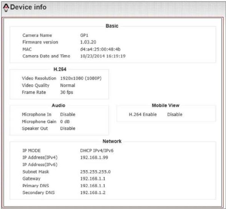
Comtrend network cameras provide two ways of checking information. One is form the device information, it includes the fundamental of network setting and basic function of the camera. The other one is in the system log, it records all the operation and event history.
5.7.1. Device information
Device info display procedure:
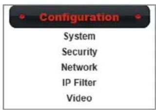
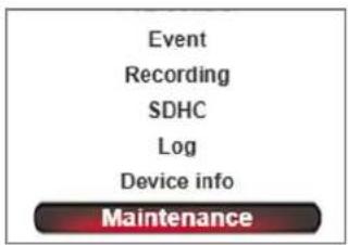
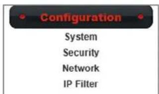
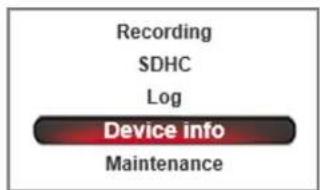
To access device info, click "Configuration" from the menu then click the "Device Info" button.
Chapter 5.
Configuration
5.7.2. System Log
System log display procedure:
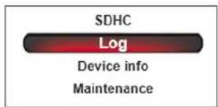
To access system log, click "Configuration" from the menu then click the "Log" button.
![System Log Item Date and Time Event 1. 10/23/2014 16:16:57 admin login on 192.168.1.11 2. 10/23/2014 15:46:55 [EVENT MGR]:Reload Config File 3. 10/23/2014 15:26:57 admin login on 192.168.1.11 4. 10/23/2014 15:18:17 [EVENT MGR]: reload config file 5. 10/23/2014 15:02:41 [SDCard]: List Fail !!! 6. 10/23/2014 14:52:52 [Recording]:SDCard Space=31058128 KB is enough 7. 10/23/2014 14:52:52 [Recording]:Recording Start 8. 10/23/2014 14:52:45 admin login on 192.168.1.11 9. 08/09/2012 13:32:02 [Recording]:Recording Stop 10. 08/09/2012 13:29:18 [SDCard]: List Fail !!! 11. 08/09/2012 13:29:02 [Recording]:SDCard Space=31147552 KB is enough 12. 08/09/2012 13:29:00 [Recording]:Recording Start 13. 08/09/2012 13:12:25 [SDCard]: Format Success !!! 14. 08/09/2012 13:07:32 admin login on 192.168.1.11 15. 08/09/2012 13:03:57 [NET]:UPnPAV Disable 16. 08/09/2012 13:03:13 [RTSP SERVER]:Start one session<192.168.1.99> 17. 08/09/2012 13:03:07 [NET]:UPnPAV Disable 18. 08/06/2012 15:44:01 [NET]:UPnPAV Disable 19. 08/06/2012 15:43:18 [RTSP SERVER]:Start one session<192.168.1.99> 20. 08/06/2012 15:43:11 [NET]:UPnPAV Disable First page Previous Next Final page Remove](/content/2026/05/1001684/images/08b06ffdea421410ec0ce1a415c9b890cfa36ad31b8c8b729b51b17d98bb669f.jpg)
COMTREND
www.comtrend.com
Chapter 5.
Configuration
COMTREND
www.comtrend.com
Chapter 6.
Appendix
6.1. Liability
Comtrend Corporation does not responsible for any printing errors or any related issues. And hereby to claim that all specification or description within this manual are subject to change without notice.
All statement of guarantee by Comtrend Corporation are listed within this manual. But it does not apply to any other particular purpose with those implied statement.

WEEE Directive & Product Disposal
At the end of its serviceable life, this product should not be treated as household or general waste. It should be handed over to the applicable collection point for the recycling of electrical and electronic equipment, or returned to the supplier for disposal.
Chapter 6.
Appendix
6.1. Copyright
Copyright Comtrend Corporation all rights reserved. No part of this publication may be reproduced, transmitted, transcribed, stored in a retrieval system, or translated into any language or computer language, in any form or by any means, electronic, mechanical, magnetic, optical, chemical, manual or otherwise, without the prior written permission from Comtrend Corporation.
Comtrend Corporation makes no representations or warranties, either expressed or implied, with respect to the contents hereof and specifically disclaims any warranties, merchantability, or fitness for any particular purpose. Any software described in this manual is sold or licensed as is. Should the programs prove defective following their purchase, the buyer (and not this company, its distributor, or its dealer) assumes the entire cost of all necessary servicing, repair, and any incidental or consequential damages resulting from any defect in the software. Comtrend Corporation reserves the right to revise this publication and to make changes from time to time in the contents hereof without the obligation to notify any person of such revision or changes.
The product you have purchased and the setup screen may appear slightly different from those shown in this QIG. For more information about this product, please refer to the user manual on the CD-ROM. The software and specifications are subject to change without notice. Please visit our website www.Comtrend.com for updates. All brand and product names mentioned in this manual are trademarks and/or registered trademarks of their respective holders.
Notice According to GNU General Public License Version 2
This product includes software that is subject to the GNU General Public License version 2. The program is free software and distributed without any warranty of the author. We offer, valid for at least three years, to give you, for a charge no more than the costs of physically performing source distribution, a complete machine-readable copy of the corresponding source code.
Version 2, June 1991
Copyright (C) 1989, 1991 Free Software Foundation, Inc. 51 Franklin Street, Fifth Floor, Boston, MA 02110-1301, USA
Everyone is permitted to copy and distribute verbatim copies of this license document, but changing it is not allowed.
COMTREND
www.comtrend.com
- User Manual
- CONTENTS
- Chapter I.
- Overview
- Chapter 2.
- Installation
- Chapter 3.
- Accessing
- Chapter 4.
- WEB UI
- Chapter 5.
- Configuration
- Chapter 6.
- Appendix
- Read Before Use
- Physical Description
- Mechanical and hardware interface
- Digital Input (DI)
- Safety Instructions
- Package Contents
- EMC (Electromagnetic Compatibility)
- FCC Statement
- CE Mark Warning
- Installation
- COMTREND
- Comtrend IPFinder Installation
- Comtrend Finder Installation :
- Comtrend Finder procedure :
- Step 1.
- Step 2.
- Notification:
- Ready to Use
- Access procedure:
- Step 3.
- Network Deployment
- Structure as shown on the right
- Notification :
- Network Environment Setting
- True IP address setting
- Transfer from UPnP router
- Step 4.
- PPPoE connection setting
- Comtrend Network Camera connection :
- Accessing via Web UI
- Accessing via RTSP Player
- Home page
- Client Settings
- Protocol options
- Storage Options
- Configuration Settings
- System
- System
- Security
- Administrator Setting Procedure :
- Network Settings
- General Network Settings
- General Network Settings Recommendation
- Intranet Static IPv4/IPv6 Setting Static IPv4 Setting Procedure :
- Internet Static IPv4/IPv6 Setting Static IPv4 Setting Procedure :
- PPPoE Setting
- Advanced Network Setting
- HTTPS Settings
- DDNS Settings
- DDNS Settings Procedure :
- Multicast Setting
- Multicast Description :
- Multicast Setting Procedure :
- QoS Setting
- QoS Setting Procedure :
- Bonjour Setting
- IP Filter
- IP Filter Setting Procedure :
- Video & Audio Setting
- Video Setting
- 5.3.1.1.Main Stream Setting
- Main Stream Setting
- Secondary Stream(MJPEG) Setting
- Mobile View Setting
- Focus Setting
- Focus Setting Procedure :
- Image Setting
- Exposure Setting
- Exposure Setting Procedure :
- Image Setting
- Image Setting Procedure :
- Motion Detection
- Motion Detection Setting Procedure :
- Step 5.
- Privacy Mask
- Privacy Mask Setting Procedure :
- Audio Settings
- One ways audio setting procedure :
- SD Card Settings
- SDHC
- Setting new SD card procedure :
- Recording
- SD Card Recoding Search
- SD Card Event Recoding Search
- SD card event recoding search procedure :
- Event Settings
- Event Server
- FTP Server
- SMTP Server
- SMTP Server setting procedure :
- Samba Server
- Media setting
- Media setting procedure :
- Adding New Event Settings
- Example of adding new event procedure:
- Step 6.
- Maintenance Settings
- Reboot
- Reboot procedure:
- Factory reset
- Reboot and Reset procedures:
- Backup
- Backup procedure:
- Restore
- Restore procedure:
- Upgrade
- Firmware upgrade procedure:
- Camera Information
- Device information
- Device info display procedure:
- System Log
- Liability
- WEEE Directive & Product Disposal
- Copyright
- Notice According to GNU General Public License Version 2
Brand : Comtrend
Model : VD-21IRVF
Category : Security Camera