
INSTALLATION - Home Appliance WHIRLPOOL - Free user manual and instructions
Find the device manual for free INSTALLATION WHIRLPOOL in PDF.

| Product Type | Built-in oven |
| Brand | Whirlpool |
| Model | INSTALLATION |
| Overall dimensions (single 27") | Width: 67.9 cm, Height: 73.7 cm, Depth: 58.4 cm |
| Overall dimensions (single 30") | Width: 75.6 cm, Height: 73.7 cm, Depth: 58.4 cm |
| Built-in dimensions (single 27") | Width: 64.8 cm, Height: 70.5 cm, Depth: 59.1 cm |
| Built-in dimensions (single 30") | Width: 72.4 cm, Height: 70.5 cm, Depth: 59.1 cm |
| Weight (single oven) | 70 kg |
| Weight (double oven) | 130 kg |
| Power supply | 240 V / 208 V, 60 Hz, dedicated 30 A or 40 A circuit depending on model |
| Connection type | 3- or 4-conductor cable, with ground conductor |
| Front material | Stainless steel |
| Main functions | Custom Broil, custom cooking |
| Safety | Safety alert, door hinge lock |
| Installation | Built into a cabinet, requires level and specific tools |
| Required clearance | Minimum 1" (2.5 cm) between top of oven and upper cabinet |
| Maximum cabinet temperature | 194°F (90°C) |
| Standards | UL and CSA |
| Maintenance | Cleaning according to use and care guide |
| Supplied parts | Mounting screws, side trims, bottom vent (depending on model) |
| Required tools | Phillips screwdriver, tape measure, drill, level |
| Reparability | Call a qualified electrician or authorized technician |
Frequently Asked Questions - INSTALLATION WHIRLPOOL
User questions about INSTALLATION WHIRLPOOL
0 question about this device. Answer the ones you know or ask your own.
Ask a new question about this device
Download the instructions for your Home Appliance in PDF format for free! Find your manual INSTALLATION - WHIRLPOOL and take your electronic device back in hand. On this page are published all the documents necessary for the use of your device. INSTALLATION by WHIRLPOOL.
USER MANUAL INSTALLATION WHIRLPOOL
INSTALLATION INSTRUCTIONS
27" (68.6 CM) AND 30" (76.2 CM) ELECTRIC SINGLE
AND DOUBLE BUILT-IN OVEN
INSTRUCTIONS D'INSTALLATION
FOUR ÉLECTRIQUE ENCASTRÉ DE 27" (68,6 CM) ET 30"
(76,2 CM) - SIMPLE ET DOUBLE
Table of Contents/Table des matieres
BUILT-IN OVEN SAFETY 2
INSTALLATION REQUIREMENTS 2
Tools and Parts 2
Location Requirements 2
Electrical Requirements 4
INSTALLATION INSTRUCTIONS 5
Prepare Built-In Oven 5
Remove Oven Door 5
Remove Oven Trim 5
Make Electrical Connection. 5
Install Oven 7
Complete Installation 8
SECURITE DU FOUR ENCASTRE 9
EXIGENCES D'INSTALLATION 9
BUILT-IN OVEN SAFETY
Your safety and the safety of others are very important.
We have provided many important safety messages in this manual and on your appliance. Always read and obey all safety messages.

This is the safety alert symbol.
This symbol alerts you to potential hazards that can kill or hurt you and others.
All safety messages will follow the safety alert symbol and either the word "DANGER" or "WARNING."
These words mean:
DANGER
WARNING
You can be killed or seriously injured if you don't immediately follow instructions.
All safety messages will tell you what the potential hazard is, tell you how to reduce the chance of injury, and tell you what can happen if the instructions are not followed.
INSTALLATION REQUIREMENTS
Tools and Parts
Gather the required tools and parts before starting installation. Read and follow the instructions provided with any tools listed here.
Tools needed
Phillips screwdriver
Measuring tape
Hand or electric drill (for wall cabinet installations)
1" (25 mm) drill bit (for wall cabinet installations)
Level
Parts needed
UL listed or CSA approved conduit connector
UL listed wire connectors
Parts supplied
8-14 x 1" screws - single oven (2), double oven (4)
Bottom vent (supplied on some models)
Two # 8-18 x 3 % screws - bottom vent
Side trim
Check local codes. Check existing electrical supply. See "Electrical Requirements."
It is recommended that all electrical connections be made by a licensed, qualified electrical installer.
Location Requirements
IMPORTANT: Observe all governing codes and ordinances.
Cabinet opening dimensions that are shown must be used. Given dimensions provide minimum clearance with oven.
- Recessed installation area must provide complete enclosure around the recessed portion of the oven.
Grounded electrical supply is required. See "Electrical Requirements" section.
- Electrical supply junction box should be located 3'' (7.6 cm) maximum below the support surface when the oven is installed in a wall cabinet. A 1'' (2.5 cm) minimum diameter hole should have been drilled in the right rear or left rear corner of the support surface to pass the appliance cable through to the junction box.
NOTE: For undercover installation, it is recommended that the junction box be located in the adjacent right or left cabinet. If you are installing the junction box on rear wall behind oven, the junction box must be recessed and located in the upper or lower right or left corner of the cabinet; otherwise, the oven will not fit into the cabinet opening.
- Oven support surface must be solid, level and flush with bottom of cabinet cutout. Floor must be able to support a single oven weight of 154 lbs (70 kg) or a double oven weight of 287 lbs (130 kg).
IMPORTANT: To avoid damage to your cabinets, check with your builder or cabinet supplier to make sure that the materials used will not discolor, delaminate or sustain other damage. This oven has been designed in accordance with the requirements of UL and CSA International and complies with the maximum allowable wood cabinet temperatures of 194^ (90^)
Undercounter Installation (with cooktop installed above): Ovens approved for this type of installation have an approval label located on the top of the oven. Refer to undercover installation instructions for cutout dimensions and approved oven cooktop combinations (separate sheet).
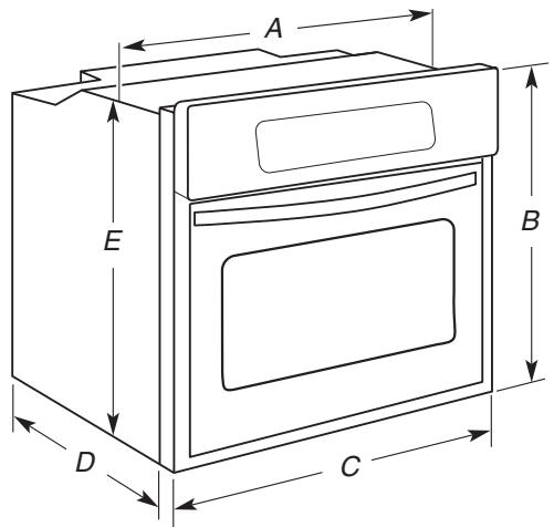
27'' (68.6 cm) models
A. 25^5 / 16 " (64.3 cm) max. recessed width
B. 29'' (73.7 cm) max. overall height
C. 2634 (67.9 cm) overall width
D. 23" (58.4 cm) max. recessed depth
E. 27 12 (69.9 cm) recessed height
30'' (76.2 cm) models
A. 28^5 / 16 " (71.9 cm) max. recessed width
B. 29'' (73.7 cm) max. overall height
C. 29^3 / 4 (75.6 cm) overall width
D. 23^ (58.4 cm) max. recessed depth
E. 27 12 (69.9 cm) recessed height
Cabinet Dimensions - Single Ovens
Single Oven Undercounter (without cooktop installed above)
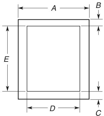
27^ (68.6 cm) models
A. 27'' (68.6 cm) min. cabinet width
B. 1 12 n (3.8 cm) min. top of cutout to underside of countertop
C. 51 / 4" (13.3 cm) bottom of cutout to floor
D. 25 12'' (64.8 cm) cutout width
E. 27^3/4 (70.5 cm) min. cutout height
30^ (76.2 cm) models
A. 30'' (76.2 cm) min. cabinet width
B. 112'' (3.8 cm) min. top of cutout to underside of countertop
C. 5 14'' (13.3 cm) bottom of cutout to floor
D. 28 12'' (72.4 cm) cutout width
E. 2734 (70.5 cm) min. cutout height
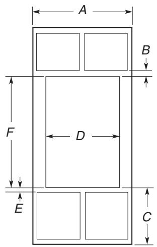
Single Ovens Installed in Cabinet
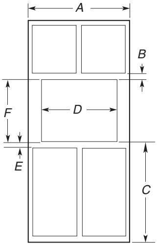
27" (68.6 cm) models
A. 27'' (68.6 cm) min. cabinet width
B. 1'' (2.5 cm) top of cutout to bottom of upper cabinet door
C. 32'' (81.3 cm) bottom of cutout to floor
D. 25 12'' (64.8 cm) cutout width
E. 112 (3.8 cm) min. bottom of cutout to top of cabinet door
F. 27% (70.5 cm) cutout height
30^ (76.2 cm) models
A. 30'' (76.2 cm) min. cabinet width
B. 1'' (2.5 cm) top of cutout to bottom of upper cabinet door
C. 32'' (81.3 cm) bottom of cutout to floor
D. 28 12'' (72.4 cm) cutout width
E. 112 (3.8 cm) min. bottom of cutout to top of cabinet door
F. 27% (70.5 cm) cutout height
Product Dimensions - Double Ovens
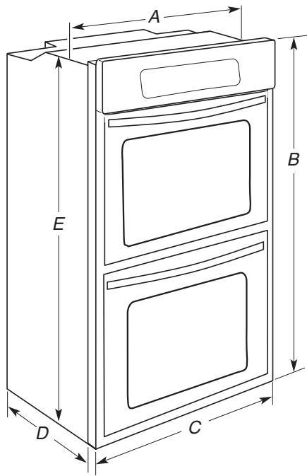
27'' (68.6 cm) models
A. 25 516'' (64.3 cm) max. recessed width
B. 51'' (129.5 cm) max. overall height
C. 26% (67.9 cm) overall width
D. 23'' (58.4 cm) max. recessed depth
E. 49 ‰ " (125.9 cm) recessed height
30^ (76.2 cm) models
A. 28^5 / 16 " (71.9 cm) max. recessed width
B. 51'' (129.5 cm) max. overall height
C. 29 34 (75.6 cm) overall width
D. 23'' (58.4 cm) max. recessed depth
E. 49 ‰ '' (125.9 cm) recessed height
Double Ovens Installed in Cabinet
27" (68.6 cm) models
A. 27'' (68.6 cm) min. cabinet width
B. 1'' (2.5 cm) top of cutout to bottom of upper cabinet door
C. 143 / 4'' (37.5 cm) bottom of cutout to floor
D. 25 12'' (64.8 cm) cutout width
E. 112 (3.8 cm) min. bottom of cutout to top of cabinet door
F. 493 / 4'' (126.4 cm) min. cutout height
30^ (76.2cm) models
A. 30'' (76.2 cm) min. cabinet width
B. 1'' (2.5 cm) top of cutout to bottom of upper cabinet door
C. 143 / 4'' (37.5 cm) bottom of cutout to floor
D. 28 12'' (72.4 cm) cutout width
E. 112 (3.8 cm) min. bottom of cutout to top of cabinet door
F. 493 / 4 " (126.4 cm) min. cutout height
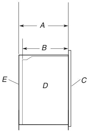
Cabinet Side View - Single or Double Oven
A. 23% (59.1 cm) min. cutout depth
B. 23^ (58.4 cm) recessed oven depth
C. Oven front
D. Recessed oven
E. Cabinet
Electrical Requirements
If codes permit and a separate ground wire is used, it is recommended that a qualified electrical installer determine that the ground path and the wire gauge are in accordance with local codes.
Check with a qualified electrical installer if you are not sure the oven is properly grounded.
This oven must be connected to a grounded metal, permanent wiring system.
Be sure that the electrical connection and wire size are adequate and in conformance with the National Electrical Code, ANSI/NFPA 70-latest edition or CSA Standards C22.1-94, Canadian Electrical Code, Part 1 and C22.2 No. O-M91-latest edition, and all local codes and ordinances.
A copy of the above code standards can be obtained from:
National Fire Protection Association
One Batterymarch Park
Quincy, MA 02269
CSA International
8501 East Pleasant Valley Road
Cleveland, OH 44131-5575
Electrical Connection
To properly install your oven, you must determine the type of electrical connection you will be using and follow the instructions provided for it here.
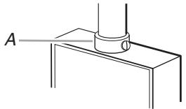
- Oven must be connected to the proper electrical voltage and frequency as specified on the model/serial number rating plate. The model/serial number rating plate is located at the bottom of the right-hand mounting rail. See the following illustrations.
Single Oven
A. Model/serial number plate
Double Oven
A. Model/serial number plate
- Models rated from 7.3 to 9.6kW at 240 volts (5.5 to 7.2kW at 208 volts) require a separate 40-amp circuit. Models rated at 7.2kW and below at 240 volts (5.4 kW and below at 208 volts) require a separate 30-amp circuit.
A circuit breaker is recommended. - Connect directly to the circuit breaker box (or fused disconnect) through flexible, armored or nonmetallic sheathed, copper cable (with grounding wire). See "Make Electrical Connection" section.
-
Flexible conduit from the oven should be connected directly to the junction box.
-
Do not cut the conduit. The length of conduit provided is for serviceability of the oven.
A UL listed or CSA approved conduit connector must be provided.
If the house has aluminum wiring, follow the procedure below: -
Connect a section of solid copper wire to the pigtail leads.
- Connect the aluminum wiring to the added section of copper wire using special connectors and/or tools designed and UL listed for joining copper to aluminum.
Follow the electrical connector manufacturer's recommended procedure. Aluminum/copper connection must conform with local codes and industry accepted wiring practices.
INSTALLATION INSTRUCTIONS
Prepare Built-In Oven
- Decide on the final location for the oven. Locate existing wiring to avoid drilling into or severing wiring during installation.
WARNING
Excessive Weight Hazard
Use two or more people to move and install oven.
Failure to do so can result in back or other injury.
- To avoid floor damage, set the oven onto cardboard prior to installation. Do not use handle or any portion of the front frame for lifting.
- Remove the shipping materials and tape from the oven.
- Remove the hardware package from inside the bag containing literature.
- Remove and set aside racks and other parts from inside the oven.
- Move oven and cardboard close to the oven's final location.
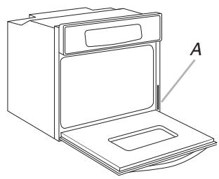
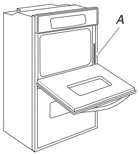
Remove Oven Door
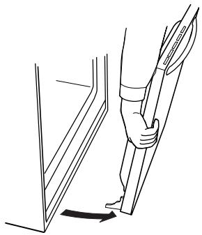
IMPORTANT: Use both hands to remove oven door(s).
- Open the oven door.
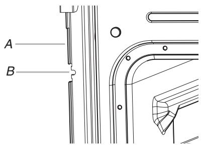
- Locate the oven door latches in both corners of the oven door, and rotate the latches forward to the unlocked position.
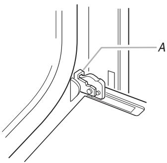
A. Oven door latch in locked position
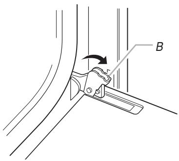
B. Oven door latch in unlocked position
- Grasp the edges of the oven door with both hands and close the oven door until it will no longer close. Lift and pull oven door toward you and remove. Set the oven door(s) aside on a covered work surface.
Remove Oven Trim
- Side trims are located on the right side of the oven. Cut the cable tie and remove side trims.
- Remove the cable tie from the side of the oven.
NOTE: Screws for attaching side trims (after oven is installed in cabinet) are in a screw bag inside the package containing literature.
Make Electrical Connection
WARNING

Electrical Shock Hazard
Disconnect power before servicing.
Use 8 gauge solid copper wire.
Electrically ground oven.
Failure to follow these instructions can result in death, fire, or electrical shock.
This oven is manufactured with a neutral (white) power supply wire and a cabinet-connected green (or bare) ground wire twisted together.
- Disconnect power.
-
Feed the flexible conduit from the oven through the opening in the cabinet.
-
Remove junction box cover, if it is present.
- Install a UL listed or CSA approved conduit connector to the junction box.
A. UL listed or CSA approved conduit connector
- Route the flexible conduit from the oven to the junction box through a UL listed or CSA approved conduit connector.
- Tighten screws on conduit connector.
- See "Electrical Connection Options Chart" to complete installation for your type of electrical connection.
Electrical Connection Options Chart
| If your home has: | Go to section: |
| 4-wire | 4-wire Cable from Home Power Supply |
| 3-wire | 3-wire Cable from Home Power Supply |
4-Wire Cable from Home Power Supply
IMPORTANT: Use the 4-wire cable from home power supply in the U.S. where local codes do not allow grounding through neutral, New Branch circuit installations (1996 NEC), mobile homes and recreational vehicles, new construction and in Canada.
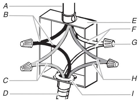
A. Cable from home power supply
B. Black wires
C. Red wires
D. 4-wire flexible conduit from oven
E. Junction box
F. White wires
G. UL listed wire connectors
H. Green (or bare) ground wires
I. UL listed or CSA approved conduit connector
- Connect the 2 black wires (B) together using a UL listed wire connector.
- Connect the 2 red wires (C) together using a UL listed wire connector.
- Untwist white wire from green (or bare) ground wire coming from the oven.
- Connect the 2 white wires (F) together using a UL listed wire connector.
- Connect the green (or bare) ground wire (H) from the oven cable to the green (or bare) ground wire (in the junction box) using a UL listed wire connector.
- Install junction box cover.
3-Wire Cable from Home Power Supply - U.S. Only
IMPORTANT: Use the 3-wire cable from home power supply where local codes permit a 3-wire connection.
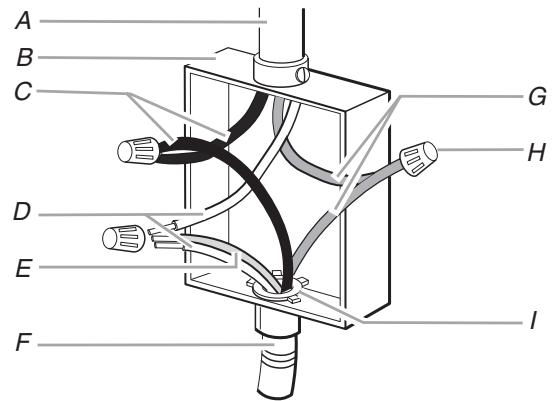
A. Cable from home power supply
B. Junction box
C. Black wires
D. White wires
E. Green (or bare) ground wire (from oven)
F. 4-wire flexible conduit from oven
G. Red wires
H. UL listed wire connectors
I. UL listed or CSA approved conduit connector
- Connect the 2 black wires (C) together using a UL listed wire connector.
- Connect the 2 white wires (D) and the green (or bare) ground wire (of the oven cable) using a UL listed wire connector.
- Connect the 2 red wires (G) together using a UL listed wire connector.
- Install junction box cover.
WARNING
Excessive Weight Hazard
Use two or more people to move and install oven.
Failure to do so can result in back or other injury.
- Using 2 or more people, lift oven partially into cabinet cutout. Use the oven opening as an area to grip.
NOTE: Push against seal area of oven front frame when pushing oven into cabinet. Do not push against outside edges.
- Push against seal area of front frame to push oven into cabinet until shipping feet almost contact cabinet.
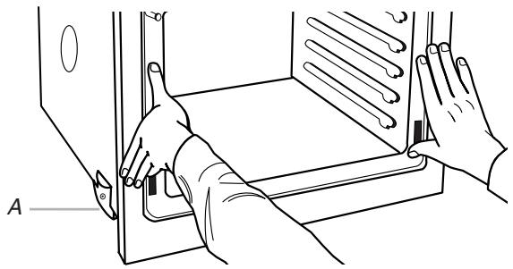
A. Shipping foot
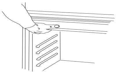
- On models with shipping feet, use a Phillips screwdriver to remove screws attaching the shipping feet.
- Push oven completely into cabinet and center oven into cabinet cutout.
- Securely fasten oven to cabinet using the # 8-14 x 1" screws (2 for single oven, 4 for double oven) provided. Insert the screws through holes in mounting rails. Do not overtighten screws.
A. Mounting rail
B. Insert screw.
- On some models, the oven vent is taped to the side of the oven. See the following instructions to install.
Insert the vent tabs (B) into slots (A) in the oven frame.
- With one # 8 - 18 × 3% screw (C) for each side of the vent, fasten vent securely to the oven.
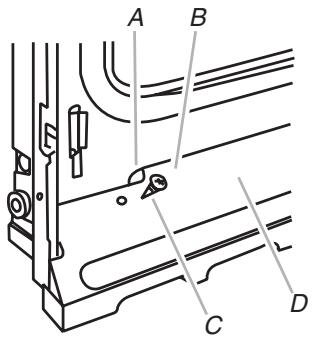
A. Oven frame slot
B. Vent tab
C. # 8-18 x 3 / 8 " screw
D. Oven vent
- Slide top end of each trim piece upward onto oven side rails.
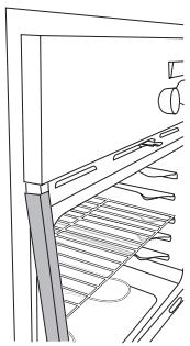
- Push each trim piece into place at bottom of trim.
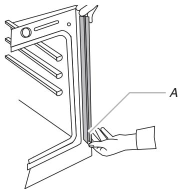
A. Push trim into place and replace screw.
- Use the 8 - 18 × 3% screws, located in the screw bag assembly, to attach each trim piece to oven.
- Replace oven racks.
- Replace oven door by inserting ends of hinges into hinge slots in the oven frame.
- Push hinges in as far as they will go and open the oven door. You should feel the oven door drop into place.
- Rotate both hinge latches back to the locked position.
- Check that door is free to open and close. If it is not, repeat the removal and installation procedures. See "Prepare Built-In Oven" section.
- Repeat for lower oven door.
- Reconnect power.
- Display panel will light briefly, and "PF" should appear in the display.
- If display panel does not light, please reference the "Assistance or Service" section of the Use and Care Guide or contact the dealer from whom you purchased your oven.
Complete Installation
- Check that all parts are now installed. If there is an extra part, go back through the steps to see which step was skipped.
- Check that you have all of your tools.
- Dispose of/recycle all packaging materials.
- For oven use and cleaning, read the Use and Care Guide.
Check Operation of Single Oven
- Turn power on. "PF" should appear in the display.
- Press CUSTOM BROIL. "BROIL" will appear in the display.
- Press START. Make sure the oven door is closed and the "ON" light is shown in the display.
If oven(s) does not operate, check the following:
Household fuse is intact and tight; or circuit breaker has not tripped.
Electrical supply is connected.
See "Troubleshooting" section in the Use and Care Guide.
- When oven has been on for 5 minutes, feel for heat.
If you do not feel heat or if an "F" followed by a number appears in the display, turn off the oven and contact a qualified technician.
- Press OFF/CANCEL.
Check Operation of Double Oven
- Turn power on. "PF" should appear in the display.
- Press UPPER OVEN or LOWER OVEN, to select the oven you are testing.
- Repeat "Check Operation of Single Oven" steps 2-5.
To set the clock and other oven functions, refer to the Use and Care Guide.
If you need Assistance or Service:
Please reference the "Assistance or Service" section of the Use and Care Guide or contact the dealer from whom you purchased your built-in oven.
SECURITE DU FOUR ENCASTRE
National Fire Protection Association
One Batterymarch Park
Quincy, MA 02269
CSA International
8501 East Pleasant Valley Road
Cleveland, OH 44131-5575
- INSTALLATION INSTRUCTIONS
- 27" (68.6 CM) AND 30" (76.2 CM) ELECTRIC SINGLE
- AND DOUBLE BUILT-IN OVEN
- INSTRUCTIONS D'INSTALLATION
- FOUR ÉLECTRIQUE ENCASTRÉ DE 27" (68,6 CM) ET 30"
- (76,2 CM) - SIMPLE ET DOUBLE
- Table of Contents/Table des matieres
- BUILT-IN OVEN SAFETY
- Your safety and the safety of others are very important.
- DANGER
- WARNING
- INSTALLATION REQUIREMENTS
- Tools and Parts
- Tools needed
- Parts needed
- Parts supplied
- Location Requirements
- 27'' (68.6 cm) models
- 30'' (76.2 cm) models
- Cabinet Dimensions - Single Ovens
- Single Oven Undercounter (without cooktop installed above)
- 27^ (68.6 cm) models
- 30^ (76.2 cm) models
- Single Ovens Installed in Cabinet
- 27" (68.6 cm) models
- Product Dimensions - Double Ovens
- 30^ (76.2cm) models
- Electrical Requirements
- Electrical Connection
- Prepare Built-In Oven
- Remove Oven Door
- Remove Oven Trim
- Make Electrical Connection
- Electrical Shock Hazard
- 4-Wire Cable from Home Power Supply
- 3-Wire Cable from Home Power Supply - U.S. Only
- Complete Installation
- Check Operation of Single Oven
- If oven(s) does not operate, check the following:
- Check Operation of Double Oven
- If you need Assistance or Service:
- SECURITE DU FOUR ENCASTRE
Brand : WHIRLPOOL
Model : INSTALLATION
Category : Home Appliance