
SB-900 - Subwoofer ATLANTIC - Free user manual and instructions
Find the device manual for free SB-900 ATLANTIC in PDF.


| Model | SB-900 |
| Type | Powered Subwoofer |
| Bass Driver | 8" long-throw |
| Output Power (RMS) | 125W |
| Amplifier Distortion | <0.5% |
| Frequency Response | 32Hz - 200Hz ±3 dB |
| Peak Output | 103dB SPL into 2000 cubic feet |
| Dimensions (W x H x D) | 11 x 13 x 13.125 in (275 x 330 x 333 mm) |
| Additional Height for Feet | 1.75 in (45 mm) |
| Additional Depth for Knobs & Grille | 1.5 in (38 mm) |
| Weight | 28 lbs (12.7 kg) |
| Power Requirements | 110-120/220-240V, 50/60Hz, 250W Max |
| Standby Mode | Automatic or always on (selectable) |
| Phase Switch | 0° or 180° for acoustic matching |
| Bass Level Control | Adjustable bass level |
| Low-Pass Crossover Frequency | 55Hz to 200Hz adjustable, 18dB/octave |
| Low-Pass Switch | Low-Pass or Bypass for pre-filtered signals |
| Audio Inputs | Low Level (RCA) and High Level (speaker wire) |
| Audio Outputs | High Level Output for main speakers |
| Voltage Selector Switch | 115V or 230V |
| Enclosure Material | Medium Density Fiberboard (MDF) |
| Cleaning Instructions | Use a soft cloth, dry or slightly damp with water. Avoid wetting seams. |
| Safety Notices | Do not expose to rain or moisture. Do not block ventilation. No user-serviceable parts inside. |
Frequently Asked Questions - SB-900 ATLANTIC
User questions about SB-900 ATLANTIC
0 question about this device. Answer the ones you know or ask your own.
Ask a new question about this device
Download the instructions for your Subwoofer in PDF format for free! Find your manual SB-900 - ATLANTIC and take your electronic device back in hand. On this page are published all the documents necessary for the use of your device. SB-900 by ATLANTIC.
USER MANUAL SB-900 ATLANTIC
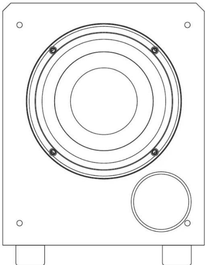
High Performance Powered Subwoofer
2
Safety Precautions
Model SB-900 Powered Subwoofer
Safety Precautions

CAUTION: To reduce the risk of electric shock, do not cover (or back). No user serviceable parts inside. Refer to qualified personnel.
WARNING: To reduce the risk of fire or electric shock, do not expose this appliance to rain or moisture. This device generates a fair amount of heat. Make sure nothing blocks the ventilation to the rear panel of the unit.
The lightning flash with arrowhead, with in an equilateral triangle, is intended to alert the user to the presence of uninsu lated “dangerous voltage” within the product’s enclosure that may be of sufficient magnitude to constitute a risk of electrical shock to persons.

The exclamation point within an equilateral triangle is intended to alert the user to the presence of important operating maintenance (servicing) instructions in the literature accompanying the appliance.
Model SB-900 Specifications
Bass Driver 8" long-throw
Output Power 125W RMS
Distortion (amplifier) <0.5%
Frequency Response 32Hz - 200Hz ±3 dB
Peak Output 103dB SPL into 2000 cubic Feet
ove the
Dimensions (WxHxD) 11 x 13 x 13.125 in; 275 x 330 x 333mm
add 1.75" (45mm) H for feet
add 1.5" (38mm) D for knobs & grille
Weight
28lbs/12.7kg
Power Requirements
110-120/220-240V, 50/60Hz, 250W Max

For Future Reference
Record your serial numbers and date of purchase here:
Model Number
Serial Number
Date of Purchase
The serial number is found on the back panel.
Copyright © 2010 Atlantic Technology International.
Specifications are those in effect at the time of printing. Atlantic Technology reserves the right to change specifications or designs at any time without notice.
Instruction Manual
SB-900 Subwoofer Rear Panel
Figure 1
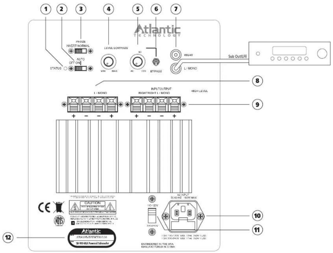
① Status LED
This will be green for "on" condition, red for "standby"
② Standby Switch
When in ON position, the amplifier will always be on. When in the AUTO position, the amplifier will be in Automatic Standby Mode.
③ Phase Switch
This switch allows precise acoustic matching with satellite speaker systems whose output may be phase reversed. Try in both the highest and lowest positions — use the position that results in the strongest bass output.
④ Bass Level Control
Use this control to set the level of bass desired
5 Low-Pass Control
An adjustable (55Hz to 200Hz) @ 18dB per octave low-pass crossover.
6 Low-Pass Switch
When in the LOW-PASS position, adjustment of the crossover can be made by the Crossover Control. If being fed a pre-filtered or THX signal, place the switch at the BYPASS position.
⑦ Low Level Input
Use the input to connect to the subwoofer or LFE line out from your processor/receiver.
⑧ High Level Output
Connect main Left/Right speakers here when using the High Level Input.
⑨ High Level Input
If your electronics do not have a line-level sub out, connect the Left-Right speaker terminals of your electronics to these connections. Set the SB-900's crossover to "Lowpass," and adjust accordingly.
10 AC Input
Use the included power cord to connect your amplifier to a wall outlet.
⑪ Voltage Select Switch
Voltage switch for use in different countries. This switch will be set when you receive the unit. Change this setting only when you are sure your application requires it. For US, the switch should be set to the 115V position.
12 Product Serial Number
Write this number in the space provided on page 2 for future reference.
Placement and Operation
Generally speaking, the best location for your new subwoofer is the front of the room, close to a corner (Figure 5). Every room has its own unique sound characteristics, and flexibility in the exact placement of the subwoofer is always desirable. The closer the subwoofer is placed a wall and especially a corner, the more and deeper the bass response you will hear. However, in some rooms, corner placement can produce a "one note" boomy effect. Under such circumstances the subwoofer may work better away from the corner. Experiment to find the best position in your room.
Figure 5
Typical arrangement for a single subwoofer in a home theater.
![graph TD A["Start here"] --> B["Move to corner for more bass"] B --> C["Move away from wall for less bass"]](/content/2026/05/1001642/images/b63772c95e66db25121978e78ec28143cb1151281cccca95a90f1757984c93b9.jpg)
Using the Subwoofer Low-Pass Control

NOTE: Set this control to "Bypass" if you are using a receiver that has its own subwoofer crossover. Set this control to "LOW-PASS" if your electronics do not have a bass management function. The goal is to optimize the performance of the system by ensuring that the subwoofer and satellites
produce a cohesive and well integrated sound "picture."
Most surround sound receivers and processors offer a choice of cross-overs, typically between 60 Hz and 150 Hz. We recommend using a setting between 120Hz and 150Hz when using small speakers such as those in a soundbar. Consult your electronics owner's manual for more details.
It's generally undesirable to have the main speakers and the subwoofer overlap too much. Larger speakers means a lower Low-pass crossover frequency, smaller speakers means a higher Low-pass crossover frequency. Consult the manufacturer's specified low frequency response for your main speakers to determine the appropriate Low-pass setting on your subwoofer. In the end, however, a little time spent experimenting will generally result in dramatically better bass response.
Care of Your Subwoofer
Your subwoofer is constructed from Medium Density Fiberboard. MDF is a non-resonant material ideal for speaker system enclosures. To clean the cabinet you may use a soft cloth either dry or slightly dampened with clean water. Be careful not to wet the cabinet or allow any water to enter the cabinet seams. Avoid placing your speakers in direct sunlight or near a source of heat that may, over time, damage the finish.
Subwoofer Troubleshooting Guide
Once your subwoofer is set up, you should have many years of maintenance free enjoyment from your system. However, if you should encounter a problem, refer to the following guide to help you find the solution. If a problem persists, you should contact your local authorized Atlantic Technology dealer.
| Problem | Possible Cause | Possible Solution |
| No bass output | AC power cord unplugged or plugged into a non-working outlet. | Plug into a working outlet. |
| Input cables not securely connected or defective. | Check all connections, then try another input cable. | |
| Audible buzz or hum | Input cable not securely connected or defective. | Check all connections, then try another input cable. |
| Ground loop through antenna or cable TV system input. | Test by disconnecting antenna and/or cable system input leads. If hum goes away, install isolation balun(s) at that point. |
015-1099




Brand : ATLANTIC
Model : SB-900
Category : Subwoofer