
TC 2010 - Rasentrimmer TORO - Kostenlose Bedienungsanleitung
Finden Sie kostenlos die Bedienungsanleitung des Geräts TC 2010 TORO als PDF.


| Marke | Toro |
| Modell | TC 2010 |
| Produkttyp | Kantenmäher (Freischneider) |
| Motor | Zweitaktmotor |
| Kraftstoff | Benzin-Öl-Gemisch 40:1 |
| Empfohlenes Öl | Toro Easy Mix Zweitaktöl oder NMMA/BIA-TCW zertifiziertes Öl |
| Zündkerze | Champion CJ8Y oder gleichwertig, Elektrodenabstand 0,6 mm |
| Schneidfaden | Monofilament, Durchmesser 0,080 Zoll |
| Fadenlänge pro Spule | max. 38 Fuß (ca. 11,6 m) |
| Schneidkopf | Automatischer Fadenvorschub durch Aufsetzen auf den Boden |
| Kupplung | Fliehkraftkupplung, Einschaltdrehzahl ca. 3600–4200 U/min |
| Leerlaufdrehzahl | 2600–3200 U/min (Schneidkopf sollte nicht rotieren) |
| Startsystem | Seilzugstarter |
| Choke | Manuell |
| Schalldämpfer | Optionaler Funkenfänger (Teil #77-2120) |
| Sicherheitsmerkmale | Schutzschild, Sicherheitsaufkleber, Motorschalter |
| Gewicht (ca.) | Nicht angegeben (schätzungsweise 4–5 kg) |
| Garantie | 2 Jahre für private Nutzung, 90 Tage für gewerbliche Nutzung |
| Hersteller | The Toro Company, Minneapolis, MN, USA |
Häufig gestellte Fragen - TC 2010 TORO
Benutzerfragen zu TC 2010 TORO
0 Frage zu diesem Gerät. Beantworten Sie die, die Sie kennen, oder stellen Sie Ihre eigene.
Eine neue Frage zu diesem Gerät stellen
Laden Sie die Anleitung für Ihr Rasentrimmer kostenlos im PDF-Format! Finden Sie Ihr Handbuch TC 2010 - TORO und nehmen Sie Ihr elektronisches Gerät wieder in die Hand. Auf dieser Seite sind alle Dokumente veröffentlicht, die für die Verwendung Ihres Geräts notwendig sind. TC 2010 von der Marke TORO.
BEDIENUNGSANLEITUNG TC 2010 TORO

MODEL NO. 51637-0000001 & UP
OPERATOR'S MANUAL
TC2010 GAS TRIMMER

SAFETY INSTRUCTIONS
To assure maximum safety, optimum performance, and to gain knowledge of the product, it is essential that you or any other operator of the trimmer read and understand the contents of this manual before the motor is ever started. Pay particular attention to the safety alert symbol which means CAUTION, WARNING, OR DANGER — “personal safety instruction.” Read and understand the instruction because it has to do with safety. Failure to comply with instruction may result in personal injury.
- Operate the machine only after reading and understanding the contents of this manual. A replacement manual is available by sending complete model and serial numbers to: The Toro Company, 8111 Lyndale Avenue South, Minneapolis, Minnesota 55420.
- Never allow children to operate trimmer. It is not a toy. Never allow adults to operate unit without first reading Operator's Manual.
- Become familiar with the controls and know how to stop the engine quickly.
- The following articles of apparel are strongly recommended and are required by some local safety and insurance regulations:
A. Safety glasses/goggles - REQUIRED
B. Safety shoes
C. Long pants
D. A long-sleeved shirt
E. Ear plugs
Dress properly—Do not wear loose clothing or jewelry. They can be caught in moving parts. Always wear substantial footwear and long pants. - Keep the area of operation clear of all persons, particularly children and pets.
-
Never operate trimmer when you are fatigued.
-
Keep all shields, safety devices, and decals in place. If a shield, safety device or decal is defective or damaged, repair or replace it before operating the machine.
- Gasoline is highly flammable. Trimmer is fueled with a mixture of gasoline and oil. Indoor or outdoor heat, sunlight or engine heat may cause flammable gasoline vapors which pressurize trimmer fuel tank. Observe all the following precautions:
A. Use an approved fuel container for storing the gasoline/oil mixture.
B. Do not fill tank when engine is hot or running.
C. Do not smoke while handling gaso- line.
D. Fill fuel tank outdoors and up to about one-half inch (13 mm) from the top of the tank, not the filler neck.
E. Wipe up any spilled gasoline before starting the engine.
F. Before transporting trimmer in a vehicle, drain all gasoline from fuel tank.
G. Store trimmer in a cool, ventilated place.
H. Lay trimmer on a flat surface so fuel does not contact the gas cap when not operating.

SAFETY INSTRUCTIONS
- Do not run the engine in a confined area without adequate ventilation. Exhaust fumes are hazardous and could be deadly.
- Always be sure of your footing. Keep a firm hold of the handles with both hands and walk, never run, during operation. Shut the engine off before preceding to the next area of operation.
- The trimmer is intended to be used as a means of trimming grassy and weedy areas only. DO NOT use the trimmer for such things as tree pruning or hedge trimming. Do not use the trimmer for vertical edging. The grass shield is designed only for horizontal trimming.
- Do not put hands or feet near or under rotating parts. Keep clear at all times.
- If the trimmer should start to vibrate abnormally, stop the engine and check immediately for the cause. Vibration is generally a warning of trouble.
- Avoid using the trimmer near rocks, gravel, stones or other debris which could be picked up and thrown or personal injury could result.
-
Use trimmer only in daylight or good artificial light.
-
Shut off engine and be certain all moving parts have completely stopped rotating before inverting trimmer.
- Never use wire or metal reinforced string in place of monofilament cutting line.
- Wear a long sleeve or other similar arm protection to avoid possible contact with hot engine surfaces.
- Before servicing or making adjustments to the machine, stop the engine and pull wire off spark plug to prevent accidental starting of the engine.
- Assure entire machine is in good condition. Keep all nuts, bolts, and screws properly tightened.
- If major repairs are ever needed or if assistance is desired, contact an Authorized Toro Service Dealer.
- To reduce potential fire hazard, keep the engine area free of excessive oil, grass, leaves and accumulation of dirt.
- If the engine must be running to perform a maintenance adjustment, keep hands, feet, clothing and any part of the body away from any moving parts. Keep everyone away.

SAFETY DECALS
Safety decals and instructions are easily visible to the operator and are located near any area of potential danger. Replace any decal that is damaged.

ON MUFFLER SHIELD (Part No. 63-8440)

ON DRIVE SHAFT TUBE (Part No. 46-9480)
ON ENGINE HOUSING
(Part No. 65-2690)

TABLE OF CONTENTS
Page
Assembly Instructions 3
Before Operating 4-5
Operating Instructions 5-7
Maintenance 8-13
Replacing Cutting Line 8-9
Adjusting Carburetor 9
Servicing Muffler 9-10
Replacing Spark Plug 10
Cooling System Service ..... 10
Servicing Air Cleaner ..... 11
Cleaning Trimmer Head ..... 11-12
Replacing Fuel Filter 12
Adjusting Throttle Control ..... 12
Lubricate Flexible Shaft 13
Preparing Trimmer for Storage ... 13
Optional Spark Arrestor Muffler ..... 13
Product Identification 14
Toro Service Support 14
Accessories 14
Troubleshooting Chart 15
The Toro Promise
ASSEMBLY INSTRUCTIONS
MOUNT CUTTER HEAD (Fig. 1)
- Remove plastic shipping cap from end of drive shaft tube to expose flexible shaft.
Note: Hold flexible shaft in drive shaft tube as it may slide out of tube when cap is removed.
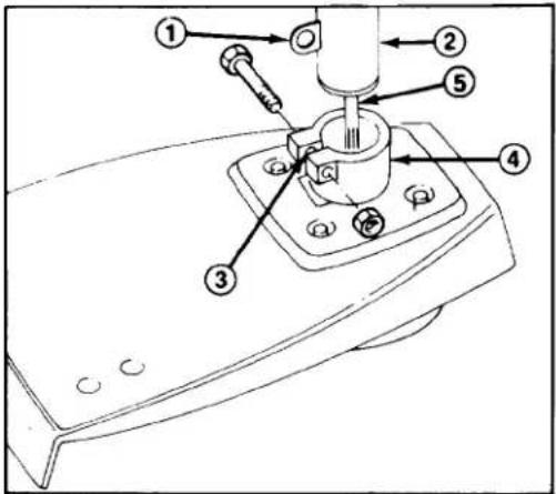
Figure 1
-
Retaining clips
-
Drive shaft tube
-
Slotted area
-
Bearing
housing
-
Flexible shaft
-
Insert flexible shaft into square hole in bearing housing.
-
Align retaining clips on drive shaft tube with slotted area in bearing housing.
-
Insert drive shaft tube and flexible shaft into bearing housing. Tube should slide into bearing housing until holes in retaining clips are aligned with mounting holes in bearing housing.
- Secure tube and retaining clips to bearing housing with capscrew and lock-nut.
SECURE SUPPORT HANDLE (Fig. 2)
- Rotate support handle upright and adjust to comfortable operating position. Tighten handle knob securely (Fig. 2).
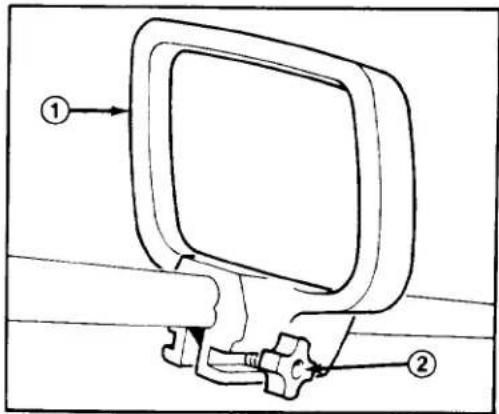
Figure 2
- Support handle 2. Handle knob
Note: Do not remove tape from cutting line before initial start up.
BEFORE OPERATING

WARNING
DANGER: Gasoline is extremely flammable and explosive under certain conditions. Do not smoke when handling fuel and keep fuel far away from open flames and sparks. Never buy more than a 30 day supply of gasoline. Store it in an approved container. Keep gasoline out of reach of children.
Refuel outdoors and only when engine is cold. Do not fill tank full. Fill tank to within 1/4" to 1/2" (6 to 13 mm) from top of tank, not into filler neck. This space is for expansion of fuel. Use funnel or spout to prevent spilling. Wipe up any spilled gas.
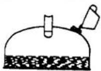
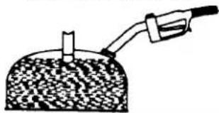
MIX GASOLINE AND OIL — 40:1 RATIO
- APPROVED MIXTURE—For simplicity and best engine performance, mix the contents of one 3.2-ounce bottle of Toro "EASY MIX" Two-Cycle Oil with one gallon of fresh, unleaded regular gasoline. Leaded regular gasoline may be used if unleaded regular is not available.
Toro Two-Cycle Oil is specially formulated to provide superior lubrication, make starting easy, and prolong engine life. If Toro Two-Cycle Oil is not available, mix one gallon of gasoline and 3.2 ounces of another high grade two-cycle oil that has the NMMA or BIA-TCW certification printed on the label.
NEVER USE AUTOMOTIVE OIL (i.e. SAE 30, 10W30 etc.), TWO-CYCLE OIL THAT IS NOT CERTIFIED NMMA/BIA-TCW, OR THE WRONG MIX RATIO BECAUSE THE ENGINE CAN BE DAMAGED, AND IT WOULD NOT BE COVERED BY THE TORO WARRANTY.
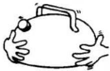
- Mixing Gasoline and Oil—Pour correct amount of two cycle oil into an approved gasoline container and add a half gallon of gasoline. Install cap on gaso-
line container and shake the container to mix oil and gas thoroughly. Remove cap and add remaining amount of gasoline.
IMPORTANT: NEVER USE METHANOL, GASOLINE CONTAINING METHANOL, GASOHOL CONTAINING MORE THAN 10% ETHANOL, PREMIUM GASOLINE, OR WHITE GAS BECAUSE ENGINE FUEL SYSTEM DAMAGE COULD RESULT.
DO NOT USE FUEL ADDITIVES OTHER THAN THOSE MANUFACTURED FOR FUEL STABILIZATION DURING STORAGE SUCH AS TORO'S PRESERVIT OR A SIMILAR PRODUCT. TORO'S PRESERVIT IS A PETROLEUM DISTILLATE BASED CONDITIONER/STABILIZER. TORO DOES NOT RECOMMEND STABILIZERS WITH AN ALCOHOL BASE SUCH AS ETHANOL, METHANOL OR ISOPROPYL. ADDITIVES SHOULD NOT BE USED TO TRY TO ENHANCE THE POWER OR PERFORMANCE OF MACHINE.
NOTE: Do not mix gasoline and oil in the product fuel tank. Oil that is at room temperature mixes easier and more thoroughly than cold oil.
40:1 GAS/OIL Mixing Chart
| U.S. GALLON | |
| Gasoline | Oil |
| 1 gallon | 3.2 oz. |
| 2 gallon | 6.4 oz. |
BEFORE OPERATING
①
Add oil to small amount of gasoline.
②
Install cap and shake can to mix.
③
Add remaining amount of gasoline.
natural_image
Simple line drawing of a tool injecting liquid into a granular substance (no text or symbols)Figure 3
OPERATING INSTRUCTIONS
STARTING AND STOPPING (Fig. 4 & 5)
Cold Engine
- Lay trimmer on a flat surface with engine in upright position.

Figure 4
- Ignition switch 2. Throttle trigger
-
Move ignition switch to "ON" position.
-
Move choke lever to "CLOSED" position.
-
Push the carburetor primer bulb until fuel drains from the carburetor through fuel tube to the fuel tank.
- Squeeze throttle trigger to full throttle position and hold in this position.
- Pull recoil starter handle out slowly until starter ratchets are engaged, then pull handle with short, sharp strokes until engine starts. Move choke lever to OPEN position. If engine fails to start, repeat all steps above.
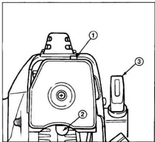
Figure 5
- Choke lever
-
Primer bulb
-
Recoll starter
Note: Always pull starter rope straight up. Pulling rope at an angle will force it against the eyelet and cause it to fray and wear more quickly. Hold the starter handle when rope retracts. Never allow it to snap back from extended position. The rope can fray or snag and the starter can be damaged.
Warm Engine
- Move ignition switch to "ON" position.
- Move choke lever to OPEN position.
- Squeeze throttle trigger to full throttle position and hold.
OPERATING INSTRUCTIONS
- Pull recoil starter handle out slowly until starter ratchets are engaged, then pull handle with short, sharp strokes until engine starts. If engine fails to start, repeat all steps above.
Note: Use of the primer bulb is not required to start a warm engine. However, if a combination of a hot engine and warm outside temperatures induces a vapor lock condition, use the primer bulb. This will introduce cool fuel into the carburetor and break the vapor lock.
To Stop Engine:
- Release throttle trigger and move ignition switch to "OFF" position.

WARNING
The cutter head continues to rotate for a few seconds after the engine is shut off. Do not place any part of the body in the cutter head area until you are sure the cutter head has stopped.
CENTRIFUGAL CLUTCH
This machine is equipped with a centrifugal clutch which is designed to engage when engine speed reaches approximately 3600 - 4200 RPM. This is the point at which the cutter head begins to rotate. The clutch will slip to prevent possible engine damage should the cutter head be prevented from rotating. Should this situation occur, STOP ENGINE, remove obstruction, and resume operation.
ENGINE OPERATION
- Allow the engine to run at idle speed a few minutes to warm up before using. IMPORTANT: The cutting head should not rotate at engine idle speed. If cutting head rotates at idle, decrease idle speed by adjusting idle stop screw. Refer to Adjusting Carburetor, page 9.
Note: DO NOT have engine under load during this warm up period.
- When starting trimmer engine initially, check carburetor adjustments. Refer to Adjusting Carburetor, page 9.
- By squeezing throttle lever, increase engine RPM to speed required for operation before placing trimmer under load.
IMPORTANT: Do not use trimmer at very low engine speeds. Cutting efficiency will be poor and clutch damage could result.
- ALWAYS reduce engine speed to idle when not trimming.
- NEVER operate the engine at high RPM without line extended.
OPERATING TIPS (Figs. 6 & 7)

WARNING
Always wear safety goggles or other suitable eye protection and long pants and shoes while operating trimmer. Wear a long sleeve shirt or other similar arm protection to avoid possible contact with hot muffler surface. Ear protection must be worn when operating trimmer for prolonged periods of time (over 2-1/2 hours).
- The trimmer will cut grass, weeds, ivy, and other similar grasses, and can be used to cut areas around shrubs, foundation walls, along fences, sidewalks, and patios.
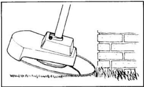
Be sure to inspect area to be trimmed for any wire, cord, or string-like matter which could become entangled in the rotating line. - Do not force the unit. Remember, it is only the tip of the cutting line that does the job. Forcing the line against an object like a foundation wall or fence could cause the line to break (Fig. 6).
OPERATING INSTRUCTIONS
natural_image
Line drawing of a grassy slope with a tool near a brick wall (no text or symbols)Figure 6
- Get comfortable. Make sure support handle adjusting knob is tightened securely before operating trimmer. When trimming you should be standing in a natural position without having to bend over or stand on your toes.

CAUTION
Always be sure of your footing when operating trimmer.
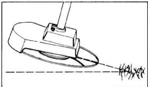
- Slowly move trimmer in a side to side motion into the area being cut, while at the same time, holding the unit at the desired height of cut. Always tip the leading edge of the cutter slightly downward to gain maximum cutting efficiency (Fig. 7).
natural_image
Technical line drawing of a mechanical device emitting a surface, with no visible text or symbolsFigure 7
- The life of your cutting line is dependent upon following the previous trimming techniques, as well as what is being cut, and where the cutting is done. EXAMPLE: Line will wear faster when run against a foundation wall as com-
pared to trimming around a tree. Some line breakage will occur from moving unit too fast, from entanglement with foreign matter, from normal line fatigue, and from attempting to cut thick, stalky weeds in excess of unit's capability.
LENGTHENING CUTTING LINE (Fig. 8)
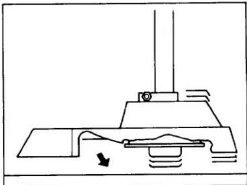
Your Toro trimmer is equipped with an automatic line feeding device so the line can be lengthened without STOPPING THE ENGINE.
natural_image
Pure mechanical diagram showing a lever mechanism with no text or symbolsFigure 8
Note: Engine speed and noise will increase noticeably when line wears down.
- To lengthen line, firmly tap spool on the ground while the engine continues to run at normal cutting RPM (Fig. 8). The line will be fed from the spool and cut off to the proper length by the cutting knife attached to the shield.
Remember to keep the engine speed up while lengthening the line. Just tap the trimmer on the ground; do not hold it on the ground.
Note: The spool cap may wear during normal use of the line advance feature and may require occasional replacement.
Empty spools and spools prewound with 38 feet of cutting line are available through your local Toro Dealer.
Never continue to use spool cap which has been worn through, cracked or has chips out of it.
MAINTENANCE
REPLACING CUTTING LINE (Figs. 9-11)
- To replace cutting line when your factory furnished supply runs out, you may purchase .080" dia. replacement line to rewind the empty spool or prewound replacement spools from your Toro retailer.

WARNING
Shut off engine and be certain cutter head has completely stopped rotating before inverting trimmer.
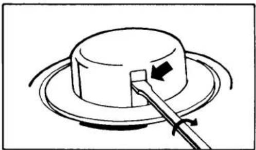
- To remove empty spool, insert medium blade screwdriver in one of two window slots on spool hub and twist screwdriver 1/4 turn. Spool will snap off. Note: Use as wide a screwdriver as will fit in slot so as not to mar cap when twisting.
natural_image
Simple line drawing of a hat with a lever and arrow indicating direction (no text or symbols)Figure 9
- To rewind empty spool, use the following steps:
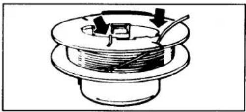
A. Hook one end of line into the grooved notch on spool. Wind line around spool in the direction indicated by arrow on spool in level rows between spool flanges as shown.
Note: Avoid crossover or crisscrossing of line to insure proper line advancing.
B. Do not wind more than 38 feet of line onto spool or allow wound line to extend outside of spool. Only use line .080" dia.
C. Keep line tight on spool by securing in remaining spool notch (Fig. 10).
natural_image
Diagram of a mechanical component with a coil and directional arrows, no text or symbols presentFigure 10

WARNING
Do not use any type of wire or other string-like substance. Use only Toro approved replacement monofilament line of .080 inch diameter. Use of improper monofilament line could result in personal injury.
natural_image
Illustration of hands holding a coiled spring component with a downward arrow indicating compression (no text or symbols)Figure 11
Note: Before reassembly, be sure to thoroughly clean drum and powershaft area and visually inspect for any damaged or worn parts.
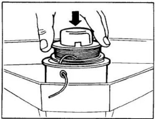
D. The spool and core are keyed. Be sure they are properly aligned when putting spool back on. Thread end of line through eyelet. Pull line free from notch in spool keeping tension on line. (Do not release line tension until spool is installed in drum.) Place spool on keyed core and push in place until you hear it click. Unwind no more than five inches form spool.
MAINTENANCE
- If line should break at the eyelet, remove the spool completely, refeed the cutting line through the eyelet and reassemble spool to trimmer following instructions above.
ADJUSTING CARBURETOR (Fig. 12)
The carburetor has been adjusted at the factory, but an adjustment may be required to compensate for differences in fuel, temperature, and altitude.
IMPORTANT: Before making carburetor adjustments, clean the air filter and muffler and be sure the right amount of line is fed from the trimmer spool.

CAUTION
To prevent personal injury, use extreme caution when an adjustment or maintenance procedure must be performed while the engine is running. Pull wire off spark plug if engine does not have to be running while performing adjustment or maintenance procedures.
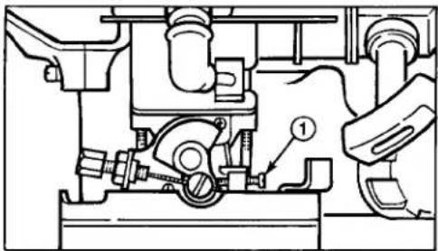
- Start the engine and let it warm up for approximately 3-5 minutes. Do not adjust carburetor when engine is cold. Be sure to perform carburetor adjustment while at a temperature that will be the average outdoor temperature at which the trimmer will be used. Allow the engine to idle. If necessary, readjust the idle speed to keep the engine from stalling (2600-3200 RPM). Turn screw clockwise to increase idle speed, counterclockwise to decrease idle speed.

CAUTION
Engine must be running so final adjustment of the carburetor can be performed. To guard against possible personal injury, keep hands, feet, and face away from concealed, moving, or rotating parts.
natural_image
Technical diagram of a mechanical assembly with labeled component (no readable text or symbols)Figure 12
1. Idle speed screw
Note: When making adjustment turn adjustment screw 1/8 turn at a time and wait for engine to respond to change. IMPORTANT: Cutter head should not rotate at idle speed.
SERVICING MUFFLER (Fig. 13 & 14)
If engine speed or power decreases drastically, inspect and clean muffler and exhaust port of carbon deposits to relieve back pressure.
- Remove two (2) screws securing engine cover to trimmer (Fig. 13).
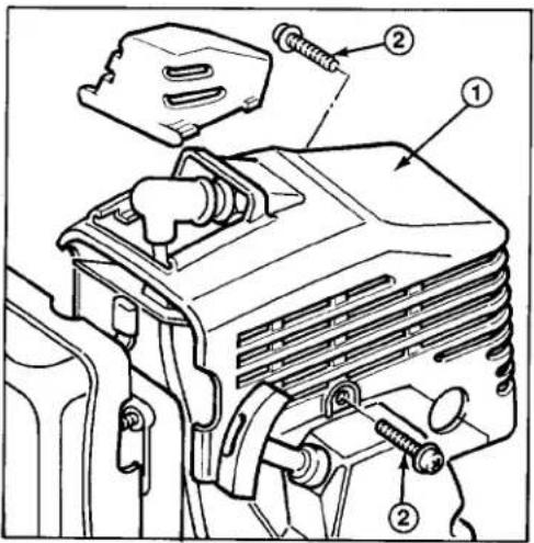
Figure 13
1. Engine cover
2. Screws (2)
MAINTENANCE
- Remove two (2) nuts securing muffler to engine (Fig. 14). Remove muffler.
- Clean any carbon build-up from muffler port (Fig. 14).
- Pull recoil starter slowly to rotate the engine crankshaft until the piston totally covers the exhaust port (Fig. 14). Clean the exhaust port area by using a clean, flat piece of hard wood. Remove all loose particles.
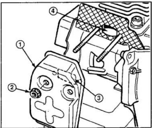
Figure 14
- Muffler
-
Nuts
-
Muffler port
-
Exhaust port
IMPORTANT: Use extreme care when cleaning exhaust port. Stay clear of the piston so it will not be damaged. Piston damage can cause early engine failure.
- Reinstall muffler to engine.
- Reinstall engine cover and tighten all fasteners securely.
REPLACING SPARK PLUG (Fig. 15)
Use a Champion CJ8Y spark plug or equivalent. Correct air gap is .025" (0.6 mm). Remove plug after every 25 operating hours and check its condition.
- Stop engine. Remove spark plug cover by squeezing sides and sliding off engine cover (Fig. 15). Pull wire off spark plug.
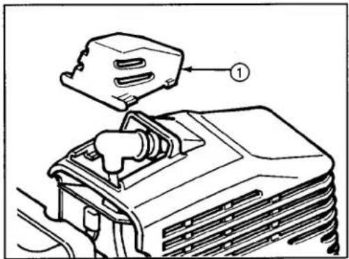
Figure 15
1. Spark plug cover
- Clean around spark plug and remove plug from cylinder head.
IMPORTANT: Replace a cracked, fouled or dirty spark plug. Do not sand blast, scrape or clean electrodes because engine damage could result from grit entering cylinder.
- Set air gap at .025" (0.6 mm) (Fig. 16). Install correctly gapped spark plug and gasket seal. Tighten plug firmly to 9 ft-lb (1.2 Kg-m).
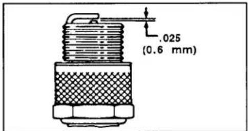
Figure 16
COOLING SYSTEM SERVICE
To avoid overheating and possible engine damage, visually inspect the cooling air inlet for debris obstructing the air passages, muffler, and also the cooling fins around the cylinder after each use. Remove any contamination by using a flat piece of wood shaped so it will pass between the fins.
MAINTENANCE
SERVICING AIR CLEANER (Fig. 17)
After every 25 hours of operation inspect and clean air cleaner.
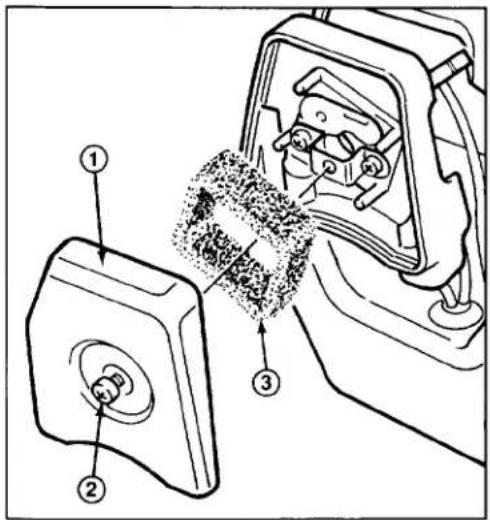
Figure 17
-
Air cleaner cover
-
Screw
-
Foam filter
-
Remove one (1) screw securing air cleaner cover.
- Carefully remove foam filter.
- Wash foam filter in a soap and water solution and thoroughly dry. If filter shows any sign of damage, replace it.
- Saturate the foam filter with one teaspoon (5 ml) of SAE 30 oil. Squeeze filter to distribute oil evenly and to remove excess oil. A damp element is desirable.
- Reinstall air cleaner components as shown in Figure 17.
CLEANING TRIMMER HEAD
(Figs. 18 & 19)
Stringy weeds or other debris may become wound around powershaft. Trim-
mer head assembly must be removed and cleaned periodically.
- Drain gasoline from fuel tank. Remove spark plug cover by squeezing sides and sliding off engine cover (Fig. 15). Pull wire off spark plug.
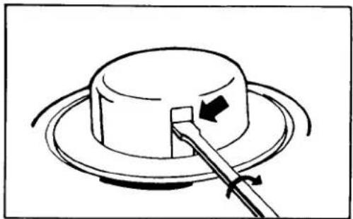
- Insert medium blade screwdriver in one of two window slots on spool hub and twist screwdriver 1/4 turn. Spool will snap off.
Note: Use as wide a screwdriver as will fit in slot so as not to damage cap when twisting.
natural_image
Simple line drawing of a hat with a handle and arrow indicating rotation (no text or symbols)Figure 18
- Hold drum securely and unscrew spool core counter-clockwise. This will unscrew the driver.
- Remove washer and compression spring, and slide drum off powershaft.
- Clean debris from inside and outside of drum and any wrapped around powershaft.
- Slide drum onto powershaft, assuring roll pin fits into slot on top of drum.
- Install compression spring, washer, spoolcore, and driver onto powershaft.
- The spool and spoolcore are keyed. Be sure they are properly aligned when putting spool back on. Thread end of line through eyelet, place spool on keyed core, and push in place until you hear it click.
MAINTENANCE
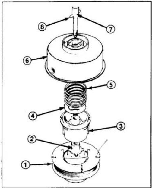
Figure 19
- Spool hub
- Driver
- Spool core
- Washer
-
Compression spring
-
Drum
- Power shaft assembly
- Roll pin
REPLACING FUEL FILTER (Fig. 20)
After every 25 hours of operation, remove and replace fuel filter.
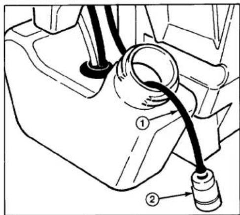
Figure 20
-
Suction hose
-
Fuel filter
-
Drain gasoline from fuel tank. Start engine and let it run at idle speed until it stops and all fuel is expended.
- Remove fuel tank cap. Invert trimmer and shake until end of suction hose is accessible or passes through fuel tank opening.
Alternate Method: Insert a clean wire with a hooked end into tank, hook suction hose above weight, and carefully pull hose out fuel tank opening.
- Replace fuel filter and reinstall suction hose into tank.
- Reinstall fuel tank cap.
ADJUSTING THROTTLE CONTROL (Fig. 21)
- Squeeze throttle trigger and note travel of throttle shaft plate.
- When in full throttle position, throttle plate should make contact with stop.
- When in idle position, throttle plate should stop just before making contact with idle screw. There should be a small amount of slack in cable.
- Loosen jam nut on throttle cable and adjust, if necessary, until desired positions are attained. Tighten jam nut and recheck throttle operation.
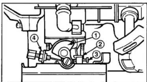
Figure 21
- Throttle shaft plate
-
Stop
-
Idle screw
-
Jam nut
MAINTENANCE
LUBRICATE FLEXIBLE SHAFT
The flexible drive shaft has been evenly greased at the factory. After approximately 40 hours of operation, the flexible drive shaft should be removed from the drive shaft housing and all surfaces of it should be evenly greased with No. 2 general purpose lithium base grease. To remove flexible drive shaft from drive shaft housing, first remove cutter head assembly by reversing assembling instructions in Cleaning Trimmer Head, pages 11-12. Then pull flexible drive shaft from drive shaft housing.
PREPARING TRIMMER FOR STORAGE
- For long term storage, it is recommended that gasoline be drained from fuel tank. After fuel is drained, start engine and let it idle until all fuel is consumed and engine stops. If gasoline is not drained, gum-like varnish deposits will form and cause poor engine operation, even starting problems. Fuel can be left in gas tank only if a fuel additive, such as Toro's Preservit, is added to gasoline before storing. Toro's Preservit is a petroleum distillate based conditioner/stabilizer. Toro does not recommend stabilizers with an alcohol base, such as ethanol, methanol or isopropyl. Use fuel additive in recommended quantities as specified on container.
Under normal conditions, all fuel additives remain effective in fuel for 6–8 months.
- If trimmer is stored with fuel and a fuel additive in gas tank, lay trimmer on a flat surface so fuel does not contact gas cap.
-
Remove dirt and grime from external parts of trimmer housing. Also clean the cooling system: refer to Cooling System Service, page 10.
-
Pull wire off spark plug, clean area around plug so foreign matter cannot fall into cylinder when plug is removed. Remove plug from cylinder head and pour one teaspoon (5 ml) of 2 cycle oil into spark plug hole. Pull recoil starter handle slowly to distribute oil on inside of cylinder. Reinstall spark plug and tighten it to 9 ft-lbs (1.2 Kg-m). If torque wrench is not used, tighten plug firmly. DO NOT INSTALL WIRE ON SPARK PLUG.
-
Check condition of cutter head; replace line, if necessary; refer to Replacing Cutting Line, pages 8–9.
- Clean the air cleaner if necessary: refer to Servicing Air Cleaner, page 11.
- Check and tighten all screws, bolts, nuts and mating parts. If any part is damaged, repair or replace it.
- Store trimmer in a clean, dry place. Cover trimmer to protect it and keep it clean.
OPTIONAL SPARK ARRESTOR MUFFLER—PART #77-2120
If a spark arrestor muffler is required because of local, state or federal regulation, it may be purchased at your local Authorized TORO Service Dealer. If trimmer is operated on any California forest, brush or grass covered land without a properly operating spark arrestor muffler, the operator is violating state law, Section 4442 Public Resources Code.
PRODUCT IDENTIFICATION
A model number and a serial number decal is located on the drive shaft tube. Always refer to specific numbers on this decal in correspondence or when replacement parts are needed.
TORO SERVICE SUPPORT
If help—concerning safety, set-up, operation, and maintenance or troubleshooting—is ever needed, contact the local Authorized TORO Service Dealer or Distributor. Refer to the "Yellow Pages" for assistance. In addition to skilled service technicians, the dealer and distributor have factory approved accessories and replacement parts. Keep your TORO all TORO. Buy genuine TORO replacement parts and accessories.
ACCESSORIES
| PART NO. | DESCRIPTION |
| 46-2951 | Shoulder Harness |
| 43-4990 | Prewound Spool |
| 42-5690 | Empty Spool |
| 43-5000 | 38' Coil — .080" Cutting Line |
| 46-2710 | 1 lb. — .080" Cutting Line (400 ft.) |
| 44-9870 | Accessory Kit (Flex Blade and Harness) |
| 46-2961 | Deluxe Harness |
| 46-2691 | Clamp and Ring Kit |
| 72-9900 | Single Line Tap and Trim Head Assembly |
TROUBLESHOOTING CHART
This Troubleshooting Chart is intended as a guide to assist in correcting some of the common problems which may occur. Most of the "remedies" can be performed with common hand tools. The chart is not intended as a guide for major overhaul procedures. For problems which are not covered in this Troubleshooting Chart or the Operator's Manual, consult your local Toro Dealer.
| Problem | Possible Causes | Remedy |
| Engine won't start or hard starting | A. No fuelB. Stale fuelC. Carburetor maladjustedD. Faulty spark plugE. Improper startingF. Clogged air cleanerG. Fuel filter pluggedH. Carbon build-up in exhaust system | A. Fill fuel tank with gasoline/oil mix: refer to Before Operating.B. Drain fuel tank. Fill fuel tank with proper fuel.C. Adjust: refer to Adjusting Carburetor.D. Replace spark plug.E. Refer to Starting and Stopping Procedures.F. Refer to Air Cleaner Service.G. Replace fuel filter.H. Clean exhaust system, refer to Servicing Muffler. |
| Engine RPM too slow | A. Wrong fuel mixB. Clogged air cleanerC. Engine overheatingD. Carbon build-up in exhaust systemE. Trimmer head dirtyF. Throttle cable maladjusted | A. Drain fuel tank. Fill with proper gasoline/oil mix. Refer to Before Operating.B. Refer to Air Cleaner Service.C. Refer to Cooling System Service.D. Clean exhaust system, refer to Servicing Muffler.E. Clean trimmer head; refer to Cleaning Trimmer Head.F. Refer to Adjusting Throttle Control. |
| Engine runs erratically. | A. Carburetor maladjustedB. Contaminated fuelC. Fuel filter plugged | A. Adjust; refer to Adjusting Carburetor.B. Turn high speed screw 3 turns counterclockwise, then return to the original position. Refer to Adjusting Carburetor.C. Replace fuel filter. |
| Engine stops running | A. Out of fuelB. Fuel filter plugged | A. Fill fuel tank.B. Replace fuel filter. |
| Trimmer vibrates abnormally | A. Line wound incorrectlyB. Trimmer head dirty | A. Rewind cutting line; refer to Replacing Cutting Line.B. Clean trimmer head; refer to Cleaning Trimmer Head |
The Toro Promise
A Two Year Limited Warranty
On
Gas Trimmer
The Toro Company promises to repair these TORO Products if defective in materials or workmanship. The following time periods from the date of purchase apply:
Residential Product 2 Years
Residential Products Used Commercially .....90 Days
The cost of parts and labor are included, but the customer pays the transportation costs. Just return any residential product to an Authorized TORO Service Dealer or TORO Distributor.
Should you feel your TORO Product is defective and wish to rely on The Toro Promise, the following procedure is recommended:
- Contact any Authorized TORO Service Dealer, TORO Master Service Dealer, or TORO Distributor. (The Yellow Pages of your telephone directory is a good reference source).
- He will either instruct you to return the product to him or recommend another Authorized TORO Service outlet which might be more convenient.
- Bring the product along with your original sales slip, or other evidence of purchase date, to the service dealer.
- The servicing dealer will inspect the unit, advise you whether the product is defective and, if so, make all repairs necessary to correct the defect without extra charge to you.
If for any reason you are dissatisfied with the analysis of the defect or the service performed, you may contact us.
Write: TORO Customer Service Dept. 8111 Lyndale Avenue South Minneapolis, MN 55420
The above remedy of product defects through repair by an Authorized TORO Service Dealer is the purchaser's sole remedy for any defect. THERE IS NO OTHER EXPRESS WARRANTY. ALL IMPLIED WARRANTIES OF MERCHANTABILITY AND FITNESS FOR USE ARE LIMITED TO THE DURATION OF THE EXPRESS WARRANTY.
Some states do not allow limitations on how long implied warranty lasts, so the above limitation may not apply to you.
This warranty applies only to parts or components which are defective and does not cover repairs necessary due to normal wear, misuse, accidents, or lack of proper maintenance. Regular, routine maintenance of the unit to keep it in proper operating condition is the responsibility of the owner.
All warranty repairs reimbursable under The Toro Promise must be performed by an Authorized Toro Service Dealer using Toro approved replacement parts.
Repairs or attempted repairs by anyone other than an Authorized TORO Service Dealer are not reimbursable under the TORO Promise. In addition, these unauthorized repair attempts may result in additional malfunctions, the correction of which is not covered by warranty.
THE TORO COMPANY IS NOT LIABLE FOR INDIRECT, INCIDENTAL OR CONSEQUENTIAL DAMAGES IN CONNECTION WITH THE USE OF THE PRODUCT INCLUDING ANY COST OR EXPENSE OF PROVIDING SUBSTITUTE EQUIPMENT OR SERVICE DURING PERIODS OF MALFUNCTION OR NON-USE.
Some states do not allow the exclusion of incidental or consequential damages, so the above exclusion may not apply to you.
This warranty gives you specific legal rights, and you may also have other rights which vary from state to state.
COUNTRIES OTHER THAN THE UNITED STATES OR CANADA
Customers who have purchased TORO products exported from the United States or Canada should contact their TORO Distributor (Dealer) to obtain guarantee policies for your country, province, or state. If for any reason you are dissatisfied with your Distributor's service or have difficulty obtaining guarantee information, contact the TORO importer. If all other remedies fail, you may contact us at The Toro Company.

- SAFETY INSTRUCTIONS
- SAFETY DECALS
- TABLE OF CONTENTS
- Page
- ASSEMBLY INSTRUCTIONS
- MOUNT CUTTER HEAD (Fig. 1)
- SECURE SUPPORT HANDLE (Fig. 2)
- BEFORE OPERATING
- WARNING
- MIX GASOLINE AND OIL — 40:1 RATIO
- OPERATING INSTRUCTIONS
- STARTING AND STOPPING (Fig. 4 & 5)
- Cold Engine
- Warm Engine
- To Stop Engine:
- CENTRIFUGAL CLUTCH
- ENGINE OPERATION
- CAUTION
- LENGTHENING CUTTING LINE (Fig. 8)
- MAINTENANCE
- REPLACING CUTTING LINE (Figs. 9-11)
- ADJUSTING CARBURETOR (Fig. 12)
- SERVICING MUFFLER (Fig. 13 & 14)
- REPLACING SPARK PLUG (Fig. 15)
- COOLING SYSTEM SERVICE
- SERVICING AIR CLEANER (Fig. 17)
- CLEANING TRIMMER HEAD
- REPLACING FUEL FILTER (Fig. 20)
- ADJUSTING THROTTLE CONTROL (Fig. 21)
- LUBRICATE FLEXIBLE SHAFT
- PREPARING TRIMMER FOR STORAGE
- OPTIONAL SPARK ARRESTOR MUFFLER—PART #77-2120
- PRODUCT IDENTIFICATION
- TORO SERVICE SUPPORT
- TROUBLESHOOTING CHART
- The Toro Promise
- A Two Year Limited Warranty
- COUNTRIES OTHER THAN THE UNITED STATES OR CANADA
Marke : TORO
Modell : TC 2010
Kategorie : Rasentrimmer