
BIVPA 180 - Klimaanlage BEKO - Kostenlose Bedienungsanleitung
Finden Sie kostenlos die Bedienungsanleitung des Geräts BIVPA 180 BEKO als PDF.


| Produkttyp | Klimagerät (Monoblock) |
| Abmessungen (H x B x T) | 700 x 350 x 350 mm |
| Gewicht | ca. 25 kg |
| Stromversorgung | 220-240 V ~ 50 Hz |
| Kühlleistung | 18000 BTU/h (ca. 5,3 kW) |
| Energieeffizienzklasse | A |
| Kältemittel | R32 |
| Schalldruckpegel (innen) | ca. 45 dB(A) |
| Schalldruckpegel (außen) | ca. 55 dB(A) |
| Funktionen | Kühlen, Heizen, Entfeuchten, Ventilator |
| Timer | 24-Stunden-Timer |
| Fernbedienung | Ja |
| Luftfilter | Waschbarer Feinfilter |
| Wartung | Filter regelmäßig reinigen |
| Sicherheit | Überhitzungsschutz, automatische Abschaltung |
| Ersatzteile | Fernbedienung, Filter, Abluftschlauch |
| Reparierbarkeit | Ersatzteile erhältlich über Kundendienst |
| Allgemein | Geräuscharm, energiesparend |
Häufig gestellte Fragen - BIVPA 180 BEKO
Benutzerfragen zu BIVPA 180 BEKO
0 Frage zu diesem Gerät. Beantworten Sie die, die Sie kennen, oder stellen Sie Ihre eigene.
Eine neue Frage zu diesem Gerät stellen
Laden Sie die Anleitung für Ihr Klimaanlage kostenlos im PDF-Format! Finden Sie Ihr Handbuch BIVPA 180 - BEKO und nehmen Sie Ihr elektronisches Gerät wieder in die Hand. Auf dieser Seite sind alle Dokumente veröffentlicht, die für die Verwendung Ihres Geräts notwendig sind. BIVPA 180 von der Marke BEKO.
BEDIENUNGSANLEITUNG BIVPA 180 BEKO
Split type wall mounted air-conditioner
Owner's Manual
BIVPA 090 BIVPA 091 BIVPA 120 BIVPA 121
BIVPA 180 BIVPA 181 BIVPA 240 | BIVPA 241
EN | IT
Please read this user manual first!
Dear Customer,
Thank you for preferring a Beko product. We hope that you get the best results from your product which has been manufactured with high quality and state-of-the-art technology. Therefore, please read this entire user manual and all other accompanying documents carefully before using the product and keep it as a reference for future use. If you handover the product to someone else, give the user manual as well. Follow all warnings and information in the user manual.
Meanings of the symbols
Following symbols are used in the various section of this manual:

Important information or useful hints about usage.

Warning for hazardous situations with regard to life and property.

Warning to actions that must never perform.
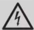
Warning for electric shock.
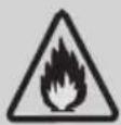
Warning for danger of fire.
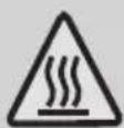
Warning for hot surfaces.
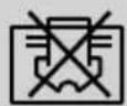
Do not cover it.

This product has been produced in environmentally friendly, modern facilities
Contents
1 Warning 6
2 Safety precautions 7
3 Notices for use 16
3.1 The conditions of unit can't normally run.... 16
3.2 Notes for heating 16
3.3 Notes for turning off 16
3.4 Emergency operation....17
3.5 Airflow direction adjustment .....17
3.6 Specific caution....18
4 Names of each part 19
4.1 Indoor unit 19
4.2 Outdoor unit 19
5 Clean and care 20
5.1 Clean the panel 20
5.2 Clean the air filter 20
5.3 Clean the air filter 21
5.4 Check before use 21
5.5 Maintain after use 21
6 Troubleshooting 22
7 Notices for installation 25
7.1 Unpacking Inspection....25
7.2 Safety Principles for Installing Air Conditioner 25
7.3 Requirements for installation position....26
7.4 Installation environment inspection 26
7.5 Requirements of the mounting structure....26
7.6 Electrical safety requirements 27
7.7 Requirements for operations at raised height 28
7.8 Grounding requirements....28
7.9 Others....28
7.10 Packing list....28
8 Install indoor unit 29
8.1 Dimension drawing of indoor unit installation 29
8.2 Mounting plate....29
8.3 Wall-through hole 29
8.4 Route of pipeline....30
8.5 Drain pipe connection....30
8.6 Wrap the piping 31
8.7 Fixing the indoor unit 32
8.8 Wiring diagram....32
9 Install outdoor unit 34
9.1 Dimension drawing of outdoor unit installation 34
9.2 Install the connection pipe....35
9.3 Wiring Connection 36
9.4 Wiring diagram....36
9.5 Vacuuming 37
9.6 Outdoor condensation drainage (Heat pump type only) 38
10 Check after installation and test operation 39
10.1 Check after installation 39
10.2 Test operation 39
11 Maintenance Notice 41
11.1 Qualification requirements of maintenance personnel 41
11.2 Inspection of the Site 41
11.3 Operating Procedures....41
11.4 Inspection of Cable 43
11.5 Leakage check of R32 refrigerant 43
11.6 Removal and Vacuum Pumping 43
11.7 Procedures of Charging Refrigerants 44
11.8 Scrap and Recovery 44
12 F-Gas instruction 47
13 Specifications 48
1 Warning

Warning:
This air conditioner uses R32 flammable refrigerant.

Note:
Air conditioner with R32 refrigerant, if roughly treated, may cause serious harm to the human body or surrounding things.
- The room space for the installation, use, repair, and storage of this air conditioner should be greater than 5m^2 .
• Air conditioner refrigerant can not charge more than 1.7kg. - Do not use any methods to speed up defrost or to clean frosty parts except for particular recommended by manufacturer.
- Not pierce or burn air conditioner, and check the refrigerant pipeline whether be damaged.
- The air conditioner should be stored in a room without lasting fire source, for example, open flame, burning gas appliance, working electric heater and so on.
- Notice that the refrigerant may be tasteless.
- The storage of air conditioner should be able to prevent mechanical damage caused by accident.
- Maintenance or repair of air conditioners using R32 refrigerant must be carried out after security check to minimize risk of incidents.
• Air conditioner must be installed with stop valve cover. - Please read the instruction carefully before installing, using and maintaining.
| Symbol | Note | Explanation |
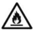 | WARNING | This symbol shows that this appliance uses a flammable refrigerant. If the refrigerant is leaked and exposed to an external ignition source, there is a risk of fire. |
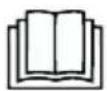 | CAUTION | This symbol shows that the operation manual should be read carefully. |
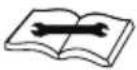 | CAUTION | This symbol shows that a service personnel should be handling this equipment with reference to the installation manual. |
 | CAUTION | This symbol shows that information is available such as the operating manual or installation manual. |
2 Safety precautions
Incorrect installation or operation by not following these instructions may cause harm or damage to people, properties, etc.
Warning
- This appliance can be used by children aged from 8 years and above and persons with reduced physical, sensory or mental capabilities or lack of experience and knowledge if they have been given supervision or instruction concerning use of the appliance in a safe way and understand the hazards involved. Children shall not play with the appliance. Cleaning and user maintenance shall not be made by children without supervision. (Only for the AC with CE-Marking)
- This appliance is not intended for use by persons (including children) with reduced physical, sensory or mental capabilities, or lack of experience and knowledge, unless they have been given supervision or instruction concerning use of the appliance by a person responsible for their safety. Children should be supervised to ensure that they do not play with the appliance. (Except for the AC with CE-Marking)
2 Safety precautions
The air conditioner must be grounded. Incomplete grounding may result in electric shocks. Do not connect the earth wire to the gas pipeline, water pipeline, lightning rod, or telephone earth wire. Do not connect the earth wire to the gas pipeline, water pipeline, lightning rod, or telephone earth wire. | Always switch off the device and cut the power supply when the unit is not in use for long time so as to ensure safety.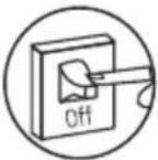 |
Take care not let the remote control and the indoor unit watered or being too wet.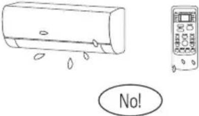 Otherwise, it may cause short circuit. Otherwise, it may cause short circuit. | If the power supply cable is damaged, it must be replaced by the manufacture or its service agent or a similar qualified person.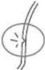 |
2 Safety precautions
| Don't cut off main power switch during operating or with wet hands. | Don't share the socket with other electric appliance. |
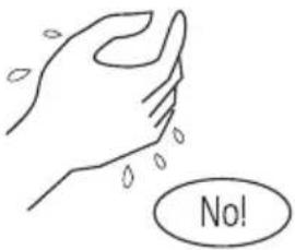 |  |
| It may cause electric shock. | Otherwise, it may cause electric shock even fire and explosion. |
| Always switch off the device and cut the power supply before performing any maintenance or cleaning. | Don't pull the power cable. |
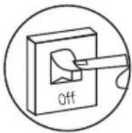 | 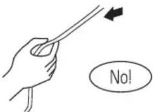 |
| Otherwise, it may cause electric shock or damage. | The damage of pulling power cord will cause serious electric shock. |
2 Safety precautions
| A warning that ducts connected to an appliance shall not contain an ignition source. | Don’t install air conditioner in a place where there is flammable gas or liquid. The distance between them should above 1 m.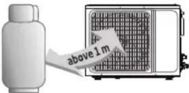 It may cause fire. It may cause fire. |
Don’t use liquid or corrosive cleaning agent wipe the air conditioner and sprinkle water or other liquid either.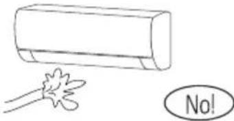 Doing this may case electric shock or damage to the unit. Doing this may case electric shock or damage to the unit. | Don’t attempt to repair the air conditioner by yourself.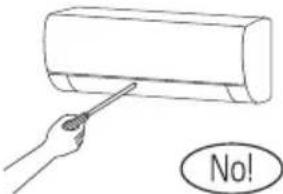 Incorrect repairs may cause electric or fire. Contact a qualified service technician for all service requirement. Incorrect repairs may cause electric or fire. Contact a qualified service technician for all service requirement. |
2 Safety precautions
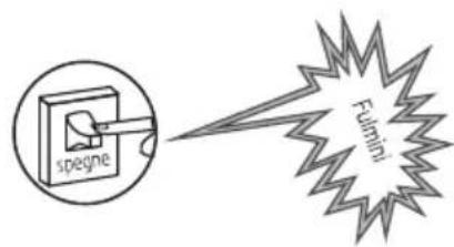
Don't use air conditioner in lightning strom weather.
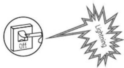
Power supply should be cut in time to prevent the occurrence of danger.
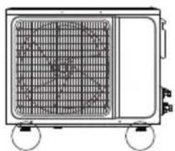
Please note whether the installed stand is firm enough or not.
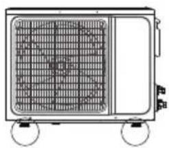
natural_image
Line drawing of a portable air conditioner unit with grid and wheels (no text or symbols)If it is damaged, it may lead to the fall of the unit and cause the injury.
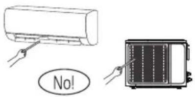
Don't put hands or any objects into the air inlets or outlets.
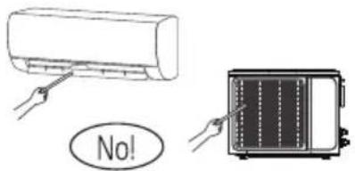
This may cause personal injury or damage to the unit.
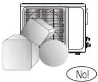
Don't block air inlet or air outlet.
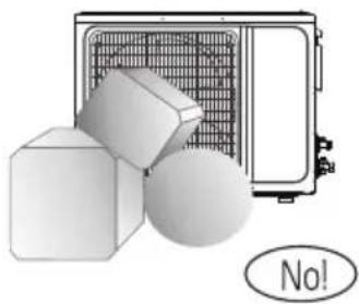
natural_image
Illustration of a kitchen appliance with a grater, cubes, and a sphere (no text or symbols)Otherwise, the cooling or heating capacity will be weakened, even cause system stop operating.
2 Safety precautions
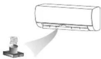
Don't let the air conditioner blow against the heater appliance.
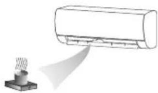
natural_image
Illustration of a steam fan emitting a cylindrical air conditioner (no text or symbols)Otherwise it will lead to incomplete combustion, thus causing poisoning.
An earth leakage breaker with rated capacity must be installed to avoid possible electric shocks.
The appliance shall be installed in accordance with national wiring regulations.
- This product contains fluorinated greenhouse gases.
- Refrigerant leakage contributes to climate change. Refrigerant with lower global warming potential (GWP) would contribute less to global warming than a refrigerant with higher GWP, if leaked to the atmosphere. This appliance contains a refrigerant fluid with a GWP equal to [675]. This means that if 1 kg of this refrigerant fluid would be leaked to the atmosphere, the impact on global warming would be [675] times higher than 1 kg of CO2, over a period of 100 years. Never try to interfere with the refrigerant circuit yourself or disassemble the product yourself and always ask a professional.
- Ensure no following objects under the indoor unit:
- microwaves, ovens and other hot objects.
- computers and other high electrostatic appliances.
- sockets that plug frequently.
2 Safety precautions
- The joints between indoor and outdoor unit shall not be reused, unless after re-flaring the pipe.
- The specification of the fuse are printed on the circuit board, such as: 3.15A/250V AC, etc.
WEEE Warning
Meaning of crossed out wheeled dustbin:
Do not dispose of electrical appliances as unsorted municipal waste, use separate collection facilities.
Contact your local government for information regarding the collection systems available.
If electrical appliances are disposed of in landfills or dumps, hazardous substances can leak into the groundwater and get into the food chain, damaging your health and well-being.
When replacing old appliances with new ones, the retailer is legally obligated to take back your old appliance for disposals at least free of charge.
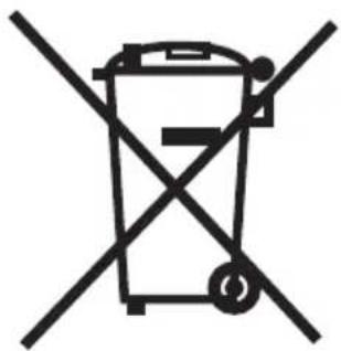
natural_image
Symbol of a trash bin crossed with no text or numbers, representing waste sorting or anti-smoking (no text present)This symbol indicates that this product shall not be disposed with other household wastes at the end of its service life. Used device must be returned to official collection point for recycling of electrical and electronic devices. To find these collection systems please contact to your local authorities or retailer where the product was purchased. Each household performs important role in recovering and recycling of old appliance. Appropriate disposal of used appliance helps prevent potential negative consequences for the environment and human health.
2 Safety precautions
Don't open the windows and doors for long time when the air conditioner is running.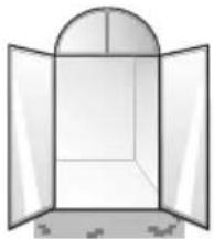 Otherwise, the cooling or heating capacity will be weakened. Otherwise, the cooling or heating capacity will be weakened. | Don't stand on the top of the outdoor unit or place heavy things on it.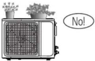 This cloud cause personal injuries or damage the unit. This cloud cause personal injuries or damage the unit. |
Don't use the air conditioner for other purposes, such as drying clothes, preserving foods, etc.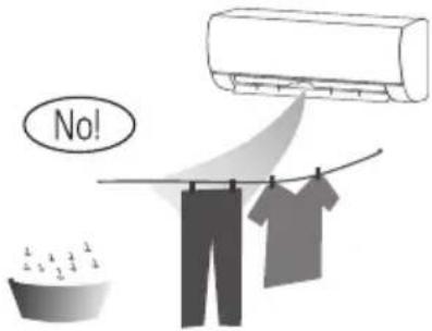 | Don't apply the cold air to the body for a long time.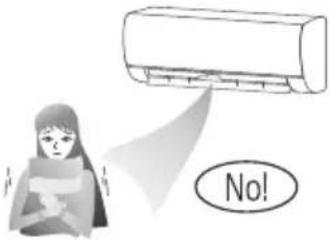 It will deteriorate your physical conditions and cause health problems. It will deteriorate your physical conditions and cause health problems. |
2 Safety precautions
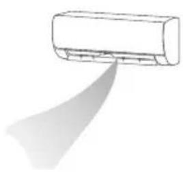
Set the suitable temperature.
natural_image
Simple line drawing of a car air conditioner with airflow direction indicated (no text or symbols)It is recommended that the temperature difference between indoor and outdoor temperature should not be too large. Appropriate adjustments of the setting temperature can prevent the waste of electricity.
If your air conditioner is not fitted with a supply cord and a plug, an all-pole switch must be installed in the fixed wiring and the distance between contacts should be no less than 3.0 mm.
- If your air conditioner is permanently connected to the fixed wiring, a anti-explosion residual current device (RCD) having rated residual operating current not exceeding 30 mA should be installed in the fixed wiring.
- The power supply circuit should have leakage protector and air switch of which the capacity should be more than 1.5 times of the maximum current.
- Regarding the installation of the air conditioners, please refer to the below paragraphs in this manual.
3 Notices for use
3.1 The conditions of unit can't normally run
- Within the temperature range provided in following table, the air conditioner may stop running and other anomalies may arise.
| Cooling | Outdoor | >43°C (Apply to T1) |
| >52°C (Apply to T3) | ||
| Indoor | <18°C | |
| Heating | Outdoor | >24°C |
| <-7°C | ||
| Indoor | >27°C |
- When the temperature is too high, the air conditioner may activate the automatic protection device, so that the air conditioner could be shut down.
- When the temperature is too low, the heat exchanger of the air conditioner may freeze, leading to water leakage or other malfunction.
- In long-term cooling or dehumidification with a relative humidity of above 80% (doors and windows are open), there may be water condenses or dripping near the air outlet.
• T1 and T3 refer to ISO 5151.
3.2 Notes for heating
- The fan of the indoor unit will not start running immediately after the heating is started to avoid blowing out cool air.
- When it is cold and wet outside, the outdoor unit will develop frost over the heat exchanger which will compromise the heating capacity. This is when the air conditioner will start defrost.
- During defrost, the air conditioner will stop heating for about 5-12 minutes.
- Vapor may come out from the outdoor unit during defrost. This is not a malfunction, but a result of fast defrost.
• Heating will resume after defrost is complete.
3.3 Notes for turning off
- When the air conditioner is turned off, the main controller will automatically decide whether to stop immediately or after running for dozens of seconds with lower frequency and lower air speed.
3 Notices for use
3.4 Emergency operation
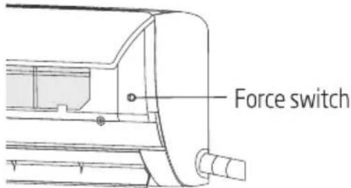
- If the remote controller is lost or broken, use force switch button to operate the air conditioner.
- If this button is pushed with the unit Off, the air conditioner will operate in Auto mode.
- If this button is pushed with the unit On, the air conditioner will stop running.
3.5 Airflow direction adjustment
- Use up-down swing and left-right swing buttons on the remote controller to adjust the airflow direction. Refer to the operation manual of the remote controller for detail.
- For models without left-right swing function, the fins has to be moved manually.
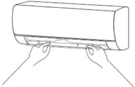
natural_image
Line drawing of two hands pressing down on a cylindrical object (no text or symbols)
Note:
Move the fins before the unit is in operation, or your finger might be injured. Never place your hand into the air inlet or outlet when the air conditioner is in operation.
3 Notices for use
3.6 Specific caution
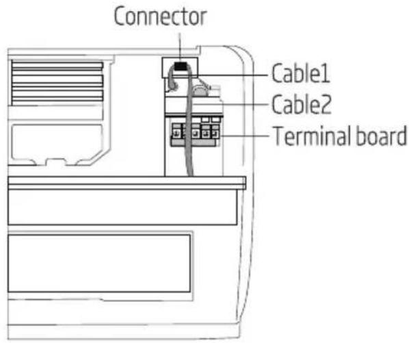
- Open front panel of the indoor.
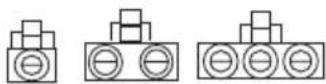
- The connector (as Fig) can not touch the terminal board, and is positioned as shown in Fig.
4 Names of each part
4.1 Indoor unit
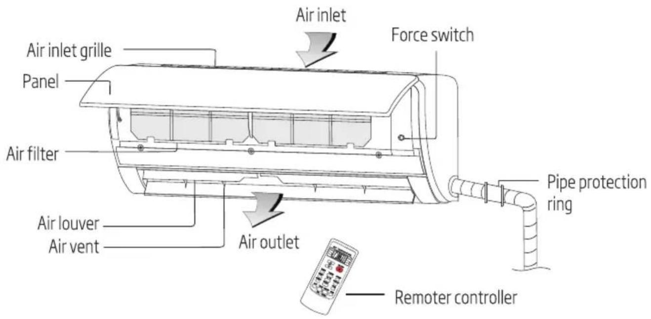
4.2 Outdoor unit
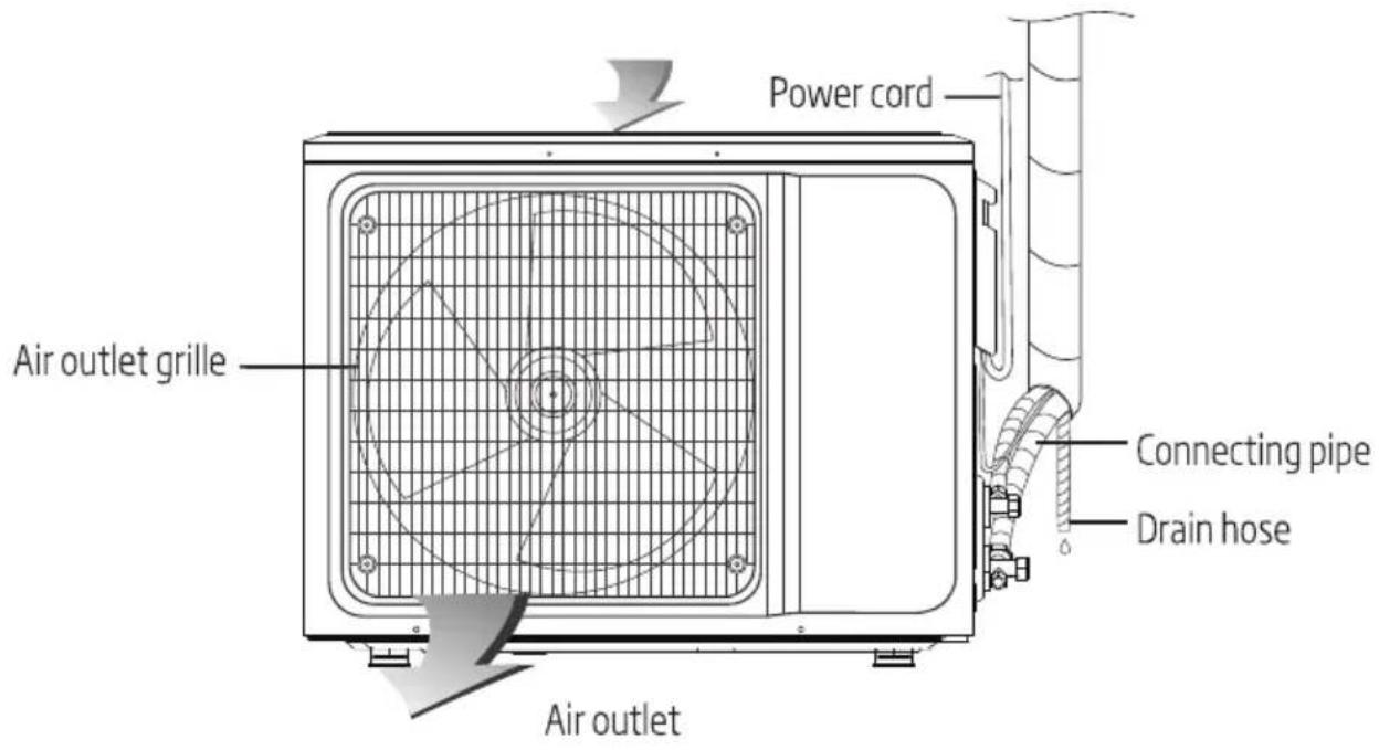

Note: All the pictures in this manual are just schematic diagrams, the actual is the standard. Plug, WIFI function, Negative-ion function, and Vertical and horizontal swing function both are optional, the actual unit shall prevail.
5 Clean and care
Warning:
- Before the cleaning of the air conditioner, it must be shut down and the electricity must be cut off for more than 5 minutes, otherwise there might be the risk of electric shocks.
- Do not wet the air conditioner, which can cause an electric shock. Make sure not to rinse the air conditioner with water under any circumstances.
- Volatile liquids such as thinner or gasoline will damage the air conditioner housing, therefore please clean the housing of air conditioner only with soft dry cloth and damp cloth moistened with neutral detergent.
- In the course of the using, pay attention to cleaning the filter regularly, to prevent the covering of dust which may affect the effect. If the service environment of the air conditioner is dusty, correspondingly increase the number of times of cleaning. After removing the filter, do not touch the fin part of the indoor unit with the finger, so as to avoid scratching it.
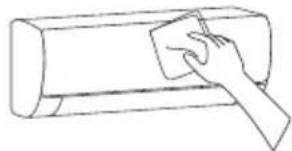
5.1 Clean the panel
When the panel of the indoor unit is contaminated, clean it gently with a wrung towel using tepid water below 45^ C, and do not remove the panel while cleaning.
natural_image
Line drawing of a hand using a power tool to clean or brush the sheet of paper (no text or symbols)5.2 Clean the air filter
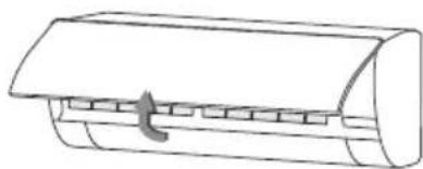
- Remove the air filter
natural_image
Line drawing of a cylindrical object with a handle and internal compartments (no text or symbols)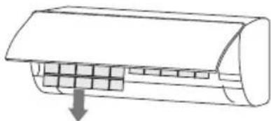
natural_image
Diagram of a car air conditioner unit with cooling fins and airflow direction arrow (no text or labels)- Use both hands to open the panel for an angle from both ends of the panel in accordance with the direction of the arrow.
- Release the air filter from the slot and remove it.
5 Clean and care
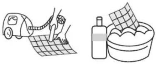
- Clean the air filter
Use a vacuum cleaner or water to rinse filter, and if the filter is very dirty (for example, with greasy dirt), clean it with warm water (below 45^ C) with mild detergent dissolved in, and then put the filter in the shade to dry in the air.
natural_image
Illustration showing a hand using a tool to clean a grid paper and wash a bowl (no text or symbols)5.3 Clean the air filter
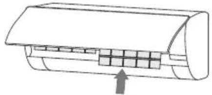
- Mount the filter
- Reinstall the dried filter in reverse order of removal, then cover and lock the panel.
natural_image
Diagram of a cylindrical air conditioner unit with internal grid structure and an upward arrow indicating airflow direction (no text or symbols)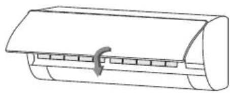
natural_image
Line drawing of a cylindrical air conditioner unit with a curved handle and internal slots (no text or symbols)5.4 Check before use
- Check whether all the air inlets and outlets of the units are unblocked.
- Check whether there is blocking in the water outlet of the drain pipe, and immediately clean it up if any.
- Check the ground wire is reliably grounded.
- Check whether the remote control batteries are installed, and whether the power is sufficient.
- Check whether there is damage in the mounting bracket of the outdoor unit, and if any, please contact our local service center.
5.5 Maintain after use
- Cut off the power source of the air conditioner, turn off the circuit breaker and remove the batteries from the remote control.
- Clean the filter and the unit body.
- Remove the dust and debris from the outdoor unit.
- Check whether there is damage in the mounting bracket of the outdoor unit, and if any, please contact our local service center.
6 Troubleshooting

Warning:
- Do not repair the air conditioner by yourself as wrong maintenance may cause electric shock or fire, please contact the authorized service center and let the professionals conduct the maintenance, and checking the following items prior to contacting for maintenance can save your time and money.
Phenomenon
The air conditioner does not work.
The air conditioner can't run after the immediate start-up after it is shut down.
The air conditioner stops running after it starts up for a while.
Troubleshooting
- There might be power outages. Wait until power is restored.
- Power plug may be loose out from the socket. The plug in the plug tightly.
- Power switch fuse may blow. Replace the fuse.
- The time for timing boot is yet to come. Wait or cancel the timer settings.
- If the air conditioner is turned on immediately after it is turned off, the protective delay switch will delay the operation for 3 to 5 minutes.
- May reach the setting temperature. It is a normal function phenomenon.
- May be at a defrosting state. It will automatically restore and run again after defrosting.
- Shutdown Timer may be set. If you continue to use, please turn it on again.
6 Troubleshooting
Phenomenon
The wind blows out, but the cooling/heating effect is not good.
Troubleshooting
- Excessive accumulation of dust on filter, blocking at air inlet and outlet, and the excessively small angle of the louver blades all will affect the cooling and heating effect. Please clean the filter, remove the obstacles at the air inlet and outlet and regulate the angle of the louver blades.
- Poor cooling and heating effect caused by doors and windows opening, and unclosed exhaust fan. Please close the doors, windows, the exhaust fan, etc.
- Auxiliary heating function is not turned on while heating, which may lead to poor heating effect. Turn on the auxiliary heating function. (only for models with auxiliary heating function)
- Mode setting is incorrect, and the temperature and wind speed settings are not appropriate. Please re-select the mode, and set the appropriate temperature and wind speed.
The indoor unit blows out odor.
There is sound of running water during the running of air conditioner.
A slight "click" sound is heard at the moment of start-up or shut-down.
- The air conditioner itself does not have undesirable odor. If there is odor, it may be due to accumulation of the odor in the environment. Clean the air filter or activate the cleaning function.
- When the air conditioner is started up or stopped, or the compressor is started up or stopped during the running, sometimes the "hissing" sound of running water can be heard. This is the sound of the flow of the refrigerant, not a malfunction.
- Due to temperature changes, panel and other parts will swell, causing the sound of friction. This is normal, not a fault.
6 Troubleshooting
Phenomenon
The indoor unit makes abnormal sound.
There are water drops over the surface of the indoor unit.
During the cooling operation, the indoor unit outlet sometimes will blow out mist.
Troubleshooting
• The sound of fan or compressor relay switched on or off.
- When the defrosting is started or stop running, it will sound. That is due to the refrigerant flowed to reverse direction. They are not malfunctions.
- Too much dust accumulation in the air filter of the indoor unit may result in fluctuation of the sound. Clean the air filters in time.
- Too much air noise when "Strong wind" is turned on. This is normal, if feeling uncomfortable, please deactivate the "Strong wind" function.
- When ambient humidity is high, water drops will be accumulated around the air outlet or the panel, etc. This is a normal physics phenomenon.
- Prolonged cooling run in open space produces water drops. Close the doors and windows.
- Too small opening angle of the louver blades may also result in water drops at the air inlet. Increase the angle of the louver blades.
- When the indoor temperature and humidity are high, it happens sometimes. This is because the indoor air is cooled rapidly. After it runs for some time, the indoor temperature and humidity will be reduced and the mist will disappear.

Warning:
Immediately stop all operations and cut off the power supply, contact our Service center locally in following situations.
- Hear any harsh sound or smell any awful odor during running.
• Abnormal heating of power cord and plug occurs. - The unit or remote controller has any impurity or water.
• Air switch or leakage protection switch is often disconnected.
7 Notices for installation

Important notices
- Before installation, please contact with local authorized maintenance center, if unit is not installed by the authorized maintenance center, the malfunction may not solve, due to discommodious contact.
- The air conditioner must be installed by professionals according to the national wiring rules and this manual.
• Refrigerant leak test must be made after installation. - To move and install air conditioner to another place, please contact our local special service center.
7.1 Unpacking Inspection
- Open the box and check air conditioner in area with good ventilation (open the door and window) and without ignition source. Note: Operators are required to wear anti-static devices.
- It is necessary to check by professional whether there is refrigerant leakage before opening the box of outdoor machine; stop installing the air conditioner if leakage is found.
- The fire prevention equipment and anti-static precautions shall be prepared well before checking. Then check the refrigerant pipeline to see if there is any collision traces, and whether the outlook is good.
7.2 Safety Principles for Installing Air Conditioner
- Fire prevention device shall be prepared before installation.
- Keep installing site ventilated.(open the door and window)
- Ignition source, smoking and calling is not allowed to exist in area where R32 refrigerant located.
- Anti-static precautions in necessary for installing air conditioner, e.g. wear pure cotton clothes and gloves.
- Keep leak detector in working state during the installation.
- If R32 refrigerant leakage occurs during the installation, you shall immediately detect the concentration in indoor environment until it reaches a safe level. If refrigerant leakage affects the performance of the air conditioner, please immediately stop the operation, and the air conditioner must be vacuumed firstly and be returned to the maintenance station for processing.
- Keep electric appliance, power switch, plug, socket, high temperature heat source and high static away from the area underneath sidelines of the indoor unit.
- The air conditioner shall be installed in an accessible location to installation and maintenance, without obstacles that may block air inlets or outlets of indoor/outdoor units, and shall keep away from heat source, inflammable or explosive conditions.
7 Notices for installation
- When installing or repairing the air conditioner and the connecting line is not long enough, the entire connecting line shall be replaced with the connecting line of the original specification; extension is not allowed.
- Use new connection pipe, unless re-flaring the pipe.
7.3 Requirements for installation position
- Avoid places of inflammable or explosive gas leakage or where there are strongly aggressive gases.
- Avoid places subject to strong artificial electric/magnetic fields.
- Avoid places subject to noise and resonance.
- Avoid severe natural conditions (e.g. heavy lampblack, strong sandy wind, direct sunshine or high temperature heat sources).
- Avoid places within the reach of children.
- Shorten the connection between the indoor and outdoor units.
- Select where it is easy to perform service and repair and where the ventilation good.
- The outdoor unit shall not be installed in any way that could occupy an aisle, stairway, exit, fire escape, catwalk or any other public area.
- The outdoor unit shall be installed as far as possible from the doors and windows of the neighbors as well as the green plants.
7.4 Installation environment inspection
- Check nameplate of outdoor unit to make sure whether the refrigerant is R32.
- Check the floor space of the room. The space shall not be less than usable space (5m2) in the specification. The outdoor unit shall be installed at a well-ventilated place.
- Check the surrounding environment of installation site: R32 shall not be installed in the enclosed reserved space of a building.
- When using electric drill to make holes in the wall, check first whether there is pre-buried pipeline for water, electricity and gas. It is suggested to use the reserved hole in the roof of the wall.
7.5 Requirements of the mounting structure
- The mounting rack must meet the relevant national or industrial standards in terms of strength with welding and connection areas rustproofed.
- The mounting rack and its load carry surface shall be able to withstand 4 times or above the weight of the unit, or 200kg , whichever is heavier.
- The mounting rack of the outdoor unit shall be fastened with expansion bolt.
7 Notices for installation
- Ensure the secure installation regardless of what type of wall on which it is installed, to prevent potential dropping that could hurt people.
7.6 Electrical safety requirements
- Be sure to use the rated voltage and air conditioners dedicated circuit for the power supply, and the power cord diameter must meet the national requirements.
- When the maximum current of air conditioner is ≥ 16A , it must use the air switch or leakage protection switch equipped with protection devices.
• The normal operating range is 90%-110% of the local rated voltage. - The minimum clearance between the air conditioner and the combustibles is 1.5 m.
- The interconnection cord connect the indoor and outdoor units. You must first choose the right cable size before preparing it for connection.
- Cable types: Outdoor power cord: H07RN-F or H05RN-F; Power cable: H07RN-F or H05RN-F;
• Minimum cross-sectional area of power and power cables
North america
| Appliance amps(A) | AWG |
| 10 | 18 |
| 13 | 16 |
| 18 | 14 |
| 25 | 12 |
| 30 | 10 |
| 40 | 8 |
Other regions
| Rated current of appliance(A) | Nominal cross-sectional area (mm2) |
| >3 and ≤ 6 | 0.75 |
| >6 and ≤ 10 | 1 |
| >10 and ≤ 16 | 1.5 |
| >16 and ≤ 25 | 2.5 |
| >25 and ≤ 32 | 4 |
| >32 and ≤ 40 | 6 |
- The size of the interconnection cord, power cable, fuse, and switch needed is determined by the maximum current of the unit. The maximum current is indicated on the nameplate located on the side panel of the unit. Refer to this nameplate to choose the right cable, fuse, or switch.

Note: Core number of cable refer to the detailed wiring diagram adhered on the unit which you purchased.
7 Notices for installation
7.7 Requirements for operations at raised height
- When carrying out installation at 2m or higher above the base level, safety belts must be worn and ropes of sufficient strength be securely fasten to the outdoor unit, to prevent falling that could cause personal injury or death as well as property loss.
7.8 Grounding requirements
- The air conditioner is the type I electrical appliance and must ensure a reliable grounding.
- Do not connect the grounding wire to a gas pipe, water pipe, lightning rod, telephone line, or a circuit poorly grounded to the earth.
- The grounding wire is specially designed and shall not be used for other purpose, nor shall it be fastened with a common tapping screw.
- Interconnection cord diameter should be recommended as per instruction manua, and with type 0 terminal that meet local standards (internal diameter of type 0 terminal needs to match the screw size of the unit, no more than 4.2mm ). After installation, check the screws whether have been fixed effectively, and there is no risk of loosening.
7.9 Others
- The connection method of the air conditioner and the power cord and the interconnection method of each independent element shall be subject to the wiring diagram affixed to the machine.
- The model and rating value of the fuse shall be subject to the silkscreen on corresponding controller or fuse sleeve.
7.10 Packing list
Packing list of the indoor unit
| Name | Quantity | Unit |
| Indoor Unit | 1 | Set |
| Remote Controller | 1 | PC |
| Batteries (7#) | 2 | PC |
| Instructions | 1 | Set |
| Drain pipe | 1 | PC |
Packing list of the outdoor unit
| Name | Quantity | Unit |
| Outdoor Unit | 1 | Set |
| Connecting pipe | 2 | PC |
| Plastic Strap | 1 | ROLL |
| Pipe Protection Ring | 1 | PC |
| Luting (putty) | 1 | PACKET |

Note: All accessories shall be subject to actual packaging material, and if there is any difference, please understand.
8 Install indoor unit
8.1 Dimension drawing of indoor unit installation
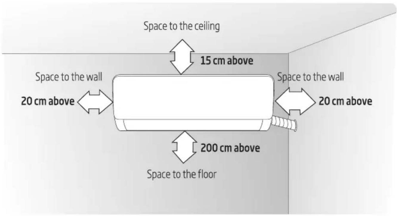
8.2 Mounting plate
- The wall for installation of the indoor unit shall be hard and firm, so as to prevent vibration.
- Use the "+" type screw to fasten the peg board, horizontally mount the peg board on the wall, and ensure the lateral horizontal and longitudinal vertical.
- Pull the peg board by hand after the installation, to confirm whether it is solid.
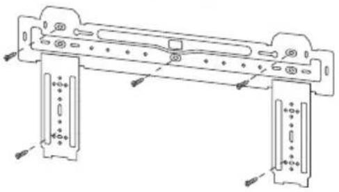
natural_image
Technical line drawing of a mechanical frame assembly with mounting holes and mounting brackets (no text or symbols)8.3 Wall-through hole
- Make a hole with an electric hammer or a water drill at the predetermined position on the wall for piping, which shall slant outwardly by 5^-10^ .
- To protect the piping and the cables from being damaged running through the wall, and from the rodents that may inhabit in the hollow wall, a pipe protecting ring shall be installed and sealed with putty.
8 Install indoor unit
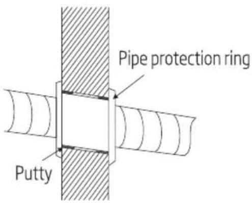

Note: Usually, the wall hole is 60mm80mm . Avoid pre-buried power wire and hard wall when making the hole.
8.4 Route of pipeline
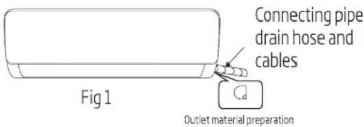
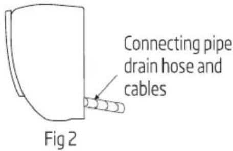
- Depending on the position of the unit, the piping may be routed sideways from the left or the right (Fig 1), or vertically from the back (Fig 2) (depending on the pipe length of the indoor unit). In the case of sideway routing, cut off the outlet cutting stock of the opposite side.
8.5 Drain pipe connection
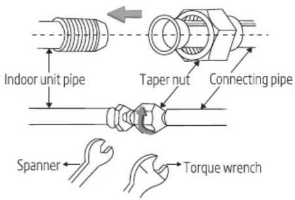
- Remove the mountings and pull the indoor unit pipe out of the housing.
- Connect the connecting pipe to the indoor unit:
Aim at the pipe center, tighten the Taper nut with fingers, and then tighten the Taper nut with a torque wrench, and the direction is shown in diagram on the right. The torque used is shown in the following table.

Note: Carefully check if there is any damage of joints before installation. The joints shall not be reused, unless after re-flaring the pipe.
8 Install indoor unit
Tightening torque table
| The size of pipe (mm) | Torque (N·m) |
| 06/06.35 | 15~25 |
| 09/09.52 | 35~40 |
| 012/012.7 | 45~60 |
| 015.88 | 73~78 |
| 019.05 | 75~80 |
8.6 Wrap the piping
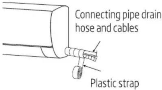
- Use the insulation sleeve to wrap the joint part the indoor unit and the connection pipe, and then use insulating material to pack and seal insulation pipe, to prevent generation of condensate water on the joint part.
- Connect the water outlet with drain pipes, and make the connection pipe, cables, and the drain hose straight.
- Use plastic cable ties to wrap the connecting pipes, cables and drain hose. Run the pipe sloping downward.
8 Install indoor unit
8.7 Fixing the indoor unit
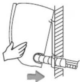
- Hang the indoor unit on the peg board, and move the unit from left to right to ensure that the hook is properly positioned in the peg board.
- Push toward the lower left side and the upper right side of the unit toward the peg board, until the hook is embedded in the slot and makes a "click" sound.
natural_image
Diagram of a hand holding a curved object with a pipe inserted, showing an arrow indicating direction (no text or symbols present)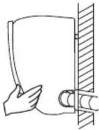
natural_image
Simple line drawing of a hand holding a cylindrical object next to a vertical wall (no text or symbols)8.8 Wiring diagram
- If your air conditioner is provided with power cable, the wiring of the indoor unit is connected in the factory, there is no need of connection.
- If the power cable is not provided, connection is needed in accordance with the wiring diagram.
After installation, check:
- The screws whether have been fixed effectively, and there is no risk of loosening.
- Connector of display board whether put in the right place and do not touch the terminal board.
- Control box cover whether cover tightly.
Constant speed
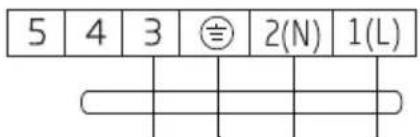
To outdoor unit
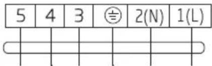
To outdoor unit
Variable speed
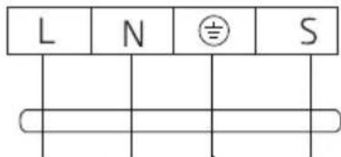
To outdoor unit
To outdoor unit
Connector
If there is a connector, connect it directly.
8 Install indoor unit
Note:
- This manual is usually includes the wiring mode for the different kind of A/C. We cannot exclude the possibility that some special types of wiring diagrams are not included.
- The diagram is for reference only. If the entity is difference with this wiring diagram, please refer to the detailed wiring diagram adhered on the unit which you purchased.
9 Install outdoor unit
9.1 Dimension drawing of outdoor unit installation
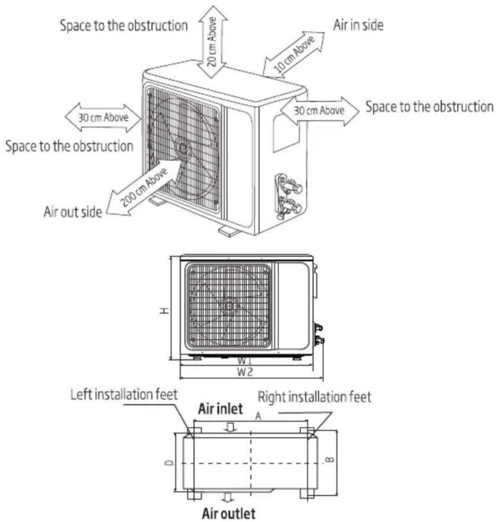
Installation outdoor unit bolt
| Outdoor unit size of shape W1 (W2) * H * D) (mm) | A (mm) | B (mm) |
| 665 (710) × 420 × 280 | 430 | 280 |
| 600 (645) × 485 × 260 | 400 | 290 |
| 660 (710) × 500 × 240 | 500 | 260 |
| 700 (745) × 500 × 255 | 460 | 260 |
| 730 (780) × 545 × 285 | 540 | 280 |
| 760 (810) × 545 × 285 | 540 | 280 |
| 790 (840) × 550 × 290 | 545 | 300 |
| 800 (860) × 545 × 315 | 545 | 315 |
| 800 (850) × 590 (690) × 310 | 540 | 325 |
9 Install outdoor unit
| 825 (880) × 655 × 310 | 540 | 335 |
| 900 (950) × 700 × 350 | 630 | 350 |
| 900 (950) × 795 × 330 | 535 | 350 |
| 970 (1044) × 803 × 395 | 675 | 409 |
9.2 Install the connection pipe
Connect the Outdoor Unit with Connecting Pipe: Aim the counter-bore of the connecting pipe at the stop valve, and tighten the Taper nut with fingers. Then tighten the Taper nut with a torque wrench.
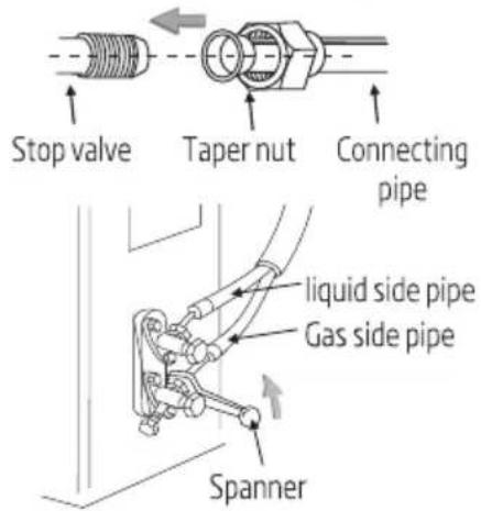
- When prolonging the piping, extra amount of refrigerant must be added so that the operation and performance of the air conditioner will not be compromised.
| Piping length | Amount of refrigerant to be added | Amount of refrigerant for the unit | |
| ≤ 5 M | Not needed | ||
| 5-15 M | CC ≤ 12000 Btu | 16 g/m | ≤ 1 kg |
| CC ≥ 18000 Btu | 24 g/m | ≤ 2 kg | |
Note:
- This table is for reference only.
- The joints shall not be reused, unless after re-flaring the pipe.
- After installation, check the stop valve cover whether be fixed effectively.
9 Install outdoor unit
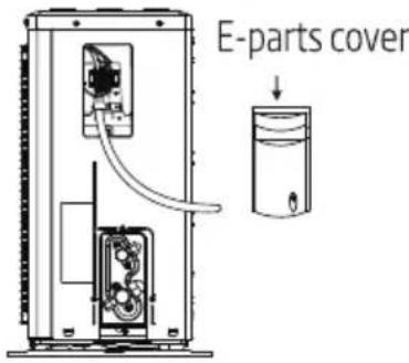
9.3 Wiring Connection
- Loosen the screws and remove E-parts cover from the unit.
- Connect the cables respectively to the corresponding terminals of the terminal board of the outdoor unit (see the wiring diagram), and if there are signals connected to the plug, just conduct butt joint.
- Ground wire: Remove the grounding screw out of the electric bracket, cover the grounding wire end onto the grounding screw and screw it into the grounding hole.
- Fix the cable reliably with fasteners (Pressing board).
- Put the E-parts cover back in its original place and fasten it with screws.
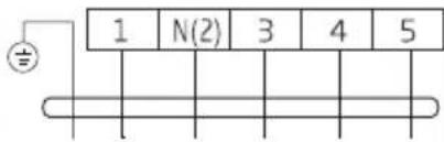
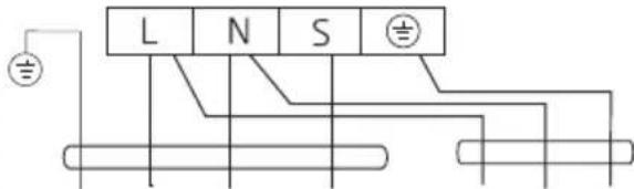
9.4 Wiring diagram
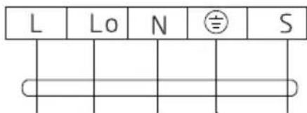
Constant speed
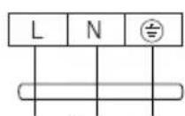
To power
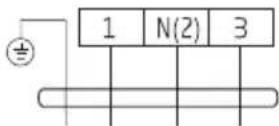
To indoor unit
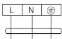
To power
To indoor unit
Variable speed
To indoor unit
To power
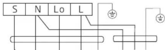
To indoor unit
To power
Connector

If there is a connector, connect it directly.
9 Install outdoor unit
Note:
This manual is usually includes the wiring mode for the different kind of A/C. We cannot exclude the possibility that some special types of wiring diagrams are not included.
The diagram is for reference only. If the entity is difference with this wiring diagram, please refer to the detailed wiring diagram adhered on the unit which you purchased.
9.5 Vacuuming
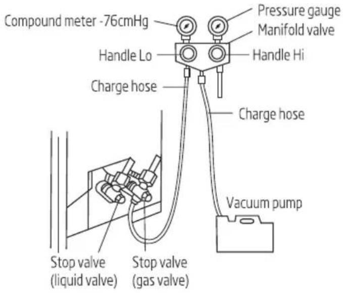
- Exclusive R32 refrigerant pump must be used in making R32 refrigerant vacuum.
Before working on the air conditioner, remove the cover of the stop valve (gas and liquid valves) and be sure to retighten it afterward. (to prevent the potential air leakage)
- To prevent air leakage and spilling tighten all connecting nut of all flare tubes.
- Connect the stop valve, charge hose, manifold valve, and vacuum pump.
- Fully open the handle Lo of the manifold valve and apply vacuum for at least 15 minutes and check that the compound vacuum gauge reads -0.1 MPa (-76 cm Hg).
- After applying vacuum, fully open the stop valve with a hex wrench.
- Check that both indoor and outdoor connections are free of air leakage.
9 Install outdoor unit
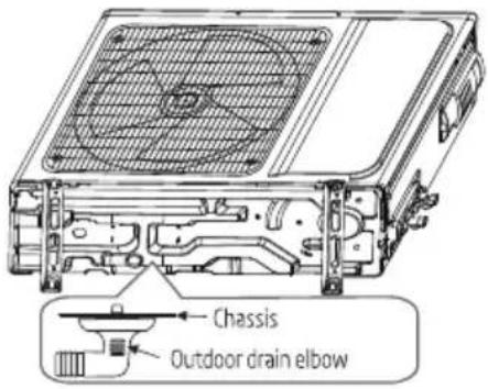
9.6 Outdoor condensation drainage (Heat pump type only)
When the unit is heating, the condensing water and defrosting water can be out reliably through the drain house.
Installation:
Install the outdoor drain elbow in ∅25 hole on the base plate, and joint the drain hose to the elbow, so that the waste water formed in the outdoor unit can be drained out to a proper plate.
10 Check after installation and test operation
10.1 Check after installation
• Electrical safety Check
- If the supply voltage is as required.
- If there is any faulty or miss connection in each of the power, signal and grounding wires.
- If the grounding wire of the air conditioner is securely grounded.
• Installation safety Check
- If the installation is secure.
- If the water drain is smooth.
- If the wiring and piping are correctly installed.
- Check that no foreign matter or tools are left inside the unit.
- Check the refrigerant pipeline is protected well.
- Leak test of the refrigerant
Depending on the installation method, the following methods may be used to check for suspect leak, on areas such as the four connections of the outdoor unit and the cores of the cut-off valves and t-valves:
- Bubble method: Apply of spray a uniform layer of soap water over the suspected leak spot and observe carefully for bubble.
- Instrument method: Checking for leak by pointing the probe of the leak detector according to the instruction to the suspect points of leak.

Note: Make sure that the ventilation is good before checking.
10.2 Test operation
Test operation preparation:
- Verify that all piping and connection cables are well connected.
- Confirm that the values at the gas side the liquid-side are fully open.
- Connect the power cord to an independent power socket.
• Install batteries in remote control.

Note: Make sure that the ventilation is good before testing.
10 Check after installation and test operation
Test operation method:
- Turn on the power and push the On/Off switch button of the remote controller to start the air conditioner.
- Select Cool, Heat (not available on cool-only models), Swing and other operation modes with the remote controller and see if the operation is ok.
11 Maintenance Notice
Note: For maintenance or scrap, please contact authorized service centers. Maintenance by unqualified person may cause dangers.
Feed air conditioner with R32 refrigerant, and maintain the air conditioner in strictly accordance with manufacturer's requirements. The chapter is mainly focused on special maintenance requirements for appliance with R32 refrigerant. Ask repairer to read after-sales technical service handbook for detailed information.
11.1 Qualification requirements of maintenance personnel
- Special training additional to usual refrigerating equipment repair procedures is required when equipment with flammable refrigerants is affected. In many countries, this training is carried out by national training organisations that are accredited to teach the relevant national competency standards that may be set in legislation. The achieved competence should be documented by a certificate.
- The maintenance and repair of the air conditioner must be conducted according to the method recommended by the manufacturer. If other professionals are needed to help maintain and repair the equipment, it should be conducted under the supervision of individuals who have the qualification to repair AC equipped with flammable refrigerant.
11.2 Inspection of the Site
Safety inspection must be taken before maintaining equipment with R32 refrigerant to make sure the risk of fire is minimized. Check whether the place is well ventilated, whether anti-static and fire prevention equipment is perfect.
While maintaining the refrigeration system, observe the following precautions before operating the system.
11.30 Operating Procedures
1. General work area:
All maintenance staff and others working in the local area shall be instructed on the nature of work being carried out. Work in confined spaces shall be avoided. The area around the workspace shall be sectioned off. Ensure that the conditions within the area have been made safe by control of flammable material.
2. Checking for presence of refrigerant:
The area shall be checked with an appropriate refrigerant detector prior to and during work, to ensure the technician is aware of potentially toxic or flammable atmospheres. Ensure that the leak detection equipment being used is suitable for use with all applicable refrigerants, i.e. non-sparking, adequately sealed or intrinsically safe.
11 Maintenance Notice
3. Presence of fire extinguisher:
If any hot work is to be conducted on the refrigeration equipment or any associated parts, appropriate fire extinguishing equipment shall be available to hand. Have a dry powder or CO2 fire extinguisher adjacent to the charging area.
4. No ignition sources:
No person carrying out work in relation to a refrigeration system which involves exposing any pipe work shall use any sources of ignition in such a manner that it may lead to the risk of fire or explosion. All possible ignition sources, including cigarette smoking, should be kept sufficiently far away from the site of installation, repairing, removing and disposal, during which refrigerant can possibly be released to the surrounding space. Prior to work taking place, the area around the equipment is to be surveyed to make sure that there are no flammable hazards or ignition risks.
'No Smoking' signs shall be displayed.
5. Ventilated Area(open the door and window):
Ensure that the area is in the open or that it is adequately ventilated before breaking into the system or conducting any hot work. A degree of ventilation shall continue during the period that the work is carried out. The ventilation should safely disperse any released refrigerant and preferably expel it externally into the atmosphere.
6. Checks to the refrigeration equipment:
Where electrical components are being changed, they shall be fit for the purpose and to the correct specification. At all times the manufacturer's maintenance and service guidelines shall be followed. If in doubt, consult the manufacturer's technical department for assistance. The following checks shall be applied to installations using flammable refrigerants:
- The charge size is in accordance with the room size within which the refrigerant containing parts are installed.
- The ventilation machinery and outlets are operating adequately and are not obstructed.
- If an indirect refrigerating circuit is being used, the secondary circuit shall be checked for the presence of refrigerant.
- Refrigeration pipe or components are installed in a position where they are unlikely to be exposed to any substance which may corrode refrigerant containing components, unless the components are constructed of materials which are inherently resistant to being corroded or are suitably protected against being so corroded.
7. Checks to electrical devices:
Repair and maintenance to electrical components shall include initial safety checks and component inspection procedures. If a fault exists that could compromise safety, then no electrical supply shall be connected to the circuit until it is satisfactorily dealt with. If the fault cannot be corrected immediately but it is necessary to continue operation, an adequate temporary solution shall be used. This shall be reported to the owner of the equipment so all parties are advised.
11 Maintenance Notice
Initial safety checks shall include:
- That capacitors are discharged: this shall be done in a safe manner to avoid possibility of sparking.
- That no live electrical components and wiring are exposed while charging, recovering or purging the system.
- Keep continuity of earthing.
11.4 Inspection of Cable
- Check the cable for wear, corrosion, overvoltage, vibration and check if there are sharp edges and other adverse effects in the surrounding environment. During the inspection, the impact of aging or the continuous vibration of the compressor and the fan on it should be taken into consideration.
11.5 Leakage check of R32 refrigerant

Note: Check the leakage of the refrigerant in an environment where there is no potential ignition source. No halogen probe (or any other detector that uses an open flame) should be used.
Leak detection method:
For systems with refrigerant R32, electronic leak detection instrument is available to detect and leak detection should not be conducted in environment with refrigerant. Make sure the leak detector will not become a potential source of ignition, and is applicable to the measured refrigerant. Leak detector shall be set for the minimum ignitable fuel concentration (percentage) of the refrigerant. Calibrate and adjust to proper gas concentration (no more than 25%) with the used refrigerant.
The fluid used in leak detection is applicable to most refrigerants. But do not use chloride solvents to prevent the reaction between chlorine and refrigerants and the corrosion of copper pipeline.
If you suspect a leak, then remove all the fire from the scene or put out the fire.
If the location of the leak needs to be welded, then all refrigerants need to be recovered, or, isolate all refrigerants away from the leak site (using cut-off valve). Before and during the welding, use OFN to purify the entire system.
11.6 Removal and Vacuum Pumping
- Make sure there is no ignited fire source near the outlet of the vacuum pump and the ventilation is well.
- Allow the maintenance and other operations of the refrigeration circuit should be carried out according to the general procedure, but the following best operations that the flammability is already taken into consideration are the key. You should follow the following procedures:
- Remove the refrigerant.
11 Maintenance Notice
- Decontaminate the pipeline by inert gases.
• Evacuation. - Decontaminate the pipeline by inert gases again.
-
Cut or weld the pipeline.
-
The refrigerant should be returned to the appropriate storage tank. The system should be blown with oxygen free nitrogen to ensure safety. This process may need to be repeated for several times. This operation shall not be carried out using compressed air or oxygen.
-
Through blowing process, the system is charged into the anaerobic nitrogen to reach the working pressure under the vacuum state, then the oxygen free nitrogen is emitted to the atmosphere, and in the end, vacuumize the system. Repeat this process until all refrigerants in the system is cleared. After the final charging of the anaerobic nitrogen, discharge the gas into the atmosphere pressure, and then the system can be welded. This operation is necessary for welding the pipeline.
11.7 Procedures of Charging Refrigerants
As a supplement to the general procedure, the following requirements need to be added:
- Make sure that there is no contamination among different refrigerants when using a refrigerant charging device. The pipeline for charging refrigerants should be as short as possible to reduce the residual of refrigerants in it.
- Storage tanks should remain vertically up.
- Make sure the grounding solutions are already taken before the refrigeration system is charged with refrigerants.
- After finishing the charging (or when it is not yet finished), label the mark on the system.
- Be careful not to overcharge refrigerants.
11.8 Scrap and Recovery
Scrap:
Before this procedure, the technical personnel shall be thoroughly familiar with the equipment and all its features, and make a recommended practice for refrigerant safe recovery. For recycling the refrigerant, shall analyze the refrigerant and oil samples before operation. Ensure the required power before the test.
- Be familiar with the equipment and operation.
- Disconnect power supply.
- Before carrying out this process, you have to make sure:
- If necessary, mechanical equipment operation should facilitate the operation of the refrigerant tank.
- All personal protective equipment is effective and can be used correctly.
- The whole recovery process should be carried out under the guidance of qualified personnel.
11 Maintenance Notice
• The recovering of equipment and storage tank should comply with the relevant national standards.
4. If possible, the refrigerating system should be vacuumized.
5. If the vacuum state can't be reached, you should extract the refrigerant in each part of the system from many places.
6. Before the start of the recovery, you should ensure that the capacity of the storage tank is sufficient.
7. Start and operate the recovery equipment according to the manufacturer's instructions.
8. Don't fill the tank to its full capacity (the liquid injection volume does not exceed 80% of the tank volume).
9. Even the duration is short, it must not exceed the maximum working pressure of the tank.
10. After the completion of the tank filling and the end of the operation process, you should make sure that the tanks and equipment should be removed quickly and all closing valves in the equipment are closed.
11. The recovered refrigerants are not allowed to be injected into another system before being purified and tested.
Note: The identification should be made after the appliance is scrapped and refrigerants are evacuated. The identification should contain the date and endorsement. Make sure the identification on the appliance can reflect the flammable refrigerants contained in this appliance.
Recovery:
- The clearance of refrigerants in the system is required when repairing or scrapping the appliance. It is recommended to completely remove the refrigerant.
- Only a special refrigerant tank can be used when loading the refrigerant into the storage tank. Make sure the capacity of the tank is appropriate to the refrigerant injection quantity in the entire system. All tanks intended to be used for the recovery of refrigerants should have a refrigerant identification (i.e. refrigerant recovery tank). Storage tanks should be equipped with pressure relief valves and globe valves and they should be in a good condition. If possible, empty tanks should be evacuated and maintained at room temperature before use.
- The recovery equipment should be kept in a good working condition and equipped with equipment operating instructions for easy access. The equipment should be suitable for the recovery of R32 refrigerants. Besides, there should be a qualified weighting apparatus which can be normally used. The hose should be linked with detachable connection joint of zero leakage rate and be kept in a good condition. Before using the recovery equipment, check if it is in a good condition and if it gets perfect maintenance. Check if II electrical components are sealed to prevent the leakage of the refrigerant and the fire caused by it. If you have any question, please consult the manufacturer.
11 Maintenance Notice
- The recovered refrigerant shall be loaded in the appropriate storage tanks, attached with a transporting instruction, and returned to the refrigerant manufacturer. Don't mix refrigerant in recovery equipment, especially a storage tank.
- The space loading R32 refrigeration can't be enclosed in the process of transportation. Take anti electrostatic measures if necessary in transportation. In the process of transport, loading and unloading, necessary protective measures must be taken to protect the air conditioner to ensure that the air conditioner is not damaged.
- When removing the compressor or clearing the compressor oil, make sure the compressor is pumped to an appropriate level to ensure that there is no residual R32 refrigerants in the lubricating oil. The vacuum pumping should be carried out before the compressor is returned to the supplier. Ensure the safety when discharging oil from the system. Installation instructions
12 F-Gas instruction
This product contains fluorinated greenhouse gases covered by the Kyoto protocol.
The fluorinated greenhouse gases are contained in hermetically sealed equipment.
Installs, services, maintains, repairs, checks for leaks or decommissions equipment and product recycling should be carried out by natural persons that hold relevant certificates.
If the system has a leakage detection system installed, leakage checks should be performed at least every 12 months, make sure system operate properly.
If product must be performed leakage checks, it should specify Inspection cycle, establish and save records of leakage checks.

Note: For hermetically sealed equipment, portable air conditioner, window air conditioner and dehumidifier, if CO_2 equivalent of fluorinated greenhouse gases is less than 10 tonnes, it should not perform leakage checks.
13 Specifications
| Beko Model Name | BIVPA 090/ BIVPA 091 | BIVPA 120/ BIVPA 121 | BIVPA 180/ BIVPA 181 | BIVPA 240/ BIVPA 241 |
| Refrigerant type | R32 | R32 | R32 | R32 |
| Total Refrigerant Amount (g) | 580 | 680 | 1280 | 1440 |
| CO2 equivalent (Tonnes) | 0.392 | 0.459 | 0.864 | 0.972 |
| Climate Class | T1 | T1 | T1 | T1 |
| Heating Type | Heat Pump | Heat Pump | Heat Pump | Heat Pump |
| Power Supply Connection | Outdoor | Outdoor | Outdoor | Outdoor |
| Cooling Capacity (Btu/h) (PdesignC) | 8189 | 11942 | 18084 | 22860 |
| Adjustable Cooling Capacity Range (Btu/h) | 2730-8872 | 3140-12283 | 4435-18425 | 6825-25930 |
| Cooling Capacity (W) (PdesignC) | 2400 | 3500 | 5300 | 6700 |
| Adjustable Cooling Capacity Range (W) | 800-2600 | 1000-3600 | 1300-5400 | 2000-7600 |
| Heating Capacity (Btu/h) (Pdeisgn H) | 8872 | 9212 | 15013 | 19448 |
| Adjustable Heating Capacity Range (Btu/h) | 2730-9215 | 4095-11953 | 4776-20813 | 8530-27296 |
| Heating Capacity (W) (Pdeisgn H) | 2600 | 2700 | 4400 | 5700 |
| Adjustable Heating Capacity Range (W) | 800-2700 | 1200-3500 | 1400-4730 | 2500-8000 |
| SEER (EU) (W/W) | 6.1 | 6.1 | 6.1 | 6.1 |
| SCOP (EU Average Season) (W/W) | 4.0 | 4.0 | 4.0 | 4.0 |
| Energy Level-Cooling (EU) | A++ | A++ | A++ | A++ |
| Energy Level-Heating (EU Average Season) | A+ | A+ | A+ | A+ |
13 Specifications
| Cooling Power Input (W) | 800 | 1090 | 1650 | 2200 |
| Heating Power Input (W) | 750 | 970 | 1490 | 1960 |
| Voltage/Frequency (V/Hz) | 220-240V~ 50Hz, 1Ph | 220-240V~ 50Hz, 1Ph | 220-240V~ 50Hz, 1Ph | 220-240V~ 50Hz, 1Ph |
| Noise Power Level - Indoor Unit (dBA) (Sound Power) | 53 | 52 | 57 | 60 |
| Noise Power Level - Outdoor Unit (dBA) (Sound Power) | 57 | 58 | 61 | 64 |
| Noise Pressure Level - Indoor Unit (dBA) (Sound Pressure) | 42/35/31 | 42/36/31 | 46/42/37 | 49/43/38 |
| Noise Pressure Level - Outdoor Unit (dBA) (Sound Pressure) | 52 | 52 | 54 | 55 |
| Air flow volume (m3/h) | 600/500/450 | 600/500/450 | 850/800/750 | 1150/1100/1040 |
| Moisture removal (L/H.r) | 0.9 | 1.2 | 1.75 | 2.5 |
| Max. elevation (m) | 10 | 10 | 15 | 15 |
| Max. pipe length (m) | 20 | 20 | 25 | 25 |
| Ambient Working Temperature Range(°C) Cooling-Outdoor | 16°C ~ 48°C | 16°C ~ 48°C | 16°C ~ 48°C | 16°C ~ 48°C |
| Ambient Working Temperature Range(°C) Heating-Outdoor | -10°C ~ 30°C | -10°C ~ 30°C | -10°C ~ 30°C | -10°C ~ 30°C |
-
Specification are standard values calculate based on rated operation conditions. They will vary in difference work condition.
-
Our company has quick technical improvements. There will be no prior notice for any change of technical data. Please read nameplate on the air-conditioner.
-
Rated value is tested under 35/24(In.)35/24(Out).
-
CO2 equivalent (Tonnes)
| Importer in PolandImporter W PolsceBeko S.A.ul. Puławska 36602-819 Warszawawww.beko.pl | Importer in Czech RepublicDovozce do České republikyBEKO S.A., organizační složkaBucharova 1423/6,Praha 13 - Nové Butovice, 158 00www.bekocr.cz | Importer in SlovakiaDovozca na SlovenskoBEKO Slovakia s.r.o.Suché mýto 1811 03 Bratislavawww.bekosk.sk | Importer in EstoniaImportija EestiBeko S.A.Tānav Puławska 36602-819 Varssavi (Poola) | |||
| Importer in GermanyBeko Deutschland GmbHThomas-Edison-Platz 363263 Neu-Isenburg | Importer in UKBEKO Plc, Beko House,1 Greenhill Crescent,Watford, Herts,WD18 8QU | KSA ImporterAL BABTAIN TRADING CO.P.O. Box # 181,Riyadh 11411-KSA+966-11-4744788 | Importer in FranceBEKO France / ImmeubleStadium,266 Avenue duPrésident Wilson,93210,St-Denis La Plaine Cedex | |||
| Importer in SpainBEKO ELECTRONICSESPANA S.L.C/ Provenza388 1° Piso / 08025Barcelona | Importer for MaltaETV LTD119/120Archbishop StreetVALLETTA MALTA | Importer in LatviaImportētāja LatvijāBeko S.A.Ielas Puławska 36602-819 Varšava (Polija) | Importer in LithuaniaImportuotojas LietuvojeBeko S.A.Gatvė Puławska 36602-819 Varšuva (Lenkija) | |||
| Importer in AustriaELEKTRA BREGENZ AGPFARRGASSE 77VIENNA post code 1230 | Importer in SwitzerlandGrundig Nordic ABIsafjordsgatan 39B 16440Kista SWEDEN | Importer in HungaryHauser Magyarorszag imitedBaross utca 89 PC: 2040Budaōrs / Hungary | Importer in SloveniaBIG BANG, D.O.O.Šmartinska cesta 152PC: 1000Ljubljana/Slovenia | Importer in ItalyBEKO ITALY SRLViale Del Ghisallo,20/I-20151 Milano (MI) | ||
| Importer in RomaniaARCTIC S.A.Str. 13 Decembrie, nr.210Gäeşti, 135200, Româniawww.arctic.ro | Importer in BeneluxSchaliënhoevedreefB - 2800Mechelen - Belgium | Importer in GreecePAR. SEITANIDIS S.A.Polistilo, P.O. Box:1402Kavala, 64003 | Importer in BulgariaVideolux LTD /PO Box 2109 /2109 Sofia | Importer in CroatiaE PLUS doo ZA Unutamju /GOSPODARSKA 16c /10225 GORNJISTUPNIK / ZAGREP | ||
| Importer in Russia Импортер на территории РФ: ООО «БЕКО», 601021, Россия, Владимирская область,Киржачский район, деревня Федоровское, улица Сельская, 49Бесплатная линия сервисного обслуживания и информационной поддержки по установке и эксплуатации (только длязвонков по России) 8-800-200-23-56Изготовитель: Arcelik A.Ş. Турция, Karaagac caddesi No: 2-6 Istanbul 34445 Sutluce, Istanbul | ||||||
| Виробник: «Arçelik A.Ş» Karaağaç Caddesi No: 2-6, Sütlüce, 34445 İstanbul, Turkey, «Arçelik A.Ş», м. Стамбул,Сютлюдже, вул. Караагач No 2-6, 34445, ТуреччинаІмпортер на території України:ТОВ «Беко Україна», адреса: 03150, м. Київ, вул. Антоновича, буд. 72, тел/факс.: 0-800-500-4-3-2 Термін служби 3 роки | ||||||
| Manufactured by Arcelik A.S. Karaagac Cd. No:2-6 34445 Sutluce, Beyoglu, Istanbul, Turkey 19/10 Rev: 01 | ||||||
Leggere prima il presente manuale!
Gentile Cliente,
grazie per aver scelto un prodotto Beko. Ci auguriamo che lei ottenga i migliori risultati dal suo prodotto, realizzato secondo elevati standard di qualità e con una tecnologia all'avanguardia. Pertanto, prima di utilizzare il prodotto, legga attentamente tutto il manuale e tutti i documenti di accompagnamento e li conservi per riferimento futuro. Se cede il prodotto a qualcun altro, gli fornisca anche il manuale dell'utente. Segua tutte le avvertenze e le informazioni riportate nel manuale dell'utente.
Significato dei simboli
I seguenti simboli sono utilizzati in diverse sezioni di questo manuale:

Informazioni importanti o suggerimenti pratici sull'utilizzo.
Avvertenza:situazioni di pericolo relative a vita e proprietà.

Avvertenza: operazioni da non eseguire.
Attenzione alle scosse elettriche.
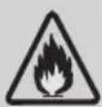
Attenzione al pericolo di incendi.
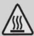
Attenzione alle superfici calde.
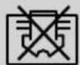
Non coprirlo.

Il presente prodotto è stato realizzato in strutture ecosostenibili e moderne
Sommario
1 Attenzione 55
2 Misure di sicurezza 56
3 Note per l'uso 65
3.1 Condizioni in cui l'unità normalmente non funziona 65
3.2 Note per il riscaldamento 65
3.3 Note per lo spegnimento 65
3.4 Funzionamento di emergenza....66
3.5 Regolazione della direzione del flusso d'aria....66
3.6 Cautela specifica 67
4 Nomi di ciascuna parte 68
4.1 Unità interna....68
4.2 Unità esterna 68
5 Pulizia e cura 69
5.1 Pulizia del pannello....69
5.2 Pulire il filtro dell'aria....69
5.3 Pulire il filtro dell'aria....70
5.4 Controlli prima dell'uso 70
5.5 Manutenzione dopo l'uso 70
6 Risoluzione dei problemi 71
7 Note relative all'installazione 74
7.1 Disimballaggio Ispezione....74
7.2 Principi di sicurezza per l'installazione del condizionatore....74
7.3 Requisiti per la posizione di installazione.... 75
7.4 Ispezione dell'ambiente di installazione 75
7.5 Requisiti della struttura di montaggio 75
7.6 Requisiti di sicurezza elettrica 76
7.7 Requisiti per le operazioni in altezza sollevata 77
7.8 Requisiti di messa a terra 77
7.9 Altro....77
7.10 Contenuto della confezione 77
8 Installare l'unità interna 78
8.1 Disegno quotato dell'installazione dell'unità interna 78
8.2 Piastra di montaggio....78
8.3 Foro passante....78
8.4 Percorso delle tubazioni 79
8.5 Collegamento del tubo di scarico 79
8.6 Avvolgimento delle tubazioni....80
8.7 Fissaggio dell'unità interna 81
8.8 Schema di cablaggio 81
9 Installare l'unità esterna 83
9.1 Disegno quotato dell'installazione dell'unità esterna....83
9.2 Installazione del tubo di collegamento....84
9.3 Connessione dei cavi....85
9.4 Schema di cablaggio 85
9.5 Aspirazione 86
9.6 Scarico condensa esterno (solo modello con pompa di calore) 87
10 Controllare dopo l'installazione e il funzionamento di prova 88
10.1 Controlli dopo l'installazione 88
10.2 Prova di funzionamento 88
11 Avviso relativo alla manutenzione 90
11.1 Requisiti di qualifica del personale di manutenzione 90
11.2 Ispezione del sito 90
11.3 Procedure operative 90
11.4 Ispezione del cavo....92
11.5 Controllo di perdita del refrigerante R32 92
11.6 Rimozione e pompaggio a vuoto....93
11.7 Procedure di ricarica dei refrigeranti....93
11.8 Rottamare e recuperare 94
12 Istruzioni per l'installazione 96
12.1 F-Gas - Istruzioni 96
13 Specifiche 97
1 Attenzione

Avvertenza:
Questo condizionatore usa un refrigerante infiammabile R32.

Nota:
Il condizionatore con refrigerante R32, se trattato in modo approssimativo, può causare gravi danni al corpo umano o alle cose circostanti.
- Lo spazio nell'ambiente per l'installazione, l'uso, la riparazione e la conservazione di questo condizionatore deve essere superiore a 5 m ^2 .
- Il refrigerante del condizionatore non può caricare più di 1,7 kg.
- Non utilizzare alcun metodo per accelerare lo sbrinamento o per pulire le parti gelate fatta eccezione per quanto consigliato dal produttore.
- Non forare o bruciare il condizionatore e controllare se la tubazione del refrigerante è danneggiata.
- Il condizionatore deve essere conservato in una stanza senza fonte di fuoco permanente, ad esempio, fiamme libere, apparecchi a gas acceso, riscaldamento elettrico funzionante e così via.
- Si noti che il refrigerante potrebbe essere insapore
- La conservazione del condizionatore dovrebbe essere in grado di prevenire danni meccanici causati da incidenti.
- La manutenzione o la riparazione dei condizionatori che usano refrigerante R32 deve essere eseguita dopo il controllo di sicurezza per ridurre al minimo il rischio di incidenti.
- Il condizionatore deve essere installato con il coperchio della valvola di arresto.
- Leggere attentamente le istruzioni prima di installare, utilizzare e manutenzionare.
| Simbolo | Nota | Spiegazione |
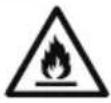 | AVVERTENZA | Questo simbolo indica che questo dispositivo usa un refrigerante infiammabile. Se il refrigerante perde ed è esposto a una fonte di ignizione esterna, c'è un rischio di incendio. |
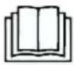 | ATTENZIONE | Questo simbolo indica che il manuale operativo deve essere letto con attenzione. |
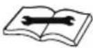 | ATTENZIONE | Questo simbolo indica che il personale addetto all'assistenza deve maneggiare questo dispositivo con riferimento al manuale di installazione. |
 | ATTENZIONE | Questo simbolo indica che sono disponibili informazioni quali il manuale operativo o il manuale di installazione. |
2 Misure di sicurezza
L'installazione o il funzionamento errati non conformi a queste istruzioni possono causare pericolo o danni a persone, proprietà, ecc.
Attenzione
- Questo elettrodomestico può essere utilizzato dai bambini dagli 8 anni in su e dalle persone con capacità fisiche, sensoriali o mentali ridotte, anche in caso di mancata esperienza o conoscenza, solo se controllati e istruiti all'uso sicuro dell'elettrodomestico e informati sui possibili rischi. Non consentire ai bambini di giocare con l'apparecchio. La pulizia e la manutenzione non devono essere effettuate dai bambini senza sorveglianza. (Solo per condizionatori con marchio CE)
- Questo elettrodomestico non è destinato all'utilizzo da parte di persone (compresi i bambini) con capacità fisiche, sensoriali o mentali ridotte o che non posseggono la dovuta esperienza e conoscenza, a meno che non siano controllate o istruite all'uso dell'elettrodomestico da una persona responsabile della loro sicurezza. I bambini devono essere sorvegliati per assicurarsi che non giochino con l'elettrodomestico. (Ad eccezione dei condizionatori con marchio CE)
2 Misure di sicurezza
Il condizionatore deve essere collegato a terra. Una messa a terra incompleta può provocare scosse elettriche. Non collegare il cavo di terra al gasdotto, alla conduttura dell'acqua, al parafulmine o al cavo di terra del telefono. Non collegare il cavo di terra al gasdotto, alla conduttura dell'acqua, al parafulmine o al cavo di terra del telefono. | Spegnere sempre il dispositivo e rimuovere l'alimentazione quando l'unità non è usata per lungo tempo per garantire la sicurezza.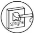 |
Fare attenzione a non bagnare il telecomando o l'unità interna o utilizzarli in condizioni di estrema umidità.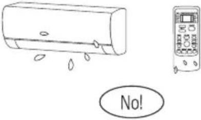 In caso contrario, ciò potrebbe causare un cortocircuito. In caso contrario, ciò potrebbe causare un cortocircuito. | Se il cavo di alimentazione è danneggiato, deve essere sostituito dal produttore o dal suo agente di assistenza o da una persona qualificata con responsabilità simili.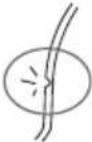 |
2 Misure di sicurezza
Non spegnere l'interruttore durante il funzionamento o con le mani bagnate.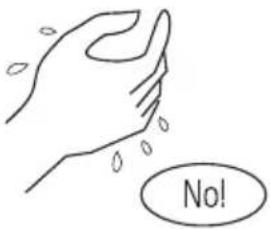 in quanto ciò può causare scosse elettriche. in quanto ciò può causare scosse elettriche. | Non condividere la presa con altri apparecchi elettrici.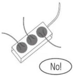 In caso contrario, ciò potrebbe causare scosse elettriche o addirittura incendio ed esplosione. In caso contrario, ciò potrebbe causare scosse elettriche o addirittura incendio ed esplosione. |
Spegnere sempre il dispositivo e interrompere l'alimentazione elettrica prima di eseguire qualsiasi intervento di manutenzione o pulizia.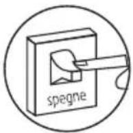 In caso contrario, potrebbero verificarsi scosse elettriche o il dispositivo potrebbe danneggiarsi. In caso contrario, potrebbero verificarsi scosse elettriche o il dispositivo potrebbe danneggiarsi. | Non tirare il cavo di alimentazione.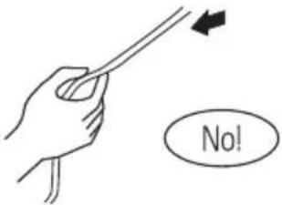 Il danneggiamento del cavo di alimentazione potrebbe causare gravi scosse elettriche. Il danneggiamento del cavo di alimentazione potrebbe causare gravi scosse elettriche. |
2 Misure di sicurezza
| Un avvertimento che i condotti collegati a un dispositivo non devono contenere una fonte di ignizione. | Non installare il condizionatore in un luogo in cui siano presenti gas o liquidi infiammabili. La distanza da questo tipo di gas o liquidi deve essere superiore a 1 m.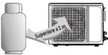 Potrebbe causare un incendio. Potrebbe causare un incendio. |
Non utilizzare detergenti liquidi o corrosivi per pulire il condizionatore né cospargere d'acqua o altri liquidi.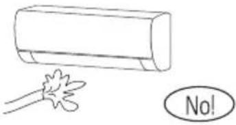 Ciò potrebbe causare scosse elettriche o danni all'unità. Ciò potrebbe causare scosse elettriche o danni all'unità. | Non tentare di riparare il condizionatore da soli.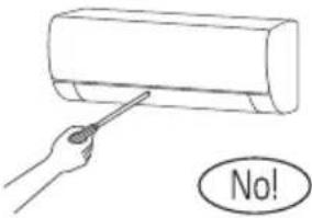 Riparazioni errate possono causare scosse elettriche o incendi. Contattare un tecnico dell'assistenza qualificato per tutte le richieste di assistenza. Riparazioni errate possono causare scosse elettriche o incendi. Contattare un tecnico dell'assistenza qualificato per tutte le richieste di assistenza. |
2 Misure di sicurezza
Non usare il condizionatore in caso di tempeste con fulmini.
L'alimentazione elettrica deve essere interrotta in tempo per evitare il verificarsi di situazioni di pericolo.
Verificare se il supporto installato sia abbastanza stabile.
natural_image
Line drawing of a portable air conditioner unit with grid and wheels (no text or symbols)Se è danneggiato, può portare alla caduta dell'unità e causare lesioni.
Non introdurre le mani o altri oggetti nelle prese d'aria di entrata o di uscita.
Ciò potrebbe causare lesioni personali o danni all'unità.
Non bloccare l'ingresso o l'uscita dell'aria.
natural_image
Illustration of a kitchen appliance with a grater, cubes, and a sphere, no text or symbols presentIn caso contrario, la capacità di raffreddamento o di riscaldamento sarà indebolita e potrebbe anche verificarsi l'interruzione del sistema.
2 Misure di sicurezza
Non lasciare che il condizionatore emetta aria contro l'apparecchio di riscaldamento.
natural_image
Illustration of a spray gun emitting vapor onto a wall-mounted air conditioner (no text or symbols)In caso contrario si genererà una combustione incompleta, causando così avvelenamento.
È necessario installare un interruttore differenziale con capacità nominale per evitare possibili scosse elettriche.
L'elettrodomestico deve essere installato in conformità con le normative di cablaggio nazionali.
- Questo prodotto contiene gas fluorurati a effetto serra.
- Le perdite di refrigerante hanno un effetto negativo sul cambiamento climatico. Il refrigerante con un potenziale di riscaldamento globale inferiore (GWP) ha un effetto meno negativo sul riscaldamento globale di un refrigerante con GWP più elevato, se disperso nell'atmosfera. Questo apparecchio contiene un fluido refrigerante con un GWP pari a [675]. Ciò significa che se 1 kg di questo fluido refrigerante viene rilasciato nell'atmosfera, l'impatto sul riscaldamento globale sarebbe [675] volte superiore a 1 kg di CO2, in un periodo di 100 anni. Non tentare mai di interferire con il circuito del refrigerante o di smontare il prodotto da soli e chiedere sempre assistenza a un professionista.
- Assicurarsi che non vi siano gli oggetti seguenti sotto l'unità interna:
- microonde, forni e altri oggetti caldi.
- computer e altri apparecchi elettrostatici.
2 Misure di sicurezza
-
prese che si inseriscono frequentemente.
-
Le giunzioni tra l'unità interna e quella esterna non devono essere riutilizzate, a meno che dopo aver risistemato il tubo.
- Le specifiche del fusibile sono riportate sul circuito stampato, ad esempio: 3,15 A/250 V CA, ecc.
Avvertenza WEEE
Significato del bidone con ruote barrato:
Non smaltire apparecchiature elettriche come rifiuti indifferenziati, ma servirsi di impianti per la raccolta appositi.
Contattare l'ente territoriale preposto per informazioni concernenti i sistemi di raccolta disponibili.
Se le apparecchiature elettriche sono smaltite in discariche, le sostanze pericolose possono penetrare nelle falde acquifere ed entrare nella catena alimentare, diventando un pericolo per la salute.
Quando si sostituiscono vecchi apparecchi con nuovi, il rivenditore è legalmente obbligato ad accettare il vecchio apparecchio restituito dall'utente ai fini di smaltimento almeno gratuitamente.
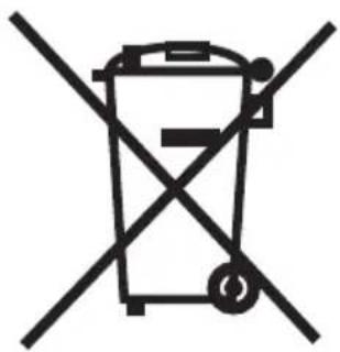
natural_image
Symbol of a trash bin crossed with two diagonal lines, no text or numbers presentQuesto simbolo indica che questo prodotto non deve essere smaltito con altri rifiuti domestici al termine della sua vita utile. Il dispositivo usato deve essere portato a un punto di raccolta ufficiale per il riciclaggio di dispositivi elettrici ed elettronici. Per individuare questi punti di raccolta, contattare le proprie autoritàlocali oppure il rivenditore presso cui èstato acquistato il prodotto. Ciascuna famiglia ha un ruolo importante nel recupero e riciclaggio di vecchi apparecchi. Lo smaltimento appropriato degli apparecchi usati aiuta a prevenire potenziali conseguenze negative per l'ambiente e la salute umana.
2 Misure di sicurezza
Quando il condizionatore è in funzione non aprire finestre e porte a lungo.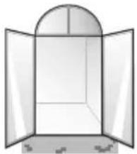 In caso contrario, la capacità di raffreddamento o di riscaldamento sarà indebolita. In caso contrario, la capacità di raffreddamento o di riscaldamento sarà indebolita. | Non posizionarsi sulla parte superiore dell'unità esterna né collocare oggetti pesanti su di essa.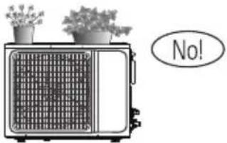 Ciò potrebbe causare lesioni personali o danni all'unità. Ciò potrebbe causare lesioni personali o danni all'unità. |
Non utilizzare il condizionatore per altri scopi, come asciugare i vestiti, conservare cibi, ecc.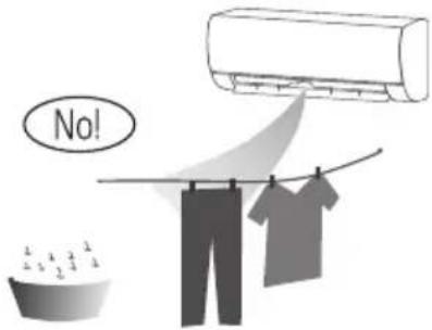 | Non applicare aria fredda in direzione del corpo per lungo tempo.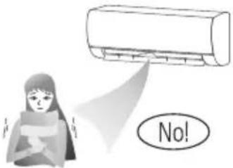 Danneggerà le proprie condizioni fisiche e causerà problemi di salute. Danneggerà le proprie condizioni fisiche e causerà problemi di salute. |
2 Misure di sicurezza
Impostare la temperatura adatta.
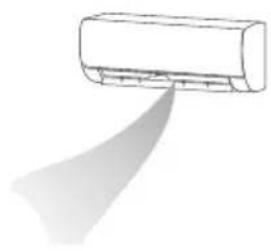
natural_image
Simple line drawing of a car air conditioner with a spray arc (no text or symbols)Si consiglia che la differenza di temperatura tra la temperatura interna ed esterna non sia eccessiva.
Adeguate regolazioni della temperatura di impostazione possono impedire lo spreco di elettricità.
Se il condizionatore non è dotato di un cavo di alimentazione e di una presa, è necessario installare un interruttore onnipolare nel cablaggio fisso con una distanza tra i contatti non inferiore a 3,0 mm.
- Se il condizionatore è collegato in modo permanente al cablaggio fisso, nel cablaggio fisso deve essere installato un dispositivo a corrente residua (RCD) anti-esplosione con corrente di funzionamento residua non superiore a 30 mA.
- Il circuito di alimentazione deve disporre di un dispositivo di protezione contro le perdite e un interruttore pneumatico di cui la capacità dovrebbe essere superiore a 1,5 volte la corrente massima.
- Per quanto riguarda l'installazione dei condizionatori, fare riferimento ai paragrafi seguenti in questo manuale.
3 Note per l'uso
3.1 Condizioni in cui l'unità normalmente non funziona
- Nell'intervallo di temperatura indicato nella seguente tabella, il condizionatore potrebbe arrestarsi e potrebbero verificarsi altre anomalie.
| Raffreddamento | Esterno | >43°C (si applica a T1) |
| >52°C (si applica a T1) | ||
| Interno | <18°C | |
| Riscaldamento | Esterno | >24°C |
| <-7°C | ||
| Interno | >27°C |
- Quando la temperatura è troppo alta, il condizionatore può attivare il dispositivo automatico di protezione, in modo che il condizionatore possa essere spento.
- Quando la temperatura è troppo bassa, lo scambiatore di calore del condizionatore potrebbe congelarsi, causando perdite d'acqua o altri malfunzionamenti.
- In caso di raffreddamento o deumidificazione a lungo termine con un'umidità relativa superiore all'80% (in condizione di porte e finestre aperte), potrebbe verificarsi condensa o gocciolamento di acqua vicino all'uscita dell'aria.
• T1 e T3 fanno riferimento allo standard ISO 5151.
3.2 Note per il riscaldamento
- La ventola dell'unità interna non inizierà a funzionare immediatamente dopo l'avvio del riscaldamento per evitare la fuoriuscita di aria fredda.
- Quando è freddo e umido all'esterno, l'unità esterna svilupperà brina sullo scambiatore di calore che comprometterà la capacità di riscaldamento. È in questo momento che il condizionatore inizierà lo sbrinamento.
- Durante lo sbrinamento, il condizionatore arresta il riscaldamento per circa 5-12 minuti.
- Potrebbe fuoriuscire del vapore dall'unità esterna durante lo sbrinamento. Questa condizione non è sintomo di malfunzionamento, ma il risultato del rapido sbrinamento veloce.
- Il riscaldamento riprenderà al termine dello sbrinamento.
3.3 Note per lo spegnimento
- Quando il condizionatore viene spento, il controller principale deciderà automaticamente se fermarsi immediatamente o dopo essere in funzione per una decina di secondi con una frequenza inferiore e una velocità dell'aria inferiore.
3 Note per l'uso
3.4 Funzionamento di emergenza
- Se il telecomando viene perso o rotto, utilizzare il pulsante dell'interruttore di forzatura per azionare il condizionatore.
- Se questo pulsante viene premuto con l'unità spenta, il condizionatore funzionerà in modalità automatica.
- Se questo pulsante viene premuto con l'unità accesa, il condizionatore si arresterà.
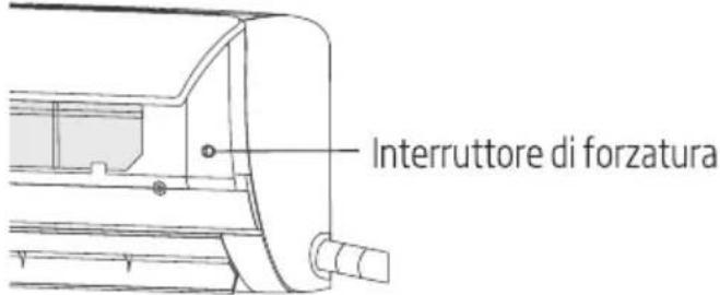
3.5 Regolazione della direzione del flusso d'aria
- Utilizzare i tasti di rotazione su-giù e sinistra-destra sul telecomando per regolare la direzione del flusso d'aria. Fare riferimento al manuale operativo del telecomando per i dettagli.
- Per i modelli senza funzione di rotazione sinistra-destra, le alette devono essere spostate manualmente.
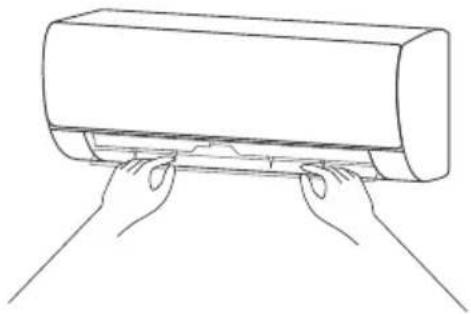
natural_image
Line drawing of two hands pressing down on a cylindrical object (no text or symbols)
Nota:
Spostare le alette prima che l'unità sia messa in funzione per evitare di ferirsi alle dita. Non mettere mai le mani nell'ingresso o nell'uscita dell'aria quando il condizionatore è in funzione.
3 Note per l'uso
3.6 Cautela specifica
- Aprire il pannello frontale dell'unità interna.
- Il connettore (come Fig.) non può toccare la morsettiera, ed è posizionato come mostrato nella Fig.
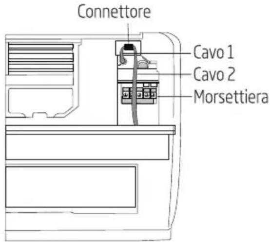
4 Nomi di ciascuna parte
4.1 Unità interna
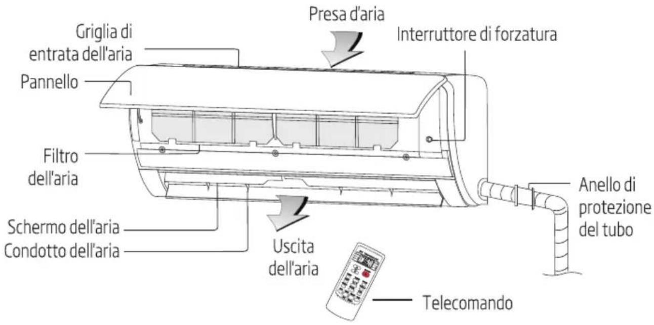
4.2 Unità esterna
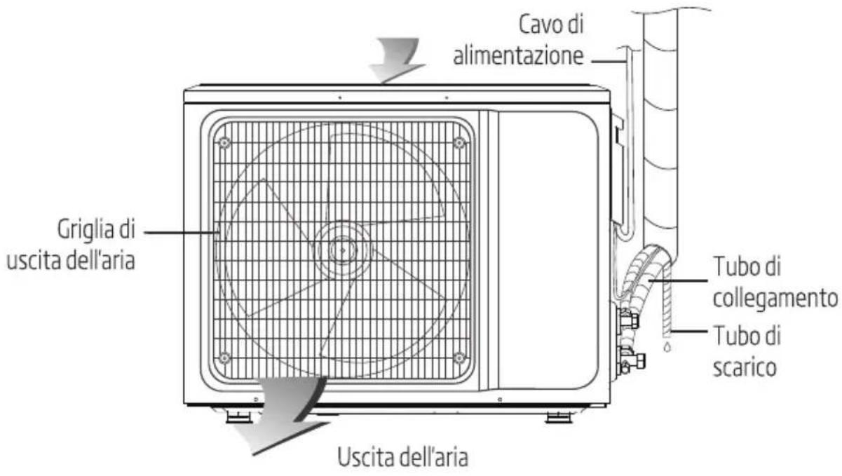

Nota: Tutte le immagini in questo manuale sono solo diagrammi schematici, quelli reali sono standard. La spina, la funzione WIFI, la funzione ioni negativi e la funzione di oscillazione verticale e orizzontale sono opzionali, l'unità effettiva deve prevalere.
5 Pulizia e cura
Avvertenza:
- Prima della pulizia del condizionatore, è necessario spegnerlo e l'elettricità deve essere interrotta per più di 5 minuti, altrimenti potrebbe esserci il rischio di scosse elettriche.
- Non bagnare il condizionatore in quanto ciò può causare una scossa elettrica. Assicurarsi di non sciacquare il condizionatore con acqua in nessuna circostanza.
- Liquidi volatili come diluenti o benzina danneggeranno l'alloggiamento del condizionatore, pertanto si consiglia di pulire l'alloggiamento del condizionatore solo con un panno morbido e asciutto e un panno umido inumidito con detergente neutro.
- Durante l'uso, prestare attenzione alla pulizia del filtro regolarmente, per evitare che accumuli di polvere possano influenzare l'effetto del prodotto. Se l'ambiente di servizio del condizionatore è polveroso, aumentare di conseguenza il numero di sessioni di pulizia. Dopo aver rimosso il filtro, non toccare la parte dell'aletta dell'unità interna con le dita, in modo da evitare di graffiarla.
5.1 Pulizia del pannello
Quando il pannello dell'unità interna è contaminato, pulirlo delicatamente con un asciugamano strizzato utilizzando acqua tiepida sotto i 45 °C e non rimuovere il pannello durante la pulizia.
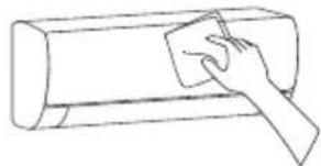
natural_image
Line drawing of a hand pressing down on a cylindrical object (no text or symbols)5.2 Pulire il filtro dell'aria
• Rimozione del filtro dell'aria
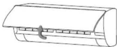
natural_image
Simple line drawing of a cylindrical object with a handle and internal compartments (no text or symbols)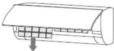
natural_image
Diagram of a car air conditioner unit with cooling fins and airflow direction arrow (no text or labels)- Utilizzare entrambe le mani per aprire il pannello per un angolo da entrambe le estremità del pannello in base alla direzione della freccia.
- Rilasciare il filtro dell'aria dallo slot e rimuoverlo.
5 Pulizia e cura
• Pulire il filtro dell'aria
Utilizzare un aspirapolvere o acqua per risciacquare il filtro. Se il filtro è molto sporco (ad esempio, sporco grasso), pulirlo con acqua calda (a una temperatura inferiore a 45 °C) con un detergente neutro sciolto, e quindi collocare il filtro all'ombra per asciugarsi.
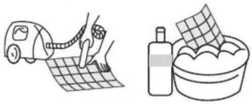
natural_image
Illustration showing a car being cleaned on a grid surface next to a bowl of laundry (no text or symbols)5.3 Pulire il filtro dell'aria
- Montaggio del filtro
- Reinstallare il filtro essiccato nell'ordine inverso rispetto alla rimozione, quindi coprire e bloccare il pannello.
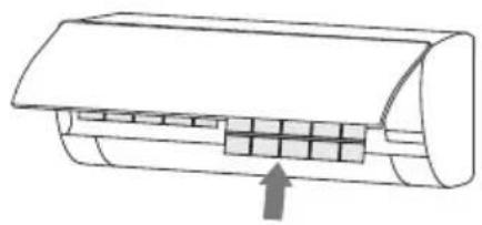
natural_image
Diagram of a car air conditioner unit with cooling fins and airflow direction arrow (no text or labels)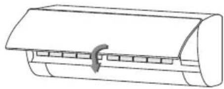
natural_image
Line drawing of a cylindrical object with a clamped handle (no text or symbols)5.4 Controlli prima dell'uso
- Controllare se tutti gli ingressi e le uscite dell'aria delle unità sono sbloccati.
- Controllare se vi è un blocco nell'uscita dell'acqua del tubo di scarico e, se necessario, pulirlo immediatamente.
- Controllare che il cavo di terra sia correttamente collegato a terra.
- Controllare se le batterie del telecomando sono installate e se la potenza è sufficiente.
- Controllare se vi è presenza di danni nella staffa di montaggio dell'unità esterna e, in caso affermativo, contattare il nostro centro di assistenza locale.
5.5 Manutenzione dopo l'uso
- Interrompere la fonte di alimentazione del condizionatore, spegnere l'interruttore di circuito e rimuovere le batterie dal telecomando.
- Pulire il filtro e il corpo dell'unità.
- Rimuovere la polvere e i detriti dall'unità esterna.
- Controllare se vi è presenza di danni nella staffa di montaggio dell'unità esterna e, in caso affermativo, contattare il nostro centro di assistenza locale.
6 Risoluzione dei problemi

Avvertenza:
- Non riparare autonomamente il condizionatore poiché una manutenzione errata può provocare scosse elettriche o incendi. Contattare il centro di assistenza autorizzato, lasciare che i professionisti eseguano la manutenzione e controllare i seguenti elementi prima di contattare per la manutenzione può far risparmiare tempo e denaro.
Fenomeno
Il condizionatore non funziona.
Il condizionatore non può funzionare dopo l'avvio immediato dopo il suo spegnimento.
Il condizionatore smette di funzionare per un po' dopo che si avvia.
Risoluzione dei problemi
- Potrebbero esserci interruzioni di corrente → Attendere fino al ripristino della corrente.
- La spina di alimentazione potrebbe essere staccata dalla presa. → La spina nella presa inserita correttamente.
- Il fusibile dell'interruttore di alimentazione potrebbe saltare. Sostituire il fusibile.
- Il momento del boot non è ancora giunto. → Attendere o annullare le impostazioni del timer.
- Se il condizionatore viene acceso immediatamente dopo lo spegnimento, l'interruttore di ritardo di protezione ritarderà l'operazione di 3-5 minuti.
- Può raggiungere la temperatura di impostazione. → È un fenomeno di normale funzionamento.
- Potrebbe essere in uno stato di scongelamento. → Si ripristinerà e si riavvierà automaticamente dopo lo sbrinamento.
- Il timer di spegnimento può essere impostato. → Se si continua a utilizzare, riaccenderlo.
6 Risoluzione dei problemi
Fenomeno
Il vento si spegne, ma l'effetto di raffreddamento/ riscaldamento non è buono.
Risoluzione dei problemi
- L'eccessivo accumulo di polvere sul filtro, ostruzione all'entrata e all'uscita dell'aria e l'angolo troppo piccolo delle alette del deflettore influenzano l'effetto di raffreddamento e riscaldamento. → Pulire il filtro, rimuovere le ostruzioni all'ingresso e all'uscita dell'aria e regolare l'angolo delle alette del deflettore.
- Scarso effetto di raffreddamento e riscaldamento causato dall'apertura di porte e finestre e dalla ventola di scarico non chiusa. → Chiudere porte, finestre, ventola di scarico ecc.
- La funzione di riscaldamento ausiliario non viene attivata durante il riscaldamento, il che può causare un cattivo effetto di riscaldamento. → Accendere la funzione di riscaldamento ausiliario. (solo per modelli con funzione di riscaldamento ausiliario)
- L'impostazione della modalità non è corretta e le impostazioni di temperatura e velocità del vento non sono appropriate. → Riselezionare la modalità e impostare la temperatura e la velocità del vento appropriate.
L'unità interna emette un odore.
Si sente un rumore di acqua corrente durante il funzionamento del condizionatore.
Si sente un leggero suono di "clic" al momento dell'avvio o dello spegnimento.
- Il condizionatore non emette odore sgradevole. Se si percepisce un certo odore, potrebbe essere dovuto all'accumulo di odore nell'ambiente. → Pulire il filtro dell'aria o attivare la funzione di pulizia.
- Quando il condizionatore viene avviato o arrestato, o il compressore viene avviato o arrestato durante la marcia, a volte si sente il suono "sibilante" dell'acqua corrente. → Questo è il suono del flusso del refrigerante, non indice di un malfunzionamento.
- A causa dei cambiamenti di temperatura, il pannello e le altre parti si gonfiano, causando il rumore di attrito. → Questo è normale, non è un difetto.
6 Risoluzione dei problemi
Fenomeno
L'unità interna emette suoni anomali.
Ci sono gocce d'acqua sulla superficie dell'unità interna.
Durante l'operazione di raffreddamento, l'uscita dell'unità interna a volte emetterà della nebbiolina.
Risoluzione dei problemi
- Il suono del relè della ventola o del compressore è stato attivato o disattivato.
- Quando lo sbrinamento viene avviato o smette di funzionare, suonerà. → Ciò è dovuto al fatto che il refrigerante scorre nella direzione opposta. Non sono malfunzionamenti.
- Un eccessivo accumulo di polvere nel filtro dell'aria dell'unità interna può provocare fluttuazioni del suono. → Pulire i filtri dell'aria in tempo.
- Troppo rumore d'aria quando si attiva "Vento forte". → Questo è normale, se ci si sente disagio, disattivare la funzione "Vento forte".
- Quando l'umidità ambientale è elevata, si accumulano gocce d'acqua attorno all'uscita dell'aria o al pannello ecc. → Si tratta di un normale fenomeno fisico.
- Raffreddamento prolungato nello spazio aperto produce gocce d'acqua. → Chiudere le porte e le finestre.
- Anche un angolo di apertura troppo piccolo delle lamelle del deflettore può provocare gocce d'acqua all'ingresso dell'aria. → Aumentare l'angolo delle alette del deflettore.
- Quando la temperatura e l'umidità interna sono elevate, a volte succede. → Questo perché l'aria interna viene raffreddata rapidamente. Dopo un po' di tempo, la temperatura interna e l'umidità si ridurranno e la nebbiolina sparirà.

Avvertenza:
Interrompere immediatamente tutte le operazioni e l'alimentazione, contattare il nostro centro di assistenza locale nelle seguenti situazioni.
- Sentire un qualsiasi suono stridulo o un cattivo odore durante il funzionamento.
- Si verifica un riscaldamento anomalo del cavo di alimentazione e della spina.
• L'unità o il telecomando hanno impurità o acqua.
• L'interruttore dell'aria o l'interruttore di protezione dalle perdite è spesso scollegato.
7 Note relative all'installazione
Note importanti:
- Prima dell'installazione, contattare il centro di manutenzione autorizzato locale, se l'unità non è installata dal centro di manutenzione autorizzato, il malfunzionamento potrebbe non risolversi a causa di un contatto poco dettagliato.
- Il condizionatore deve essere installato da professionisti in base alle norme di cablaggio nazionali e al presente manuale.
- Il test di tenuta del refrigerante deve essere effettuato dopo l'installazione.
- Per spostare e installare il condizionatore in un'altra posizione contattare il nostro centro di assistenza speciale locale.
7.1 Disimballaggio Ispezione
- Aprire l'alloggiamento e controllare il condizionatore in una zona con una buona ventilazione (aprire la porta e la finestra) e senza fonte di accensione. Nota: Gli operatori devono indossare dispositivi antistatici.
- È necessario verificare da parte del professionista se ci sono perdite di refrigerante prima di aprire l'alloggiamento dell'unità esterna; interrompere l'installazione del condizionatore in caso di perdite.
- Le attrezzature antincendio e le precauzioni antistatiche devono essere preparate molto prima del controllo. Quindi controllare la tubazione del refrigerante per vedere se ci sono tracce di collisione e se la vista è buona.
7.2 Principi di sicurezza per l'installazione del condizionatore
- Il dispositivo antincendio deve essere preparato prima dell'installazione.
- Mantenere il sito di installazione ventilato (aprire la porta e la finestra)
- Non è consentita fonte di accensione, fumare e telefonare nell'area in cui si trova il refrigerante R32.
- Precauzioni antistatiche necessarie per l'installazione del condizionatore, ad es. indossare vestiti e guanti di puro cotone.
- Tenere il rilevatore di perdite in funzione durante l'installazione.
- Se durante l'installazione si verificano perdite di refrigerante R32, è necessario rilevarne immediatamente la concentrazione nell'ambiente interno fino a raggiungere un livello di sicurezza. Se la perdita di refrigerante influisce sulle prestazioni del condizionatore, interrompere immediatamente il funzionamento e il condizionatore deve essere svuotato e restituito alla stazione di manutenzione per il funzionamento.
- Tenere l'apparecchio elettrico, l'interruttore di alimentazione, la spina, la presa, la fonte di calore ad alta temperatura e l'alta elettricità statica lontano dall'area sottostante le linee laterali dell'unità interna.
- Il condizionatore deve essere installato in un luogo accessibile per l'installazione e la manutenzione, senza ostacoli che possano ostruire gli ingressi o le uscite dell'aria delle unità interne/esterne e deve essere tenuto lontano da fonti di calore, condizioni infiammabili o esplosive.
7 Note relative all'installazione
- Durante l'installazione o la riparazione del condizionatore e se la linea di collegamento non è abbastanza lunga, l'intera linea di collegamento deve essere sostituita con una linea di collegamento delle specifiche originali; la prolunga non è consentita.
- Utilizzare una nuova tubazione di collegamento, a meno che non si verifichi il risvoltamento del tubo.
7.3 Requisiti per la posizione di installazione
- Evitare luoghi con perdite di gas infiammabili o esplosivi o in presenza di gas fortemente aggressivi.
- Evitare luoghi soggetti a forti campi elettrici/magnetici artificiali.
- Evitare luoghi soggetti a rumore e risonanza.
- Evitare condizioni naturali estreme (ad es. forte nerofumo, forte vento sabbioso, luce diretta del sole o fonti di calore ad alta temperatura).
- Evitare luoghi alla portata dei bambini.
- Accorciare il collegamento tra le unità interne ed esterne.
- Selezionare dove è facile eseguire interventi di manutenzione e riparazione e dove la ventilazione è sufficiente.
- L'unità esterna non deve essere installata in alcun modo che possa occupare un corridoio, una scala, un'uscita, una scala antincendio, una passerella o qualsiasi altra area pubblica.
- L'unità esterna deve essere installata il più lontano possibile dalle porte e dalle finestre dei vicini e dalle piante verdi.
7.4 Ispezione dell'ambiente di installazione
- Controllare la targhetta dell'unità esterna per accertarsi che il refrigerante sia R32.
- Controlla lo spazio del pavimento della stanza. Lo spazio non deve essere inferiore allo spazio utilizzabile (5m2) nelle specifiche. L'unità esterna deve essere installata in un luogo ben ventilato.
- Controllare l'ambiente circostante del sito di installazione: R32 non deve essere installato in uno spazio chiuso di un edificio.
- Quando si utilizza un trapano elettrico per praticare fori nel muro, verificare prima se sono presenti condotte pre-interrate per acqua, elettricità e gas. Si consiglia di utilizzare il foro riservato nel muro.
7.5 Requisiti della struttura di montaggio
- Il rack di montaggio deve soddisfare gli standard nazionali o industriali pertinenti in termini di resistenza con aree di saldatura e di connessione antiruggine.
- Il supporto di montaggio e la relativa superficie di carico devono essere in grado di resistere a 4 volte o più il peso dell'unità, o 200 kg, a seconda di quale è più pesante.
- Il supporto di montaggio dell'unità esterna deve essere fissato con un bullone di espansione.
7 Note relative all'installazione
- Garantire l'installazione sicura indipendentemente dal tipo di muro su cui è installato, per evitare possibili cadute che potrebbero ferire le persone.
7.6 Requisiti di sicurezza elettrica
- Assicurarsi di utilizzare il circuito dedicato della tensione nominale e dei condizionatori per l'alimentazione e il diametro del cavo di alimentazione deve soddisfare i requisiti nazionali.
- Quando la corrente massima del condizionatore è ≥ 16 A, deve utilizzare l'interruttore dell'aria o l'interruttore di protezione dalle perdite dotato di dispositivi di protezione.
- Il normale intervallo operativo è del 90%-110% della tensione nominale locale.
- La distanza minima tra il condizionatore e i combustibili è di 1,5 m.
- Il cavo di interconnessione collega le unità interne ed esterne. È necessario innanzitutto scegliere il cavo adatto prima di prepararlo per il collegamento.
- Tipi di cavi: Cavo di alimentazione per esterni: H07RN-F o H05RN-F; Cavo di alimentazione: H07RN-F o H05RN-F;
- Area minima della sezione trasversale dell'alimentazione e dei relativi cavi
Nord America
| Ampere (A) dell'apparecchio | AWG |
| 10 | 18 |
| 13 | 16 |
| 18 | 14 |
| 25 | 12 |
| 30 | 10 |
| 40 | 8 |
Altre regioni
| Corrente nominale assorbita dall'apparecchiatura (A) | Area della sezione trasversale nominale ( mm^2 ) |
| >3e≤6 | 0,75 |
| >6e≤10 | 1 |
| >10e≤16 | 1,5 |
| >16e≤25 | 2,5 |
| >25e≤32 | 4 |
| >32e≤40 | 6 |
- La dimensione dei cavi di interconnessione, del fusibile e dell'interruttore necessari è determinata dalla corrente massima dell'unità. La corrente massima assorbita è indicata sulla targhetta riportata sul pannello laterale dell'unità. Per scegliere il cavo, il fusibile o l'interruttore più adatti, fare riferimento alla targhetta.

Nota: Il numero di core del cavo si riferisce allo schema elettrico dettagliato apposto sull'unità acquistata.
7 Note relative all'installazione
7.7 Requisiti per le operazioni in altezza sollevata
- Quando si esegue l'installazione a 2 m o più al di sopra del livello base, è necessario indossare cinture di sicurezza e funi sufficientemente resistenti da fissare saldamente all'unità esterna, per prevenire cadute che potrebbero causare lesioni personali o morte nonché perdita della proprietà.
7.8 Requisiti di messa a terra
- Il condizionatore è di tipo I e deve garantire una messa a terra affidabile.
- Non collegare il cavo di messa a terra a un tubo del gas, a un tubo dell'acqua, a un parafulmine, a una linea telefonica o a un circuito non correttamente collegato a terra.
- Il cavo di messa a terra è appositamente progettato e non deve essere utilizzato per altri scopi, né deve essere fissato con una vite di presa comune.
- Il diametro del cavo di interconnessione deve essere raccomandato secondo il manuale di istruzioni e con terminale tipo O conforme agli standard locali (il diametro interno del terminale di tipo O deve corrispondere alla dimensione della vite dell'unità, non più di 4,2 mm). Dopo l'installazione, controllare che le viti siano state fissate in modo efficace e non vi sia alcun rischio di allentamento.
7.9 Altro
- Il metodo di connessione del condizionatore e del cavo di alimentazione e il metodo di interconnessione di ciascun elemento indipendente devono essere soggetti allo schema elettrico apposto sulla macchina.
- Il modello e il valore nominale del fusibile devono essere soggetti alla serigrafia sul controller corrispondente o sul manicotto del fusibile.
7.10 Contenuto della confezione
Lista di imballaggio dell'unità interna
| Nome | Quantità | Unità |
| Unità interna | 1 | Imposta |
| Telecomando | 1 | PEZZO |
| Batterie (7) | 2 | PEZZO |
| Istruzioni | 1 | Imposta |
| Tubo di scarico | 1 | PEZZO |
Lista di imballaggio dell'unità esterna
| Nome | Quantità | Unità |
| Unità esterna | 1 | Imposta |
| Tubo di collegamento | 2 | PEZZO |
| Cinturino in plastica | 1 | ROTOLO |
| Anello di protezione del tubo | 1 | PEZZO |
| Cementazione (mastice) | 1 | PACCO |
Nota: Tutti gli accessori devono essere conformi al materiale di imballaggio effettivo e, in caso di differenze, ci auguriamo comprensione da parte dell'utente.
8.1 Disegno quotato dell'installazione dell'unità interna
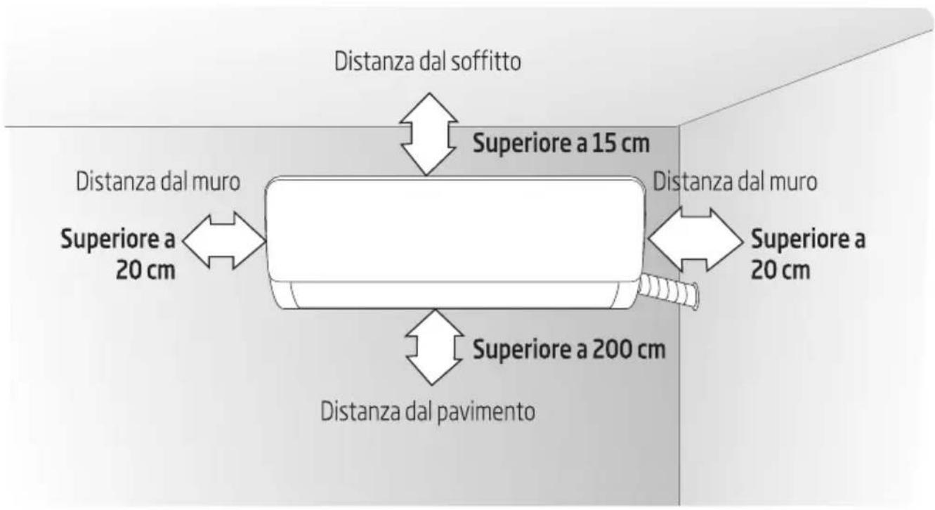
8.2 Piastra di montaggio
- Il muro per l'installazione dell'unità interna deve essere rigido e stabile, in modo da evitare vibrazioni.
- Utilizzare la vite di tipo "+" per fissare la scheda di ancoraggio, montare orizzontalmente la scheda di ancoraggio sulla parete e assicurare la verticale orizzontale e longitudinale laterale.
- Tirare il pannello forato dopo l'installazione, per confermare se è solido.
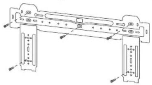
natural_image
Technical line drawing of a mechanical assembly with mounting brackets and mounting holes (no text or symbols)8.3 Foro passante
- Praticare un foro con un martello elettrico o un trapano ad acqua nella posizione predeterminata sulla parete per le tubazioni, con un'inclinazione verso l'esterno di 5°-10°.
- Per proteggere le tubazioni e i cavi da danneggiamenti che attraversano la parete e dai roditori che possono entrare nella parete cava, deve essere installato un anello di protezione dei tubi e sigillato con mastice.
8 Installare l'unità interna
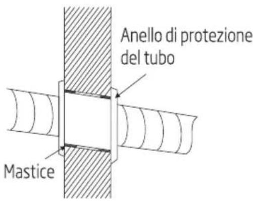

Nota: Solitamente il foro nel muro ha dimensioni pari a ∅ 60 mm\~∅ 80 mm. Evitare cavi di alimentazione pre-interrati e pareti rigide quando si effettua il foro.
8.4 Percorso delle tubazioni
- A seconda della posizione dell'unità, le tubazioni possono essere dirette lateralmente da sinistra o destra (Fig 1), o verticalmente dal retro (Fig 2) (a seconda della lunghezza del tubo dell'unità interna). In caso di percorso laterale, tagliare il gruppo di taglio di uscita del lato opposto.
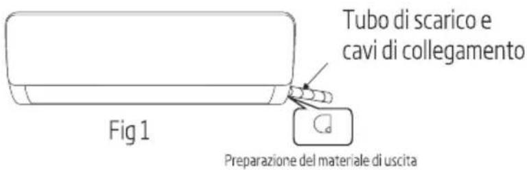
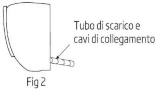
8.5 Collegamento del tubo di scarico
- Rimuovere i supporti e tirare fuori il tubo dell'unità interna dall'alloggiamento.
- Collegare il tubo di collegamento all'unità interna:
Mirare al centro del tubo, serrare il dado conico con le dita, quindi serrare il dado conico con una chiave dinamometrica (direzione mostrata nello schema a destra). La coppia utilizzata è mostrata nella seguente tabella.

Nota: Controllare con attenzione la presenza di danni alle giunzioni prima dell'installazione. Le giunzioni non devono essere riutilizzate, a meno che dopo aver risistemato il tubo.
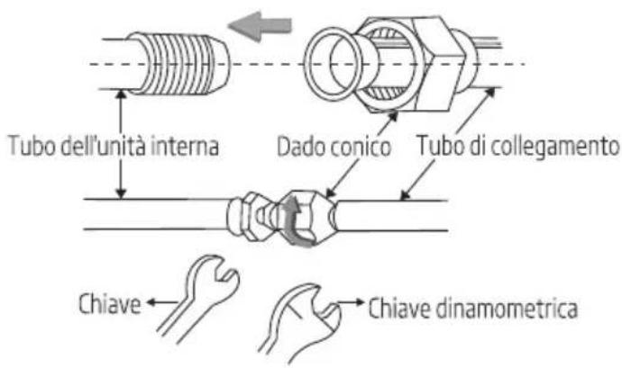
Tabella della coppia di serraggio
| Dimensione del tubo (mm) | Coppia (Nm) |
| 06/06,35 | 15~25 |
| 09/09,52 | 35~40 |
| 012/012,7 | 45~60 |
| 015,88 | 73~78 |
| 019,05 | 75~80 |
8.6 Avvolgimento delle tubazioni
- Utilizzare la guaina isolante per avvolgere la parte del giunto dell'unità interna e il tubo di collegamento, quindi utilizzare materiale isolante per imballare e sigillare il tubo di isolamento, per evitare la generazione di acqua di condensa sulla parte del giunto.
- Collegare l'uscita dell'acqua con i tubi di scarico e fare in modo che il tubo di collegamento, i cavi e il tubo di scarico siano dritti.
- Utilizzare fascette di plastica per avvolgere i tubi di collegamento, i cavi e il tubo di scarico. Fare scorrere il tubo verso il basso.
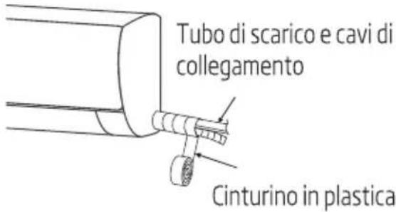
8 Installare l'unità interna
8.7 Fissaggio dell'unità interna
- Appoggiare l'unità interna sulla scheda di ancoraggio e spostare l'unità da sinistra a destra per assicurarsi che il gancio sia posizionato correttamente nella scheda di ancoraggio.
- Spingere verso il lato inferiore sinistro e il lato superiore destro dell'unità verso la scheda di ancoraggio, finché il gancio non scatta in posizione nello slot con un "clic".
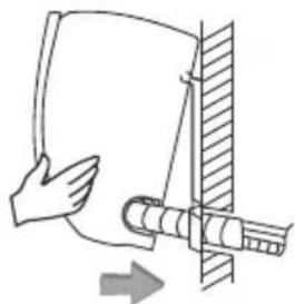
natural_image
Diagram of a hand holding a cylindrical object with a pipe inserted, showing an arrow indicating direction (no text or symbols present)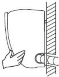
natural_image
Simple line drawing of a hand holding a cylindrical object next to a vertical wall (no text or symbols)8.8 Schema di cablaggio
- Se il condizionatore è dotato di cavo di alimentazione, il cablaggio dell'unità interna è collegato in fabbrica, non è necessario alcun collegamento.
- Se il cavo di alimentazione non è fornito, è necessaria la connessione secondo lo schema elettrico
Dopo l'installazione, controllare che
- le viti siano state fissate in modo efficace e non vi sia alcun rischio di allentamento.
- il connettore della scheda video sia posto nella giusta posizione e non toccare la morsettiera.
- Controllare la tenuta del coperchio della scatola.
Velocità costante
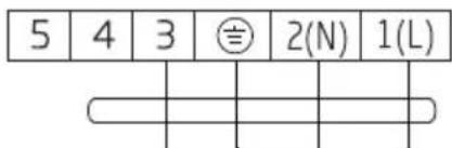
Verso l'unità esterna
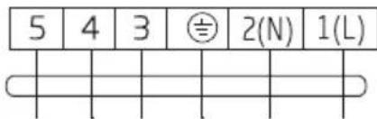
Verso l'unità esterna
Velocità variabile
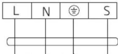
Verso l'unità esterna
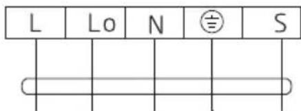
Verso l'unità esterna
Connettore
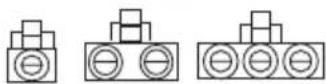
Se è presente un connettore,
collegarlo direttamente.
8 Installare l'unità interna

Nota:
- Questo manuale di solito include la modalità di cablaggio per i diversi tipi di condizionatore. Non possiamo escludere la possibilità che alcuni tipi speciali di schemi elettrici non siano inclusi.
- Lo schema è fornito solo per riferimento. Se l'entità è diversa da questo schema elettrico, fare riferimento allo schema elettrico dettagliato applicato sull'unità acquistata.
9.1 Disegno quotato dell'installazione dell'unità esterna
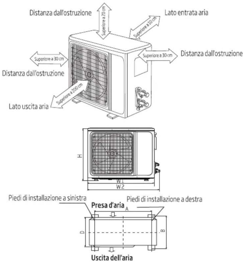
Installazione del bullone dell'unità esterna
| Dimensioni unità esterne di forma W1 (W2) * H * D) (mm) | A (mm) | B (mm) |
| 665 (710) × 420 × 280 | 430 | 280 |
| 600 (645) × 485 × 260 | 400 | 290 |
| 660 (710) × 500 × 240 | 500 | 260 |
| 700 (745) × 500 × 255 | 460 | 260 |
| 730 (780) × 545 × 285 | 540 | 280 |
| 760 (810) × 545 × 285 | 540 | 280 |
| 790 (840) × 550 × 290 | 545 | 300 |
| 800 (860) × 545 × 315 | 545 | 315 |
| 800 (850) × 590 (690) × 310 | 540 | 325 |
9 Installare l'unità esterna
| 825 (880) × 655 × 310 | 540 | 335 |
| 900 (950) × 700 × 350 | 630 | 350 |
| 900 (950) × 795 × 330 | 535 | 350 |
| 970 (1044) × 803 × 395 | 675 | 409 |
9.2 Installazione del tubo di collegamento
Collegare l'unità esterna con il tubo di collegamento: Puntare il controdado del tubo di collegamento sulla valvola di arresto e serrare il dado conico con le dita. Quindi serrare il dado conico con una chiave dinamometrica.
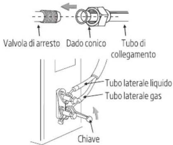
- Quando si prolungano le tubazioni, è necessario aggiungere ulteriore quantità di refrigerante in modo che il funzionamento e le prestazioni del condizionatore non vengano compromesse.
| Lunghezza delle tubazioni | Quantità di refrigerante da aggiungere | Quantità di refrigerante per l'unità | |
| ≤ 5 M | Non necessario | ||
| 5-15 M | CC ≤ 12000 Btu | 16 g/m | ≤ 1 kg |
| CC ≤ 18000 Btu | 24 g/m | ≤ 2 kg | |
Nota:
- La tabella è fornita solo per riferimento.
- Le giunzioni non devono essere riutilizzate, a meno che dopo aver risistemato il tubo.
- Dopo l'installazione, controllare se il coperchio della valvola di arresto è stato fissato in modo efficace.
9 Installare l'unità esterna
9.3 Connessione dei cavi
- Allentare le viti e rimuovere il coperchio delle parti elettroniche dall'unità.
- Collegare i cavi rispettivamente ai corrispondenti morsetti della morsettiera dell'unità esterna (vedere lo schema elettrico). Se vi sono segnali collegati alla spina, eseguire semplicemente il giunto di testa.
- Cavo di terra: Rimuovere la vite di messa a terra dalla staffa elettrica, coprire l'estremità del cavo di messa a terra sulla vite di messa a terra e avvitarla nel foro di messa a terra.
- Fissare il cavo in modo sicuro con i dispositivi di fissaggio (scheda a pressione).
- Rimettere il coperchio delle parti elettroniche nella relativa posizione originale e fissarlo con le viti.
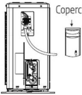
Coperchio delle parti elettroniche
9.4 Schema di cablaggio
Velocità costante
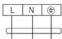
Verso alimentazione
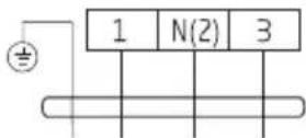
Verso unità interna
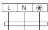
Verso alimentazione
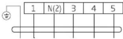
Verso unità interna
Velocità variabile
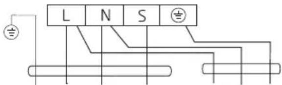
Verso unità interna
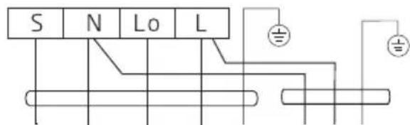
Verso unità interna
Verso alimentazione
Connettore

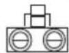
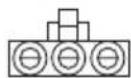

Se è presente un connettore, collegarlo direttamente.
9 Installare l'unità esterna
Nota:
Questo manuale di solito include la modalità di cablaggio per i diversi tipi di condizionatore. Non possiamo escludere la possibilità che alcuni tipi speciali di schemi elettrici non siano inclusi.
Lo schema è fornito solo per riferimento. Se l'entità è diversa da questo schema elettrico, fare riferimento allo schema elettrico dettagliato applicato sull'unità acquistata.
9.5 Aspirazione
- L'esclusiva pompa del refrigerante R32 deve essere utilizzata per l'aspirazione del refrigerante R32.
Prima di lavorare sul condizionatore, rimuovere il coperchio della valvola di arresto (valvole del gas e del liquido) e assicurarsi di riavviarlo successivamente. (per evitare potenziali perdite d'aria)
- Per evitare perdite d'aria e fuoriuscite, serrare tutti i dadi di collegamento di tutti i tubi svasati.
- Collegare la valvola di arresto, il flessibile di carica, la valvola del collettore e la pompa del vuoto.
- Aprire completamente la maniglia Lo della valvola del collettore e applicare il vuoto per almeno 15 minuti e controllare che il vacuometro composto indichi -0,1 MPa (-76 cm Hg).
- Dopo aver applicato il vuoto, aprire completamente la valvola di arresto con una chiave esagonale.
- Verificare che i collegamenti interni ed esterni siano privi di perdite d'aria.
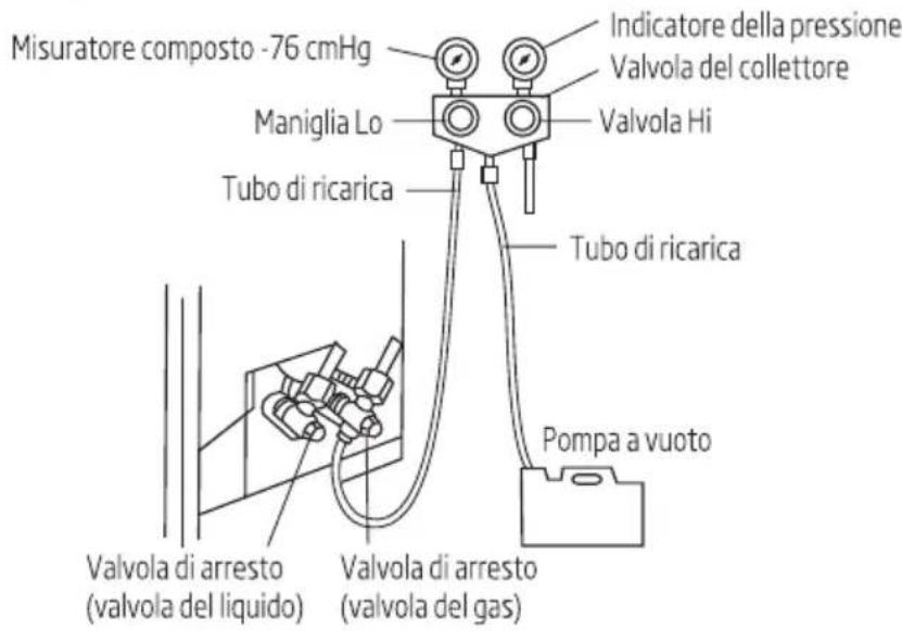
9 Installare l'unità esterna
9.6 Scarico condensa esterno (solo modello con pompa di calore)
Quando l'unità è in fase di riscaldamento, l'acqua di condensazione e l'acqua di sbrinamento possono fuoriuscire in modo affidabile attraverso l'alloggiamento dello scarico.
Installazione:
Installare il gomito dello scarico esterno in un foro di ∅ 25 sulla piastra di base e congiungere il tubo di scarico al gomito, in modo che l'acqua di scarico formata nell'unità esterna possa essere scaricata su una piastra adeguata.
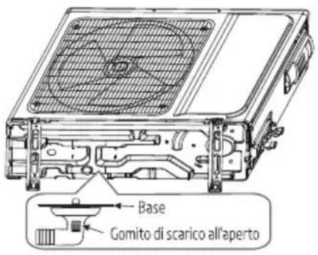
10 Controllare dopo l'installazione e il funzionamento di prova
10.1 Controlli dopo l'installazione
- Verifiche sulla sicurezza elettrica
- Se la tensione di alimentazione rispetta i requisiti.
- Se è presente una connessione difettosa o mancata in ciascuno dei cavi di alimentazione, di segnale e di messa a terra.
- Se il cavo di messa a terra del condizionatore è saldamente collegato a terra.
- Verifica della sicurezza dell'installazione
- Se l'installazione è sicura.
- Se lo scarico dell'acqua è regolare.
- Se il cablaggio e le tubazioni sono installati correttamente.
- Verificare che non siano rimasti corpi estranei o strumenti all'interno dell'unità.
- Controllare che la tubazione del refrigerante sia protetta bene.
- Test di tenuta del refrigerante
A seconda del metodo di installazione, è possibile utilizzare i seguenti metodi per verificare la presenza di perdite sospette, su aree come le quattro connessioni dell'unità esterna e i nuclei delle valvole di intercettazione e delle valvole a T:
- Metodo a bolle: Applicare uno spruzzo uniforme di acqua saponata sul punto di fuga sospetto e osservare attentamente la presenza di bolle.
- Metodo dello strumento: Controllare la perdita puntando la sonda del rilevatore di perdite in base alle istruzioni sui punti sospetti di perdita.

Nota: Assicurarsi che la ventilazione sia buona prima di controllare.
10.2 Prova di funzionamento
Preparazione della prova di funzionamento:
- Verificare che tutte le tubazioni e i cavi di collegamento siano ben collegati.
- Confermare che i valori sul lato gas del lato liquido siano completamente aperti.
- Collegare il cavo di alimentazione a una presa di corrente indipendente.
• Installare le batterie nel telecomando.

Nota: Assicurarsi che la ventilazione sia buona prima del test.
10 Controllare dopo l'installazione e il funzionamento di prova
Metodo di prova:
- Accendere l'alimentazione e premere il pulsante dell'interruttore On/Off (Accensione/Spegnimento) del telecomando per avviare il condizionatore.
- Selezionare Cool (Raffreddamento), Heat (Riscaldamento) (non disponibile sui modelli a solo raffreddamento), SWING e altre modalità operative con il telecomando e verificare se l'operazione è corretta.
11 Avviso relativo alla manutenzione

Nota: Per manutenzione o rottamazione, contattare i centri di assistenza autorizzati. La manutenzione da parte di personale non qualificato può causare pericoli.
Alimentare il condizionatore con refrigerante R32 e manutenzionare il condizionatore secondo i requisiti del produttore. Il capitolo si concentra principalmente sui requisiti di manutenzione speciali per apparecchi con refrigerante R32. Chiedere al riparatore di leggere il manuale di assistenza tecnica post-vendita per informazioni dettagliate.
11.1 Requisiti di qualifica del personale di manutenzione
- È richiesto una formazione speciale aggiuntiva alle consuete procedure di riparazione delle apparecchiature di refrigerazione quando si tratta di attrezzatura con refrigeranti infiammabili. In molti paesi, questa formazione viene fornita da organizzazioni nazionali di formazione che sono accreditate per insegnare i pertinenti standard di competenza nazionali che possono essere stabiliti nella legislazione. La competenza acquisita dovrebbe essere documentata da un certificato.
- La manutenzione e la riparazione del condizionatore devono essere condotte secondo il metodo raccomandato dal produttore. Se altri professionisti sono necessari per aiutare a manutenzionare e riparare l'attrezzatura, tali interventi dovrebbero essere condotti sotto la supervisione di persone che hanno la qualifica per riparare condizionatori dotati di refrigerante infiammabile.
11.2Ispezione del sito
Prima di effettuare la manutenzione del dispositivo con refrigerante R32, condurre un'ispezione al fine di assicurarsi che il rischio di incendio sia ridotto al minimo. Controllare che il luogo sia ben ventilato e che le attrezzature antistatiche e antincendio siano perfette.
Durante la manutenzione del sistema di refrigerazione, osservare le seguenti precauzioni prima di utilizzare il sistema.
11.3 Procedure operative
1. Area di lavoro generale
Tutto il personale di manutenzione e gli altri che lavorano nell'area locale devono essere istruiti sulla natura del lavoro svolto. Il lavoro in spazi ristretti deve essere evitato. L'area intorno allo spazio di lavoro deve essere sezionata. Assicurarsi che le condizioni all'interno dell'area siano state rese sicure dal controllo del materiale infiammabile.
2. Controllo della presenza di refrigerante
L'area deve essere controllata con un rilevatore di refrigerante adeguato prima e durante il lavoro, per assicurarsi che il tecnico sia consapevole della presenza di ambienti potenzialmente infiammabili o tossici. Assicurarsi che le apparecchiature di rilevamento delle perdite in uso siano adatte per l'uso con refrigeranti infiammabili, ovvero senza scintille, adeguatamente sigillate o a sicurezza intrinseca.
11 Avviso relativo alla manutenzione
3. Presenza di estintori:
Se si deve effettuare un intervento a caldo nelle apparecchiature di refrigerazione o in qualsiasi parte associata, tenere a portata di mano dispositivi antincendio. Tenere un estintore a polvere asciutta o con CO2 nei pressi dell'area di carica.
4. Nessuna fonte di combustione:
Il personale che interviene in un sistema di refrigerazione esponendo le tubazioni non deve utilizzare fonti di combustione in modo che possa comportare il rischio di incendio o esplosione. Il personale non deve essere fumare durante l'intervento. Tutte le possibili fonti di combustione, comprese fumare, devono essere tenuti sufficientemente lontane dal sito di installazione, riparazione, rimozione e smaltimento, durante il quale il refrigerante può essere rilasciato nello spazio circostante. Prima dell'intervento, è necessario controllare l'area intorno alle apparecchiature per assicurarsi che non vi siano pericoli infiammabili o rischi di combustione.
Devono essere apposti cartelli di "Vietato fumare".
5. Area ventilata (aprire porta e finestra):
Assicurarsi che l'area sia aperta o venga adeguatamente ventilata prima di intervenire nel sistema o effettuare qualsiasi intervento a caldo. Fornire un grado di ventilazione continua durante il periodo dell'intervento. La ventilazione deve disperdere in modo sicuro il refrigerante rilasciato e preferibilmente espellerlo all'esterno nell'atmosfera.
6. Controlli alle apparecchiature di refrigerazione:
I componenti elettrici sostituiti devono essere idonei allo scopo e alle specifiche corrette. Attenersi sempre alle linee guida di manutenzione e assistenza del produttore. In caso di dubbi, rivolgersi al reparto tecnico del produttore per assistenza. I seguenti controlli devono essere applicati agli impianti che utilizzano refrigeranti infiammabili:
- la quantità di carica deve essere conforme alle dimensioni della stanza in cui sono installate le parti contenenti refrigerante;
- i macchinari e le prese di ventilazione devono funzionare in modo adeguato e non devono essere ostruite;
- se viene utilizzato un circuito di refrigerazione indiretta, il circuito secondario deve essere controllato per verificare la presenza di refrigerante.
- Il tubo o i componenti di refrigerazione sono installati in una posizione in cui è improbabile che possano essere esposti a qualsiasi sostanza che possa corrodere componenti contenenti refrigerante, a meno che i componenti non siano realizzati con materiali che sono intrinsecamente resistenti alla corrosione o adeguatamente protetti da corrosione.
7. Controlli ai dispositivi elettrici:
La riparazione e la manutenzione di componenti elettrici comprendono controlli di sicurezza iniziali e procedure di ispezione dei componenti. In presenza di un guasto che potrebbe compromettere la sicurezza, l'alimentazione elettrica non deve essere collegata al circuito finché il guasto non
11 Avviso relativo alla manutenzione
viene riparato in modo soddisfacente. Se il guasto non può essere riparato immediatamente, ma è necessario continuare l'operazione, adottare un'adeguata soluzione temporanea. Il proprietario del materiale deve essere informato o avvisato in modo che possa avvisare tutti.
I controlli di sicurezza iniziali devono comprendere, senza limiti:
- lo scaricamento dei condensatori: questa operazione deve essere eseguita in modo sicuro per evitare scintille.
- Non devono esservi componenti elettrici sotto tensione e cablaggio esposto durante la carica, il recupero o lo spurgo del sistema;
- Mantenere la continuità della messa a terra.
11.4 Ispezione del cavo
- Controllare l'usura, la corrosione, la sovratensione, le vibrazioni del cavo e controllare se vi sono spigoli vivi o altri effetti negativi nell'ambiente circostante. Durante l'ispezione, dovrebbero essere presi in considerazione l'impatto dell'invecchiamento o la vibrazione continua del compressore.
11.5 Controllo di perdita del refrigerante R32
Nota: Controllare la perdita del refrigerante in un ambiente privo di potenziale fonte di ignizione. Non utilizzare una sonda alogena (o qualsiasi altro rilevatore che utilizza una fiamma libera).
Metodi di rilevamento perdite:
Per i sistemi con refrigerante R32, è disponibile uno strumento di rilevamento di perdite elettronico per rilevare e il rilevamento di perdite non deve essere eseguito in ambiente con refrigerante.
Assicurarsi che il rilevatore di perdite non diventi una potenziale fonte di ignizione ed sia applicabile al refrigerante misurato. Il rilevatore di perdite deve essere impostato per la concentrazione minima di combustibile infiammabile (in percentuale) del refrigerante. Calibrare e regolare la giusta concentrazione di gas (non più del 25%) con il refrigerante usato.
Il fluido utilizzato nel rilevamento delle perdite è applicabile alla maggior parte dei refrigeranti. Ma non usare solventi clorurati per prevenire la reazione tra cloro e refrigeranti e la corrosione delle tubazioni in rame.
Se si sospetta una perdita, rimuovere tutto il fuoco dalla scena o spegnere il fuoco.
Se il punto della perdita deve essere saldato, è necessario recuperare tutti i refrigeranti o isolare tutti i refrigeranti dal punto di perdita (utilizzando la valvola di intercettazione). Prima e durante la saldatura, utilizzare OFN per purificare l'intero sistema.
11 Avviso relativo alla manutenzione
11.6Rimozione e pompaggio a vuoto
- Assicurarsi che non vi sia alcuna fonte ignizione accesa vicino all'uscita della pompa a vuoto e che la ventilazione sia buona.
-
Lasciare che la manutenzione e le altre operazioni del circuito di refrigerazione siano eseguite secondo la procedura generale, ma le seguenti migliori operazioni che l'infiammabilità è già stata presa in considerazione sono la chiave. Si dovrebbero seguire le seguenti procedure:
-
Rimuovere il refrigerante.
- Decontaminare la tubazione con gas inerti.
• Evacuazione. - Decontaminare nuovamente la tubazione con gas inerti.
-
Tagliare e saldare la tubazione.
-
Il refrigerante deve essere riposto nel serbatoio di stoccaggio appropriato. Il sistema dovrebbe essere soffiato con azoto privo di ossigeno per garantire la sicurezza. Questo processo potrebbe dover essere ripetuto più volte. Questa operazione non deve essere eseguita utilizzando aria compressa o ossigeno.
-
Attraverso il processo di soffiaggio, il sistema viene caricato nell'azoto anaerobico per raggiungere la pressione di lavoro in stato di vuoto, quindi l'azoto privo di ossigeno viene emesso nell'atmosfera e, alla fine, rende l'impianto vuoto. Ripetere questo processo fino a quando tutti i refrigeranti nel sistema non sono stati eliminati. Dopo il caricamento finale dell'azoto anaerobico, scaricare il gas nella pressione atmosferica, quindi il sistema può essere saldato. Questa operazione è necessaria per saldare la tubatura.
11.7 Procedure di ricarica dei refrigeranti
Come supplemento alla procedura generale, è necessario aggiungere i seguenti requisiti:
- Accertarsi che non vi siano contaminazioni tra i diversi refrigeranti quando si utilizza un dispositivo di caricamento del refrigerante. La tubazione per caricare i refrigeranti dovrebbe essere la più corta possibile per ridurre il residuo di refrigeranti.
- I serbatoi di stoccaggio dovrebbero essere posti verticalmente.
- Assicurarsi che le soluzioni di messa a terra siano già state prese prima che il sistema di refrigerazione sia carico di refrigeranti.
- Dopo aver terminato la ricarica (o quando non è ancora finita), apporre il contrassegno sul sistema.
- Fare attenzione a non sovraccaricare i refrigeranti.
11 Avviso relativo alla manutenzione
11.8 Rottamare e recuperare
Rottamare:
Prima di questa procedura, il personale tecnico deve conoscere a fondo l'apparecchiatura e tutte le sue caratteristiche e fare k pratica raccomandata per il recupero sicuro del refrigerante. Per riciclare il refrigerante, analizzare i campioni di refrigerante e olio prima dell'uso. Garantire la potenza richiesta prima del test.
- Familiarizzare con l'attrezzatura e il funzionamento.
- Scollegare l'alimentazione.
-
Prima di eseguire questo processo, è necessario assicurarsi:
-
Se necessario, il funzionamento del dispositivo meccanico dovrebbe facilitare il funzionamento del serbatoio del refrigerante.
- Tutti i dispositivi di protezione individuale sono efficaci e possono essere utilizzati correttamente.
• L'intero processo di recupero dovrebbe essere condotto sotto la guida di personale qualificato. -
Il recupero delle attrezzature e del serbatoio di stoccaggio devono essere conformi alle norme nazionali pertinenti.
-
Se possibile, il sistema di refrigerazione dovrebbe essere vuoto.
-
Se non è possibile raggiungere lo stato di vuoto, è necessario estrarre il refrigerante in ogni parte del sistema da più punti.
-
Prima dell'inizio del recupero, è necessario assicurarsi che la capacità del serbatoio di stoccaggio sia sufficiente.
-
Avviare e utilizzare l'attrezzatura di recupero in base alle istruzioni del produttore.
-
Non riempire completamente il serbatoio (il volume di iniezione del liquido non supera l'80% del volume del serbatoio).
-
Anche la durata è breve, non deve superare la pressione massima di esercizio del serbatoio.
-
Dopo il completamento del riempimento del serbatoio e la fine del processo operativo, è necessario assicurarsi che i serbatoi e l'attrezzatura debbano essere rimossi rapidamente e che tutte le valvole di chiusura nell'apparecchiatura siano chiuse.
-
I refrigeranti recuperati non possono essere iniettati in un altro sistema prima di essere purificati e testati.

Nota: L'identificazione deve essere effettuata dopo la rottamazione dell'apparecchio e l'evacuazione dei refrigeranti. L'identificazione dovrebbe contenere la data e l'approvazione. Assicurarsi che l'identificazione sull'apparecchio rifletta i refrigeranti infiammabili contenuti in questo apparecchio.
11 Avviso relativo alla manutenzione
Recupero:
- La rimozione dei refrigeranti nel sistema è necessaria per la riparazione o la rottamazione dell'apparecchio. Si consiglia di rimuovere completamente il refrigerante.
- È possibile utilizzare solo un serbatoio del refrigerante speciale quando si carica il refrigerante nel serbatoio di stoccaggio. Assicurarsi che la capacità del serbatoio sia adeguata alla quantità di iniezione del refrigerante nell'intero sistema. Tutti i serbatoi destinati a essere utilizzati per il recupero di refrigeranti devono avere un identificativo del refrigerante (ad esempio il serbatoio di recupero del refrigerante). I serbatoi di stoccaggio devono essere dotati di valvole limitatrici di pressione e valvole a globo e devono essere in buone condizioni. Se possibile, i serbatoi vuoti devono essere evacuati e mantenuti a temperatura ambiente prima dell'uso.
- L'apparecchiatura di recupero deve essere tenuta in buone condizioni di lavoro e dotata di istruzioni operative per l'accesso facilitato. L'apparecchiatura dovrebbe essere idonea per il recupero di refrigeranti R32. Inoltre, dovrebbe esserci un dispositivo di ponderazione idoneo che può essere utilizzato normalmente. Il tubo deve essere collegato con un giunto di collegamento rimovibile con tasso di perdita zero e mantenuto in buone condizioni. Prima di utilizzare il dispositivo di recupero, controllare se è in buone condizioni e se garantisce una manutenzione perfetta. Controllare se tutti i componenti elettrici sono sigillati per evitare la perdita del refrigerante e il conseguente incendio. In caso di domande, consultare il produttore.
- Il refrigerante recuperato deve essere caricato negli appositi serbatoi di stoccaggio, sui cui sono apposte le istruzioni di trasporto e restituito al produttore del refrigerante. Non mescolare il refrigerante nelle apparecchiature di recupero, in particolare un serbatoio di stoccaggio.
- Lo spazio di carico del refrigerante R32 non può essere racchiuso nel processo di trasporto. Prendere misure anti-elettrostatiche se necessario durante il trasporto. Nel processo di trasporto, carico e scarico, devono essere prese le necessarie misure protettive per proteggere il condizionatore per garantire che non si danneggi.
- Quando si rimuove il compressore o si scarica l'olio del compressore, assicurarsi che il compressore sia pompato ad un livello appropriato per garantire che non vi siano refrigeranti R32 residui nell'olio lubrificante. Il pompaggio del vuoto deve essere eseguito prima che il compressore venga restituito al fornitore. Garantire la sicurezza durante lo scarico di olio dal sistema.
12 Istruzioni per l'installazione
12.1F-Gas - Istruzioni
Questo prodotto contiene gas fluorurati ad effetto serra contemplati dal protocollo di Kyoto.
I gas fluorurati ad effetto serra sono contenuti in attrezzatura sigillata ermeticamente.
Installazioni, riparazioni, manutenzione, controlli della presenza di perdite, smantellamento e riciclo del prodotto devono essere effettuati da personale qualificato.
Se il sistema è dotato di dispositivo per il rilevamento delle perdite, i controlli delle perdite devono essere eseguiti almeno ogni 12 mesi, accertando che il sistema funzioni correttamente.
Ogni qual volta vengono eseguiti controlli delle perdite, occorre specificare il ciclo di controllo, creare e conservare dei registri concernenti le verifiche.

Nota: Non occorre eseguire le verifiche delle perdite per attrezzatura sigillata ermeticamente, condizionatori d'aria portatili, condizionatori d'aria a finestra e deumidificatori, se l'equivalente di CO₂ o gas fluorurati ad effetto serra è minore di 10 tonnellate.
13 Specifiche
| Nome modello Beko | BIVPA 090/ BIVPA 091 | BIVPA 120/ BIVPA 121 | BIVPA 180/ BIVPA 181 | BIVPA 240/ BIVPA 241 |
| Tipo di refrigerante | R32 | R32 | R32 | R32 |
| Quantità refrigerante totale (g) | 580 | 680 | 1280 | 1440 |
| Equivalente di CO2 (tonnellate) | 0.392 | 0.459 | 0.864 | 0.972 |
| Classe climatica | T1 | T1 | T1 | T1 |
| Tipo di riscaldamento | Pompa di calore | Pompa di calore | Pompa di calore | Pompa di calore |
| Connessione alimentatore | Esterno | Esterno | Esterno | Esterno |
| Capacità di raffreddamento (Btu/h) (PdesignC) | 8189 | 11942 | 18084 | 22860 |
| Intervallo della capacità di raffreddamento (Btu/h) | 2730-8872 | 3140-12283 | 4435-18425 | 6825-25930 |
| Capacità di raffreddamento (W) (PdesignC) | 2400 | 3500 | 5300 | 6700 |
| Intervallo della capacità di raffreddamento (W) | 800-2600 | 1000-3600 | 1300-5400 | 2000-7600 |
| Capacità di riscaldamento (Btu/h) (PdesignC) | 8872 | 9212 | 15013 | 19448 |
| Intervallo della capacità di riscaldamento (Btu/h) | 2730-9215 | 4095-11953 | 4776-20813 | 8530-27296 |
| Capacità di riscaldamento (W) (PdesignC) | 2600 | 2700 | 4400 | 5700 |
| Intervallo della capacità di riscaldamento (W) | 800-2700 | 1200-3500 | 1400-4730 | 2500-8000 |
13 Specifiche
| SEER (UE) (W/W) | 6.1 | 6.1 | 6.1 | 6.1 |
| SCOP (stagione media UE) (W/W) | 4.0 | 4.0 | 4.0 | 4.0 |
| Livello di energia per raffreddamento (UE) | A++ | A++ | A++ | A++ |
| Livello di energia per riscaldamento (UE) | A+ | A+ | A+ | A+ |
| Potenza di raffreddamento in ingresso (W) | 800 | 1090 | 1650 | 2200 |
| Potenza di riscaldamento in ingresso (W) | 750 | 970 | 1490 | 1960 |
| Tensione/Frequenza (V/Hz) | 220-240V~ 50Hz, 1Ph | 220-240V~ 50Hz, 1Ph | 220-240V~ 50Hz, 1Ph | 220-240V~ 50Hz, 1Ph |
| Livello potenza rumore: unità interna (dBA) (potenza suono) | 53 | 52 | 57 | 60 |
| Livello potenza rumore: unità esterna (dBA) (potenza suono) | 57 | 58 | 61 | 64 |
| Livello pressione rumore: unità interna (potenza suono) | 42/35/31 | 42/36/31 | 46/42/37 | 49/43/38 |
| Livello pressione rumore: unità esterna (dBA) (potenza suono) | 52 | 52 | 54 | 55 |
| Volume flusso d'aria (m3/h) | 600/500/450 | 600/500/450 | 850/800/750 | 1150/1100/1040 |
| Rimozione umidità (L/H.r) | 0.9 | 1.2 | 1.75 | 2.5 |
| Elevazione max. (m) | 10 | 10 | 15 | 15 |
| Lunghezza max. tubo (m) | 20 | 20 | 25 | 25 |
13 Specifiche
| Intervallo di temperatura: operativa (°C)Raffreddamento esterno | 16°C ~ 48°C | 16°C ~ 48°C | 16°C ~ 48°C | 16°C ~ 48°C |
| Intervallo di temperatura: operativa (°C)Riscaldamento esterno | -10°C ~ 30°C | -10°C ~ 30°C | -10°C ~ 30°C | -10°C ~ 30°C |
- Le specifiche sono valori standard calcolati in base alle condizioni operative nominali. Queste variano in base alle condizioni di lavoro.
- La nostra azienda apporta rapidi miglioramenti tecnici. Eventuali modifiche ai dati tecnici verranno apportate senza preavviso. Leggere la targhetta sul condizionatore d'aria.
- Il valore corretto viene testato sotto 35/24 (ingresso) 35/24 (uscita).
- Equivalente di CO2 (tonnellate)
| Importer in PolandImporter W PolsceBeko S.A.ul. Puławska 36602-819 Warszawawww.beko.pl | Importer in Czech RepublicDovozce do České republikyBEKO S.A., organizační složkaBucharova 1423/6,Praha 13 - Nové Butovice, 158 00www.bekocr.cz | Importer in SlovakiaDovozca na SlovenskoBEKO Slovakia s.r.o.Suché myto 1811 03 Bratislavawww.bekosk.sk | Importer in EstoniaImportija EestiBeko S.A.Tānav Puławska 36602-819 Varssavi (Poola) | |||
| Importer in GermanyBeko Deutschland GmbHThomas-Edison-Platz 363263 Neu-Isenburg | Importer in UKBEKO Plc, Beko House,1 Greenhill Crescent,Watford, Herts,WD18 8QU | KSA ImporterAL BABTAIN TRADING CO.P.O. Box # 181,Riyadh 11411-KSA+966-11-4744788 | Importer in FranceBEKO France / ImmeubleStadium,266 Avenue duPrésident Wilson,93210,St-Denis La Plaine Cedex | |||
| Importer in SpainBEKO ELECTRONICSESPANA S.L.C/ Provenza388 1° Piso / 08025Barcelona | Importer for MaltaETV LTD119/120Archbishop StreetVALLETTA MALTA | Importer in LatviaImportētāja LatvijāBeko S.A.Ielas Puławska 36602-819 Varšava (Polija) | Importer in LithuaniaImportuotojas LietuvojeBeko S.A.Gatvė Puławska 36602-819 Varšuva (Lenkija) | |||
| Importer in AustriaELEKTRA BREGENZ AGPFARRGASSE 77VIENNA post code 1230 | Importer in SwitzerlandGrundig Nordic ABIsafjordsgatan 39B 16440Kista SWEDEN | Importer in HungaryHauser Magyarorszag imitedBaross utca 89 PC: 2040Budaörs / Hungary | Importer in SloveniaBIG BANG, D.O.O.Šmartinska cesta 152PC: 1000Ljubljana/Slovenia | Importer in ItalyBEKO ITALY SRLViale Del Ghisallo,20/I-20151 Milano (MI) | ||
| Importer in RomaniaARCTIC S.A.Str. 13 Decembrie, nr.210Gäeşti, 135200, Româniawww.arctic.ro | Importer in BeneluxSchaliënhoevedreefB - 2800Mechelen - Belgium | Importer in GreecePAR. SEITANIDIS S.A.Polistilo, P.O. Box:1402Kavala, 64003 | Importer in BulgariaVideolux LTD /PO Box 2109 /2109 Sofia | Importer in CroatiaE PLUS doo ZA Unutarnju /GOSPODARSKA 16c /10225 GORNJISTUPNIK / ZAGREP | ||
| Importer in Russia Импортер на территории РФ: ООО «БЕКО», 601021, Россия, Владимирская область,Киржачский район, деревня Федоровское, улица Сельская, 49Бесплатная линия сервисного обслуживания и информационной поддержки по установке и эксплуатации (только длязвонков по России) 8-800-200-23-56Изготовитель: Arcelik A.Ş. Турция, Karaagac caddesi No: 2-6 Istanbul 34445 Sutluce, Istanbul | ||||||
| Виробник: «Arçelik A.Ş» Karaağaç Caddesi No: 2-6, Sütlüce, 34445 İstanbul, Turkey, «Arçelik A.Ş», м. Стамбул,Сютлюдже, вул. Караагач No 2-6, 34445, ТуреччинаІмпортер на території України:ТОВ «Беко Україна», адреса: 03150, м. Київ, вул. Антоновича, буд. 72, тел/факс.: 0-800-500-4-3-2 Термін служби 3 роки | ||||||
| Manufactured by Arcelik A.S. Karaagac Cd. No:2-6 34445 Sutluce, Beyoglu, Istanbul, Turkey 19/10 Rev: 01 | ||||||
Prodotto da Arcelik A.S. Karaagac Cd. No:2-6 34445 Sutluce, Beyoglu, Istanbul, Turchia

natural_image
Abstract geometric design with blue triangular shapes on white background (no text or symbols)
- Split type wall mounted air-conditioner
- Please read this user manual first!
- Meanings of the symbols
- Contents
- Install indoor unit 29
- Install outdoor unit 34
- Check after installation and test operation 39
- Maintenance Notice 41
- Warning
- Warning:
- Note:
- Safety precautions
- Warning
- WEEE Warning
- Notices for use
- The conditions of unit can't normally run
- Notes for heating
- Notes for turning off
- Emergency operation
- Airflow direction adjustment
- Specific caution
- Names of each part
- Indoor unit
- Outdoor unit
- Clean and care
- Clean the panel
- Clean the air filter
- - Remove the air filter
- - Clean the air filter
- Clean the air filter
- - Mount the filter
- Check before use
- Maintain after use
- Troubleshooting
- Phenomenon
- Troubleshooting
- Immediately stop all operations and cut off the power supply, contact our Service center locally in following situations.
- Notices for installation
- Important notices
- Unpacking Inspection
- Safety Principles for Installing Air Conditioner
- Requirements for installation position
- Installation environment inspection
- Requirements of the mounting structure
- Electrical safety requirements
- Requirements for operations at raised height
- Grounding requirements
- Others
- Packing list
- Install indoor unit
- Dimension drawing of indoor unit installation
- Mounting plate
- Wall-through hole
- Route of pipeline
- Drain pipe connection
- Wrap the piping
- Fixing the indoor unit
- Wiring diagram
- Install outdoor unit
- Install the connection pipe
- Wiring Connection
- Wiring diagram
- Vacuuming
- Outdoor condensation drainage (Heat pump type only)
- Installation:
- Check after installation and test operation
- Check after installation
- • Electrical safety Check
- • Installation safety Check
- - Leak test of the refrigerant
- Test operation
- Test operation preparation:
- Test operation method:
- Maintenance Notice
- Qualification requirements of maintenance personnel
- Inspection of the Site
- Operating Procedures
- General work area:
- Checking for presence of refrigerant:
- Presence of fire extinguisher:
- No ignition sources:
- Ventilated Area(open the door and window):
- Checks to the refrigeration equipment:
- Checks to electrical devices:
- Inspection of Cable
- Leakage check of R32 refrigerant
- Removal and Vacuum Pumping
- Procedures of Charging Refrigerants
- Scrap and Recovery
- Scrap:
- Recovery:
- F-Gas instruction
- Leggere prima il presente manuale!
- Significato dei simboli
- Sommario
- Installare l'unità interna 78
- Installare l'unità esterna 83
- Controllare dopo l'installazione e il funzionamento di prova 88
- Avviso relativo alla manutenzione 90
- Attenzione
- Avvertenza:
- Nota:
- Misure di sicurezza
- Attenzione
- Avvertenza WEEE
- Note per l'uso
- Condizioni in cui l'unità normalmente non funziona
- Note per il riscaldamento
- Note per lo spegnimento
- Funzionamento di emergenza
- Regolazione della direzione del flusso d'aria
- Cautela specifica
- Nomi di ciascuna parte
- Unità interna
- Unità esterna
- Pulizia e cura
- Pulizia del pannello
- Pulire il filtro dell'aria
- • Pulire il filtro dell'aria
- Pulire il filtro dell'aria
- - Montaggio del filtro
- Controlli prima dell'uso
- Manutenzione dopo l'uso
- Risoluzione dei problemi
- Fenomeno
- Risoluzione dei problemi
- Interrompere immediatamente tutte le operazioni e l'alimentazione, contattare il nostro centro di assistenza locale nelle seguenti situazioni.
- Note relative all'installazione
- Note importanti:
- Disimballaggio Ispezione
- Principi di sicurezza per l'installazione del condizionatore
- Requisiti per la posizione di installazione
- Ispezione dell'ambiente di installazione
- Requisiti della struttura di montaggio
- Requisiti di sicurezza elettrica
- Requisiti per le operazioni in altezza sollevata
- Requisiti di messa a terra
- Altro
- Contenuto della confezione
- Disegno quotato dell'installazione dell'unità interna
- Piastra di montaggio
- Foro passante
- Installare l'unità interna
- Percorso delle tubazioni
- Collegamento del tubo di scarico
- Avvolgimento delle tubazioni
- Fissaggio dell'unità interna
- Schema di cablaggio
- Installare l'unità esterna
- Installazione del tubo di collegamento
- Connessione dei cavi
- Schema di cablaggio
- Aspirazione
- Scarico condensa esterno (solo modello con pompa di calore)
- Installazione:
- Controllare dopo l'installazione e il funzionamento di prova
- Controlli dopo l'installazione
- - Verifiche sulla sicurezza elettrica
- - Verifica della sicurezza dell'installazione
- - Test di tenuta del refrigerante
- Prova di funzionamento
- Preparazione della prova di funzionamento:
- Metodo di prova:
- Avviso relativo alla manutenzione
- Requisiti di qualifica del personale di manutenzione
- 11.2Ispezione del sito
- Procedure operative
- Area di lavoro generale
- Controllo della presenza di refrigerante
- Presenza di estintori:
- Nessuna fonte di combustione:
- Area ventilata (aprire porta e finestra):
- Controlli alle apparecchiature di refrigerazione:
- Controlli ai dispositivi elettrici:
- Ispezione del cavo
- Controllo di perdita del refrigerante R32
- 11.6Rimozione e pompaggio a vuoto
- Procedure di ricarica dei refrigeranti
- Rottamare e recuperare
- Rottamare:
- Recupero:
- Istruzioni per l'installazione
- 12.1F-Gas - Istruzioni
- Specifiche
Marke : BEKO
Modell : BIVPA 180
Kategorie : Klimaanlage