
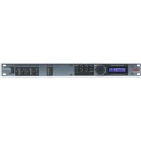
400 - Professionelle Audioausrüstung DBX - Kostenlose Bedienungsanleitung
Finden Sie kostenlos die Bedienungsanleitung des Geräts 400 DBX als PDF.


| Produkttyp | Kompressor/Limiter |
| Modell | 400 |
| Marke | DBX |
| Frequenzgang | 20 Hz - 20 kHz |
| Eingangsimpedanz | 10 kOhm |
| Ausgangsimpedanz | 100 Ohm |
| Maximaler Eingangspegel | +20 dBu |
| Maximaler Ausgangspegel | +20 dBu |
| Kompressionsverhältnis | 2:1 bis unendlich:1 |
| Schwellwertbereich | -40 dBu bis +20 dBu |
| Attack-Zeit | 0,1 ms bis 10 ms |
| Release-Zeit | 0,1 s bis 3 s |
| Stromversorgung | 230 V AC, 50 Hz |
| Leistungsaufnahme | 15 W |
| Abmessungen (B x H x T) | 483 x 44 x 200 mm |
| Gewicht | 2,5 kg |
| Betriebstemperatur | 0°C bis 40°C |
| Gehäuse | 19-Zoll-Rackgehäuse |
| Lieferumfang | Netzkabel, Bedienungsanleitung |
| Garantie | 2 Jahre |
Häufig gestellte Fragen - 400 DBX
Benutzerfragen zu 400 DBX
0 Frage zu diesem Gerät. Beantworten Sie die, die Sie kennen, oder stellen Sie Ihre eigene.
Eine neue Frage zu diesem Gerät stellen
Laden Sie die Anleitung für Ihr Professionelle Audioausrüstung kostenlos im PDF-Format! Finden Sie Ihr Handbuch 400 - DBX und nehmen Sie Ihr elektronisches Gerät wieder in die Hand. Auf dieser Seite sind alle Dokumente veröffentlicht, die für die Verwendung Ihres Geräts notwendig sind. 400 von der Marke DBX.
BEDIENUNGSANLEITUNG 400 DBX

Model 400
Program-Route Selector
Instruction Manual
WARNING: TO PREVENT FIRE OR SHOCK HAZARD, DO NOT EXPOSE THIS UNIT TO RAIN OR MOISTURE.
"dbx" is a registered trademark of dbx Inc., Newton, Mass., USA
INSPECTION and INSTALLATION
Your unit was carefully packed at the factory in a carton designed to protect it. Nevertheless, we recommend examining both carton and contents for any signs of damage. If there is such evidence, don't destroy the carton or any of the packing material, and notify your dbx dealer immediately.
In any case it is a good idea to save the carton and packing materials should you ever need to ship your unit in the future.
In addition to a model 400 and this instruction manual, the carton should contain a set (two pairs) of hookup cables with conventional RCA phono (pin) plugs, mounting brackets, and a warranty/registration card.
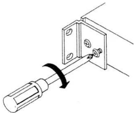
The 400 is mountable into any standard 19-inch (48.3-cm) equipment rack with the supplied brackets. No special cooling or ventilation is required in any installation; other components may be stacked above or below the 400 provided they don't generate excessive heat.
natural_image
Diagram of a screwdriver inserted into a bracket with a rotating knob (no text or symbols)CONTENTS
Front panel (operating instructions) 2
Rear jacks (connections) 4
Some typical hookups .... 5
Usage notes 6
Block diagram....11
Schematic 12
Warranty and factory-service information....13
Important information for users in the United Kingdom....13

READ THIS FIRST
The best place to locate your dbx 400 is in a tape-monitor (record/play) loop in your preamp or receiver ("preamp" from now on). If you have more than one such loop, Tape 1 is the obvious choice. The details about this hookup are given in the next section, "Rear Jacks."
For now, simply note that in order for your new 400 to be in operation -- that is, in the signal path -- the signal always has to be going to and from it. In other words, if you've connected the 400 in the Tape 1 loop, leave the preamp set to monitor Tape 1. If your preamp is one of those that have separate Input Select and Rec Out switches, leave the Select knob (or whatever) on Tape 1 and choose the program source with the Rec Out knob. See "Usage Notes."
FRONT PANEL
(see facing page)
1 SOUND PROCESSORS 1,2,3. These buttons let you switch in and out of operation the sound processor(s) -- equalizer, expander, imager -- connected to the back of the 400.
Push one or more of the buttons to put the corresponding processor(s) into the signal path. You will be sending the musical program through whichever processors are hooked up. Leave the button(s) out to bypass the processor(s).
The processors enter in sequence, of course: 1, then 2, then 3. The yellow LED (light-emitting diode) will light up. Throughout the 400's faceplate "route," a yellow LED indicates the presence of one or more processors in the signal path.
1A SOUND PROCESSORS:PRE, POST, COPY. These buttons control the position of the processor(s) relative to your tape deck(s).
Pushing "Pre" puts the processor(s) ahead of the deck, which means that you can process (equalize, expand, etc.) the signal before it gets recorded. "Post" puts the processor(s) after the deck(s), on playback only, which means that you alter the sound
when you're listening to the tape. Push "Copy" for dubbing: it places signal processor 1,2, or 3 between the playing ("copy master") deck and the recording (receiving) deck(s).
2 MONITOR:LINE,TAPE 1,2,3. Push these buttons to choose what to listen to (monitor). "Line" is your record and/or CD player, radio, TV/VCR, or other source; "Tape" is your deck(s). These buttons control which signal gets returned to your pre-amp from the 400. The yellow LED indicates that the signal is being processed; the green one indicates that it's being decoded. (Decoding is explained next.) Push only one monitor button at a time.
NOISE REDUCTION:DECODE:MONITOR or :COPY, and :ENCODE:LINE or :COPY.
3A The top pair of buttons choose the encoder (record) or decoder ( playback) section of your dbx or other noise-reduction (NR) unit. Pushing both in, of course, permits monitoring of a tape while it's being recorded -- provided your cassette deck and NR unit have this simultaneous capability.
3B The bottom pair of buttons permit the encoding and decoding functions to be inserted separately into a dubbing procedure. That is, the copy master can be either encoded or decoded (if it already is encoded) before being copied by another deck. This is handy for making a Dolby-B cassette of a dbx-encoded tape, for example, to play over your car stereo before you've added a dbx decoder to it.
Leave the bottom buttons out for direct (deck-to-deck) dubbing and for regular tape recording, that is, involving no dubbing.
The red LED under the "Encode" button lights up for that function whenever it is involved, and similar red ones do so "downstream" from (after) the encoder in dubbing procedures.
4 TAPE 1,2,3:COPY MASTER. Push one of these buttons to choose the "Copy Master" tape deck for dubbing. The green and/or yellow LED will light if the NR decoder and/or a signal processor (respectively) are in the dubbing path, between copy master and the copying deck(s).
REC SELECTOR:TAPE 1,TAPE 2,TAPE 3: LINE or :COPY and/or :ENCODE CANCEL.
5A The top row of buttons lets you choose which deck(s) you want to use for recording the line input (record player, radio, etc.) to the 400.
5B The second row of buttons lets you choose which deck(s) do the copying (dubbing) of a tape played on the master deck. The red LEDs indicate whether the NR encoder has been inserted before the receiving deck. If it has, you can encode the signal, of course, before it gets to the copying deck.
For decks that are turned off: press any one of the unused Copy Master buttons,
then press the Copy button for each un- powered deck. (Doing this disconnects them from your system, thereby preventing any adverse interaction with your preamp.) For example, if you're using your Tape 1 deck but not the Tape 2 one (and Tape 3 is empty), push in Copy Master:Tape 2 or 3 (3 is preferable), and also Copy:Tape 2.
Note: before you turn on the unused deck(s) for recording or playing, remember to undo this switching arrangement.
5C This bottom row lets you individually cancel the encoding process to a given deck and yet keep the function active for other decks, as above. In other words, each button will selectively defeat the action of the Noise Reduction:Encode:Copy button setting.
This means, for example, that you can make dbx copies of a particular tape on all the receiving decks except one on which you want to make a Dolby copy.

AC LINE VOLTAGE REQUIREMENT INDICATOR
The recessed indicator displays the nominal AC line voltage for which the 400 has been set at the factory.
AC POWER CABLE
Connect this cable to any 50 or 60 Hz AC power source of the correct line voltage, as shown by the AC LINE VOLTAGE Requirement. The Model 400 requires a maximum of 5 watts AC power.

REAR JACKS, right to left as you face the back panel
See the hookup illustrations on this and the facing page. Note that the one from the top of the unit itself is an overhead, not a rear, view. Note also that the triangles below the 400's jacks point in the direction of signal flow: "Out" (To the other unit) and "In" (From the other unit). Finally, if your cables have a side with red plugs, use it for the right channel.
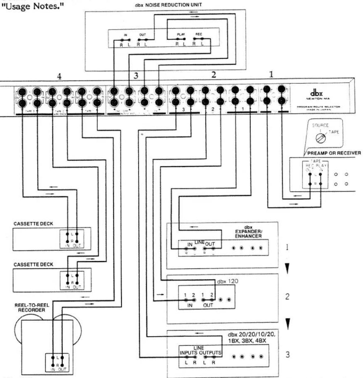
1 LINE. This is where you hook up the model 400 to your preamp. Connect its Tape Out* to the 400's Line In and its Tape In** to the 400's Line Out, left to left, right to right.
2 SOUND PROCESSOR 1,2,3. This is where your equalizer, imager, expander (etc.) go. See the Usage Notes for advice about the order. Connect the appropriate 400 Out (To) jacks to your processor's Input, and connect its Output jacks to the 400's In (From). Follow the triangles.
Repeat for each processor.
3 NOISE REDUCTION UNIT. This is where you put your dbx (or other) noise-reduction (NR) unit.
*Also called Tape Rec, Rec(Out), To Tape Rec, To Tape Inputs, (Out) To Tape, etc.
**Also called Play, Tape Play, Tape Monitor, Playback, (In) From Tape, From Tape Out(puts), etc.
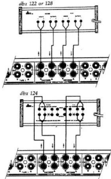
If you have a current dbx unit (222/4/8 or NX-40), study the appropriate hookup on the facing page; that's the easiest and fastest nomenclature to follow. Some non-dbx NR units (e.g., the old Advent Dolby ones) have similar labeling.
Do the same if you have a previous dbx NR unit (122/4/8). In the case of a 124, which is the most complicated, the hookup will go more easily if you designate jacks 1 and 2 as left and jacks 3 and 4 as right (red). Don't use the Record side's pairs of jacks numbered 2 and 4 or the Play side's pairs of jacks numbered 1 and 3; they're okay left empty (nothing plugged into them).
If you have some other non-dbx NR unit, it will help to figure out its encoder Ins and Outs and its decoder Ins and Outs. Often the former are called Record and the latter Play. Once you have figured this out, note that the 400 NR jacks are also labeled (from the rear) Out (To) and In (From) Encoder and Decoder. Connect the cables accordingly.
4 TAPE DECK 1,2,3. This, of course, is where you connect your decks -- cassette, open-reel, Beta/VHS hi-fi, or digital (processor plus VCR).
Connect the chosen 400 Tape Out to the Inputs of the deck or processor, and return its Output to the 400's Tape In (same one as going out, of course).

SOME TYPICAL HOOKUPS of dbx and other components with various labeling; also see
flowchart
graph TD
    A["4"] --> B["DBX NEWTON MA"]
    B --> C["3"]
    C --> D["2"]
    D --> E["1"]
    E --> F["1"]
    F --> G["1"]
    G --> H["1"]
    H --> I["1"]
    I --> J["1"]
    J --> K["1"]
    K --> L["1"]
    L --> M["1"]
    M --> N["1"]
    N --> O["1"]
    O --> P["1"]
    P --> Q["1"]
    Q --> R["1"]
    R --> S["1"]
    S --> T["1"]
    T --> U["1"]
    U --> V["1"]
    V --> W["1"]
    W --> X["1"]
    X --> Y["1"]
    Y --> Z["1"]
    Z --> AA["1"]
    AA --> AB["1"]
    AB --> AC["1"]
    AC --> AD["1"]
    AD --> AE["1"]
    AE --> AF["1"]
    AF --> AG["1"]
    AG --> AH["1"]
    AH --> AI["1"]
    AI --> AJ["1"]
    AJ --> AK["1"]
    AK --> AL["1"]
    AL --> AM["1"]
    AM --> AN["1"]
    AN --> AO["1"]
    AO --> AP["1"]
    AP --> AQ["1"]
    AQ --> AR["1"]
    AR --> AS["1"]
    AS --> AT["1"]
    AT --> AU["1"]
    AU --> AV["1"]
    AV --> AW["1"]
    AW --> AX["1"]
    AX --> AY["1"]
    AY --> AZ["1"]
    AZ --> BA["1"]
    BA --> BB["1"]
    BB --> BC["1"]
    BC --> BD["1"]
    BD --> BE["1"]
    BE --> BF["1"]
    BF --> BG["1"]
    BG --> BH["1"]
    BH --> BI["1"]
    BI --> BJ["1"]
    BJ --> BK["1"]
    BK --> BL["1"]
    BL --> BM["1"]
    BM --> BN["1"]
    BN --> BO["1"]
    BO --> BP["1"]
    BP --> BQ["1"]

flowchart
graph TD
    A["DBX 222/224/228"] --> B["PRECAP OR RECOGNER"]
    A --> C["THE1000A"]
    A --> D["INOC000A"]
    A --> E["INOC000B"]
    B --> F["Input"]
    C --> G["Output"]
    D --> H["Inverter"]
    E --> I["Inverter"]
    F --> J["INOC000A"]
    G --> K["INOC000B"]
    H --> L["INOC000A"]
    I --> M["INOC000B"]

USAGE NOTES
To get the most out of the dbx model 400, you must give some thought to the order in which to connect your other equipment.
As mentioned earlier, the 400 will be most useful if it's in (one of) the tape-monitor loop(s) of your preamp. If yours has two tape loops, we recommend that the 400 go in the first, leaving the second free for the future. An alternative location for the 400 is in the so-called external-processor (EP) loop of certain preamps, although if you hook it up there you lose flexibility both in your preamp and in the 400.
Also as mentioned, to use the 400 in Tape 1 -- to get signal to and from it -- you will have to leave the Tape 1 switch (usually a button) in. However, if your preamp has those separate "Input Selector" and "Record Out" selection switches (knobs, usually), you must leave the unit's Input Selector knob (or tape-monitor switch) set to Tape 1 and use the Rec Out knob to choose the program source that you want to listen to and route through the 400. We emphasize this because the impulse of most people is the opposite.
Now. Once you've hooked up the 400, the order becomes important, because it affects what sound changes you can obtain. As noted, the model 400 sends the program signal through the (up to) three connected processors in order, 1 to 2 to 3. If the corresponding button is in, the processor in Sound Processor (SP) loop 1 gets the signal first, after which it's passed to the processor in loop 2, and so on. If the button is disengaged or left out, naturally, the signal bypasses that loop and proceeds to the next.
If a processor has its own tape-monitor loop, of course, hookups of more than three are entirely possible. And if one of the initial three has a Pre/Post switch, that's the place to put a fourth unit for maximum flexibility: you can experiment with switching it before and after the processor with Pre/Post.
Since it's impossible to suggest a "perfect" order for all signal processors, we must emphasize that this section contains guidelines only. Your own good judgment is called for in any complex arrangement of your stereo system. Careful experimentation with various combinations and sequences of hookups will enable you to find out what works best.
Equalizers
User-controlled "graphic" equalizers (EQs) — commonly having one-octave nominal filter settings — are employed by some people as much to change the sound of the musical program as to correct for large irregularities in the response of the speakers and room. This kind of equalization is perhaps the most basic sound processing to be done, so if you follow the practice, your equalizer should be placed early on in the 400's signal path, probably in SP loop 1.
However, there are automatic equalizers -- the dbx 10/20 and 20/20, for example -- whose job is to make the speakers and room flatter in combination. These should be put in the last processor loop, so that no further alterations of the signal take place, downstream from it. The reason for this is that these equalizers use a test signal to do their job, and if this signal gets changed, the automatic-equalization results won't be correct. Thus SP loop 3 is the best place for such an EQ. (If for some reason you find it most convenient after all to place a sound processor after an automatic equalizer, everything will be okay if you
make sure that that processor is out or bypassed during the equalization process.) The third category is equalizers that come with your speakers to improve their response, usually at one or both ends of the audio band (Allison, Bose, dbx, EV, McIntosh, etc.). Such a dedicated equalizer must do its work after the 400, making the final correction. It might be placed in a tape-monitor (Tape 2) or external-processor (EP, SP, etc.) loop, or it can be put between preamp and power amp if you have separates. (Follow the manufacturer's directions.) This advice also pertains to narrow-band parametric or third-octave equalizers used only for changing speaker response and usually left to one setting.
Another solution for this is to put the 400 "inside" the speaker equalizer, in its tape-monitor loop. Your preamp's Tape Out goes to the speaker EQ's Line In (or From Preamp Tape Out), and the EQ's Line Out (or To Preamp Tape In) returns to the preamp's Tape In. Meanwhile, the EQ's Tape Out (or To Tape Recorder In) goes to the 400's Line:In, and the 400's Line:Out returns to the EQ's Tape In (or From Tape Recorder Out). Note that the speaker EQ itself is always set to its Tape Monitor.
Bass Reinforcers
A subharmonic synthesizer -- the dbx 120 or its predecessors (the 100, 110, 500) -- should follow a user-controlled program-source equalizer, so that deficiencies in the recording or broadcast can be somewhat corrected before the synthesizer gets the signal. In other words, the subharmonic synthesizer should have the best possible signal to work with.
However, an automatic equalizer (the dbx 10/20 or 20/20) or other EQ used principally to equalize speakers should come after a 120. The reason for this is that the low frequencies created by the synthesizer will then be reproduced by the smoothed-out system, and the synthesizer won't have to operate on a signal already modified for room/speaker irregularities. Likewise, other components that process the bass as well as boost it should be placed after a program EQ but before an automatic EQ.
Dynamic-Range Expanders and the like
Expanders, such as a dbx 1BX Series Two, 3BX Series Two, or 4BX (or their predecessors), and compressor/expander/enhancers, such as the previous dbx models 117/8/9, also should be located after program-source EQ and before automatic EQ. The reasoning is similar to that for bass processors. One, dynamic-range expanders should have as "correct" (in frequency response) a signal as possible to work with. A second reason is that dbx expanders, at least, provide some noise reduction (when they make soft sounds softer they also push down the noise floor several dB). Therefore they will make equalizers quieter, which sometimes is desirable because many of them aren't quite as low in noise as they could be.
In this sequence, some combinations of EQ settings, expanders, and program material may occasionally result in "surging" in the sound at various frequencies. Feel free to switch the order of equalizer and expander to see if there's an improvement.
Finally, if you own both an expander and a bass reinforcer, we recommend the expander be first.
Imagers
These are the devices that alter the stereo image -- its depth and width. They are best placed after everything in the sound-processing chain except
automatic equalizers like the dbx 20/20. Imagers do their job by modifying the phase and phase relationships in the program signal, so they must have close to the last say in changing the sound. The reason the dbx 20/20 can be placed afterward is that it equalizes both channels identically, doing no harm to the phase relationships between them. Note that the dbx 10/20 can equalize the channels either together (identically) or separately (differently), and may follow an imager only if used in the former mode. But imagers still are followed by dedicated speaker equalizers, of course.
Reverb Units
Like imagers, reverb devices should go toward the very end, after everything else but automatic EQs like the dbx 20/20.
Playing (Decoding) dbx Records...
You can play dbx-encoded records with any of the previous dbx 122/4/8 or the current 220 series (or NX-40) noise-reduction units, or you can use just the model 21 disc/tape decoder. The hookup and the operation of switches depend on the unit. Your preamp is set to Phono and Tape 1 (if that's where the 400 is).
... with a Model 122, 124, 128, or 222, 224, 228, or NX-40
If you have one of these encode/decode units, it should be connected in the model 400'a Noise Reduction Unit loop, as discussed earlier. To play a dbx record, the 400's SP buttons may be as you desire; the Post button must be in (so that the encoded record signal doesn't get tampered with by any of the signal processors); any one of the three Tape buttons must be in; and both the Decode and the Encode buttons must be in. Everything downstream from these buttons should be out.
Then set the dbx unit for disc decoding according to its instructions. Further signal processing, if selected, takes place as usual, after the record is decoded.
... with a Model 21
A dbx model 21 disc/tape decoder, too; can be placed in the 400's Noise Reduction loop, as noted. In this location the 21 can be used to play back dbx-encoded tapes as well as dbx records. To play the records, the 400's Post button must be pushed in and one of its Tape buttons must be pushed in. The model 21, for its part, must have its In/Out button pushed In and its Monitor:Tape/Source button disengaged (at Source). (For a tape, of course, the second button is pushed in, to Tape.)
If you want to use your 21 for dbx-record decoding only (and/or the 400's Noise Reduction loop is occupied with some other NR unit), it may go in the first SP loop -- and only the first. In this case, connect the 400's SP:Out jacks to the 21's Record:Inputs:From Preamp Tape Output, and the 21's Play:Outputs:To Preamp Tape or Monitor Input jacks return to the 400's SP:In. Leave the 21's four other (two sets of two) jacks alone. Returning to the front, the 21 should be left in Source with the noise-reduction button In.
To play a dbx record now, the 400's Line button is pushed in, the SP:1 button is pushed in, too, naturally, and the Post button is in. You can play dbx-encoded cassettes this way as well.
With this setup, tapes of dbx-encoded records will be recorded encoded, to
be decoded on playback. To tape a dbx record in decoded form (to make a Dolby copy, for example), push Pre.
... Through a Cassette Deck with dbx Noise Reduction
All but a few cassette decks with dbx noise reduction offer record-decoding capability, too. To take advantage of this feature when the deck is hooked up in one of the 400's tape loops, set the Sound Processors to Post, the Monitor to the deck's loop number, and leave Decode/Encode and all the Rec Selector buttons out.
Now follow the instructions in your cassette deck's owner's manual for playing dbx records. (Don't forget to turn up the deck's recording-level control; if it's all the way down, you won't hear the record.) You may, of course, use the sound processors (in Post) connected to the 400 as usual.
Second Noise-Reduction Units
If you wish to use a second noise-reduction unit (say, an outboard Dolby B) in the 400's Noise Reduction Unit loop, it should go in the dbx unit's tape-recorder loop. The dbx unit's To Tape Recorder Input (or equivalent) jacks go to the second unit's From Preamp (Tape) Out(put)/Line In(put)/From Tape Rec/To Amp Rec Out jacks, and its To Preamp (Tape) In(put)/Line Out(put)/To Tape Play/To Amp Tape (Monitor) In returns to the dbx unit's From Tape Recorder Output or equivalent. The second unit's To Tape Record(er) In(put)/To Tape/Tape Rec Out or equivalently named jacks go to the 400's Encoder:In, and its Decoder:Out jacks return to the second unit's From Tape Record(er) Out(put)/From Tape/Tape Play In or whatever. See below; it's easier.

flowchart
graph TD
    A["DBX"] --> B["DBX NOISE REDUCTION UNIT"]
    B --> C["ENCODER"]
    B --> D["NOISE REDUCTION UNIT"]
    C --> E["PLEAP OR RECEIVER"]
    C --> F["TAPE RECOORDS"]
    D --> G["PLEAP OR RECEIVER"]
    D --> H["TAPE RECOORDS"]
    E --> I["PLEAP PLEAP TARE OUTPUT"]
    F --> J["PLEAP PLEAP TARE OUTPUT"]
    G --> K["PLEAP PLEAP TARE OUTPUT"]
    H --> L["PLEAP PLEAP TARE OUTPUT"]
    I --> M["DOLOBY B OR OTHER"]
    J --> M
    K --> M
    L --> M
    M --> N["TO TARE RECOORDER OUTPUT RECORDER INPUT"]
When using dbx noise reduction, it generally is best to switch the other system out, and vice versa.
For more help with other units' nomenclature, see the section on rear-jack connections and following.
One-Way ("Single-Ended," "One-Pass") Noise-Reduction Units
A noise-reduction unit that works on playback only, to decrease the sound of record pops, clicks, scratches etc. or to reduce steadier noise in sources that aren't encoded, should be placed in the next SP loop on the 400 after a dbx record decoder (if you're using one). In any event, it should be early on in the sequence.
Other Processors
Some users might want to put a second preamp in one of the 400's SP loops because it has a useful filter or two, different tone controls, channel blending for headphone listening, etc. You will want to experiment about where to put it yet not go against guidelines already given. That is, locate it after record decoders and user-controlled EQs and before bass reinforcers, expanders, and automatic EQs. Similarly all other processors: experiment with care, while following any advice in the accompanying instruction manuals.
Four-Channel ("Quad"), Ambience-Recovery, Time-Delay Systems, etc.
The 400 is a stereo (two-channel) component. Rear-speaker processors and the like cannot easily be routed through a single 400; it's best to do these extra-channel hookups after the signal processing that takes place via the 400. With more than one 400 or a 400 and a 200, it is possible to do multi-channel routing -- but the switching gets extremely complicated.
Using 400 Loops as Extra Inputs
The 400's six sound-processor and tape loops can be used as extra inputs if your preamp doesn't have enough of its own. This may well be the case if you have new video, digital/VCR, and/or CD player sources. Note that playback sources will plug directly into the particular "In (from)" inputs on the back of the 400, with no cables returning to the component from the loop's "Out (to)" jacks.
Using the Pre Button
A warning is in order about pushing in the Pre button, placing the sound processors you have hooked up to the 400 in front of your tape decks. All recorders -- especially cassette decks, and even the very best of those -- can be readily overloaded by too much boosting of a given frequency, particularly in the treble. Reinforcing the bass (particularly, synthesizing subharmonic frequencies) when strong bass is already present, or expanding the dynamic range of material that has wide dynamics to begin with, also will saturate even the newest tapes and cassette desks. And using dbx noise reduction in taping will not prevent this. Always go easy in processing signals before taping.
If a program signal is sonically deficient in its original form — a dull orchestral broadcast, a heavily compressed FM station, an unbalanced tape, an old record with weak bass — then careful use of processors during taping may allow tapes to be made that sound cleaner, wider, and better-balanced than the original. But source material that is reasonably good to begin with in these respects — that's clear, quiet, dynamic and/or well-balanced — is best recorded straight, without Pre processing.
Remember that any improvements which seem necessary can always be added during playback.
Overdriving
Like tape decks, successive sound processors (ones coming after) can be overdriven by too much voltage. Most dbx equipment is capable of accepting large input levels without distress, and by its very nature, most dbx equipment can produce more signal at its output than it received. This is also true of equalizers when set to boost any frequencies and of spare preamps when their volume controls are set past unity gain. Therefore it's a good idea to pay attention to the maximum input-voltage capacity of all equipment downstream from each processor, and to consider moving up earlier any units that appear
relatively easier to overdrive. One symptom is harsh, grating distortion in the sound. Reduce the outputs of earlier processors and begin thinking about rearranging the order of the units.
A final caution: whenever you rearrange processors (or other equipment), be sure that all volume controls are all the way down and that everything is turned off. After reconnections are made and the units are turned back on, turn the volume controls back up slowly, to allow yourself time to react before doing damage to equipment connected to the 400, to amplifiers, to speakers (especially speakers) — or to your ears.
BLOCK DIAGRAM


flowchart
graph TD
    A["LINE IN"] --> B["SOUND PROCESSOR"]
    B --> C["PRE POST COPY"]
    C --> D["TAPE DECK PLAY"]
    D --> E["TAPE 1 TAPE 2 TAPE 3"]
    E --> F["TAPE 1 TAPE 2 TAPE 3"]
    F --> G["TAPE 1 TAPE 2 TAPE 3"]
    G --> H["TAPE 1 TAPE 2 TAPE 3"]
    H --> I["TAPE 1 TAPE 2 TAPE 3"]
    I --> J["TAPE 1 TAPE 2 TAPE 3"]
    J --> K["TAPE 1 TAPE 2 TAPE 3"]
    K --> L["TAPE 1 TAPE 2 TAPE 3"]
    L --> M["TAPE 1 TAPE 2 TAPE 3"]
    M --> N["TAPE 1 TAPE 2 TAPE 3"]
    N --> O["TAPE 1 TAPE 2 TAPE 3"]
    O --> P["TAPE 1 TAPE 2 TAPE 3"]
    P --> Q["TAPE 1 TAPE 2 TAPE 3"]
    Q --> R["TAPE 1 TAPE 2 TAPE 3"]
    R --> S["TAPE 1 TAPE 2 TAPE 3"]
    S --> T["TAPE 1 TAPE 2 TAPE 3"]
    T --> U["TAPE 1 TAPE 2 TAPE 3"]
    U --> V["TAPE 1 TAPE 2 TAPE 3"]
    V --> W["TAPE 1 TAPE 2 TAPE 3"]
    W --> X["TAPE 1 TAPE 2 TAPE 3"]
    X --> Y["TAPE 1 TAPE 2 TAPE 3"]
    Y --> Z["TAPE 1 TAPE 2 TAPE 3"]
    Z --> AA["TAPE 1 TAPE 2 TAPE 3"]
    AA --> AB["TAPE 1 TAPE 2 TAPE 3"]
    AB --> AC["TAPE 1 TAPE 2 TAPE 3"]
    AC --> AD["TAPE 1 TAPE 2 TAPE 3"]
    AD --> AE["TAPE 1 TAPE 2 TAPE 3"]
    AE --> AF["TAPE 1 TAPE 2 TAPE 3"]
    AF --> AG["TAPE 1 TAPE 2 TAPE 3"]
    AG --> AH["TAPE 1 TAPE 2 TAPE 3"]
    AH --> AI["TAPE 1 TAPE 2 TAPE 3"]
    AI --> AJ["TAPE 1 TAPE 2 TAPE 3"]
    AJ --> AK["TAPE 1 TAPE 2 TAPE 3"]
    AK --> AL["TAPE 1 TAPE 2 TAPE 3"]
    AL --> AM["TAPE 1 TAPE 2 TAPE 3"]
    AM --> AN["TAPE 1 TAPE 2 TAPE 3"]
    AN --> AO["TAPE 1 TAPE 2 TAPE 3"]
    AO --> AP["TAPE 1 TAPE 2 TAPE 3"]
    AP --> AQ["TAPE 1 TAPE 2 TAPE 3"]
    AQ --> AR["TAPE 1 TAPE 2 TAPE 3"]
    AR --> AS["TAPE 1 TAPE 2 TAPE 3"]
    AS --> AT["TAPE 1 TAPE 2 TAPE 3"]
    AT --> AU["TAPE 1 TAPE 2 TAPE 3"]
    AU --> AV["TAPE 1 TAPE 2 TAPE 3"]
    AV --> AW["TAPE 1 TAPE 2 TAPE 3"]
    AW --> AX["TAPE 1 TAPE 2 TAPE 3"]
    AX --> AY["TAPE 1 TAPE 2 TAPE 3"]
    AY --> AZ["TAPE 1 TAPE 2 TAPE 3"]
    AZ --> BA["TAPE 1 TAPE 2 TAPE 3"]
    BA --> BB["TAPE 1 TAPE 2 TAPE 3"]
    BB --> BC["TAPE 1 TAPE 2 TAPE 3"]
    BC --> BD["TAPE 1 TAPE 2 TAPE 3"]
    BD --> BE["TAPE 1 TAPE 2 TAPE 3"]
    BE --> BF["TAPE 1 TAPE 2 TAPE 3"]
    BF --> BG["TAPE 1 TAPE 2 TAPE 3"]
    BG --> BH["TAPE 1 TAPE 2 TAPE 3"]
    BH --> BI["TAPE 1 TAPE 2 TAPE 3"]
    BI --> BJ["TAPE 1 TAPE 2 TAPE 3"]
    BJ --> BK["TAPE 1 TAPE 2 TAPE 3"]
    BK --> BL["TAPE 1 TAPE 2 TAPE 3"]
    BL --> BM["TAPE 1 TAPE 2 TAPE 3"]
    BM --> BN["TAPE 1 TAPE 2 TAPE 3"]
    BN --> BO["TAPE 1 TAPE 2 TAPE 3"]
    BO --> BP["TAPE 1 TAPE 2 TAPE 3"]
    BP --> BQ["TAPE 1 TAPE 2 TAPE 3"]
    BQ --> BR["TAPE 1 TAPE 2 TAPE 3"]
    BR --> BS["TAPE 1 TAPE 2 TAPE 3"]
    BS --> BT["TAPE 1 TAPE 2 TAPE 3"]
    BT --> BU["TAPE 1 TAPE 2 TAPE 3"]
    BU --> BV["TAPE 1 TAPE 2 TAPE 3"]
    BV --> BW["TAPE 1 TAPE 2 TAPE 3"]
SCHEMATIC

WARRANTY and FACTORY SERVICE
All dbx products are covered by a limited warranty; for details, consult your warranty/registration card or your dealer.
The dbx Customer Service Dept. will help you use this product. For answers to questions and information on problems, write to:
dbx Inc.
71 Chapel St.
Box 100C
Newton, Mass. 02195 USA
Attn: Customer Service
You also may call (617) 964-3210 during business hours (Eastern time). The Telex is 92-2522.
Should it become necessary to have your equipment serviced, call this toll-free number to get a Return Authorization: 1-800-323-4353. No units will be accepted without this authorization. After you have your return authorization, repack the unit, including a note with your name, address, phone number, and a description of the problem. Send the unit freight prepaid to the address given at the 800 number. (Continue to send inquiries to the Customer Service Dept., however.)
We strongly recommend that you insure the package and send it by United Parcel Service.
If you live outside the USA, contact your dbx dealer for the address of the nearest authorized repair center.
FOR USERS IN THE UNITED KINGDOM
Important
The wires in this mains lead are coloured in accordance with the following code:
Blue: Neutral
Brown: Live.
As the colours of the wires in the mains lead of this apparatus may not correspond with the coloured markings identifying the terminals in your plug, proceed as follows:
The wire that is coloured blue must be connected to the terminal that is marked with the letter N or coloured black;
The wire that is coloured brown must be connected to the terminal that is marked with the letter L or coloured red.
Ensure that all terminals are securely tightened and that there are no loose strands of wire.
Warning
This unit must be protected by a 3-amp fuse, preferably using a fused plug.
Also, do not remove the cover without first disconnecting the unit from the mains supply.
For Information and Service
Please write to: Harman UK Ltd.
Mill St.
Slough
SL2 5DD
Berkshire, England
The telephone is 0753 769 11.
- INSPECTION and INSTALLATION
- CONTENTS
- READ THIS FIRST
- FRONT PANEL
- AC LINE VOLTAGE REQUIREMENT INDICATOR
- AC POWER CABLE
- USAGE NOTES
- Equalizers
- Bass Reinforcers
- Dynamic-Range Expanders and the like
- Imagers
- Reverb Units
- Playing (Decoding) dbx Records...
- ... with a Model 21
- ... Through a Cassette Deck with dbx Noise Reduction
- Second Noise-Reduction Units
- One-Way ("Single-Ended," "One-Pass") Noise-Reduction Units
- Other Processors
- Four-Channel ("Quad"), Ambience-Recovery, Time-Delay Systems, etc.
- Using 400 Loops as Extra Inputs
- Using the Pre Button
- Overdriving
- BLOCK DIAGRAM
- SCHEMATIC
- WARRANTY and FACTORY SERVICE
- FOR USERS IN THE UNITED KINGDOM
- Important
- Warning
- For Information and Service
Marke : DBX
Modell : 400
Kategorie : Professionelle Audioausrüstung