
760X - Audioverstärker DBX - Kostenlose Bedienungsanleitung
Finden Sie kostenlos die Bedienungsanleitung des Geräts 760X DBX als PDF.


| Produkttyp | Mikrofonvorverstärker |
| Marke | DBX |
| Modell | 760X |
| Kanäle | 2 |
| Frequenzgang | 20 Hz - 20 kHz, +0/-0,15 dB |
| Eingangsimpedanz | ≥ 2 kΩ |
| Maximaler Eingangspegel | 0,7 V RMS |
| Ausgangsimpedanz | 30 Ω, elektronisch symmetrisch und floatend |
| Maximaler Ausgangspegel (symmetrisch) | +23,5 dBu an 600 Ω |
| Anschlüsse | XLR (sym. Ein-/Ausgänge), 1/4" Klinke (unsym. Ausgang) |
| Klirrfaktor (THD) | ≤ 0,01 % (typ. 0,006 %) |
| SMPTE Intermodulation | ≤ 0,02 % |
| Äquivalenter Eingangsrauschpegel | < -129,5 dBu (bez. auf 150 Ω) |
| Verstärkungsbereich | ca. +20 dB bis +60 dB |
| Phantomspeisung | +48 V DC über 6,81 kΩ Widerstände |
| Stromversorgung | Externes Netzteil (18 V AC) |
| Betriebstemperatur | 0 °C bis 45 °C |
| Abmessungen (H x B x T) | 4,5 cm x 21,6 cm x 18,4 cm |
| Gewicht (netto) | 1,36 kg |
| Gehäuse | Halbe 19-Zoll-Baugruppe, 1 HE |
| Garantie | 2 Jahre Standardgarantie |
| Bedienelemente pro Kanal | Gain-Regler, CLIP-LED, Polaritätsschalter, Phantomspeiseschalter |
| Besonderheiten | Transformatorlose Schaltung, servo-symmetrierte Ausgänge, CLIP-Anzeige ab 10 μs |
| Sicherheit | Keine vom Benutzer zu wartenden Teile; Gerät vor Feuchtigkeit schützen; bei Gewitter Netzstecker ziehen |
| Reinigung | Mit trockenem Tuch reinigen; keine Flüssigkeiten in das Gerät gelangen lassen |
Häufig gestellte Fragen - 760X DBX
Benutzerfragen zu 760X DBX
0 Frage zu diesem Gerät. Beantworten Sie die, die Sie kennen, oder stellen Sie Ihre eigene.
Eine neue Frage zu diesem Gerät stellen
Laden Sie die Anleitung für Ihr Audioverstärker kostenlos im PDF-Format! Finden Sie Ihr Handbuch 760X - DBX und nehmen Sie Ihr elektronisches Gerät wieder in die Hand. Auf dieser Seite sind alle Dokumente veröffentlicht, die für die Verwendung Ihres Geräts notwendig sind. 760X von der Marke DBX.
BEDIENUNGSANLEITUNG 760X DBX
MODEL 760X
MICROPHONE PREAMPLIFIER

OPERATION MANUAL
This Manual is part number 18-2035-B
© Copyright 1995 by dbx Professional Products

dbx Professional Products
8760 South Sandy Parkway, Sandy, UT 84070
Telephone (801) 568-7660 Fax (801) 568-7662

CAUTION
RISK OF ELECTRIC SHOCK DO NOT OPEN

ATTENTION: RISQUE DE CHOC ELECTRIQUE - NE PAS OUVRIR
WARNING: TO REDUCE THE RISK OF FIRE OR ELECTRIC SHOCK DO NOT EXPOSE THIS EQUIPMENT TO RAIN OR MOISTURE
The symbols shown at left are internationally accepted symbols that warn of potential hazards with electrical products. The lightning flash with arrowpoint in an equilateral triangle means that there are dangerous voltages present within the unit. The exclamation point in an equilateral triangle indicates that it is necessary for the user to refer to the owner's manual.
These symbols warn that there are no user serviceable parts inside the unit. Do not open the unit. Do not attempt to service the unit yourself. Refer all servicing to qualified personnel. Opening the chassis for any reason will void the manufacturer's warranty. Do not get the unit wet. If liquid is spilled on the unit, shut it off immediately and take it to a dealer for service. Disconnect the unit during storms to prevent damage.
U.K. MAINS PLUG WARNING
A moulded mains plug that has been cut off from the cord is unsafe. Discard the mains plug at a suitable disposal facility. NEVER UNDER ANY CIRCUM-STANCES SHOULD YOU INSERT A DAMAGED OR CUT MAINS PLUG INTO A 13 AMP POWER SOCKET. Do not use the mains plug without the fuse cover in place. Replacement fuse covers can be obtained from your local retailer. Replacement fuses are 13 amps and MUST be ASTA approved to BS1362.
SAFETY INSTRUCTIONS (EUROPEAN)
NOTICE FOR CUSTOMERS IF YOUR UNIT IS EQUIPPED WITH A POWER CORD.
WARNING: THIS APPLIANCE MUST BE EARTHED.
The cores in the mains lead are coloured in accordance with the following code:
GREEN and YELLOW - Earth
BLUE - Neutral
BROWN - Live
As colours of the cores in the mains lead of this appliance may not correspond with the coloured markings identifying the terminals in your plug, proceed as follows:
• The core which is coloured green and yellow must be connected to the terminal in the plug marked with the letter E, or with the earth symbol, or coloured green, or green and yellow.
- The core which is coloured blue must be connected to the terminal marked N or coloured black.
• The core which is coloured brown must be connected to the terminal marked L or coloured red.
The power cord is terminated in a CEE7/7 plug (Continental Europe). The green/yellow wire is connected directly to the unit's chassis. If you need to change the plug, and if you are qualified to do so, refer to the table below.
| CONDUCTOR | WIRE COLOR | ||
| Normal | Alt | ||
| L | LIVE | BROWN | BLACK |
| N | NEUTRAL | BLUE | WHITE |
| E | EARTH GND | GREEN/YEL | GREEN |
WARNING: If the ground is defeated, certain fault conditions in the unit or in the system to which it is connected can result in full line voltage between chassis and earth ground. Severe injury or death can then result if the chassis and earth ground are touched simultaneously.
IMPORTANT!
FOR YOUR PROTECTION, PLEASE READ THE FOLLOWING:
WATER AND MOISTURE: Appliance should not be used near water (e.g. near a bathtub, washbowl, kitchen sink, laundry tub, in a wet basement, or near a swimming pool, etc). Care should be taken so that objects do not fall and liquids are not spilled into the enclosure through openings.
POWER SOURCES: The appliance should be connected to a power supply only of the type described in the operating instructions or as marked on the appliance.
GROUNDING OR POLARIZATION: Precautions should be taken so that the grounding or polarization means of an appliance is not defeated.
POWER CORD PROTECTION: Power supply cords should be routed so that they are not likely to be walked on or pinched by items placed upon or against them, paying particular attention to cords at plugs, convenience receptacles, and the point where they exit from the appliance.
SERVICING: The user should not attempt to service the appliance beyond that described in the operating instructions. All other servicing should be referred to qualified service personnel.
QUICK SETUP
To get your unit up and running as quickly as possible, do the following steps. For more detailed information, refer to the specified pages.
□ Unpack and Inspect the 760X Package.
Page 1
□ Mount Unit in a Rack (OPTIONAL).
Page 6
□ Connect the Unit To Your System.
Page 4
☐ Set Levels and Controls as Needed.
Page 2
INSPECTION
- Verify that the 760X package contains the following:
☐ 760X Unit and External Power Supply
□ Accessory Kit (Rack Mounting Support)
☐ Operation Manual and Registration Card
INTRODUCTION
When you use a microphone to record vocals and acoustic instruments, make recordings to DAT, or sample acoustic sounds, you want the best definition and character possible from your microphone. The 760X is the perfect partner for your microphone, providing you with two channels of audio purist quality transformerless microphone preamplification. The 760X delivers up to 60dB of sonically transparent gain to reveal the detail and audio signature of even the most esoteric studio mics. It transforms their low level output signal to a high level, high current output for direct connection to the line level inputs of your mixer, DAT machine, sampler, or any other recording medium that accepts line level, analog input.
Polarity Reverse and Phantom Power switches complete the complement of professional microphone preamplifier controls, and the CLIP LED accurately indicates clipping as brief as 10μs in duration anywhere in the circuit. The inputs and outputs are protected from radio interference. The servo-balanced outputs electronically simulate a transformer-balanced output without the audio artifacts that transformers impose.
Your 760X may reveal nuances of sound previously masked by other equipment. This will affect your mix, mic placement, etc. For tips, techniques and tutorials, we recommend that you consult one of the many fine texts available that deal with sound recording (e.g., "Creative Recording 2," by Paul White; "Stereo Microphone Technique," by Bruce Bartlett; "Microphone Technology and Technique," by John Borwick).
Features
☐ Two channels of high performance microphone preamplification in a compact half-rack package
Floating, electronically balanced line level outputs provide consistent performance into a variety of loads ( 14 ” unbalanced outputs also provided)
□ CLIP indicators signal overload in any part of the circuitry
☐ Up to 60dB of gain in a low noise, sonically transparent circuit
Separate POLARITY REVERSE and PHANTOM POWER switches for each channel
OPERATING CONTROLS
Front Panel

POWER LED: This red LED indicates that the 760X is connected to AC power.
Note: To reduce the risk of damage to your system, set the GAIN control to minimum (fully counterclockwise) and lower your playback monitor levels before you connect a microphone, power on the unit, or press the PHANTOM or POLARITY switches. This will eliminate spikes and surges, acoustical feedback, loud pops, momentary hiss, or other unwanted sounds.
MICROPHONE 1 and MICROPHONE 2
GAIN Control and CLIP LED: For each microphone channel, use this control to set the level of gain added to the microphone input signal, thereby defining the 760X's output level. Try to set the GAIN control so that you do not have to reset it repeatedly; allow headroom for the maximum expected mic levels. The 760X can provide 20dB to 60dB of gain.
Note: To get the lowest noise possible from the 760X, set the input attenuators (if any) on your recorder or mixer for nominal levels (often about 34 of the way up; refer to the device's operating manual). Then, set the 760's GAIN so that your recorder or mixer is at its optimal operating level.
The red CLIP LED indicates that the combination of the mic signal and additional gain exceeds the circuits' capabilities; reduce gain via the GAIN control. Set the GAIN control so that the CLIP LED never lights. If the meters on your load device (e.g., tape recorder, mixer, etc.) are in the red and your CLIP LED is not lit, simply reduce the 760X's gain until the desired levels are obtained. If your load device is still in the red, reduce its input attenuators (if available).
POLARITY Switch and REVERSE LED: When this switch is out and the REVERSE LED is not lit, the polarity of the signal at the 760X's input matches the polarity of the signal at the 760X's output and is "in phase" (i.e., a positive signal on pin 2 of the input results in a positive signal on pin 2 of the output). To set the 760X's input and output to be "out of phase" with each other, press the POLARITY switch so that the REVERSE LED is lit. In this case, the positive and negative signals on pins 2 and 3 of the input are reversed on the outputs. For more information on specific applications using microphone polarity, consult one of the sound recording text listed in the Introduction.
PHANTOM Power Switch and +48V LED: When you use phantom powered mics with your 760X, press the PHANTOM power switch so that the +48V LED lights. This activates the 760's phantom power, providing 48VDC to the microphone through its connecting cable. This industry-standard configuration supports virtually all phantom powered mics. Note that some mics may take several seconds to fully power up when phantom power is applied. If you are using mics that do not require phantom power, press the switch so that the +48VDC LED is not lit.
Note: Always plug in a condenser mic with PHANTOM power off and gain levels down. Then switch the PHANTOM power on and adjust the gain as needed.
Rear Panel

INPUT Jacks (BALANCED): The INPUT jacks accept either balanced or unbalanced signals through XLR connectors. Pins 2 and 3 are symmetrically balanced and floating; thus, either can be used as "HOT" without difficulty. Pin 1 is connected to the 760X chassis ground. Nominal input level is -60dBu to -20dBu. Clipping level is 0dBu.
OUTPUT Jacks (BALANCED): The 760X's (BALANCED) OUTPUT jacks are driven by floating active-balanced amplifiers that simulate a true transformer output. This permits the load at the output to be either balanced with respect to ground, or single-ended to ground (unbalanced) with very little difference (dB) in output level. Either pin 2 or 3 can be grounded in this manner.
The outputs jacks accept XLR-type connectors. Pins 2 and 3 are symmetrically balanced and floating; thus either can be used as "HOT" without difficulty. Pin 1 is chassis ground. Nominal output signal level is +4dBu into 600Ω, and typical maximum output signal level is +20dBu (unbalanced) or +23.5dBu (balanced) into 600Ω.
Although it is not standard practice, the 760X is capable of driving balanced and unbalanced signals simultaneously.
OUTPUT Jacks (UNBALANCED): The 760X's (UNBALANCED) OUTPUT jacks accept 1/4" phone plugs. Nominal output signal level is +4dBu and typical maximum output signal level is +20dBu. The outputs are single-ended, Tip HOT. (Note: This output is not designed to drive a 600Ω load.)
AC Power Supply Jack: Plug the AC Power Supply Adapter (shipped with your unit) into this jack and an appropriate AC power source. Note that the 760X does not have a power button. It is recommended that the 760X be "On" at all times. Power consumption is low. If you do not plan to use the 760X for an extended period of time, unplug it. Remember to reduce your playback levels at the power amp whenever connecting or powering equipment on or off.
WARNING: Be sure to verify your actual line voltage, as indicated on the external power supply. Connection to an inappropriate power supply or power source may result in extensive damage which is not covered by the warranty.

CONNECTING THE 760X TO YOUR SYSTEM
Basic Connection
The 760X accepts any low level microphone signal and can be connected to a variety of audio loads (e.g., mixer, analog tape recorder, hard disk or DAT recorder, sampler). The 760X can support up to two microphone lines. For specific rack mounting and cabling information, refer to the following pages.
For all connections, refer to the following steps:

- Turn Off all equipment before making any connections.
- Make connections via XLR jacks or 1/4" phone jacks according to your requirements.
- Connect the 760X AC power supply to the 760X POWER jack and an appropriate AC power source to power on the unit.
Note: We recommend you always power on the unit with the GAIN control set to minimum (fully counterclockwise). This will help in safeguarding your system against sudden spikes and surges, as well as possible acoustical feedback if microphones are connected and left "open."
Note: Check the line voltage (printed on the power supply) and verify that it is correct.

flowchart
graph LR
    A["MIC"] -->|OUTPUT| B["760X REAR PANEL"]
    B -->|INPUT| C["MIXER, ANALOG TAPE RECORDER, HARD DISK OR DAT RECORDER, SAMPLER"]
    B -->|OUTPUT| D["DBX PROFESSIONAL PRODUCTS"]
    D --> E["MODEL 760X"]
    E --> F["USE ONLY SPECIFIED POWER SUPPLY 18-VAC"]
    style A fill:#f9f,stroke:#333
    style B fill:#ccf,stroke:#333
    style C fill:#cfc,stroke:#333
    style D fill:#fcc,stroke:#333
760X Basic Connection
INSTALLATION CONSIDERATIONS
Input/Output Cable
The 760X is designed for nominal microphone output levels (-60dBu to -20dBu) at its input jacks; +4dBu levels at its XLR output jacks, and +4dBu levels at its 14'' output phone jacks. Inputs can be used with either balanced or unbalanced microphones and outputs can be used with either balanced or unbalanced loads, provided you use proper cabling.
Use low impedance microphones or a high-to-low impedance matching transformer with a high impedance microphone.
Note: The 760X's XLR jacks can support balanced or unbalanced signals. The 760X's phone jacks can only support unbalanced signals.
A balanced line is defined as two-conductor shielded cable with the two center conductors carrying equal send and return currents. An unbalanced line is generally a single-conductor shielded cable with the center conductor carrying the signal and the shield at ground potential.
The XLR input connectors are in phase with the XLR output connectors. Because inputs and outputs are balanced, and are in-phase (unless the REVERSE LED is lit), either pin 2 or 3 can be used as "HOT."
Input Cable Configuration
The XLR input connectors on the 760X can be driven with either balanced or unbalanced signal lines up to 0dBu maximum with excellent results. The input impedance is greater than 2kΩ.
Output Cable Configurations
The (BALANCED) OUTPUT connectors of the 760X can drive either balanced or unbalanced lines with excellent results. Typical driving capability is +23.5dBu into a balanced 600Ω load, and +21dBu into an unbalanced 10kΩ load. In either case, output impedance is 30Ω. Due to the floating characteristic of the active electronic output amplifiers, it is unnecessary to use transformers at the outputs.
The 760X's (UNBALANCED) OUTPUT connectors will drive either balanced or unbalanced loads through 14 " phone plugs (Tip Hot), as long as the cables are wired accordingly. The unbalanced output is independent of the balanced output, so the 760X can drive balanced and unbalanced loads simultaneously.
Note: Most balanced (3-conductor) cables have the shield connected at both ends. This can result in ground loops which cause hum. If hum is a problem, try disconnecting the shield on one or more of your cables, preferably at the input of the driven device, not at the 760X's output. The shield is pin 1 on the XLR, sleeve on a 14 " TRS.
(Because the 760X is not normally connected to the power line ground, ground loops are unlikely unless the two outputs are connected to different devices, or if the shield of the mic cable is connected to a system or power ground.)

Non-Standard Output Connections
Mounting the 760X in a 1U Rack Space
The 760X requires one rack space (height) and half rack space (width). It can be mounted above or below anything that doesn't generate excessive heat, since it requires no special ventilation. Ambient temperatures should not exceed 113°F (45°C) when equipment is powered. Hardware for mounting your 760X is provided in the Accessory Kit included in your 760X package.
Two 760X units can be mounted side-by-side in one rack space. The following dbx half-rack processors can be mounted next to the 760X to save rack space: 1024 Buffer Amplifier, 163X Compressor/Limiter, 263X De-Esser, 363X Dual Noise Gate, 463X OverEasy™ Noise Gate, 563X Hiss Reducer, dbx 150X Type I or 140X Type II Noise Reduction. Hardware for side-by-side mounting is included with each half-rack product. If the rubber feet were previously installed, they should be removed at this time.

Caution: Never remove the cover. There are no user-serviceable parts inside, and you run the risk of an electric shock.
To install a single 760X (left or right side)
You will need: 1 blank black panel
1 rack ear
1 blank panel adapter piece
1 3/32" Allen wrench
1 Phillips screwdriver (not included)
4 pan head Phillips screws
2 hex head screws

Rack Mounting One Unit
Note: Your 760X Accessory Kit includes the tools and hardware listed above, except as noted.
A. Use a Phillips screwdriver to loosely attach the single rack ear to either side of the 760X with two pan head Phillips screws.
Note: If this is the first time the rack ear has been installed, you will be cutting threads as you drive the screws. This is normal.
B. Loosely attach the adapter piece to the other side of the 760X using two more pan head Phillips screws and a Phillips screwdriver. See note directly above.
C. Loosely attach the blank panel and adapter piece using an Allen wrench and two hex head screws.
D. Align everything on a flat surface and tighten the screws with a Phillips screwdriver and the hex wrench.
To install two units side-by-side
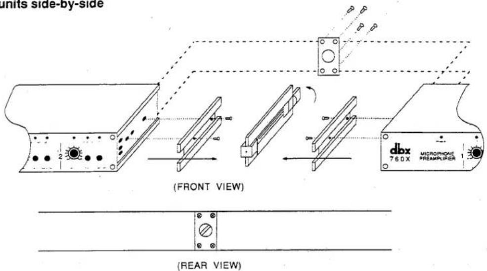
Rack Mounting Two Units
| You will need: | 1 | joiner assembly (joiner, joiner side pieces) |
| 1 | reinforcing plate | |
| 2 | rack ears | |
| 1 | 3/32 " Allen wrench | |
| 1 | Phillips screwdriver (not included) | |
| 4 | pan head Phillips screws | |
| 4 | flat head countersink screws |
Note: Your 760X Accessory Kit includes the tools and hardware listed above, except as noted.
A. Remove the joiner assembly from the Accessory Kit that was supplied with each unit. Note how the joiner side pieces are held together by the joiner before you separate them. This is important when it comes time to join the units together. Now separate the joiner side pieces from the joiner by turning the thumbscrew counterclockwise.
B. At this time you will need to designate a "Left" and a "Right" unit.
C. With the left unit facing you, loosely attach a rack ear to the left side of the unit with two pan head Phillips screws. On the right side of the unit, place a joiner side piece into the extruded channel so the holes in the unit align with the holes in the joiner side piece — countersink side up. Secure the joiner side piece with two countersink screws.
Note: If this is the first time the rack ear has been installed, you will be cutting threads as you drive the screws. This is normal.
D. Repeat step "C" with the "Right" unit; swapping right for left with regard to the rack ear mounting and left for right with regard to the joiner side piece mounting.
E. Place the Left and Right units on a flat surface, rear facing, so the joiner side pieces are approximately 2" apart. Take the joiner assembly and loosen the thumbscrew so the sliding catches clear the joiner side-piece cut-outs. Now place the joiner assembly against one of the units with the side piece so it lies flush. (The joiner assembly should be positioned so the thumbscrew is accessible from the rear of the unit.) While holding the joiner assembly in position,
slide the other unit over so it mates flush with the joiner assembly and turn the thumbscrew clockwise until it is snug. Do not over-tighten. Both units should now be secured together.
F. Make sure everything is aligned, and tighten the screws on each of the two rack ears.
Note: For installations where the two units will be subjected to physical stress (e.g. portable operations), a small OPTIONAL reinforcement plate is included. See steps G through I. If you do not wish to use the reinforcing plate, skip the following steps.
G. Turn the two units so that the back faces you. Remove the four rear cover screws nearest the joiner knob.
H. Place the reinforcing plate over the joiner knob so that the four screw holes line up.
I. Replace the four screws, using the slightly longer screws provided in the Accessory Kit.
Note: When mounting different models side by side, some variation in front panel depth is normal.
TECHNICAL SUPPORT, FACTORY SERVICE
Technical Support, Factory Service
The 760X is an all-solid-state product with components chosen for high performance and excellent reliability. Each 760X is tested, burned in and calibrated at the factory and should require no internal adjustment of any type throughout the life of the unit. We recommend that your 760X be returned to the factory only after referring to the manual and consulting with Customer Service.
Our phone number, fax number and address are listed on the inside front cover. When you contact Customer Service, be prepared to accurately describe the problem. Know the serial number of your unit — this is printed on a sticker attached to the rear panel.
Please refer to the terms of your Limited Two-Year Standard Warranty, which extends to the first end-user. After expiration of the warranty, a reasonable charge will be made for parts, labor, and packing if you choose to use the factory service facility. In all cases, you are responsible for transportation charges to the factory. dbx will pay return shipping if the unit is still under warranty.
Shipping Instructions: Use the original packing material if it is available. Mark the package with the name of the shipper, and with these words in red: DELICATE INSTRUMENT, FRAGILE! Insure the package properly. Ship prepaid, not collect. Do not ship parcel post.
Registration Card and User Feedback
We appreciate your feedback. After you have an opportunity to use your new 760X, please complete the Registration Card (located in the back of this manual), detach it from the manual and return it.
SCHEMATICS
Schematics for the 760X are provided on the following pages.
SPECIFICATIONS
Note: 0dBV = 1.0VRMS; 0dBu = 0.775VRMS
Specifications are subject to change.
| Frequency Response | 20Hz - 20kHz, +0, -0.15dB20Hz - 200kHz, +0, -3dB |
| Input Impedance | ≥2kΩ |
| Maximum Input Level | 0.7VRMS |
| Output Impedance | 30Ω, Electronically balanced and floating |
| Maximum Output Level | +23.5dBu into 600Ω (balanced) |
| Connector Type | XLR (Balanced Inputs and Outputs); 1⁄4" Phone Jack (Unbalanced Output) |
| THD | ≥0.01% (Typically 0.006%) 20Hz-20kHz; <50dB Gain, +10dB output |
| SMPTE Intermodulation Distortion | (60:7000Hz, 4:1) ≤0.02% |
| Equivalent Input Noise | <-129.5dBu, ref 150Ω |
| Gain Adjustment | approximately +20dB to +60dB |
| Phantom Power | +48VDC, applied to pins 2 and 3 of the input XLR connector through 6.81kΩ resistors. |
| Power Requirements | AC provided by external power supply included with unit. |
| Operating Temperature | 0°C to 45°C (32°F to 113°F) |
| Dimensions (H x W x D) | 1.75" x 8.5" x 7.25" (4.5cm x 21.6cm x 18.4cm) |
| Rack Space | 1 Rack Unit, Half Rack Design |
| Weight | Net Weight: 3 lbs (1.36 kg)Shipping Weight: 5.5 lbs (2.49 kg) |
| Warranty | dbx standard two-year warranty |

| dbx® |
| TITLE: SCHEMATIC760 MIC PREAMP61124-000-03 2 of 2 |

- MODEL 760X
- MICROPHONE PREAMPLIFIER
- CAUTION
- U.K. MAINS PLUG WARNING
- SAFETY INSTRUCTIONS (EUROPEAN)
- IMPORTANT!
- FOR YOUR PROTECTION, PLEASE READ THE FOLLOWING:
- QUICK SETUP
- INSPECTION
- INTRODUCTION
- Features
- OPERATING CONTROLS
- MICROPHONE 1 and MICROPHONE 2
- CONNECTING THE 760X TO YOUR SYSTEM
- Basic Connection
- INSTALLATION CONSIDERATIONS
- Input/Output Cable
- Input Cable Configuration
- Output Cable Configurations
- Mounting the 760X in a 1U Rack Space
- To install a single 760X (left or right side)
- Rack Mounting One Unit
- TECHNICAL SUPPORT, FACTORY SERVICE
- Registration Card and User Feedback
- SCHEMATICS
- SPECIFICATIONS
Marke : DBX
Modell : 760X
Kategorie : Audioverstärker