
WiMeter-S - Nicht kategorisiert Sungrow - Kostenlose Bedienungsanleitung
Finden Sie kostenlos die Bedienungsanleitung des Geräts WiMeter-S Sungrow als PDF.


| Produkttyp | Einphasiger drahtloser Energiezähler WiMeter-S |
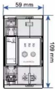
| Abmessungen (B x H x T) | 59 x 109 x 66 mm |
| Gewicht | 350 g |
| Stromversorgung | 220–240 V AC, maximale Leistungsaufnahme 2,5 W |
| Messbereich Spannung | 180–288 V AC |
| Messbereich Strom | 0–100 A |
| Messgenauigkeit Spannung/Strom/Leistung | ±0,5 % |
| Messgenauigkeit Energie | ±1 % |
| Kommunikation | WLAN (802.11 b/g/n), RS485-Schnittstelle |
| LED-Anzeigen | RUN (grün), COM (rot), NET (blau), PWR/COM (gelb), 1000 imp/kWh (rot) |
| Montage | DIN-Schiene (35 mm) |
| Schutzart | IP20 |
| Umgebungstemperatur | -30 °C bis 60 °C |
| Relative Luftfeuchtigkeit | ≤ 95 % (nicht kondensierend) |
| Maximale Betriebshöhe | ≤ 4000 m |
| Sicherheitshinweise | Nur für den Innenbereich; externer Trennschalter erforderlich; Hauptsicherung max. 100 A; nicht für Abrechnungszwecke |
| Wartung und Reinigung | Vor Reinigung vom Stromnetz trennen; nur mit trockenem Tuch reinigen |
| Lieferumfang | WiMeter-S, Antenne, Dokumente (Konformitätserklärung, Garantiekarte, Kurzanleitung) |
| Ersatzteile und Reparatur | Bei Beschädigung oder Fehlen von Teilen wenden Sie sich an SUNGROW oder den Händler. Keine eigenmächtigen Modifikationen. |
Häufig gestellte Fragen - WiMeter-S Sungrow
Benutzerfragen zu WiMeter-S Sungrow
0 Frage zu diesem Gerät. Beantworten Sie die, die Sie kennen, oder stellen Sie Ihre eigene.
Eine neue Frage zu diesem Gerät stellen
Laden Sie die Anleitung für Ihr Nicht kategorisiert kostenlos im PDF-Format! Finden Sie Ihr Handbuch WiMeter-S - Sungrow und nehmen Sie Ihr elektronisches Gerät wieder in die Hand. Auf dieser Seite sind alle Dokumente veröffentlicht, die für die Verwendung Ihres Geräts notwendig sind. WiMeter-S von der Marke Sungrow.
BEDIENUNGSANLEITUNG WiMeter-S Sungrow
Quick Installation Guide
Single-phase Wireless Meter
WiMeter-S

natural_image
Line art illustration of the Earth with wind turbines and a globe, symbolizing environmental protection (no text or symbols)1 About This Guide
This guide is intended for professional technicians who need to install and operate single-phase wireless meters. It is intended to provide readers with detailed information and instructions on installation and operation of the following products.
• WiMeter-S

NOTICE
- Read this guide carefully before using the product and keep the guide in a convenient place for future reference.
- The content of this guide will be updated from time to time as per the product development and for other reasons. The latest guide can be downloaded on http://support.sungrowpower.com or by scanning the QR code on the back cover of this guide.
- All operations must be performed by professional technicians who have received special training, read the guide thoroughly, master the safety instruction related to operation, and be familiar with local standards and safety specifications of the electrical system.
- Use insulation tools and wear personal protective equipment during operation.
2 Safety Instructions
SUNGROW shall not be held liable for any personal injury or device damage caused by violation of the operation instructions in this guide and the user manual.

DANGER
Lethal high voltage! Risk of electric shock!
- WiMeter-S can only be used in a dry environment and must be kept away from liquids.
• Install an external disconnector between the WiMeter-S and the grid-connected point. The external disconnector must be installed close to the WiMeter-S. - Disconnect the WiMeter-S from the power supply before cleaning. The WiMeter-S can only be cleaned with a dry cloth.

WARNING
Fire hazard!
- If a fuse is missing or incorrectly used, a fire may be caused when a fault occurs, resulting in death or serious injury.
- Protect the circuit conductors of the WiMeter-S with a main fuse or a circuit breaker (max. 100 A).

WARNING
- The WiMeter-S is designed for indoor use only. It is a measuring device detecting the electrical values at the grid-connected point. It cannot be used for billing. The data collected by the WiMeter-S on the PV power generation may differ from the data of the main meter.
• Any modification to the product is prohibited. - The WiMeter-S must be operated within the technical parameters, otherwise, damage or destruction may be caused to the WiMeter-S.
3 Application Scenarios

NOTICE
- WiMeter-S only adapt to WiNet-S2 communication module produced by SUNGROW.
- WiMeter-S transmits the collected measurement data to WiNet-S2 through WLAN to realize no wiring.
The following figure shows an application example of the single-phase wireless meter in the PV system. The inverter is for reference only.
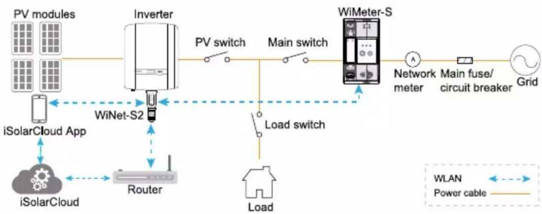
flowchart
graph LR
    A["PV modules"] --> B["Inverter"]
    C["iSolarCloud App"] --> D["WiNet-S2"]
    E["iSolarCloud"] --> F["Router"]
    G["WiMeter-S"] --> H["Network meter"]
    I["Load switch"] --> J["Load"]
    K["Main switch"] --> L["Main fuse/circuit breaker"]
    M["WLAN"] --> N["Power cable"]
    O["Grid"] --> P["Power cable"]
    Q["PV switch"] --> R["Main switch"]
    S["WiNet-S2"] --> T["Main switch"]
    U["Load switch"] --> V["Load"]
4 Delivery Contents
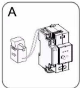
natural_image
Diagram of an electrical contactor device connected to a terminal block, labeled 'A' (no text or symbols on the device itself)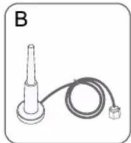
natural_image
Simple line drawing of a connector with a coiled cable and terminal block (no text or symbols)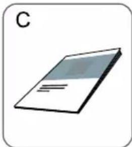
natural_image
Illustration of a closed book with visible pages and cover (no text or symbols)| No. | Description | Quantity |
| A | WiMeter-S | 1 |
| B | Antenna | 1 |
| C | Relevant documents, including the certificate of quality, warranty card, quick installation manual etc. | 1 |

NOTICE
- Contact SUNGROW or the distributor in case of any damaged or missing components.
Images in this manual are for reference only. The actual product received may differ.
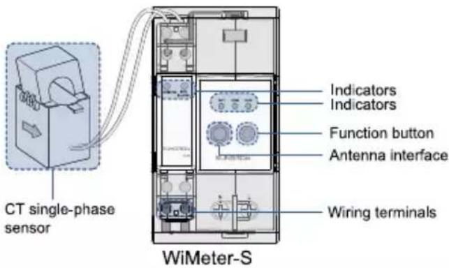
5 Appearance
5-1 Dimensions
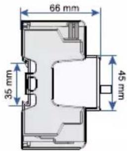
WiMeter-S
5-2 Indicator Status Description
| Device | Indicator | Color | Status | Description |
| WiMeter-S | RUN | Green | Off | Not connected to external power supply |
| Steady on | Connected to power supply | |||
| Blinking | Normal operation | |||
| Fast blinking | Manually finish device networking | |||
| COM | Red | Blinking | Normal internal communication | |
| Steady on | Abnormal internal communication | |||
| NET | Blue | Off | Not connected to WiNet-S2 or connection in process | |
| Steady on | Connected to WiNet-S2 | |||
| Blinking | Data communication in process | |||
| PWR/COM | Yellow | Steady on | Normal internal power supply | |
| Blinking | Internal communication in progress | |||
| Off | Abnormal internal power supply | |||
| 1000 imp/kWh | Red | Blinking | The active power is detected. | |
| Off | No active power is detected. |
Note: Blinking interval is 1s, and fast blinking interval is 200 ms.
5-3 Function Button Description
| Device | Function button | Description |
| WiMeter-S |  | Press and hold for 5~10 s to enter the network configuration mode |
5-4 Wiring Terminal
| Device | Mark | Description |
| WiMeter-S | L | Connected with line conductor |
| N | Connected with neutral conductor |
6 Installation

NOTICE
- Select a proper installation position considering the dimensions of the meter and the height of the antenna wiring terminal.
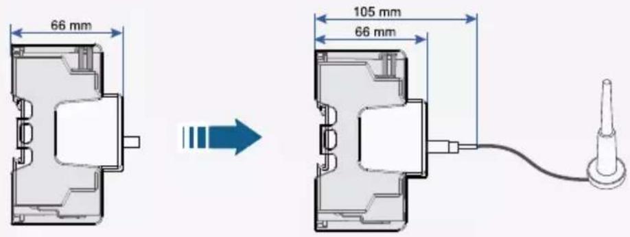
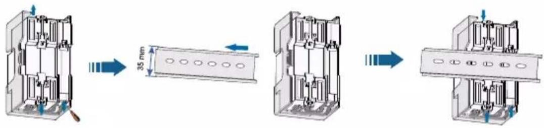
Step 1 Mount the WiMeter-S to a 35 mm DIN rail.
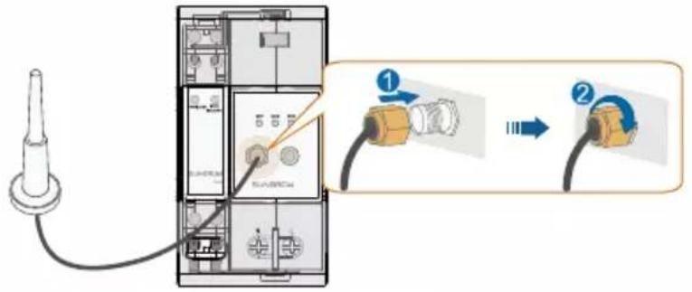
Step 2 Connect the antenna to the antenna interface on the WiMeter-S.
Step 3 Fix the antenna to an object outside the power distribution cabinet.
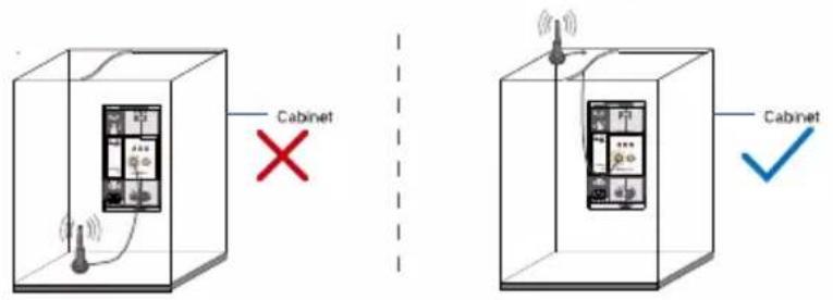

NOTICE
- It is recommended to place the antenna on the top of the cabinet.
7
Electrical Connection
Step 1 Disconnect the WiMeter-S from the voltage source and secure that it will not be connected.
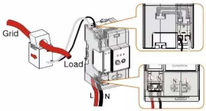
Step 2 Ensure that the conductors to be connected are free of voltage. Tighten the power wires to terminal L and terminal N. Place the CT single-phase sensor around the phase wire (L).

NOTICE
- Terminals at the bottom are used to connect the power supply. Pay attention to distinguishing between the L terminal and the N terminal, and connect the power cable correctly.
- Make sure that the CT single-phase sensor is installed in the right direction: the arrow on the sensor must point away from the grid towards the load.
Step 3 Cover the WiMeter-S with the insulating cover or contact protection of the power distribution cabinet. Connect the power distribution cabinet to the power supply.
8 Troubleshooting
| Device | No. | Fault name | Corrective measures |
| WiMeter-S | 1 | Meter offline | Check the COM indicator and the Net indicator of the WiMeter-S:If the COM indicator is always on, communication between the WiMeter-S and the meter is abnormal. Check the 485 connections inside the WiMeter-S.If the COM indicator blinks, communication between the WiMeter-S and the meter is normal. Further check the Net indicator.If the Net indicator is always off, the networking is abnormal. Refer to the corrective measures of abnormal networking.If the Net indicator is always on, wait for a few minutes to see if the meter can come back online. If so, there is no abnormality. If the meter goes repeatedly online and offline, the wireless communication quality is poor, causing serious packet loss. Please check whether the wiring of the WiMeter-S antenna is normal and whether it has been moved. |
| 2 | Abnormal networking | (1) Check whether the WiMeter-S is normally powered on.(2) Check whether the wiring of the WiMeter-S antenna is normal and whether it is moved.(3) Check the blue WLAN indicator on the WiNet-S2:If it blinks quickly, EasyConnect mode is enabled. Press the button 3 times quickly to exit the EasyConnect mode and check whether the networking is normal 2 mins later;(4) Check the blue Net indicator on the WiMeter-S:If it is always off, the WiMeter-S is not connected to any hot spot. Press the button for 5 - 10 s and check whether the networking is normal.If it is always on or blinks slowly, the WiMeter-S is connected to other device's hot spot rather than WiNet-S2's. Press the button for 5 - 10 s and check whether the networking is normal.(5) Check that the WiNet-S2 hot spot can be connected at the WiMeter installation location. Try to connect a computer or a mobile phone to the WiNet-S2's hot spot.If the connection fails, the WiNet-S2's hot spot has been connected by two other people. Disconnect other connections and check whether the networking is normal 2 mins later.If the hot spot of WiNet-S2 cannot be searched or the hot spot signal is weak, it is recommended to use WiFi Extender to boost the signal. Press the button for 5 - 10s and check whether the networking is normal. For more information on the use and installation of WiFi Extender, please contact SUNGROW Customer Service Centre. |
9 Commissioning
9-1 Networking Procedure
Step 1 Press and hold the function button on WiNet-S2 for 5 \~ 10 s, and release it after the RUN indicator turns to fast blinking in green. The WiNet-S2 is in networking mode.
Step 2 Press and hold the function button on WiMeter-S for 5 \~ 10 s, and release it after the RUN indicator turns to fast blinking in green. The WiMeter-S is in networking mode.

NOTICE
• Steps 1 and 2 are in no particular order, but make sure to finish the two steps within 2 minutes.
• After the WiMeter-S and WiNet-S2 are successfully networked, the NET indicator blinks blue, and the WiMeter immediately exits the networking mode.
Step 3 Check whether the WiMeter is online.
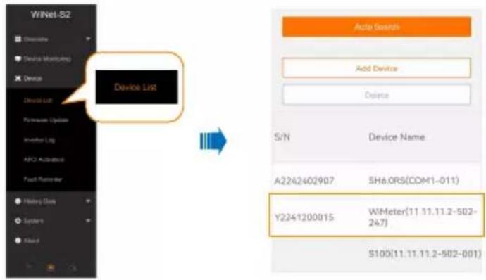
Method 1 Connect the cell phone to the hotspot of WiNet-S2, open a browser, and enter 11.11.11.1 in the address bar to enter the built-in web page. After logging in, check whether the S/N of the WiMeter displayed on the "Device List" page is the same as the S/N of the WiMeter that is manually networked. If it is the same, the WiMeter-S is successfully online.
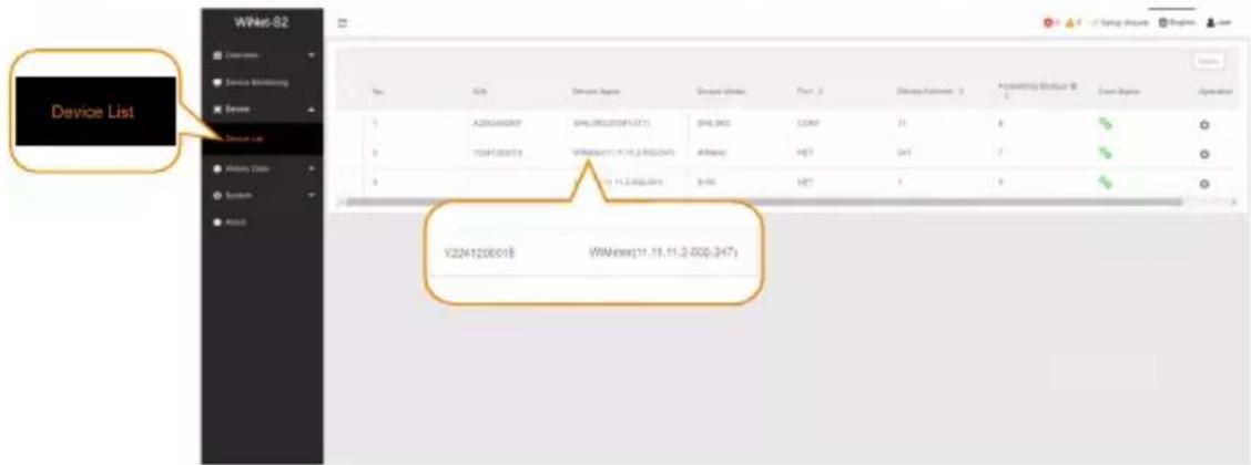
Method 2 Connect the WiNet-S2 to the PC by a network cable, open a browser, and enter 169.254.12.12 in the address bar to enter the built-in web page. After logging in, check whether the S/N of the WiMeter displayed on the "Device List" page is the same as the S/N of the WiMeter that is manually networked. If it is the same, the WiMeter-S is successfully online.
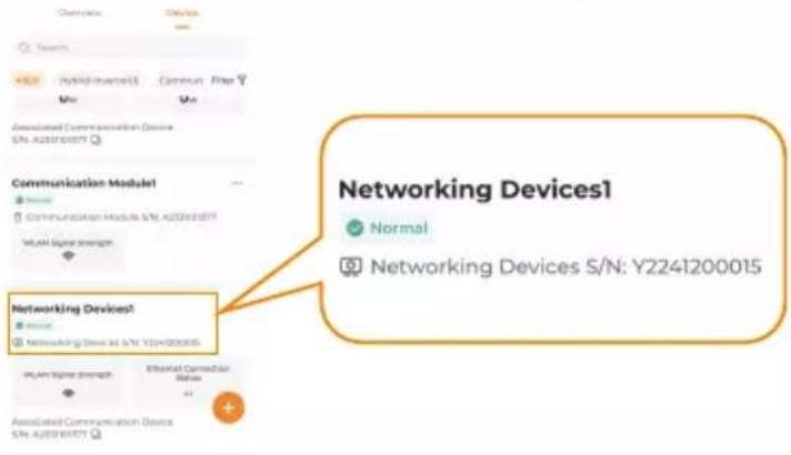
Method 3 Log in to iSolarCloud App, select the corresponding plant, and check whether the S/N of "Networking Devices" displayed on the "Device" page is consistent with the S/N of the WiMeter that is manually networked. If it is the same, the WiMeter-S is successfully online.
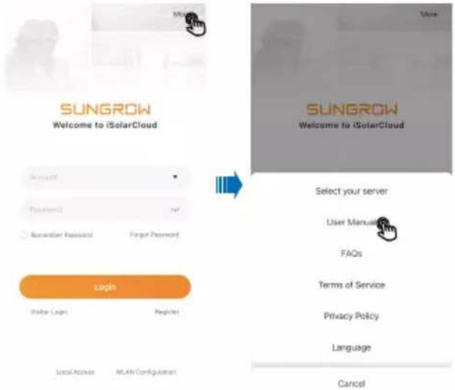
Prerequisite: The user has created a plant and added the device on iSolarCloud App. For specific operations, please refer to the iSolarCloud App User Manual.
Step 4 If the WiMeter goes online in step 3, the networking is successful. If the WiMeter does not come online within 5 minutes, repeat step 1 and 2.

NOTICE
- One WiMeter can only be networked with one WiNet-S2. If there are multiple WiNet-S2 on site, please carry out networking one by one following the above steps.
- If multiple inverters are connected in parallel on site, the WiNet-S2 mentioned in step 1 should be connected to the host inverter.
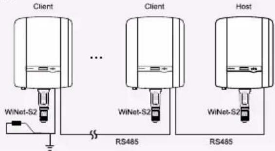
flowchart
graph TD
    A["Client"] --> B["WiNet-S2"]
    B --> C["..."]
    C --> D["RS485"]
    E["Client"] --> F["WiNet-S2"]
    F --> G["..."]
    G --> H["RS485"]
    I["Host"] --> J["WiNet-S2"]
    J --> K["..."]
    K --> L["RS485"]
- If the WiNet-S2 that the WiMeter-S has been successfully connected to is damaged, replaced, or has a networking error, repeat the above steps.
9-2 Viewing Information
Step 1 After powering on the WiMeter-S, observe the Net indicators on them, and enter the Web page of Winet-S2 when the Net indicators are steady on.
Login steps of WiNet-S2
Step 1 Connect your PC or iPad to the WLAN hotspot named "SG-WiNet-S2 communication module S/N".
Step 2 Open the browser (Chrome 60 or newer version is recommended) and enter 11.11.11.1 in the address bar to access the built-in Web. Click "Login" in the upper right corner of the interface, and enter the user name "admin" and the default password "pw8888".

NOTICE
• If the S/N is not the same, please carry out networking again referring to "9-1 Networking Procedure".
Step 3 If the device S/N is correct, view the information of the wireless meter on the page.
10 Technical Data
| Type Designation | WiMeter-S |
| Communication | |
| RS485 interface | 1 |
| LED indicator | 3 |
| WLAN | 802.11 b/gIEEE802.11n HT20@2.4GHzIEEE802.11n HT40@2.4GHz |
| Measurement Range | |
| Phase voltage range | 180 Vac ~ 288 Vac |
| Current | 0 ~100 A |
| Measurement Accuracy | |
| Voltage/Current/Power | ±0.5 % |
| Energy | ±1 % |
| Power Supply | |
| Power supply | 220 ~ 240 Vac |
| Max. Power consumption | 2.5 W |
| Ambient Conditions | |
| Operating ambient temperature range | -30°C~60°C |
| Allowable relative humidity range | ≤ 95 %(non-condensing) |
| Max. operating altitude | ≤ 4000 m |
| Degree of protection | IP20 |
| Mechanical Parameters | |
| Dimensions (W×H×D) | 59 X 109 X 66 mm |
| Weight | 350 g |
| Mounting type | DIN-Rail Mounting |

More information in the QR code or at http://support.sungrowpower.com
- Quick Installation Guide
- About This Guide
- NOTICE
- Safety Instructions
- DANGER
- WARNING
- Application Scenarios
- Delivery Contents
- Appearance
- 5-1 Dimensions
- 5-2 Indicator Status Description
- 5-3 Function Button Description
- 5-4 Wiring Terminal
- Installation
- 7
- Electrical Connection
- Troubleshooting
- Commissioning
- 9-1 Networking Procedure
- Step 3 Check whether the WiMeter is online.
- 9-2 Viewing Information
- Login steps of WiNet-S2
Marke : Sungrow
Modell : WiMeter-S
Kategorie : Nicht kategorisiert