
SG3.0RT - Nicht kategorisiert Sungrow - Kostenlose Bedienungsanleitung
Finden Sie kostenlos die Bedienungsanleitung des Geräts SG3.0RT Sungrow als PDF.


| Produkttyp | Netzgekoppelter Photovoltaik-Wechselrichter |
| Modell | SG3.0RT |
| Marke | Sungrow |
| AC-Ausgangsleistung (max.) | 3,0 kW |
| DC-Eingangsspannungsbereich | 80 V bis 550 V |
| MPP(T)-Spannungsbereich | 100 V bis 500 V |
| Maximaler DC-Eingangsstrom | 2 × 12 A |
| Maximaler Wirkungsgrad | > 97,5 % |
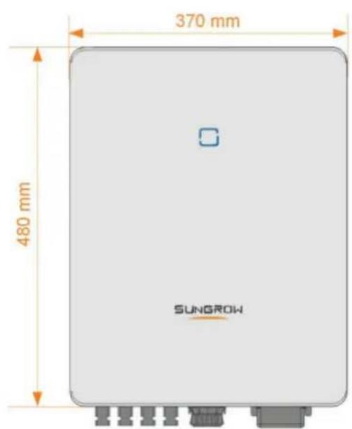
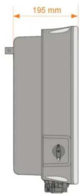
| Abmessungen (B × H × T) | 430 mm × 520 mm × 180 mm |
| Gewicht | 18 kg |
| Schutzklasse | IP65 |
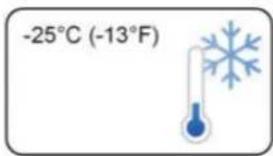
| Betriebstemperaturbereich | -25 °C bis +60 °C |
| Kühlung | Natürliche Konvektion (keine Lüfter) |
| Anzeige | OLED-Display und LED-Statusleuchten |
| Kommunikationsschnittstellen | RS485, Wi-Fi (optional), Ethernet (optional) |
| Überwachung | iSolarCloud-App oder Webportal |
| Zertifizierungen | VDE-AR-N 4105, IEC 62109, CE |
| Garantie | 5 Jahre (erweiterbar auf 10 oder 20 Jahre) |
| Reinigung | Gehäuse mit trockenem Tuch abwischen; Kühlrippen regelmäßig auf Staub prüfen |
| Sicherheitsfunktionen | Überspannungsschutz (DC/AC), Erdschlussüberwachung, Inselbildungsschutz |
| Reparatur und Ersatzteile | Nur durch autorisierte Fachkräfte; Ersatzteile über Sungrow-Service |
| Entsorgung | Gemäß lokalen Elektronikschrottvorschriften |
Häufig gestellte Fragen - SG3.0RT Sungrow
Benutzerfragen zu SG3.0RT Sungrow
0 Frage zu diesem Gerät. Beantworten Sie die, die Sie kennen, oder stellen Sie Ihre eigene.
Eine neue Frage zu diesem Gerät stellen
Laden Sie die Anleitung für Ihr Nicht kategorisiert kostenlos im PDF-Format! Finden Sie Ihr Handbuch SG3.0RT - Sungrow und nehmen Sie Ihr elektronisches Gerät wieder in die Hand. Auf dieser Seite sind alle Dokumente veröffentlicht, die für die Verwendung Ihres Geräts notwendig sind. SG3.0RT von der Marke Sungrow.
BEDIENUNGSANLEITUNG SG3.0RT Sungrow
SG3.0RT / SG4.0RT / SG5.0RT / SG6.0RT /
SG7.0RT / SG8.0RT / SG10RT / SG12RT /
SG15RT / SG17RT / SG20RT
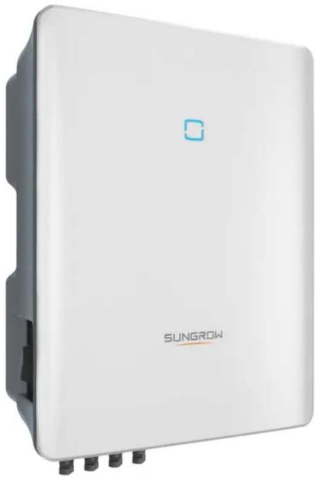
natural_image
White wireless device labeled 'SUNGROW' with a small blue logo on top, shown without any additional text or symbols.SUNGROW
! DANGER
WARNING
CAUTION
NOTICE
i
i
! DANGER
NOTICE
! DANGER
! WARNING
! WARNING
CAUTION
NOTICE
WARNING
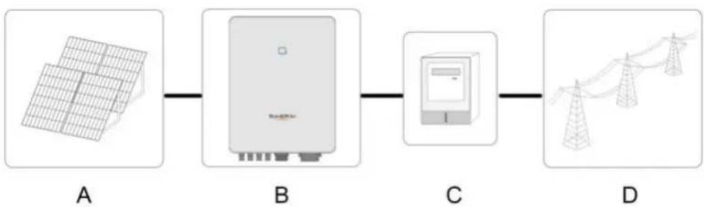
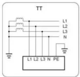
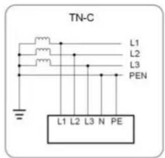
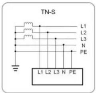
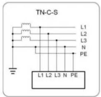
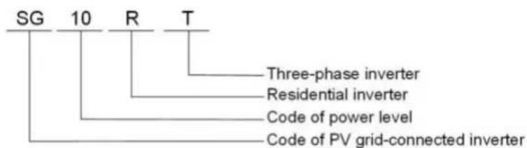
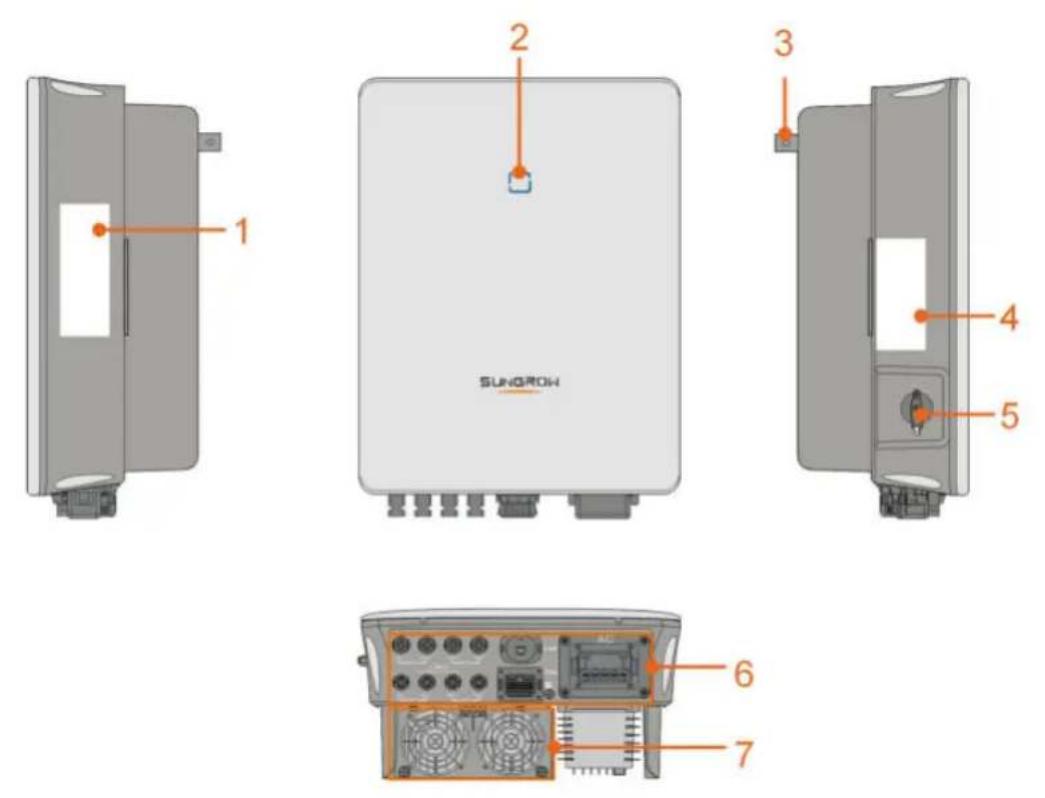





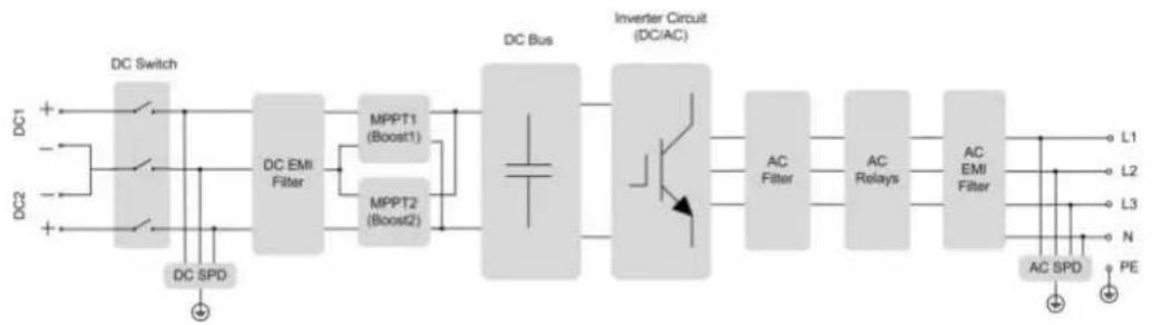
flowchart
graph LR
    DC1["DC Switch"] --> DCSPD["DC SPD"]
    DC2["DC Switch"] --> DCSPD
    DCSwitch --> DCEMIFilter["DC EMI Filter"]
    DCEMIFilter --> MPPT1["MPPT1 (Boost1)"]
    DCEMIFilter --> MPPT2["MPPT2 (Boost2)"]
    MPPT1 --> DCBus["DC Bus"]
    MPPT2 --> DCBus
    DCBus --> InverterCircuit["Inverter Circuit (DC/AC)"]
    InverterCircuit --> ACFilter["AC Filter"]
    InverterCircuit --> ACRelays["AC Relays"]
    ACFilter --> ACEMIFilter["AC EMI Filter"]
    ACRelays --> ACEMIFilter
    ACEMIFilter --> L1["L1"]
    ACEMIFilter --> L2["L2"]
    ACEMIFilter --> L3["L3"]
    ACEMIFilter --> N["N"]
    ACEMIFilter --> ACSPD["AC SPD"]
    ACEMIFilter --> PE["PE"]
i
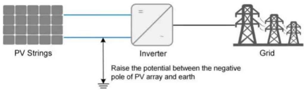
flowchart
graph LR
    A["PV Strings"] --> B["Inverter"]
    B --> C["Grid"]
    D["Raise the potential between the negative pole of PV array and earth"] --> B
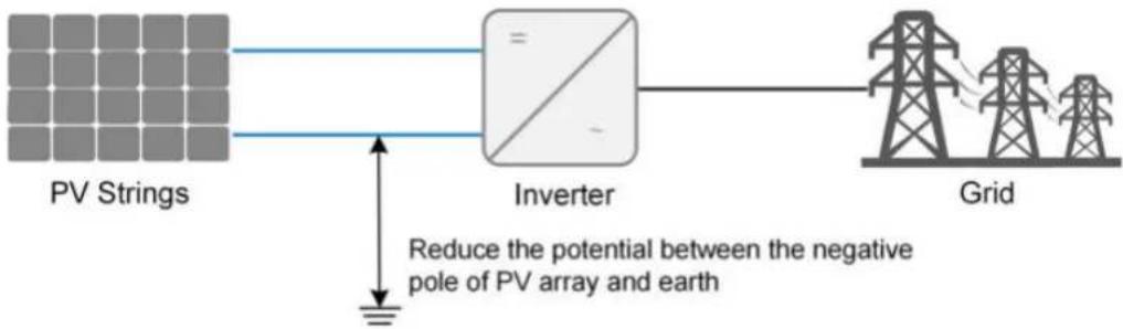
flowchart
graph LR
    A["PV Strings"] --> B["Inverter"]
    B --> C["Grid"]
    D["Reduce the potential between the negative pole of PV array and earth"] --> B
NOTICE
i
! DANGER
CAUTION
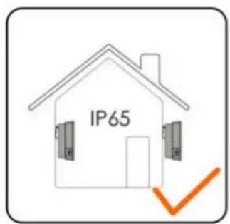
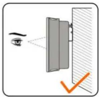
natural_image
Illustration of an eye projecting through a mirror onto a wall, with a checkmark indicating the optical path (no text or symbols present)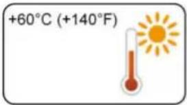
natural_image
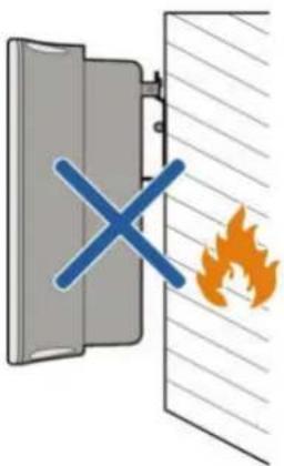
Diagram showing a fire incident with a blue 'X' symbol and an orange flame, no text or labels present.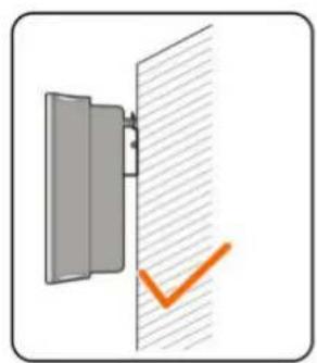
natural_image
Simple diagram showing a door with a checkmark and an orange checkmark on the wall (no text or symbols)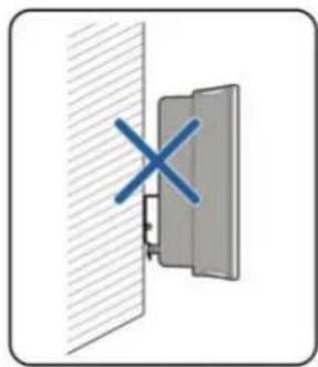
natural_image
Diagram showing a cross symbol on a wall-mounted device (no text or labels present)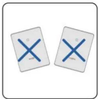
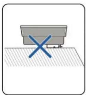
natural_image
Simple diagram showing a gray container with a blue 'X' mark on a textured surface (no text or symbols)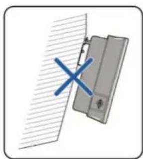
natural_image
Diagram showing a door with a blue X mark and diagonal hatching, no text or symbols present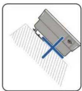
natural_image
Diagram of a mechanical component with a blue X-shaped tool inserted, no visible text or symbols
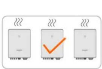
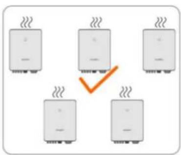
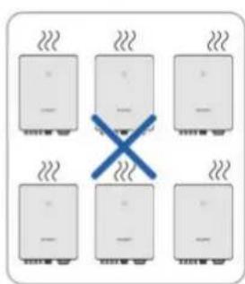

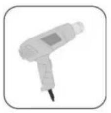
natural_image
White handheld medical or laboratory device with a needle inserted, shown in a rounded square frame (no text or symbols visible)
natural_image
Illustration of two crimping tools (no text or symbols visible)
natural_image
Illustration of two crimping tools (no text or symbols)
natural_image
Illustration of a screwdriver with a long handle and black end caps (no text or symbols)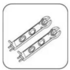
natural_image
Technical line drawing of two mechanical clamps or brackets with mounting holes (no text or symbols)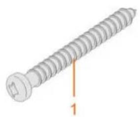
natural_image
Illustration of a screw with a labeled dimension line (no text or symbols on the screw itself)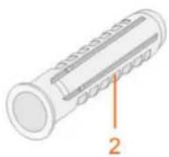
natural_image
Diagram of a cylindrical mechanical component with labeled parts (no text or symbols present)
NOTICE
! DANGER
WARNING
NOTICE
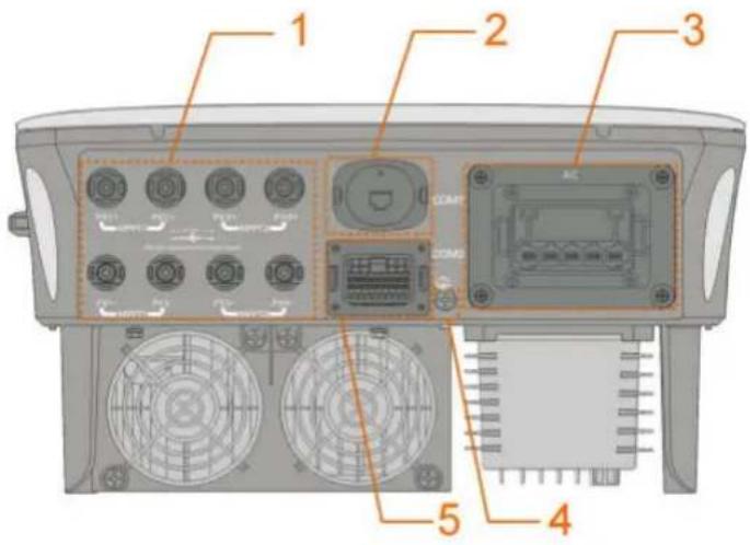

| RSD | NS | DRM | RS485-1 | DO | ||||
| RSD-1 | RSD-2 | NS-1 | NS-2 | D1/5 | D3/7 | R | A1 | NO |
| B3 | A3 | B2 | A2 | D2/6 | D4/8 | C | B1 | COM |
| RS485-3 | Meter | |||||||
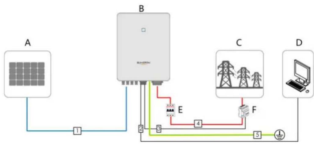
flowchart
graph TD
    A["Solar Panel A"] -->|1| B["Switch"]
    B -->|2| E["Power Supply E"]
    B -->|3| F["Power Supply F"]
    B -->|4| G["Power Supply G"]
    G -->|5| H["Laptop"]
    B -->|6| I["Ground"]
WARNING
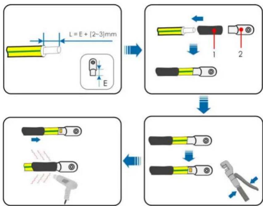
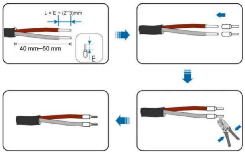
flowchart
graph TD
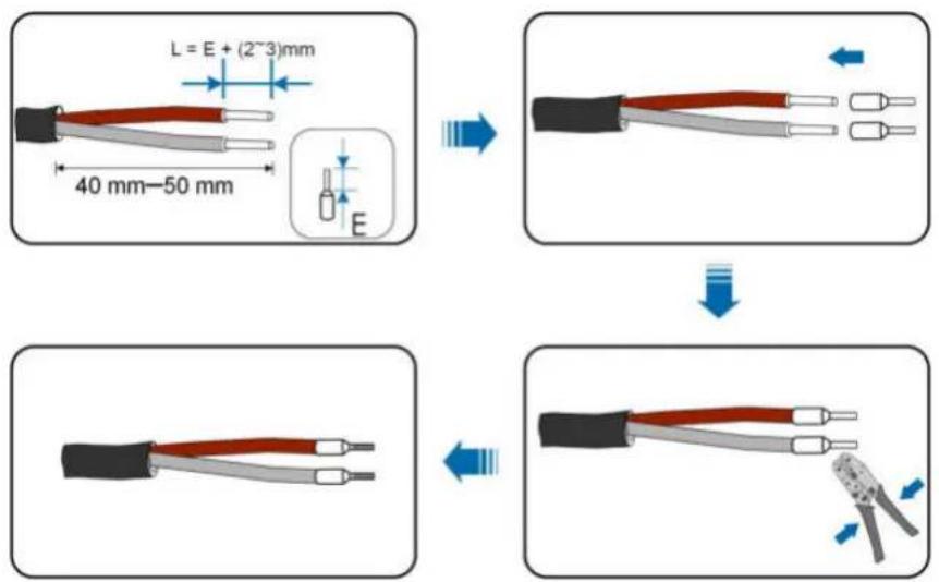
    A["Component 1: L = E + (2~3)mm"] --> B["Component 2: 1"]
    B --> C["Component 3: 2"]
    C --> D["Component 4: 1"]
    D --> E["Component 5: 2"]
    E --> F["Component 6: 1"]
    F --> G["Component 7: 2"]
    G --> H["Component 8: 1"]
    H --> I["Component 9: 2"]
    I --> J["Component 10: 1"]
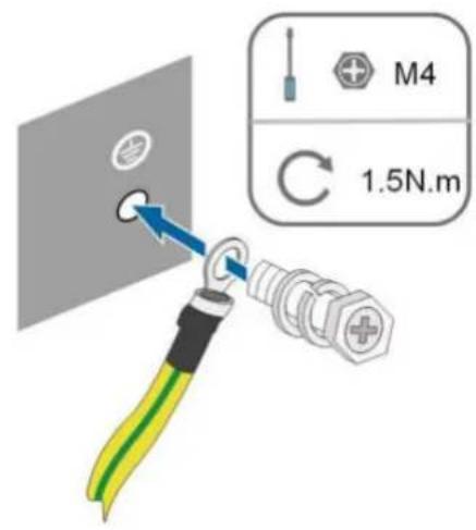
i
NOTICE
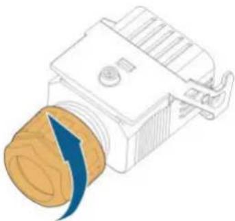
natural_image
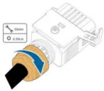
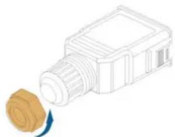
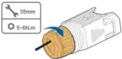
Illustration of a mechanical component with a blue arrow indicating rotation or force (no text or symbols)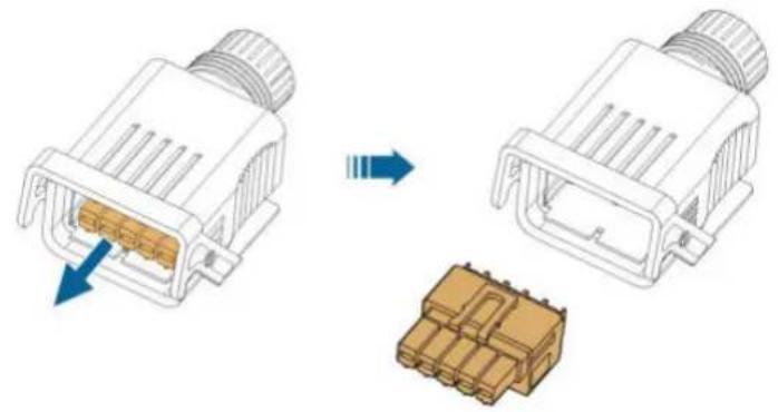
natural_image
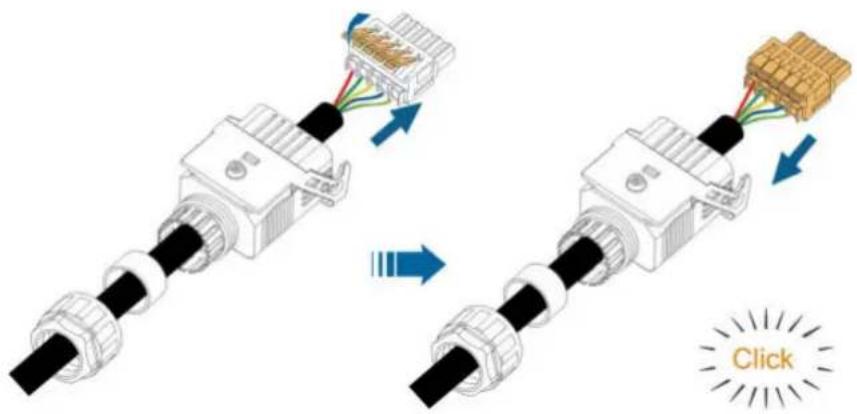
Diagram showing two connected electrical connectors with internal components, one being folded and the other assembled (no text or symbols present)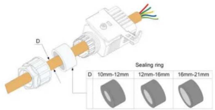
NOTICE

DANGER
natural_image
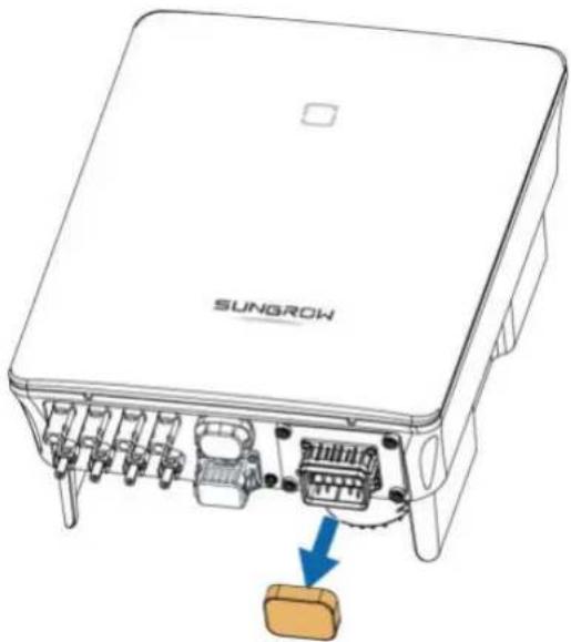
Diagram of a SunGROW device showing internal components and a highlighted component (no text or symbols present)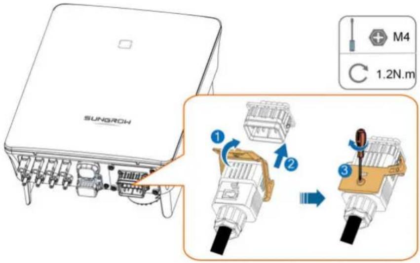
natural_image
Line drawing of a mechanical component emitting a rolled paper or cable (no text or symbols)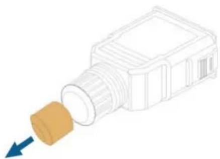
natural_image
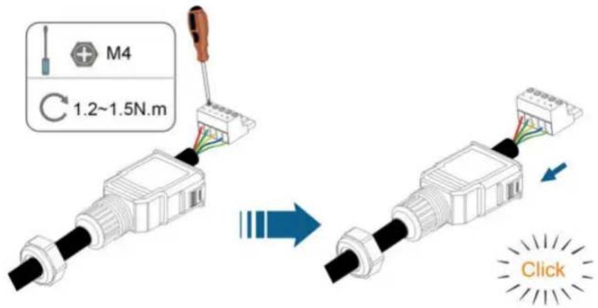
Diagram of a mechanical component with a blue arrow pointing to it, no text or symbols present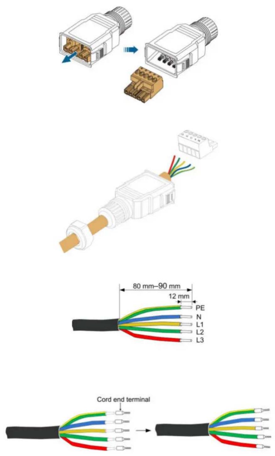
NOTICE
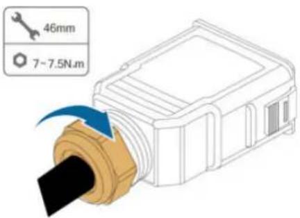
! DANGER
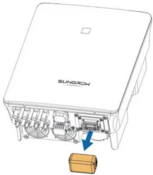
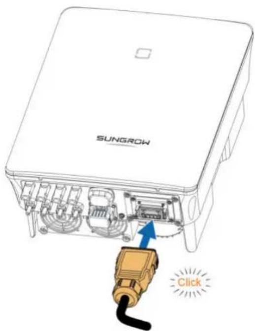
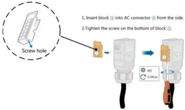
flowchart
graph TD
    A["Screw hole"] --> B["Insert block ① into AC connector ② from the side"]
    B --> C["Tighten the screw on the bottom of block ①"]
    C --> D["M3 0.5N.m"]
! DANGER
WARNING
NOTICE
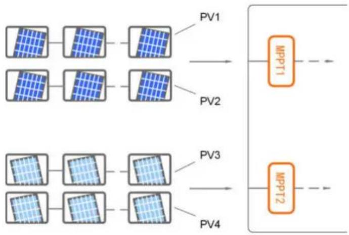
flowchart
graph LR
    A["Power Unit 1"] --> B["Power Unit 2"]
    C["Power Unit 3"] --> D["Power Unit 4"]
    E["Power Unit 5"] --> F["Power Unit 6"]
    G["Power Unit 7"] --> H["Power Unit 8"]
    I["Power Unit 9"] --> J["Power Unit 10"]
    K["Power Unit 11"] --> L["Power Unit 12"]
    M["Power Unit 13"] --> N["Power Unit 14"]
    O["Power Unit 15"] --> P["Power Unit 16"]
    Q["Power Unit 17"] --> R["Power Unit 18"]
    S["Power Unit 19"] --> T["Power Unit 20"]
    U["Power Unit 21"] --> V["Power Unit 22"]
    W["Power Unit 23"] --> X["Power Unit 24"]
    Y["Power Unit 25"] --> Z["Power Unit 26"]
    AA["Power Unit 27"] --> AB["Power Unit 28"]
    AC["Power Unit 29"] --> AD["Power Unit 30"]
    AE["Power Unit 31"] --> AF["Power Unit 32"]
    AG["Power Unit 33"] --> AH["Power Unit 34"]
    AI["Power Unit 35"] --> AJ["Power Unit 36"]
    AK["Power Unit 37"] --> AL["Power Unit 38"]
    AM["Power Unit 39"] --> AN["Power Unit 40"]
    AO["Power Unit 41"] --> AP["Power Unit 42"]
    AQ["Power Unit 43"] --> AR["Power Unit 44"]
    AS["Power Unit 45"] --> AT["Power Unit 46"]
    AU["Power Unit 47"] --> AV["Power Unit 48"]
    AW["Power Unit 49"] --> AX["Power Unit 50"]
    AY["MPPT1"] --> AZ["MPPT2"]
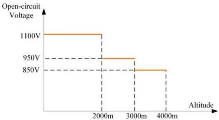
line
| Altitude | Open-circuit Voltage | | :--- | :--- | | 2000m | 1100V | | 3000m | 950V | | 4000m | 850V |! DANGER
CAUTION
i
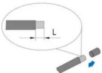
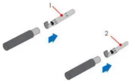
natural_image
Two mechanical tools with red arrows indicating movement or force, no text or symbols presentNOTICE
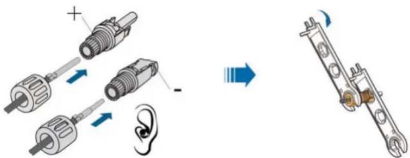
NOTICE
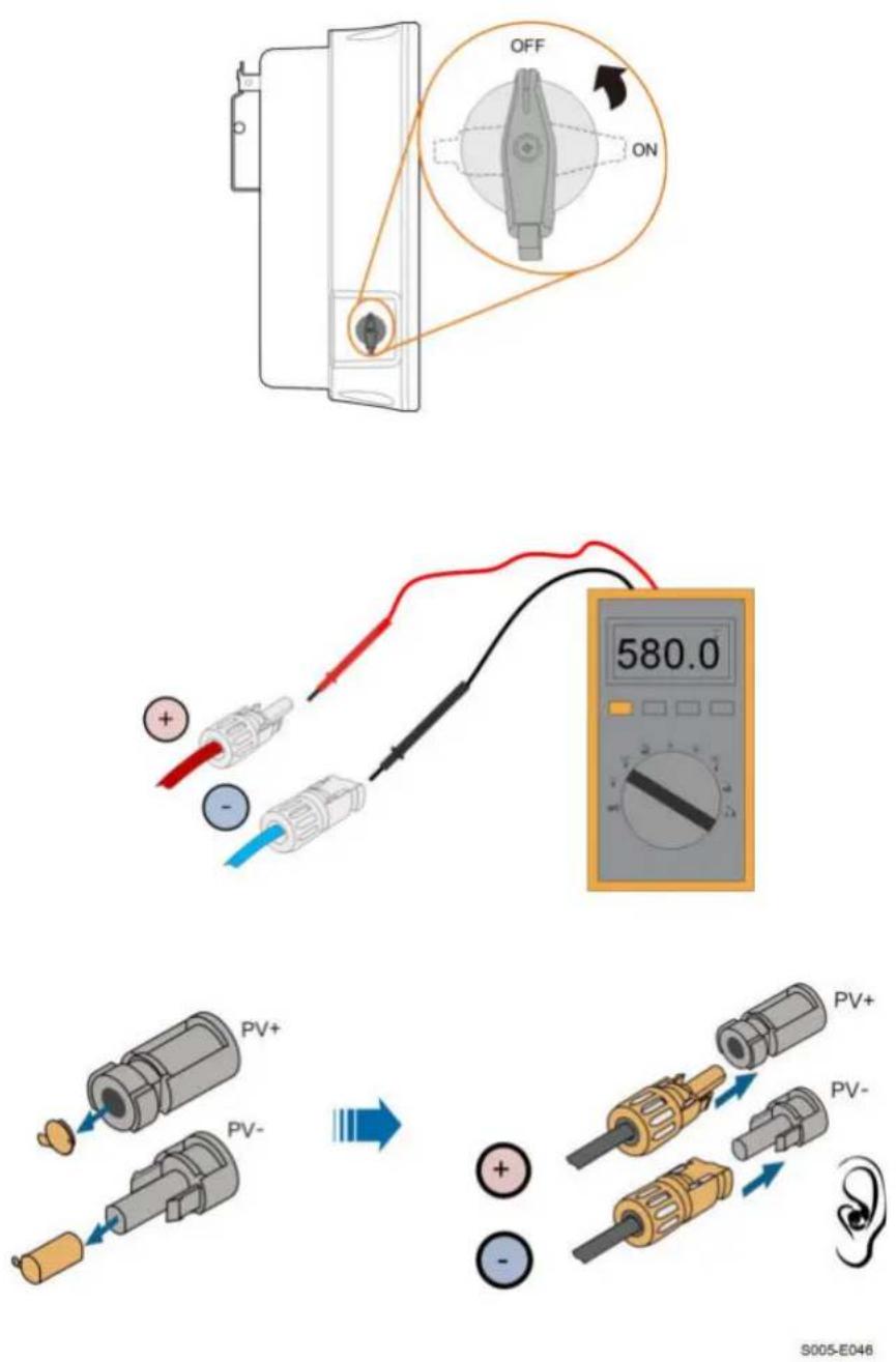
S005-E046
NOTICE

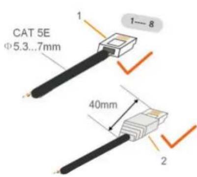
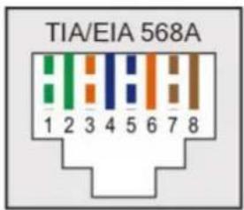
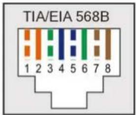
i
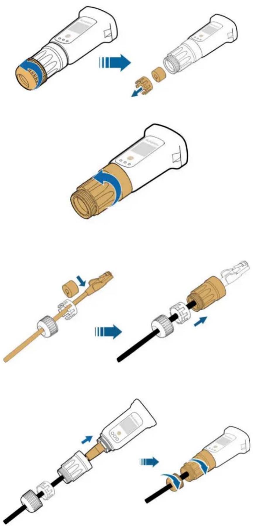
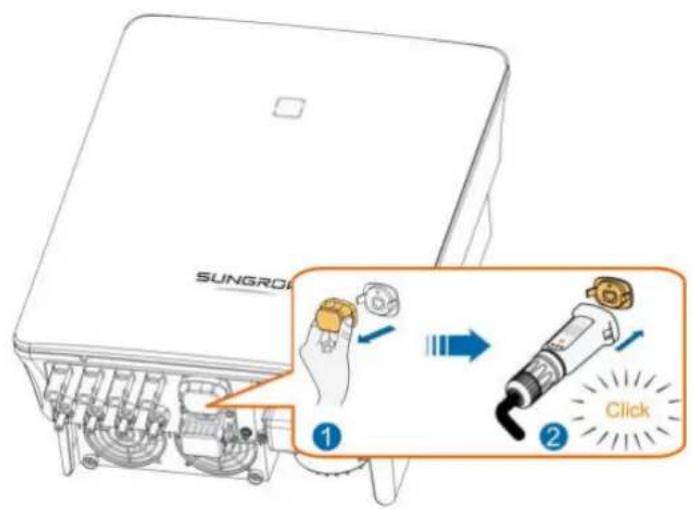
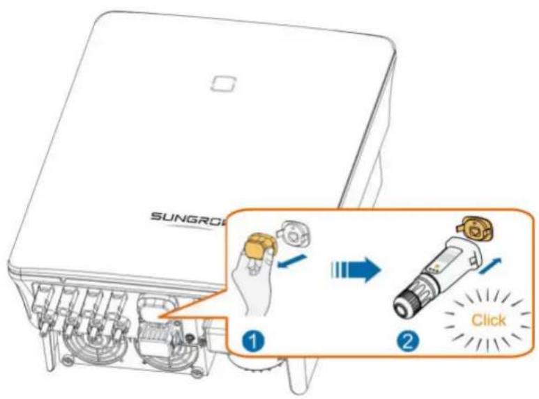
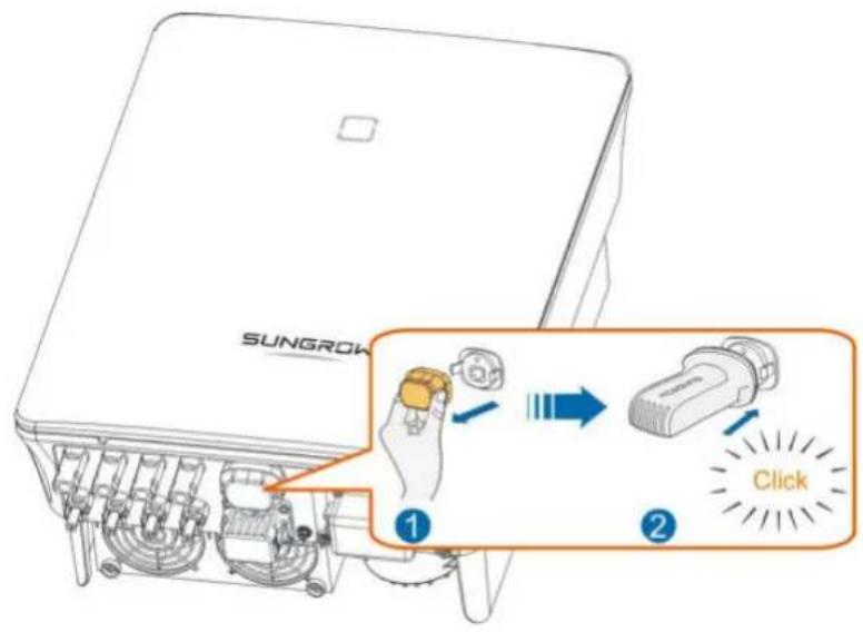
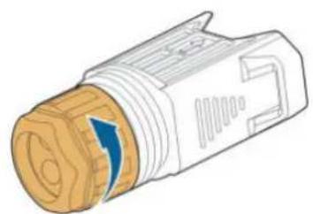
natural_image
Illustration of a mechanical connector with a blue arrow indicating direction (no text or symbols)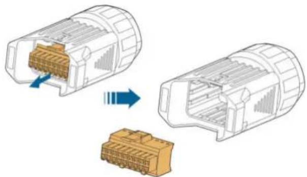
natural_image
Diagram showing two views of a connector with internal structure, one being open and the other closed, both without any text or symbols.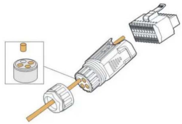
natural_image
Exploded view diagram of a mechanical connector assembly (no text or symbols)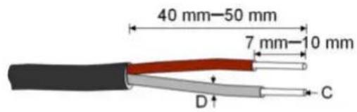
C = 0.5 ~mm^2 - 1.0 ~mm^2, D ≤slant 2.8 ~mm
natural_image
Diagram of a medical device with a connector and ear, showing internal components and a blue arrow indicating direction (no text or symbols)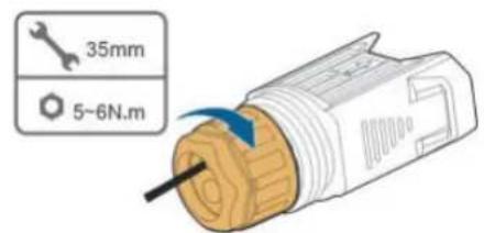
natural_image
Technical line drawing of a SunGROW electronic device with internal components and a connector (no text or symbols beyond branding)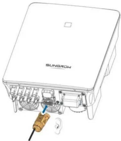
natural_image
Technical line drawing of a SunGROW device showing internal components and wiring (no text or symbols beyond branding)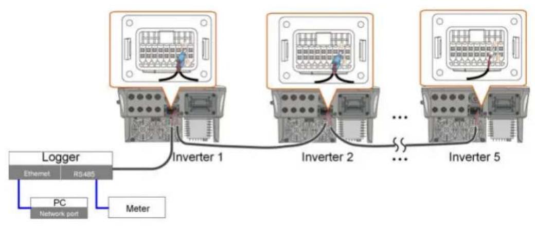
flowchart
graph TD
    A["Ethernet"] -->|Ethernet| B["Inverter 1"]
    C["PC Network port"] -->|Meter| B
    B --> D["Inverter 2"]
    D --> E["..."]
    E --> F["Inverter 5"]
    style A fill:#f9f,stroke:#333
    style C fill:#bbf,stroke:#333
    style D fill:#f9f,stroke:#333
    style E fill:#bbf,stroke:#333
    style F fill:#f9f,stroke:#333
i
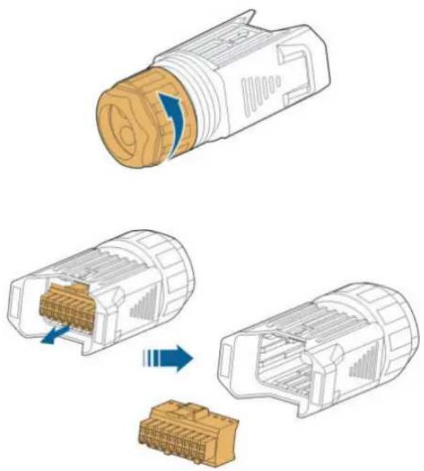
natural_image
Diagram showing three stages of a connector assembly: top view, internal socket, and bottom view with blue arrows indicating process flow (no text or symbols)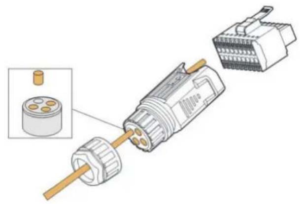
natural_image
Exploded view diagram of a mechanical connector assembly (no text or symbols)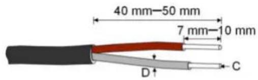
C = 0.5 ~mm^2 - 1.0 ~mm^2, D ≤slant 2.8 ~mm
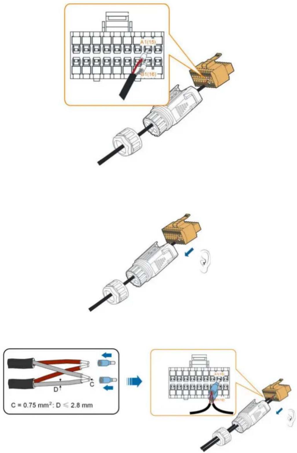
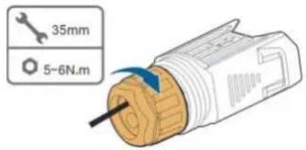
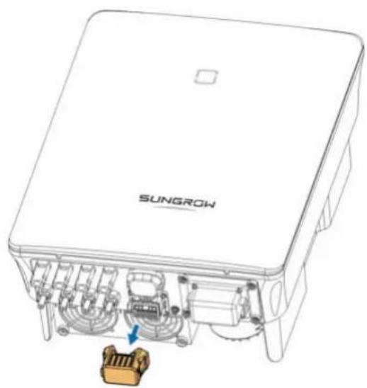
natural_image
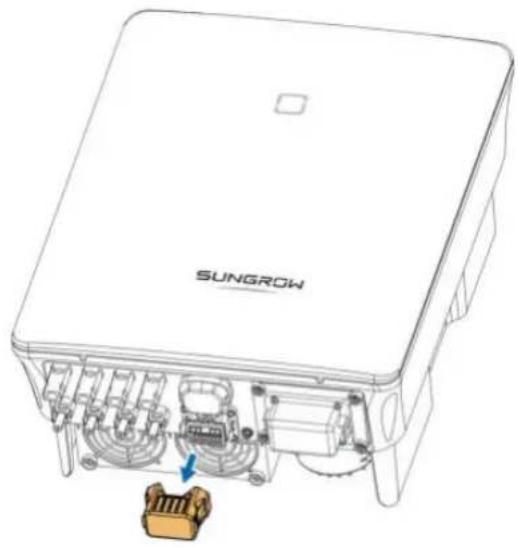
Technical line drawing of a SUNGROW electronic device with internal components and a highlighted connector (no text or symbols beyond branding)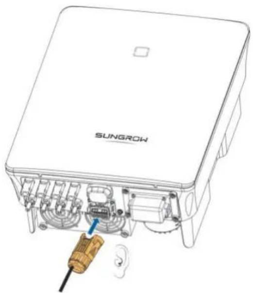
natural_image
Technical line drawing of a SUNGROW device with internal components and a screwdriver inserted (no text or symbols)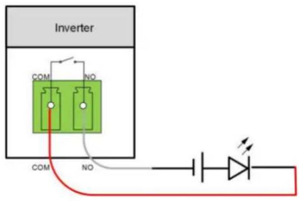
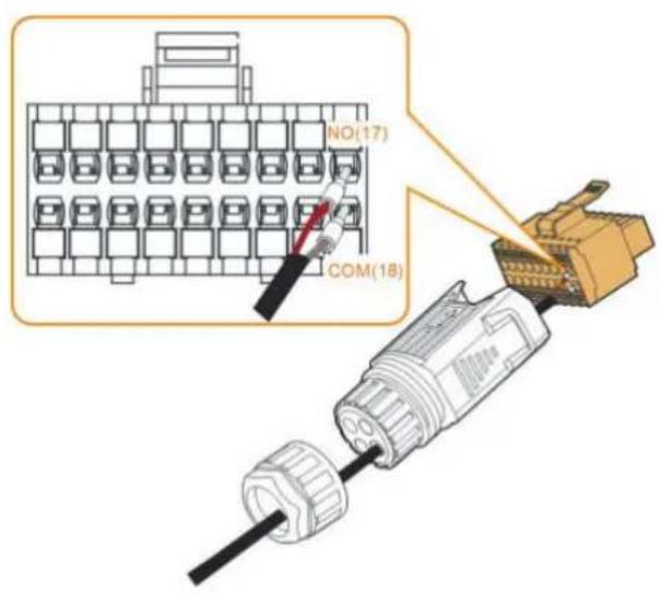
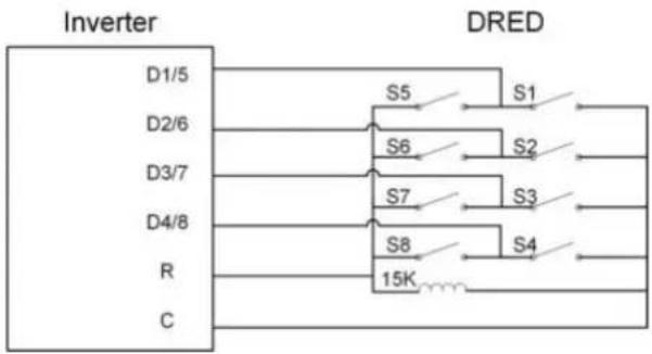
flowchart
graph TD
    A["Inverter"] --> B["DRED"]
    B --> C["D1/5"]
    B --> D["D2/6"]
    B --> E["D3/7"]
    B --> F["D4/8"]
    B --> G["R"]
    B --> H["C"]
    A --> I["S5"]
    A --> J["S6"]
    A --> K["S7"]
    A --> L["S8"]
    A --> M["15K"]
    B --> N["S1"]
    B --> O["S2"]
    B --> P["S3"]
    B --> Q["S4"]
    style A fill:#f9f,stroke:#333
    style B fill:#ccf,stroke:#333
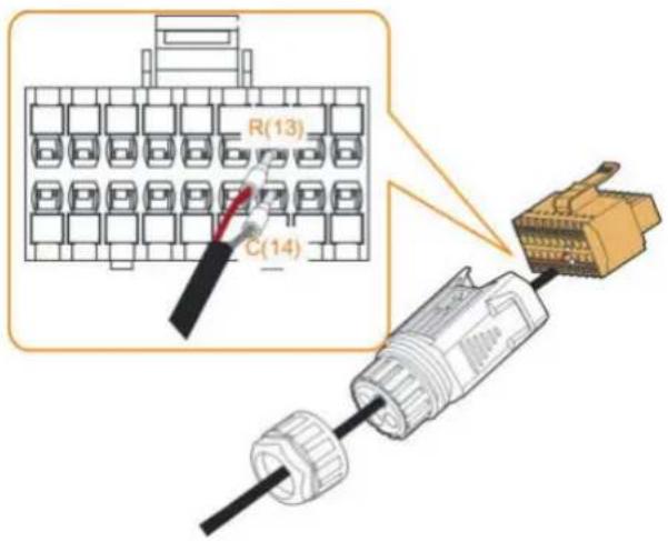
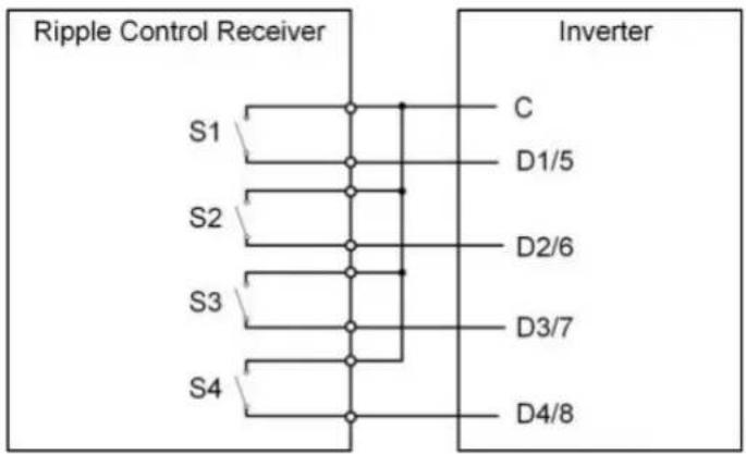
flowchart
graph TD
    subgraph Ripple_Control_Receiver
        S1 --> C
        S2 --> D1/5
        S3 --> D2/6
        S4 --> D3/7
        C --> Inverter
        D1/5 --> Inverter
        D2/6 --> Inverter
        D3/7 --> Inverter
        D4/8 --> Inverter
    end
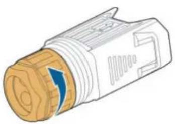
natural_image
Illustration of a mechanical connector with a blue arrow indicating direction (no text or symbols)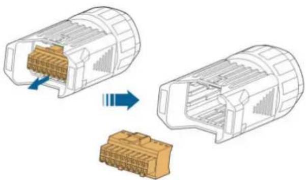
natural_image
Diagram showing two views of a connector housing with internal components, one being open and the other closed, both without any text or symbols.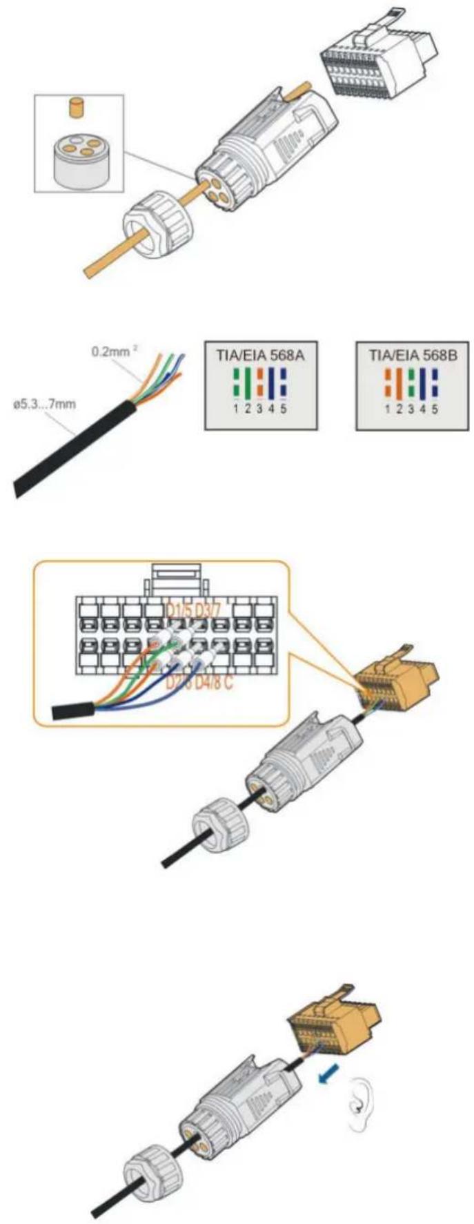

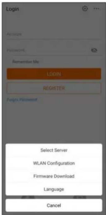


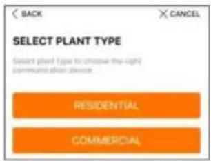
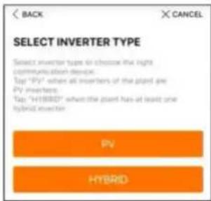
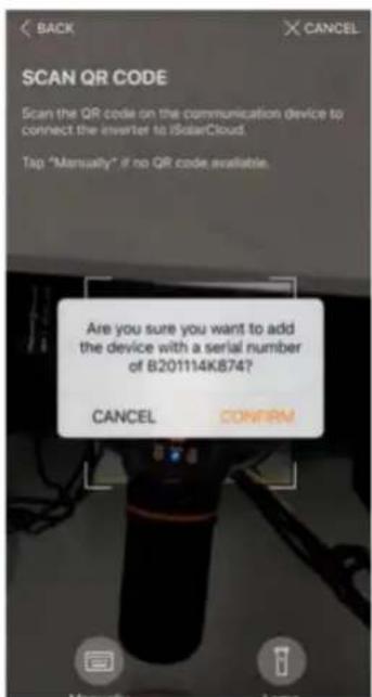

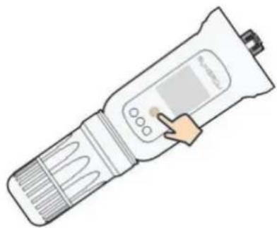
natural_image
Illustration of a handheld medical or laboratory device with a hand pointing to its screen (no text or symbols visible)NOTICE
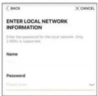
iSolarCloud provides important updates for your device.
Note: Make sure the DC side is powered on when updating.
CANCEL
UPDATE NOW

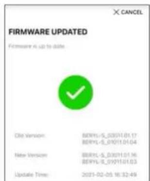
NOTICE
NOTICE
× CANCEL
ADD INVERTER
Tap "NEXT" to start configuration of the plant or tap "Acid Mace" to add more converters.

B201114K874

Add More
i
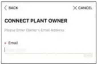
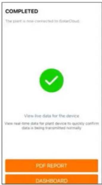
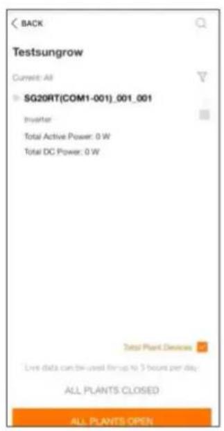
![BACK Testsungrow Current: All SG20RT[COM1-001]_001_001 Inverter Total Active Power: 0 W Total DC Power: 0 W Total Plant Devices CLOSE](/content/2026/05/833242/images/085f1e3b0480ca133410f348abf72326a1a4c84c19aa5d9c7b6502ac38d80599.jpg)
i
i


natural_image
Weather icon showing sun partially behind a cloud on orange background (no text or symbols)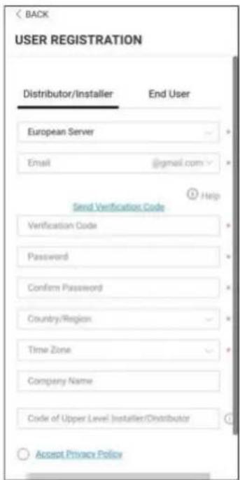
i
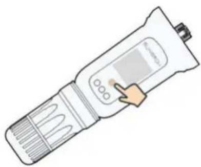
natural_image
Illustration of a handheld medical or laboratory device with a hand pointing to its screen (no text or symbols visible)i
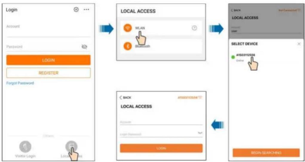
flowchart
graph TD
    A["Login Account"] --> B["LOCAL ACCESS WLAN Bluetooth"]
    B --> C["SELECT DEVICE A1503112556 Online"]
    C --> D["BEGIN SEARCHING"]

    subgraph Login
        A1["Password"]
        A2["LOGIN"]
        A3["REGISTER"]
        A4["Forgot Password"]
        A5["Visitor Login"]
        A6["Local Access"]
    end

    subgraph LOCAL ACCESS
        B1["WiLAN"]
        B2["Bluetooth"]
    end

    subgraph Select Device
        C1["A1503112556 Online"]
    end
NOTICE
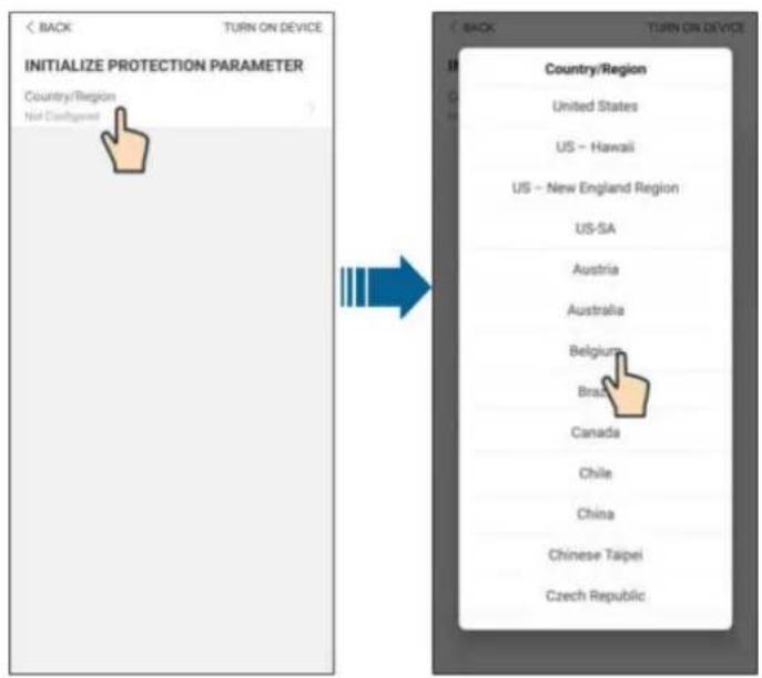
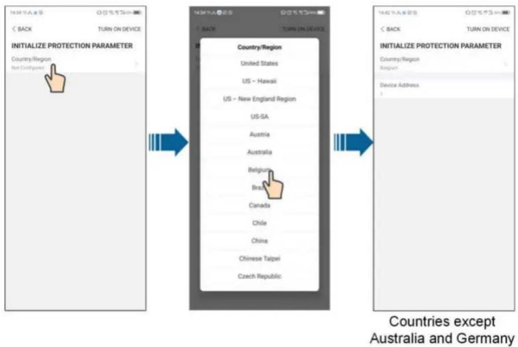
i
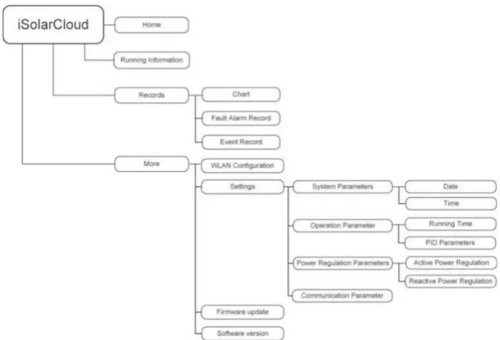
flowchart
graph TD
    A["iSolarCloud"] --> B["Home"]
    A --> C["Running Information"]
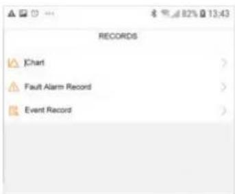
    A --> D["Records"]
    D --> E["Chart"]
    D --> F["Fault Alarm Record"]
    D --> G["Event Record"]
    A --> H["More"]
    H --> I["WLAN Configuration"]
    I --> J["Settings"]
    J --> K["System Parameters"]
    K --> L["Date"]
    K --> M["Time"]
    J --> N["Operation Parameter"]
    N --> O["Running Time"]
    N --> P["PID Parameters"]
    J --> Q["Power Regulation Parameters"]
    Q --> R["Active Power Regulation"]
    Q --> S["Reactive Power Regulation"]
    J --> T["Communication Parameter"]
    T --> U["Firmware update"]
    T --> V["Software version"]

line
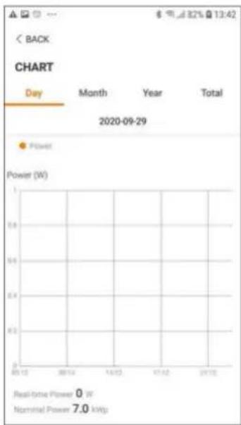
CHART | Day | Month | Year | Total | |---|---|---|---| | 2020-09-29 | Power | Power (W) | Power (W) | | 2013 | 0 | 0 | 0 | | 2014 | 0 | 0 | 0 | | 10/12 | 0 | 0 | 0 | | 11/12 | 0 | 0 | 0 | | 20/12 | 0 | 0 | 0 | Real-time Power: 0 W Nominal Power: 7.0 kW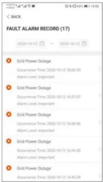
i

中国银行“A”字● 1800
< BACK
GRID POWER OUTAGE
Alarm Level: Important
Occurrence Time: 2020-10-12 18:06:39
Alarm ID: 10
Repair Advice
Generally, the device is reconnected to the grid after the grid recovers to normal. If the fault occurs repeatedly:
-
Check if the grid power supply is normal;
-
Check if AC calories are all firmly connected.
-
Check if all cables are connected to the correct terminals with or without live line and reverse
terminants (under or manual, live and reverse connections).
- If the fault still exists, Please contact customer service center of sungrow power.

i

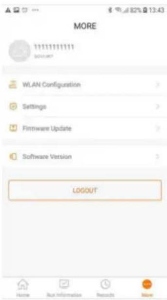
| BACK |
| SYSTEM PARAMETERS |
| Boot/Shutdown |
| Boot |
| Date Setting |
| 2020-09-23 |
| Time Setting |
| 13:43:18 |
| ARM Software Version |
| LCD_BERYL_S_V11_V01_A |
| MDSP Software Version |
| MDSP_BERYL_S_V11_V01_A |
| < BACK |
| RUNNING TIME |
| Connecting Time60 s |
| Reconnecting Time60 s |

Enable

Clear PID alarm

PID scheme

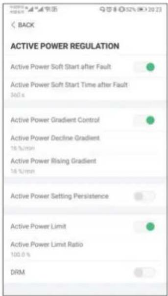
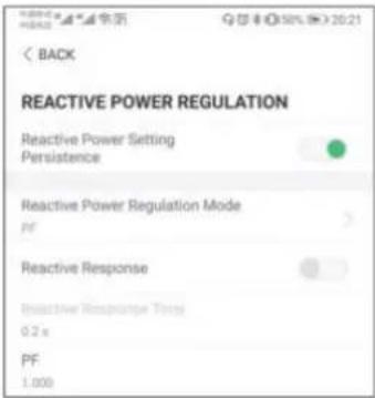
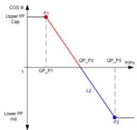
line
| Point | P/N | COS Φ | |---|---|---| | P1 | 1 | Upper PF Cap | | QP_P1 | 1 | 1 | | QP_P2 | 1 | 0 | | QP_P3 | 1 | 0 | | L2 | 1 | Lower PF Ind | | P2 | 1 | 0 |Curve A
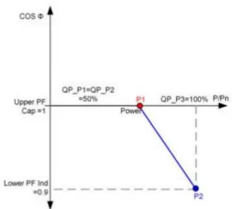
line
| Point | P/Pn (%) | COS Φ | |---|---|---| | Power | 50 | 1 | | P1 | 100 | 1 | | P2 | 100 | 0.9 | The chart includes a vertical dashed line at P/Pn = 0.9 and a horizontal line at COS Φ = 1. The legend indicates 'QP_P1=QP_P2' and 'Lower PF Ind', and 'Upper PF Cap' is marked as 1. The diagram shows a linear trend from P1 to P2, with a red dot marking the point (P1, 1).Curve B
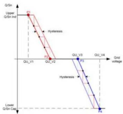
line
| Grid voltage | Q/Sn Ind | Hysteresis | | ------------ | -------- | ---------- | | QU_V1 | P1 | | | QU_V2 | P2 | | | QU_V3 | | P3 | | QU_V4 | | P4 |Curve A
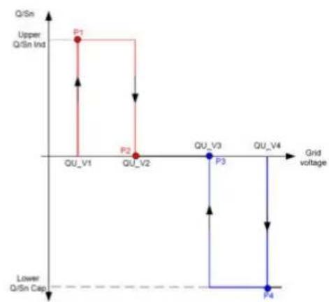
line
| Stage | Grid voltage | Q/Sn | | :--- | :--- | :--- | | Upper Q/Sn Ind | QU_V1 | 0 | | Upper Q/Sn Ind | QU_V2 | 0 | | Upper Q/Sn Ind | QU_V3 | 0 | | Upper Q/Sn Ind | QU_V4 | 0 | | Lower Q/Sn Cap | QU_V1 | 0 | | Lower Q/Sn Cap | QU_V2 | 0 | | Lower Q/Sn Cap | QU_V3 | 0 | | Lower Q/Sn Cap | QU_V4 | 0 |Curve B


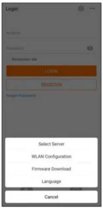
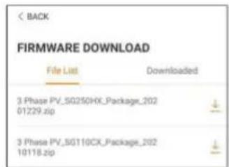
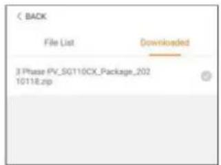
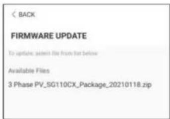
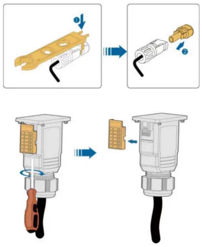
i

CAUTION
NOTICE
! DANGER
CAUTION
NOTICE
i
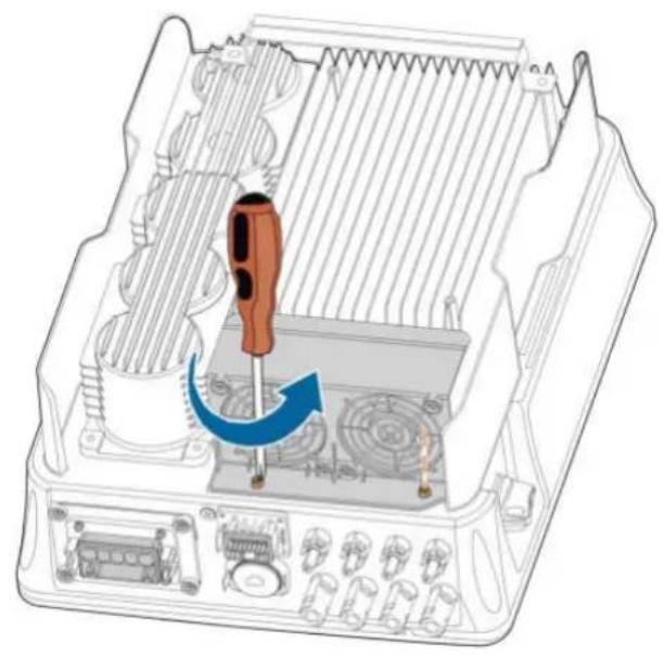
natural_image
Diagram of an internal electronic device showing a screwdriver inserted into a housing with cooling fins and ventilation slots (no text or symbols present)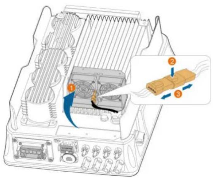
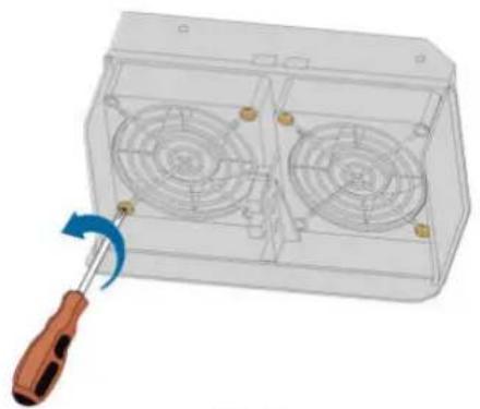
natural_image
3D rendering of a transparent enclosure with two fans and a screwdriver, showing internal components (no text or symbols)Back
natural_image
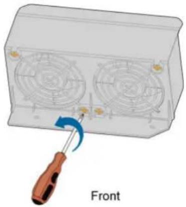
Diagram of a screwdriver inserted into a front-mounted fan device (no text or symbols on the device itself)Marke : Sungrow
Modell : SG3.0RT
Kategorie : Nicht kategorisiert