
APCRBC141 - Unterbrechungsfreie Stromversorgung APC - Kostenlose Bedienungsanleitung
Finden Sie kostenlos die Bedienungsanleitung des Geräts APCRBC141 APC als PDF.


| Produkttyp | Ersatzbatteriemodul für USV |
| Marke | APC |
| Modell | APCRBC141 |
| Gewicht | 11,7 kg |
| Kompatible USV-Modelle | APC Smart-UPS SRT2200XLx, SRT2200RMXLx |
| Kompatible externe Batteriepakete | APC SRT72BP, SRT72RMBP |
| Batterietyp | Blei-Säure, wartungsfrei |
| Ladezeit (90 % Kapazität) | Ca. 3 Stunden |
| Anzahl der Module pro Pack | 1 |
| Handhabung | Zum Einschieben den Griff verwenden; nicht zum Heben oder Tragen nutzen |
| Sicherheitshinweise | Schmuck entfernen; Batterien nicht öffnen, verbrennen oder beschädigen |
| Entsorgung | Batterien recyceln; Verpackungsmaterial wiederverwenden oder recyceln |
| Installation | Manuell in den dafür vorgesehenen Steckplatz einschieben |
| Rücksetzung des Installationsdatums | Über das Display: Config Menu > Battery > Installation Date eingeben |
| Zertifizierungen | Entspricht örtlichen und nationalen elektrischen Vorschriften |
Häufig gestellte Fragen - APCRBC141 APC
Benutzerfragen zu APCRBC141 APC
0 Frage zu diesem Gerät. Beantworten Sie die, die Sie kennen, oder stellen Sie Ihre eigene.
Eine neue Frage zu diesem Gerät stellen
Laden Sie die Anleitung für Ihr Unterbrechungsfreie Stromversorgung kostenlos im PDF-Format! Finden Sie Ihr Handbuch APCRBC141 - APC und nehmen Sie Ihr elektronisches Gerät wieder in die Hand. Auf dieser Seite sind alle Dokumente veröffentlicht, die für die Verwendung Ihres Geräts notwendig sind. APCRBC141 von der Marke APC.
BEDIENUNGSANLEITUNG APCRBC141 APC
Installation Guide Smart-UPS™ On-Line APCRBC152/APCRBC141
Safety Messages
Read the instructions carefully to become familiar with the equipment before trying to install, operate, service or maintain it. The following special messages may appear throughout this manual or on the equipment to warn of potential hazards or to call attention to information that clarifies or simplifies a procedure.
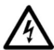
The addition of this symbol to a Danger or Warning safety label indicates that an electrical hazard exists which will result in personal injury if the instructions are not followed.

This is the safety alert symbol. It is used to alert you to potential personal injury hazards. Obey all safety messages that follow this symbol to avoid possible injury or death.

CAUTION
CAUTION indicates a potentially hazardous situation which, if not avoided, can result in minor or moderate injury.
CAUTION
CAUTION addresses practices not related to physical injury including certain environmental hazards, potential damage or loss of data.

Safety and General Information
Inspect the package contents upon receipt. Notify the carrier and dealer if there is any damage.
- Adhere to all local and national electrical codes.
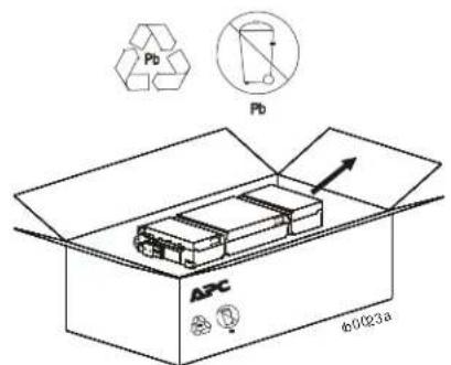
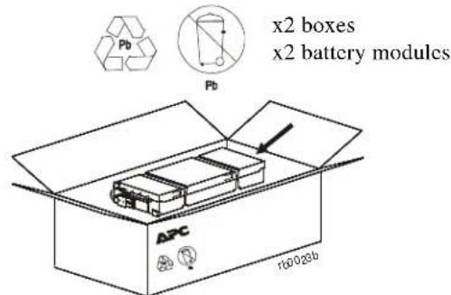
• Always recycle used batteries.
For information on recycling used battery modules, refer to the Battery Disposal Information sheet included with the replacement battery module.
• Recycle the package materials or save them for reuse.
Battery safety
- Before installing or replacing the batteries, remove jewelry such as wristwatches and rings. High short circuit current through conductive materials could cause severe burns.
- Do not dispose of batteries by burning them. The batteries may explode.
- Do not open or mutilate batteries. Released electrolyte is harmful to the skin and eyes, and may be toxic.
Replace Battery Modules
CAUTION
DAMAGE TO EQUIPMENT OR PERSONNEL
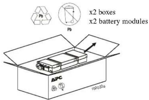
• The equipment is heavy. Each APCRBC152 battery module weighs 15.3 kg (33.7 lb) and each APCRBC141 battery module weighs 11.7 kg (25.8 lb).
• Always practice safe lifting techniques adequate for the weight of the equipment.
- Adhere to all local and national electrical codes.
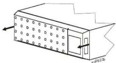
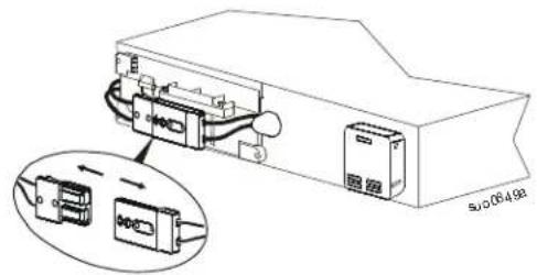
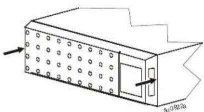
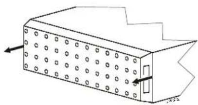
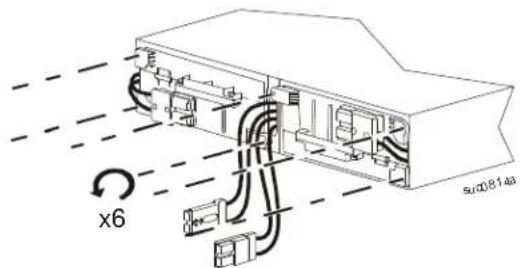
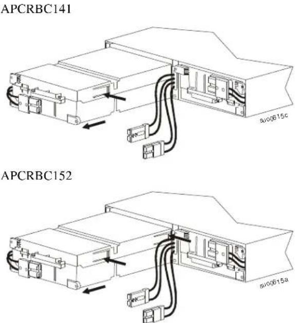
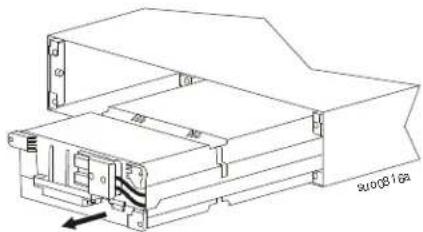
- Use the battery model handle to slide the battery modules in and out of the UPS and external battery pack (XLBP).
- Do not use the handle to lift or carry the battery module.
- When replacing the battery modules, replace with the same type of battery modules.
Failure to follow these instructions can result in equipment damage and minor or moderate injury.
Note: The batteries will charge to 90% capacity in the first three hours of operation on utility power. Do not expect full runtime capability during this initial charge period.
| Battery Module UPS XLBP | |
| APCRBC152 SRT3000XLx/SRT3000RMXLx SRT96BP/SRT96RMBP | |
| APCRBC141 SRT2200XLx/SRT2200RMXLx SRT72BP/SRT72RMBP | |
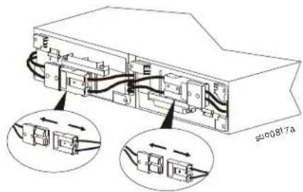
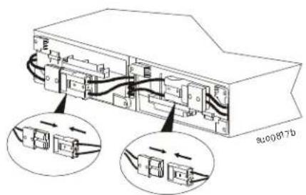
SRT2200XLx/SRT2200RMXLx/SRT3000XLx/SRT3000RMXLx UPS models
1
Z
natural_image
Technical line drawing of a rectangular device with circular holes and a door, showing directional arrows (no text or symbols)3
4
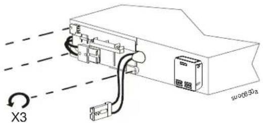
5
APCRBC141
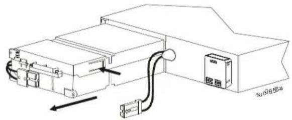
APCRBC152
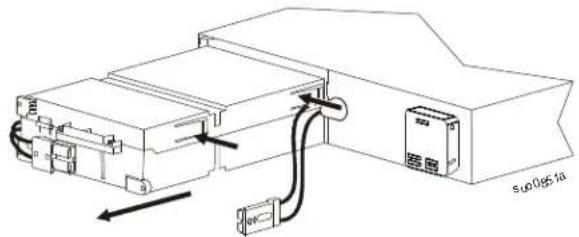
7
APCRBC141
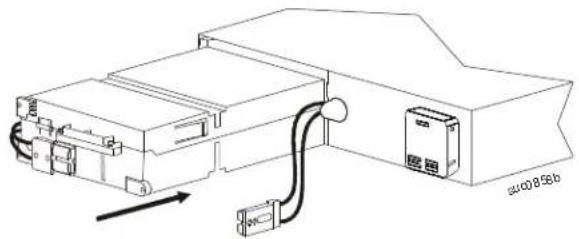
natural_image
Technical line drawing of an electrical enclosure with wiring and a door, no text or symbols presentAPCRBC152
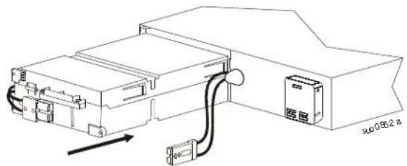
natural_image
Technical line drawing of an electronic device with cable and connector (no text or symbols)9
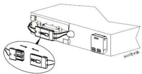
6
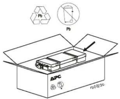
8
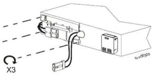
10
natural_image
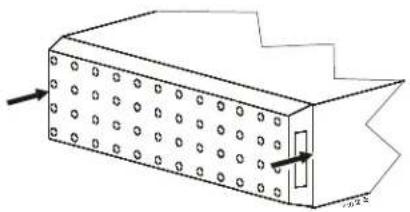
Technical line drawing of a rectangular device with circular holes and a door, showing internal structure and directional arrows (no text or symbols)SRT72BP/SRT72RMBP/SRT96BP/SRT96RMBP External battery packs
1
Z
natural_image
Isometric line drawing of a rectangular box with circular holes and an arrow indicating direction (no text or symbols)3
4
5
6
natural_image
Technical line drawing of a mechanical housing or enclosure component (no text or symbols visible)7
8
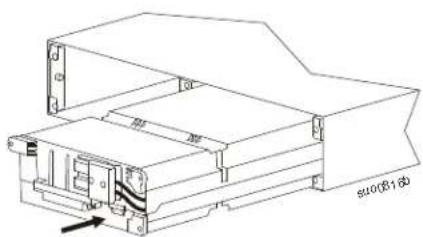
natural_image
Technical line drawing of a mechanical housing or enclosure with internal components and mounting brackets (no text or symbols)9
APCRBC141
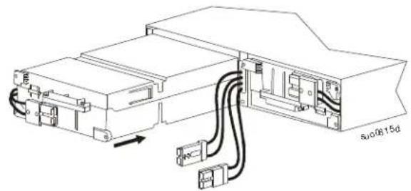
natural_image
Technical line drawing of an electronic device with connectors and wiring (no text or symbols)10
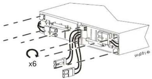
APCRBC152
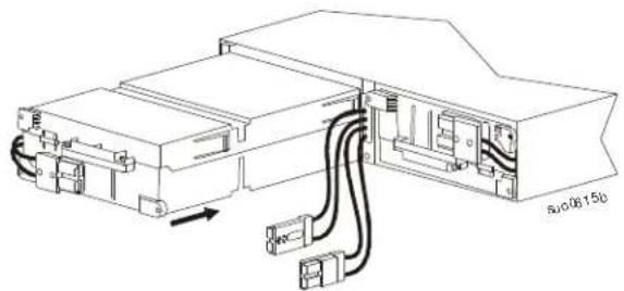
natural_image
Technical line drawing of an electronic device with cable and connector components (no text or symbols)11
12
natural_image
Diagram of a rectangular device with circular holes and an internal structure, showing directional arrows (no text or symbols)Reset Battery Installation Date
| 1 | POWER ON/OFF button | 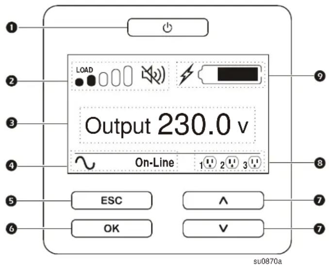 |
| 2 | Load iconDisable/mute audible alarm icon | |
| 3 | UPS status information | |
| 4 | Operation mode icons | |
| 5 | ESCAPE button | |
| 6 | OK button | |
| 7 | UP/DOWN arrow buttons | |
| 8 | Controllable outlet group status icons | |
| 9 | Battery status icons |
The battery installation date will appear on the display interface within two minutes of battery installation. If the installation date does not appear on the display interface, use the UP/DOWN arrow buttons to navigate to the Config Menu > Battery and enter the correct Installation Date.
When the replacement battery cartridge (RBC), is charged to full capacity, perform a Self Test and a Runtime Calibration Test.

- Installation Guide Smart-UPS™ On-Line APCRBC152/APCRBC141
- Safety Messages
- CAUTION
- Safety and General Information
- Battery safety
- Replace Battery Modules
- DAMAGE TO EQUIPMENT OR PERSONNEL
- SRT2200XLx/SRT2200RMXLx/SRT3000XLx/SRT3000RMXLx UPS models
- SRT72BP/SRT72RMBP/SRT96BP/SRT96RMBP External battery packs
- Reset Battery Installation Date
Marke : APC
Modell : APCRBC141
Kategorie : Unterbrechungsfreie Stromversorgung