
BE400-GR-OC - Wechselrichter APC - Kostenlose Bedienungsanleitung
Finden Sie kostenlos die Bedienungsanleitung des Geräts BE400-GR-OC APC als PDF.


| Produkttyp | USV (Wechselrichter) |
| Modell | BE400-GR-OC |
| Marke | APC |
| Eingangsspannung | 230 Vrms Nennspannung |
| Eingangsfrequenz | 50 - 60 Hz (automatische Erkennung) |
| Ausgangsspannung (Batteriebetrieb) | 230 Vac rms ±8% |
| USV-Kapazität (Batterie-Steckdosen) | 400VA / 240W |
| Anzahl Steckdosen gesamt | 8 (4 Batterie-Backup, 4 Überspannungsschutz) |
| Überspannungsschutz | 310 Joule, dauerhaft |
| Batterietyp | Versiegelte, wartungsfreie Blei-Säure-Batterie |
| Batterielebensdauer | 3 - 5 Jahre (abhängig von Zyklen und Umgebung) |
| Ladezeit | Mindestens 16 Stunden |
| Übertragungszeit | 6 ms typisch, maximal 10 ms |
| Abmessungen (H x B x T) | 285 x 230 x 86 mm |
| Gewicht | 5,4 kg |
| Betriebstemperatur | 0 °C bis 40 °C |
| Lagertemperatur | -15 °C bis 45 °C |
| Relative Luftfeuchtigkeit (Betrieb) | 0 bis 95 % (nicht kondensierend) |
| Betriebshöhe | 0 bis 3000 m |
| Sicherheitszulassungen | CE, Nemko-GS, PCBC, GOST, IEC62040-1-1, IEC60884, IEC61643-1 |
| EMV-Konformität | EN50091-2, EN55022 Klasse B |
| Garantie | 3 Jahre ab Kaufdatum |
Häufig gestellte Fragen - BE400-GR-OC APC
Benutzerfragen zu BE400-GR-OC APC
0 Frage zu diesem Gerät. Beantworten Sie die, die Sie kennen, oder stellen Sie Ihre eigene.
Eine neue Frage zu diesem Gerät stellen
Laden Sie die Anleitung für Ihr Wechselrichter kostenlos im PDF-Format! Finden Sie Ihr Handbuch BE400-GR-OC - APC und nehmen Sie Ihr elektronisches Gerät wieder in die Hand. Auf dieser Seite sind alle Dokumente veröffentlicht, die für die Verwendung Ihres Geräts notwendig sind. BE400-GR-OC von der Marke APC.
BEDIENUNGSANLEITUNG BE400-GR-OC APC
1 Connect Battery
For safety, the Back-UPS ES is shipped with one battery wire disconnected. The Back-UPS ES will not operate until the wire is connected to the touch safe battery terminal.
NOTE: Small sparks may occur during battery connection. This is normal.
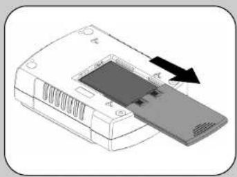
1 TURN the Back-UPS ES over and slide the battery compartment cover off of the battery housing.
2 LIFT the battery out of the compartment and connect the black wire to the negative (-) battery terminal. Ensure the batteries are installed as shown below.
3 Slide the battery compartment cover back onto the battery housing.
natural_image
Illustration of a device with a slide and arrow indicating direction (no text or symbols)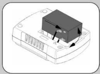
natural_image
Illustration of a device with a black component and directional arrows indicating motion (no text or symbols)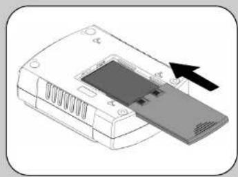
natural_image
Illustration of a printer with an arrow pointing to its cover (no text or symbols present)2 Connect Equipment
Battery Backup Surge Protection
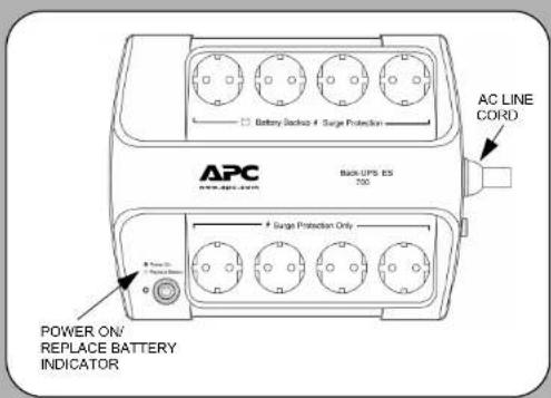
These outlets are powered whenever the Back-UPS ES is switched ON. During a power outage or other utility problems (brownouts, over-voltages), these outlets will be powered for a limited time by the Back-UPS ES. Plug your computer, monitor, and two other data-sensitive devices (external disk or tape drive) into these outlets.
Surge Protection Only
These outlets provide full-time protection from surges even if the Back-UPS ES is switched OFF. Plug your printer, fax machine, scanner, or other peripherals that do not need battery power into these outlets.
Place the Back-UPS ES to avoid:
- Direct sunlight
- Excessive heat
- Excessive humidity or contact with fluids

Plug the Back-UPS ES power cord directly into a wall outlet; not a surge protector or power strip. The wall outlet should be located near the equipment and be easily accessible.
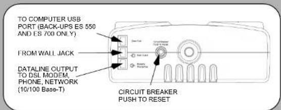
Connect Modem / Phone / DSL / Fax / 10/100 Base- T/HPNA to Surge Protection.
The Back-UPS protects a single line (2-wire) phone (including Digital Subscriber line - DSL), Home Phoneline Networking Association (HPNA) type equipment, modem, 10/100. Base-T Ethernet, or fax machines from surges when connected through the UPS as shown in the drawing below.
Note: Telephone Cable OR Network Cable should be connected to Surge Protection ports. Do not connect the UPS surge protection ports to both Telephone and Network System cables at the same time.
Connect Computer Cable (This is applicable for 550/700 only)
The supplied cable and software provide automatic file saving and shutdown of the operating system in the case of a sustained power outage. Connect the cable to the Data Port of the Back-UPS ES. Connect the other end of the cable to the USB port on your computer. The software will automatically find the USB Port of your computer.
3 Power On and Install Software
Press the ON/OFF switch to power the unit ON.
A single short beep and the green "Power On" indicator confirms that Back-UPS ES is on and ready to provide protection.
The Back-UPS ES should charge for at least 16 hours to ensure sufficient runtime. The unit is being charged whenever it is connected to utility power, whether the unit is turned ON or OFF.
Install the PowerChute Personal® Edition software (This is applicable for 550/700 only.)
Place the PowerChute Personal Edition CD-ROM into your computer and follow the installation instructions on the screen.
Status Indicators
The Back-UPS ES indicates operating status using a combination of visual and audible indicators. Use the following table to identify the status of the Back-UPS ES.
| Status Visual Indications | (Power On - Greon)(Replace Battery - Red) | Audible Indication A | Arm TerminatesWhen |
| Power On- UPS is supplying conditioned utility power to the load. | Power On LED - ON None | Not applicable. | |
| On Battery- UPS is supplying battery power to the load connected to the Battery outlets. | Power On LED - ON (off during beep) | Beeping 4 times every 30 seconds | UPS transfers back to Power On operation, or when UPS is turned off. |
| Low Battery Warning- UPS is supplying battery power to the load connected to the Battery outlets and the battery is near exhaustion. | Power On LED - flashing | Rapid beeping (every 1/2 second) | UPS transfers back to normal operation, or when UPS is turned off. |
| Replace Battery- Battery is in need of charging or is at the end of its usual life and must be replaced. | Power On and Replace Battery LEDs - Flashing (alternating) | Constant tone UPS turned off with the power switch. | |
| Battery Disconnected- The battery is disconnected or bad battery. | Replace Battery LED - flashing | Constant tone UPS turned off with the power switch. | |
| Overload Shutdown- During On Battery operation a battery power supplied outlet overload was detected. | None Constant tone UPS turned off with the | power switch. | |
| Sleep Mode- During On Battery operation the battery power has been completely exhausted and the UPS is waiting for utility power to return to normal. | None Beeping once every 4 seconds. | Utility power is restored, or if utility power is not restored within 32 seconds, or the UPS is turned off. | |
See the Troubleshooting section for additional assistance.
Troubleshooting
Use the table below to solve minor Back-UPS ES installation or operation problems. Consult APC Online Technical Support or call APC Technical Support for assistance with problems that cannot be resolved using the table below:
| Problem | Probable Cause | Solution |
| Back-UPS ES will not turn on. | Battery is disconnected or utility power is not available at the wall outlet. | Connect the battery (see Connect Battery) and ensure power is available at the wall outlet. |
| No power available at the Surge Protection Only outlets. | Surge Protection Only outlets have been overloaded. | Reduce the amount of equipment plugged into Surge Protection Only outlets. |
| Utility power not available at the wall outlet. | Ensure the fuse or circuit breaker for the outlet is not tripped, and that the wall switch controlling the outlet (if any) is in the ON position. | |
| Connected equipment loses power. | Equipment is connected to the Surge Protection Only outlets. | Ensure the equipment you want to stay powered during a power failure is plugged into the Battery Backup/Surge Protection outlets and NOT the Surge Protection Only outlets. |
| The Back-UPS ES is overloaded. | Make sure the equipment plugged into the Battery Backup/Surge Protection outlets of the unit are not overloading the capacity of the unit. Try removing some of the equipment and see if the problem continues. | |
| PowerChute Personal Edition software has performed a shutdown due to a power failure. | The Back-UPS ES is operating normally. | |
| The Back-UPS ES has exhausted its available battery power. | The Back-UPS ES can only operate on battery power for a limited amount of time. The unit will eventually turn off when the available battery power has been used. Allow the unit to recharge for 16 hours before continuing use of the unit. | |
| Connected equipment does not accept the stop-approximated sine waveform of the Back-UPS ES. | The output waveform is designed for computers and computer-related equipment. It is not designed for use with motor-type equipment. | |
| The Back-UPS ES may require service. | Contact APC Technical Support for further troubleshooting. | |
| The Power On indicator is lit and the Back-UPS ES is beeping four times every 30 seconds. | The Back-UPS ES is using battery. | The Back-UPS ES is operating normally and using battery power. Once On Battery, you should save your current work, power down your equipment, and turn the unit OFF. Once normal power is restored, you may turn the unit back ON and power your equipment. |
| The Power On indicator flashes once per second and the Back-UPS ES beeps once per second at the same time. | Battery capacity is low (about 2 minutes of use remaining). | The Back-UPS ES is about to shut off due to a low battery charge condition! When the unit boeps once every second, the battery has about 2 minutes of power remaining. Immediately power down your computer and turn the unit OFF. When normal power returns, the unit will recharge the battery. |
| Inadequate runtime. | The battery is not fully charged. | Allow the unit to charge by leaving it plugged into the wall for at least 16 hours. |
| Battery is near the end of useful life. | As a battery ages, the amount of runtime available will decrease. You can replace the battery by ordering one at www.apc.com. Batteries also age prematurely if the Back-UPS ES is placed near excessive heat. |
Specifications
| Item | Specification | BE400 | BE550 | BE700 |
| Input Voltage 230 Vrms Nominal | ||||
| Frequency 50 - 60 Hz (auto sensing) | ||||
| Brownout Transfer 180 Vrms, typical | ||||
| Over-voltage Transfer 266 Vrms, typical | ||||
| Output Voltage On Battery 230 Vac rms +/- 8% | ||||
| Total Amperage (8 outlets) 10 Amps (including UPS output) | ||||
| UPS Capacity (4 outlets) 400VA/240W | 550VA/330W | 700VA/405W | ||
| Frequency - On Battery 50/60 Hz +/-1 Hz | ||||
| Transfer Time | 6 ms typical, 10 ms maximum | |||
| Protection and Filter | AC Surge Protection | Full time, 310 joules | ||
| Phone/lax/DSL Surge Protection | Single line (2-wire) | |||
| Network Surge Protection | 10/100Base-T Ethernet | |||
| EMI/RFI Filter | Full time | |||
| AC Input | Rosettable circuit breaker | |||
| Battery | Type | Sealed, maintenance-free lead acid | ||
| Average Life | 3 - 5 years depending on the number of discharge cycles and environmental temperature | |||
| Physical | Not Weight | 5.4kg | 6.4kg | 6.8kg |
| Dimensions (H x W x D) | 285 x 230 x 86 mm(11.18" x 9.05" x 3.3 in.) | |||
| Operating Temperature | 0°C to 40 °C (32°F to 104°F) | |||
| Storage Temperature | -15°C to 45°C (5°F to 113°F) | |||
| Operating Relative Humidity | 0 to 95% non-condensing | |||
| Operating Elevation | 0 to 3000 m (0 to 10,000 ft) | |||
| Safety/Regulatory | Safely Approvals | CE, Nemko-GS, PCBC, GOST, IEC62040-1-1,IEC60884, IEC61643-1 | ||
| EMC Compliance | EN50091-2, EN55022 Class B | |||
Wall Mount of UPS
The UPS can be mounted vertically or horizontally to a wall surface. Use the template below to position the mounting fasteners (not supplied). Wall mount the UPS as follows:
- Hold this page against the wall in the desired mounting location.
- Use thumblacks or tape to hold this page in place against the wall. Use a sharp nail or pin to puncture the center of each template circle to mark the wall.
- Install the mounting fasteners at the marked locations. Leave the head of both fasteners 8 mm (5/16) out from the face of the wall. The fasteners must be able to support 6.8 Kg.
- Mount the UPS by positioning the key-hole slots over the mounting fasteners heads. For vertical mounting, slide the UPS down into place. For horizontal mounting, Turn it slightly counterclockwise until it is securely in place.
Order Replacement Battery
Replace with an APC qualified battery. Replacement batteries can be ordered from www.apc.com (valid credit card required). For Back-UPS ES 400, order APCRBC106 as directed by APC Technical Support. For Back-UPS ES 550, order RBC2. For Back-UPS ES 700, order RBC17.
Warranty
The standard warranty is 3 years from the date of purchase. APC's standard procedure is to replace the original unit with a factory reconditioned unit. Customers who must have the original unit back due to assigned asset tags and set depreciation schedules must declare such a need at first contact with APC Technical Support. APC will ship the replacement unit once the defective unit is received by the repair department or cross-ship upon the provision of a valid credit card number. The customer pays for shipping to APC, and APC pays ground freight transportation costs back to the customer.
Service
Please DO NOT RETURN Back-UPS ES to the place of purchase under any circumstances.
- Consult the Troubleshooting section to eliminate common problems.
- Verify the battery is connected (see Connect Battery) and that the Circuit Breaker is not tripped (see Troubleshooting section).
If you still have problems or questions, please contact APC via the Internet or at one of the phone numbers listed below. - Before contacting APC, please be sure to record the date purchased, UPS model, and serial number (on bottom of unit).
- Be prepared to troubleshoot the problem over the telephone with a Technical Support Representative. If this is not successful, the representative will issue a Return Material Authorization Number (RMA#) and a shipping address.
- Pack the unit in its original packaging. If the original packaging is not available, ask APC Technical Support about obtaining a new set. Pack the unit properly to avoid damage in transit. Never use foam beads for packaging. Damage sustained in transit is not covered under warranty (insuring the package for full value is recommended).
- Write the RMA# on the outside of the package.
- Return the unit by insured carrier to the address given to you by APC Technical Support.
APC Contact Information
| APC Europe | 353 91 702000 |
| APC Asia Pacific | 61 2 9955 9366 |
| Mexico | 292 0253 / 292 0255 |
| Brazil | 0800 555 272 |
| Worldwide | 1.401.789.5735 |
| Internet | http://www.apc.com |
| Technical Support | http://www.apc.com/support |
Marke : APC
Modell : BE400-GR-OC
Kategorie : Wechselrichter