
BVS240XDPDR - Wechselrichter APC - Kostenlose Bedienungsanleitung
Finden Sie kostenlos die Bedienungsanleitung des Geräts BVS240XDPDR APC als PDF.


| Produkttyp | Wechselrichter (DC-AC) |
| Modell | BVS240XDPDR |
| Marke | APC |
| Nennleistung | 2400 VA / 2400 W |
| Eingangsspannung (DC) | 48 V |
| Ausgangsspannung (AC) | 230 V ± 2 % |
| Ausgangsfrequenz | 50/60 Hz (automatische Erkennung) |
| Wellenform | Reine Sinuswelle |
| Wirkungsgrad | > 90 % bei Volllast |
| Abmessungen (B x H x T) | 438 x 86 x 400 mm (19 Zoll, 2 HE) |
| Gewicht | Ca. 12 kg |
| Schutzart | IP20 |
| Betriebstemperatur | 0 °C bis 40 °C |
| Lagertemperatur | -20 °C bis 60 °C |
| Luftfeuchtigkeit | 0 % bis 95 % (nicht kondensierend) |
| Anzeigen | LED-Statusanzeigen für Betrieb, Batterie, Alarm |
| Schnittstellen | USB, RS-232 (optional) |
| Schutzfunktionen | Überlast-, Kurzschluss-, Übertemperatur-, Tiefentladeschutz |
| Kühlung | Lüfter mit Temperaturregelung |
| Gehäusematerial | Metall (Stahlblech) |
| Einbauart | Rackmontage (19 Zoll) oder Standalone |
| Zubehör | Netzkabel, Bedienungsanleitung |
Häufig gestellte Fragen - BVS240XDPDR APC
Benutzerfragen zu BVS240XDPDR APC
0 Frage zu diesem Gerät. Beantworten Sie die, die Sie kennen, oder stellen Sie Ihre eigene.
Eine neue Frage zu diesem Gerät stellen
Laden Sie die Anleitung für Ihr Wechselrichter kostenlos im PDF-Format! Finden Sie Ihr Handbuch BVS240XDPDR - APC und nehmen Sie Ihr elektronisches Gerät wieder in die Hand. Auf dieser Seite sind alle Dokumente veröffentlicht, die für die Verwendung Ihres Geräts notwendig sind. BVS240XDPDR von der Marke APC.
BEDIENUNGSANLEITUNG BVS240XDPDR APC
Schneider Electric
User Manual Easy UPS DIN Rail Mount DC to DC Power Supply BVS240XDPDR/BVS480XDPDR
Safety and General Instructions
SAVE THESE INSTRUCTIONS - This manual contains important instructions that should be followed during installation and maintenance of the product.

Read the user documentation to become familiar with the equipment before trying to install or operate it.
- Switch off the input power before connecting or disconnecting the wires
- Use RED color wire for +ve and BLACK color wire for -ve connections
- Use insulated pin type lugs to be sure that the wire strands do not touch any metallic surface during connection/disconnection.
- Be sure that the wires do not touch any metallic surface during connection/disconnection.
- Be sure to connect the wires to the power supply unit first and then to battery pack(s).
- While disconnecting wires, be sure to disconnect the wires at battery pack(s) first and then at the power supply unit.
- Allow a minimum space of 50mm above the unit, 180mm below the unit and 10mm lateral distance from other devices to be sure of sufficient cooling.
- CAUTION: The enclosure can reach temperatures that exceed the burn thresholds for touchable surfaces, depending on the ambient temperature and load.
- Do not introduce any objects into the power supply unit.
Specifications
Environmental
| Ambient temperature | Operating -15 to +50 °C | |
| Storage -15 to +70 °C | ||
| Humidity 5 to 95% (Non condensing) | ||
| Altitude | Operating 3000 m (Max.) | |
| Storage 3000 m (Max.) | ||
| Audible Noise < 40 db | ||
| International Protection Code IP 20 | ||
| Operating Protection Class Class I | ||
Physical
| Dimensions without packaging (H x W x D) | 129 x 40 x 119 mm(5.08 x 1.57 x 4.69 in) |
| Dimensions with packaging (H x W x D) | 190 x 57x 188 mm(7.47 x 2.23 x 7.39 in) |
| Weight without packaging | 0.5 kg(1.1 lb) |
| Weight with packaging | 0.7 kg(1.54 lb) |
Input
| 240 W 480 W | ||
| Model BVS240XDPDR BVS480XDPDR | ||
| Nominal input voltage 24 VDC | ||
| Voltage Range | 21.6 – 28.6 VDC | |
| 240 W 480 W | ||
| Nominal Current | 10 A | 20 A |
| Runtime at full load (with 1 battery pack) | 10 min at 10 A load | 3 min at 20 A load |
| Efficiency at Nominal Voltage (Bypass mode, battery fully charged) | >95% | |
| Over current / Short circuit protection | 40 A Fuse | |
Output
| 240 W | 480 W | |
| Nominal output voltage U_N / tolerance | 24 VDC | |
| Switch On time (On delay time typical) | < 1 s | |
| Output current | 10 A | 20 A |
| Output over current limit | 10.5 A< OCP<13 A | 20.5 A<OCP<26 A |
| Short circuit protection | Yes | |
| Over temperature protection | Yes | |
| No. of units series connection | No | |
| No. of units parallel connection | No | |
Certification and Standards
IEC/EN/BS/UL 62368-1, CSA-C22.2 No. 62368-1, IEC/EN 60950-1, UL 508,
CSA C22.2 No. 14, IEC/EN 61010-1.
cTUVus CE, UKCA, GB 4943.1, CQC, EN 55032, EN55035, EN IEC 61000-6-2,
EN IEC 61000-6-4, EN IEC 61204-3, FCC 47 CFR Part 15, Subpart B & ICES-003 Issue 7
Front Panel Features
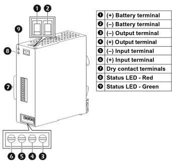
Installation
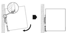
Mounting
NOTE: Be sure that the input/output terminal block is at the bottom while mounting the power supply unit on a 35 mm DIN rail.
- Locate the top hook of the rail mounting system (on the unit) with the unit slightly tilted upwards.
- Rotate the unit in clockwise direction till the latch of the rail mount system snaps on to the DIN rail and the unit cannot be rotated any further.
- Shake the unit slightly to be sure that it is securely mounted on the DIN rail.
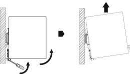
Dismounting
- Release the latch of the rail mount system (on the unit) by pulling it downwards using a screw driver.
- Tilt the unit upwards till the latch is free from the DIN rail.
- Slide the unit upwards till the top hook gets free from the DIN rail.
Dry contact details
All dry contacts (Pin3 to Pin10) are normally closed during operation and will open during an event.
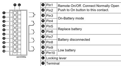
| Mode of Operation → Condition ↓ | Line Mode | Battery Mode | Battery Mode Low Battery | Line Mode Battery disconnected | Replace Battery |
| Remote On/Off | NA | NA | NA | NA | NA |
| On-Battery | NC | NO | NO | NC | NC |
| Replace Battery | NC | NC | NC | NC | NO |
| Battery Disconnected | NC | NC | NC | NO | NC |
| Low Battery | NC | NC | NO | NC | NC |
NOTE:
- NC = Normally Closed; NO = Normally Open; NA = Not Applicable.
- To insert wires into the Dry Contact terminals, press the locking lever (1) using a suitable screwdriver and insert the wire into the terminal (7). Remove the screwdriver to secure the wire to the terminal.
Connect Input, Output and Battery
CAUTION
RISK OF EQUIPMENT DAMAGE
- Wiring should be performed by a qualified electrician
- Wire size must comply with required current capacity as well as national and local electrical codes.
- Be sure to turn Off the input power supply before connecting or disconnecting input, output and battery wires to the terminals.
- Be sure that the wires do not touch each other or any metal object during
connection/disconnection. - Be sure to connect the battery wires first to the power supply unit and then to the battery.
- Be sure to disconnect wires first from the battery and then from the power supply unit.
- Be sure to crimp pin type lugs to the input, output and battery wires to prevent loose strands from touching any metal object.
Failure to follow these instructions can result in equipment damage and
minor or moderate injury.
Recommended wire sizes and tightening torque
| Wire Size | Torque | ||
| 240 W 480 W | |||
| Input/Output | 16 AWG (1.307 mm ^2 ) | 12 AWG (3.310 mm ^2 ) | 0 . 8 N m |
| Dry Contacts | 26 AWG (0.128 mm ^2 ) Not Applicable | ||
| Remote On/Off | |||
| Battery | 12 AWG (3.310 mm ^2 ) | 0.8 N m | |
NOTE:
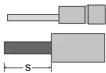
- Be sure to use a Pin Type cable lug for connecting the Input, Output and Battery wires
- To be sure of a secure connection, the wire insulation should be stripped (S) for approx. 6 mm, Be sure that all the strands are completely enclosed in the lug.
- Be sure that the positive and negative polarity wires are connected to the respective terminals on the power supply unit and the battery pack.
-
Connect the DC Input wires to the input terminals (refer "Front Panel Features" for details).
-
Connect the output wires to the output terminals (refer "Front Panel Features" for details).
-
Connect the battery wires to the battery terminals (refer "Front Panel Features" for details). NOTE:
- Be sure to connect the wires first to the terminals on the power supply unit and then to the terminals on the battery pack(s). - A maximum of 4 battery packs can be connected to a power supply unit.
Start up
NOTE: Be sure that the load is connected to the UPS before turning On the DC input.
Turn On the DC to DC Power Supply in On-Line mode
The power supply unit turns on automatically when the DC input is applied to the input terminals.
Turn On the DC to DC Power Supply in On-Battery mode
Press the REMOTE ON/OFF Push to On button, to turn on the power supply unit in On-Battery mode.
Turn off the DC to DC Power Supply
To turn Off, press the REMOTE ON/OFF push button.
Status Indicators
| Green LED Red LED UPS Status | ||
| Illuminated | Power supply unit is in on-line mode and the battery is charging/charged. | |
| Flashes 1 sec on and 1 sec off | Power supply unit is in on-battery mode. | |
| Green LED Red LED | UPS Status | |
| Flashes 0.3 sec on and 0.3 sec off | Low battery alert. | |
| Flashes 1 sec on and 1 sec off | An over current event has occurred. | |
| Illuminated | Power supply unit has tripped due to an over voltage event. | |
| Flashes An over temperature event has occurred. | ||
Limited Factory Warranty
Schneider Electric IT Corporation (SEIT), warrants its products to be free from defects in materials and workmanship for a period of TWO (2) years. The SEIT obligation under this warranty is limited to repairing or replacing, at its own sole option, any such defective products. Repair or replacement of a defective product or part thereof does not extend the original warranty period.
This warranty applies only to the original purchaser who must have properly registered the product within 10 days of purchase. Products may be registered online at warranty.apc.com.
SEIT shall not be liable under the warranty if its testing and examination disclose that the alleged defect in the product does not exist or was caused by end user or any third person misuse, negligence, improper installation, testing, operation or use of the product contrary to SEIT recommendations of specifications. Further, SEIT shall not be liable for defects resulting from: 1) unauthorized attempts to repair or modify the product, 2) incorrect or inadequate electrical voltage or connection, 3) inappropriate on site operation conditions, 4) Acts of God, 5) exposure to the elements, or 6) theft. In no event shall SEIT have any liability for damage, and 7) warranty for any product where the serial number has been altered, defaced, or removed.
EXCEPT AS SET FORTH ABOVE, THERE ARE NO WARRANTIES, EXPRESS OR IMPLIED, BY OPERATION OF LAW OR OTHERWISE, APPLICABLE TO PRODUCTS SOLD, SERVICED OR FURNISHED UNDER THIS AGREEMENT OR IN CONNECTION HEREWITH.
SEIT DISCLAIMS ALL IMPLIED WARRANTIES OF MERCHANTABILITY, SATISFACTION AND FITNESS FOR A PARTICULAR PURPOSE.
SEIT EXPRESS WARRANTIES WILL NOT BE ENLARGED, DIMINISHED, OR AFFECTED BY AND NO OBLIGATION OR LIABILITY WILL ARISE OUT OF, SEIT RENDERING OF TECHNICAL OR OTHER ADVICE OR SERVICE IN CONNECTION WITH THE PRODUCTS.
THE FOREGOING WARRANTIES AND REMEDIES ARE EXCLUSIVE AND IN LIEU OF ALL OTHER WARRANTIES AND REMEDIES. THE WARRANTIES SET FORTH ABOVE CONSTITUTE SEIT'S SOLE LIABILITY AND PURCHASER EXCLUSIVE REMEDY FOR ANY BREACH OF SUCH WARRANTIES. SEIT WARRANTIES EXTEND ONLY TO ORIGINAL PURCHASER AND ARE NOT EXTENDED TO ANY THIRD PARTIES. IN NO EVENT SHALL SEIT, ITS OFFICERS, DIRECTORS, AFFILIATES OR EMPLOYEES BE LIABLE FOR ANY FORM OF INDIRECT, SPECIAL, ESPECIAL OR ESPECIAL OR ESPECIAL OR ESPECIAL OR ESPECIAL USE, SERVICE OR INSTALLATION OF THE PRODUCTS, WHETHER SUCH DAMAGES ARE IN CONTRACT OR TORT, IRRESPECTIVE OF FAULT, NEGLIGENCE OR STRICT LIABILITY OR WHETHER SEIT HAS BEEN ADVISED IN ADVANCE OF THE POSSIBILITY OF SUCH DAMAGES. SPECIFICALLY, SEIT IS NOT LIABLE FOR ANY COSTS, SUCH AS LOST PROFITS OR REVENUE, WHETHER DIRECT OR INDIRECT, LOSS OF EQUIPMENT, LOSS OF USE OF EQUIPMENT, LOSS OF SOFTWARE, LOSS OF OTHER COSTS OF SUBSTITUANTS, CLAIMS BY THIRD PARTIES, OR OTHERWISE.
NOTHING IN THIS LIMITED WARRANTY SHALL SEEK TO EXCLUDE OR LIMIT OR DEATH OR PERSONAL INJURY RESULTING FROM ITS NEGLIGENCE OR ITS FRAUDULENT MISREPRESENTATION OF TO THE EXTENT THAT IT CANNOT BE EXCLUDED OR LIMITED BY APPLICABLE LAW.
To obtain service under warranty you must obtain a Returned Material Authorization (RMA) number from customer support. Customers with warranty claims issues may access the SEIT worldwide customer support network through the APC by Schneider Electric Web site: www.apc.com. Select your country from the country selection drop down menu. Open the Support tab at the top of the web page to obtain information for customer support in your region. Products must be returned with transportation charges prepaid and must be accompanied by a brief description of the problem encountered and proof of date and place of purchase.
Schneider Electric Worldwide Customer Support
Customer support for this or any other Schneider Electric product is available at no charge in any of the following ways:
- Visit the Schneider Electric Web site to access documents in the Schneider Electric Knowledge Base and to
– submit customer support requests.
- www.schneider-electric.com (Corporate Headquarters)
Connect to localized Schneider Electric Web sites for specific countries, each of which provides customer support information.
- www.schneider-electric.com/support/
Global support searching Schneider Electric Knowledge Base and using e-support.
Contact Schneider Electric IT (SEIT) Customer Support Center by telephone or
e-mail.
– Local, country specific centers: go to www.schneider-electric.com/support/contact for contact information.
For information on how to obtain local customer support, contact the Schneider Electric representative or other distributor from whom you purchased your Schneider Electric product.
Customer support and warranty information is available at www.se.com.
© 2022 Schneider Electric. All rights reserved. Schneider Electric,
the Schneider Electric logo, are trademarks of Schneider Electric SE, its subsidiaries or affiliated companies. All other brands may be trademarks of their respective owners.
990-6465B
03/2022

- Schneider Electric
- User Manual Easy UPS DIN Rail Mount DC to DC Power Supply BVS240XDPDR/BVS480XDPDR
- Safety and General Instructions
- Specifications
- Certification and Standards
- Installation
- Mounting
- Dismounting
- Dry contact details
- NOTE:
- Connect Input, Output and Battery
- CAUTION
- RISK OF EQUIPMENT DAMAGE
- Start up
- Turn On the DC to DC Power Supply in On-Line mode
- Turn On the DC to DC Power Supply in On-Battery mode
- Turn off the DC to DC Power Supply
- Limited Factory Warranty
- Schneider Electric Worldwide Customer Support
Marke : APC
Modell : BVS240XDPDR
Kategorie : Wechselrichter