TL-ANT2424B - TV-Antenne TP-LINK - Kostenlose Bedienungsanleitung
Finden Sie kostenlos die Bedienungsanleitung des Geräts TL-ANT2424B TP-LINK als PDF.

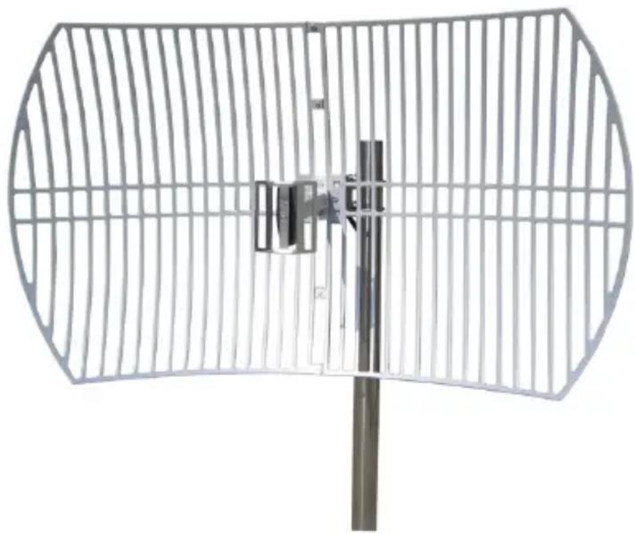
| Produkttyp | Gitter-Parabolantenne |
| Marke | TP-Link |
| Modell | TL-ANT2424B |
| Frequenzbereich | 2,4–2,5 GHz |
| Gewinn | 24 dBi |
| Impedanz | 50 Ω |
| VSWR | ≤ 1,5 |
| Horizontale Strahlbreite | 14° |
| Vertikale Strahlbreite | 10° |
| Vor-Rück-Verhältnis | > 30 dB |
| Polarisation | Vertikal oder horizontal (einstellbar) |
| Maximale Eingangsleistung | 100 W |
| Anschluss | N-Buchse |
| Anwendung | Außenbereich |
| Befestigungsart | Mastmontage (Ø30–50 mm) / Wandmontage |
| Abmessungen (H×B) | 600 × 1000 mm |
| Gewicht | 3,5 ± 0,15 kg |
| Zulässige Windgeschwindigkeit | 216 km/h |
| Lieferumfang | Reflektor (2 Teile), Speisehorn, L-Winkel, Montageschrauben, Schlossklauen |
| Reinigung | Mit weichem, trockenem Tuch abwischen |
| Sicherheitshinweis | Nur für den Außeneinsatz; Montage an einem stabilen Mast |
| Reparierbarkeit | Keine vom Benutzer reparierbaren Teile; bei Defekt Austausch erforderlich |
Häufig gestellte Fragen - TL-ANT2424B TP-LINK
Benutzerfragen zu TL-ANT2424B TP-LINK
0 Frage zu diesem Gerät. Beantworten Sie die, die Sie kennen, oder stellen Sie Ihre eigene.
Eine neue Frage zu diesem Gerät stellen
Laden Sie die Anleitung für Ihr TV-Antenne kostenlos im PDF-Format! Finden Sie Ihr Handbuch TL-ANT2424B - TP-LINK und nehmen Sie Ihr elektronisches Gerät wieder in die Hand. Auf dieser Seite sind alle Dokumente veröffentlicht, die für die Verwendung Ihres Geräts notwendig sind. TL-ANT2424B von der Marke TP-LINK.
BEDIENUNGSANLEITUNG TL-ANT2424B TP-LINK
Installation Guide
24dBi 2.4GHz Grid Parabolic Antenna
TL-ANT2424B
COPYRIGHT & TRADEMARK
Specifications are subject to change without notice. TP-link is a registered trademark of TP-Link Technologies Co., Ltd. Other brands and product names are trademarks or registered trademarks of their respective holders.
No part of the specifications may be reproduced in any form or by any means or used to make any derivative such as translation, transformation, or adaptation without permission from TP-Link Technologies Co., Ltd. Copyright © 2016 TP-Link Technologies Co., Ltd. All rights reserved.
http://www.tp-link.com

Mounting diagram
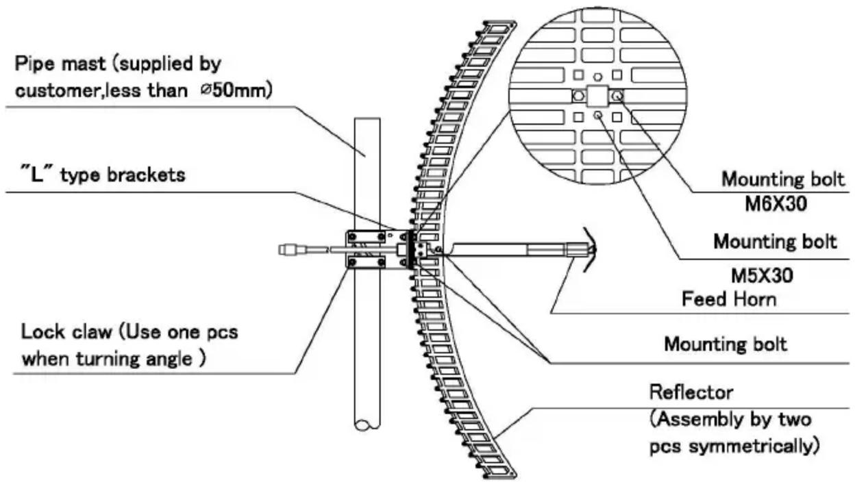
Installation:
- Assembly the two pieces of reflector symmetrically.
- Mount the feed horn on the reflector according to the Mounting diagram. Make sure the feed dipoles parallel with most bars of the grid reflector. When the feed dipoles and most grid bars are vertical to the ground, the antenna is vertical polarized. When the feed dipole and most grid bars are horizontal to the ground, the antenna is horizontal polarized.
- Mount the "L" type bracket at the back of the reflector, then mount the antenna on the mast supplied by customer according to the Mounting diagram.
- Test the antenna with equipment to make sure the antenna receive the best signal by turning the azimuth and pitching angle, then lock all the screws and seal the connector between antenna and cable.
| Electrical Specifications | |
| Frequency Range | 2.4GHz to 2.5GHz |
| Impedance | 50Ω |
| Gain | 24dBi |
| VSWR | ≤1.5 |
| Horizontal Beamwidth | 14° |
| Vertical Beamwidth | 10° |
| F/B Ratio | >30dB |
| Polarization | Vertical or Horizontal |
| Maximum Input Power | 100W |
| Connector | N Female |
| Application | Outdoor |
| Mount Style | Pole Mount / Wall Mount |
| Mechanical Specifications | |
| Antenna Dimension | 600×1000 mm |
| Weight | 3.5 +/-0.15 KG |
| Mounting Mast Diameter | ∅30~∅50 mm |
| Rated Wind Velocity | 216 Km/h |